1. Introduction
The development of energy and mechanical engineering in the extractive industries, through the diversification of drilling and oil production complexes, is the basis for the industrial and innovative development of the country, especially in those areas of oil deposits [
1,
2,
3,
4,
5,
6].
A large volume of earthworks in the construction of gas and oil pipelines and hydrocarbon production requires a wide range of reliable energy-efficient equipment and machines with working bodies of high resource durability. These indicators determine the volume of the market for drilling, milling earthmoving equipment, and rippers of increased productivity [
7,
8,
9,
10,
11,
12].
The analysis of the results of geological exploration confirmed that the main world reserves of hydrocarbon raw materials are accumulated in the territories of Siberia, the Far North, and the Arctic, territories dominated by complex terrain and the presence of frozen soils. Frozen soils have a sufficiently high strength at subzero temperatures and require special methods and equipment for their destruction. For the development of these oil fields, the development of infrastructure is possible only when solving the scientific and practical problem of designing the optimal forms of the working body of earthmoving equipment and mechanisms for the development of frozen, permafrost, and rocky soils [
8,
9,
10,
11,
12].
When destroying frozen soils with static rippers, it is necessary to ensure a minimum force of soil development, but sufficient for its destruction. At the same time, the resistance forces acting on the contact surface of the cutting edge and the frontal surface should not lead to the localization of fatigue stresses not only on the surface but also in the structural phase of the ripper tooth material [
13]. If this condition is met, the energy intensity of the soil destruction process will be minimized and the ripper loading will be full [
13]. A cross-section of the tip of the ripper tooth will be acceptable when the value of the ripping resistance of frozen soil reaches the minimum values while maintaining the contact cross-section area unchanged. This, in turn, will minimize the amount of wear on the operating device of the equipment and increase the energy efficiency of the soil excavation.
Therefore, the scientific challenge lies in the need for a mathematical description of the process of changing the design geometry of the ripper tooth in frozen soil and justification of criteria for optimizing the cross-section profile of the contact surface of the operating device tooth. There was put forward a scientific hypothesis that the study of the introduced restrictions on the condition of the distribution of resistance forces along the design geometry of the ripper tooth during the frozen soil excavation will allow creating an effective method for designing and optimizing the cross-section profile of a self-sharpening operating device of earthmoving equipment.
2. Research on the Effectiveness of Frozen Soil Excavation
Energy and total costs for the frozen soil excavation depend on the design features and service life of working bodies [
13,
14]. Goryachkin’s et al. research works are devoted to the improvement of the operating device efficiency. During the research, he posed two key questions [
5]: (1) what is the optimal shape of the working bodies for effective operation; (2) what should be the size and location of the components for control with minimal effort. We should also add a third question: what should be the service life and spatial shape of the operating device to ensure its high energy efficiency.
Experimental and theoretical studies of Zelenin in the area of cutting soil is allowed to justify the influence of depth of cut on cutting force, determining the stress distribution in the authoring environment, the influence of parameters of working bodies of earthmoving machines and blunting the force of the loosening of the soil.
To assess the effect of blunting of the working body on the efficiency of the ripper, Zelenin proposed an equation that takes into account its effect on the ripping force:
where
C is the number of strokes a drummer Road RI;
h is the depth of loosening;
s is the thickness of the cutting profile;
α is the cutting angle;
μ is the coefficient taking into account the degree of blocking; Δ is the coefficient of bluntness.
Reis established the nature of the load change. He proved that when loosening frozen soils, the load on the working body is variable and variable. The load change is on average 5–8 kN, and the frequency of change is 4–5 s−1.
Of the total volume of construction, preparatory, and repair work, more than 75% is performed by earthmoving machinery. When excavating frozen soils, the process of resistance to destruction causes a large amplitude of vibrations. Such force fluctuations increase the dynamism of the soil destruction process. The efficiency of earthworks is sharply reduced due to abrasive wear and bluntness of the working bodies during 2–4 shifts of operation. Today, working bodies used for soil excavation are of the shape designed 40–50 years ago. If in the 60s of the 20th century, the opening of the ground was carried out at a speed of 5 km/h, today these numbers reach 8–10 km/h. With the increase in the mass of mining and earthmoving equipment, the effect of dynamic forces on the cutting edge and the profile of the working bodies increased four times. The increase in the effective resistance forces is a consequence of the high traction and power properties of the unit when working with working bodies without structural changes. This indicates unsatisfactory durability of the working bodies of earthmoving machinery.
Foreign companies (Germany, Norway, Austria) offer a wide range of working bodies. Despite the advantages of imported working bodies, the unit cost of earthworks using this equipment exceeds the cost of soil excavation by domestic bodies by at least 1.5–2 times due to their high cost. Modernization of the working bodies for mining machines was undertaken by well-known “giants”: KOMATSU, JCB, Hitachi, and Volvo. The new model range of working bodies is based on European standards. The wide geography of operation of this type of equipment requires more stringent requirements for the cutting edges of the working bodies, considering the features of the rheological properties of the soil and its fracture mechanics in different regions of Russia and the CIS. The cost of imported working bodies of road and mining machines exceeds USD 4087 per unit, with a service life of up to 6105 cycles. In our regions, the service life is reduced by two times, and the aggressive environment and climatic conditions make it more difficult to repair the equipment at a remove from mechanized repair shops, which leads to an increase in the cost of work, labor intensity and unit costs [
14,
15,
16,
17,
18,
19,
20]. Research has established that the dynamics of the operating device, its trajectory and durability are affected not only by the rheology and mechanics of the soil but also by the design features and kinematics of the ripper [
4,
5].
M. N. Yerokhin et al. [
15] found that the cutting edge of the tooth chamfer angle, design geometry, and durability differ in different sources and depending on the methods of calculation. Their shapes, angle of penetration into the ground, and spatial projection are far from optimal values. Artemyev et al. proved the hypothesis that additional acting on worn teeth cutting forces form local zones of critical stresses and significantly reduce the reliability of the operating device. Amelchenko et al. proposed a methodological framework that determines the optimal effective technological properties of the working bodies of earthmoving machinery. Ananin et al. found that the angle of installation of the working body affects the specific energy intensity of the loosening process. The ability to change the loosening angle allows you to obtain the best results both during the deepening and during the steady-state loosening process. The possibility of increasing the loosening angle improves the conditions for the introduction of the tip and allows you to develop the soil in the immediate vicinity of the structures.
Despite the achievements of leading scientists in the modernization of working bodies, the development and design of an energy-efficient operating device with optimal features of a self-sharpening design profile of a low-resistance ripper for frozen soils remains a fundamental scientific challenge of mechanical engineering, which has not yet revealed the scientific and technological potential of energy-efficient technologies due to the lack of a scientific base and a satisfactory experimental solution [
16]. Therefore, the improvement of the mathematical model of the process of reducing the amplitude fluctuations in the resistance of frozen soils to destruction is a primary task of research that will allow establishing the optimal parameters of the cross-section profile of the operating device contact surface.
3. Study of the Effectiveness of the Ripper Tooth Inserting When Cutting Soil
During operation, overcoming the existing resistance forces, ∑Pi requires a large amount of energy to insert the ripper tooth into the ground. The force of friction of the back and profile parts of the embedded tooth Ptp and its sidewalls Ptw acquire max values. When developing overburden operations, the coefficient of soil resistance to cutting and chipping of the compacted mass depends on the physical and mechanical properties of the soil. When excavating clay soils and soils with high humidity, resistance increases due to the effect of soil stickiness. In the technological process of inserting and deepening the ripper tooth with increasing pressure, its profile area performs the function of a “press”. Due to this phenomenon, the contact surface displaces a certain proportion of moisture shifting the soil mass. The increasing force of the hydraulic pressure of the layer forms a clumped mass of soil in contact with the profile area of the ripper. The presence of such a plastic-phase structure in the soil increases its resistance before destruction. In the process of long-term exploitation, mining and drilling machines perform the most energy-intensive amount of work with the blunt cutting edges. As a rule, the size of the wear area of the tooth cutting edge reaches more than 18 mm.
When excavating frozen soils, the effective service life of the teeth varies from 237–715 h. The low service life of the operating device is caused by a cyclically unstable increase in the moments of cutting forces on the worn working surface of the blade. Therefore, an important scientific and practical task is to develop a technique for designing the spatial shape of the tooth that will ensure compliance with the balance of “useful” forces and resistance forces.
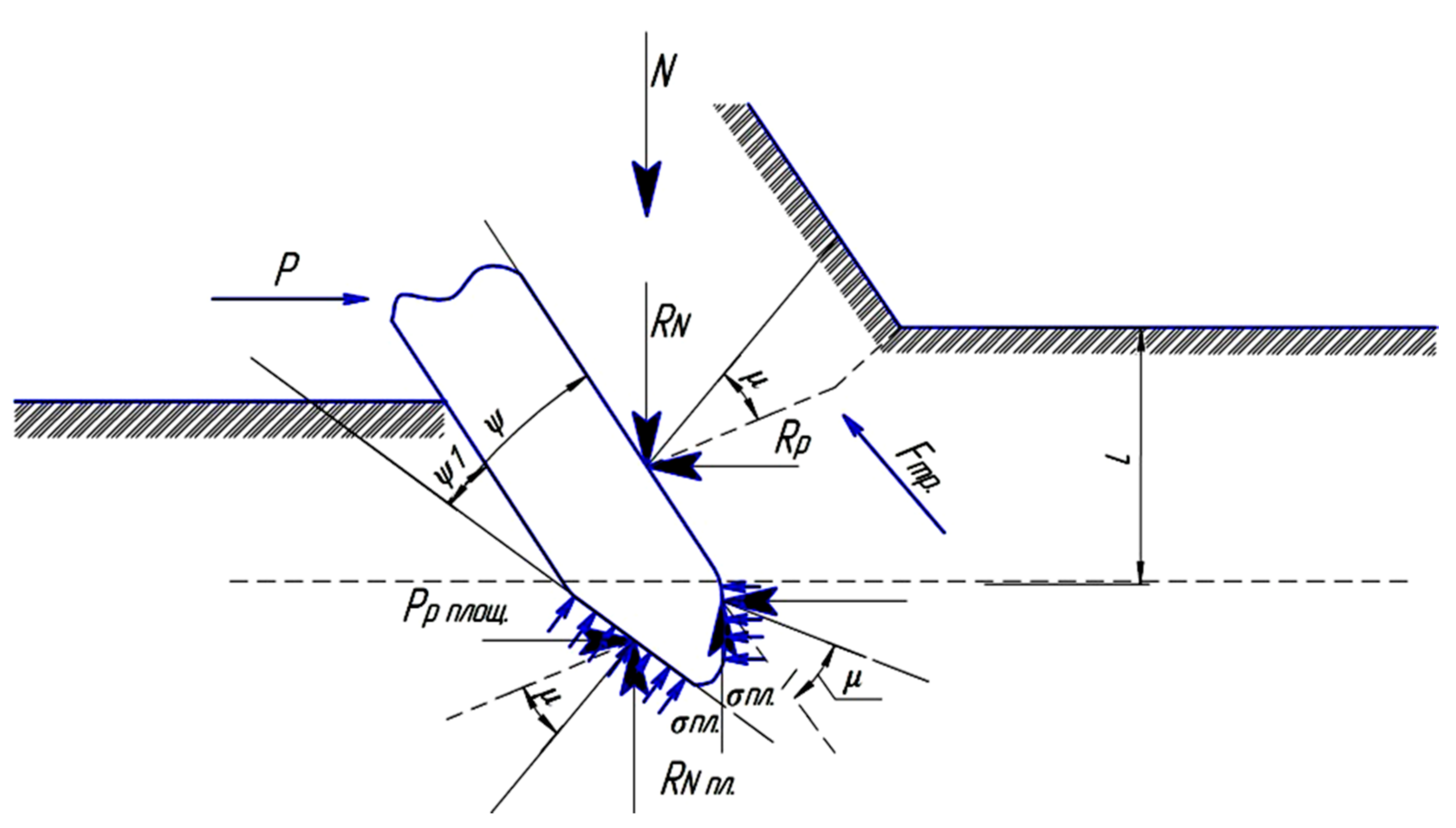
When moving a blunted operating device in the ground as it is buried, its contact area, in addition to the resistances of the spatial shape of the profile, shall overcome the forces of the resistance of the wear area [
14,
21,
22,
23,
24]. Thus, the hypothesis is proved that the contact area of wear is formed at a certain negative angle to the design trajectory of soil destruction (
Figure 1) [
16].
, —the angle of penetration of the tooth surface and the angle of deviation of the design surface; Ffr—ground friction forces; σa—the average pressure on the contact area of the tooth wall; RNa—the reaction of forces from the ground to the worn tooth surface; μ—the angle of friction of the worn cutting edge of the tooth; Ppf.—pressure on the wear area.
For a tooth with a worn edge, the normal and tangential moments of compressive forces when removing the soil form additional resistance forces. The change in the value of the friction force on the cutting edge of the tooth
, taking into account its wear, with a deviation from the axis of the design surface
(
Figure 1) can be set as a dependence:
where
ƒ is the coefficient of resistance to movement relative to the tooth surface.
The forces of ground resistance to cutting at the point of contact with the solid mass can be determined by the dependence:
where
σ1 is the coefficient of resistance to the shift of the soil layer relative to the trajectory;
Rs is the reaction of the soil forces on the ground when the layer shifts at a given point in the array.
Taking into account the force, the adhesion of particles between the soil layers
Fla significantly complements the mathematical model of wear and is determined by the dependence of the soil resistance:
where
A is the width of the inner wall of the tooth, m;
φ is the coefficient of adhesion of the soil layers; σ is the angle of the wear area.
It was established that the adhesion force of the layers Fla, the friction force Ffr, and the normal pressure forces are inextricably dependent on the geometric shape of the ripper tooth and the physical and mechanical properties of the soil.
The average pressure created on the contact area shall be as follows:
where
is the average pressure on the contact surface of the tooth wall N/m
2;
Sfb is the area of the back and front walls of the tooth, m
2;
RA is the reaction of forces on the contact area; σ is the angle of the wear area;
μ is the angle of friction of the worn cutting edge of the tooth.
Let us determine the value of the friction force
in the reaction of
RA forces acting on the contact area:
The work performed by the ripper tooth when it is inserted into the ground
Ains:
where
∑Fi is the sum of forces acting during the entire movement of the tooth up to the moment of its full insertion, kN.
The energy intensity of the operation can be expressed as:
where
φ is the coefficient of adhesion of the soil layers;
tЗг is the time required for the full insertion.
This means that with an increase in the transverse profile of the tooth and the area of the worn surface, the friction forces acting on it increase [
17,
25,
26,
27]. Accordingly, the energy intensity of the tooth insertion process and the destruction of the soil will increase with increasing friction forces of the worn part.
The design geometry of the cutting edge should minimize the soil resistance to cutting.
This scientific problem was also dealt with by Yu et al. In their work, they proved that the development of frozen soils for the most efficient machines used–mounted rippers–requires large traction forces. Localization of which is difficult due to the low coefficient of traction of the tractor with the surface of frozen ground. Lowering the required traction in the destruction of soil can be achieved due to the intensification of the working body which, in addition to the primary–progressive labor movement, providing a static burst pressure of the soil (the cutting), has additional traffic directly to the cutting edge or teeth, causing dynamic failure of soil [
28,
29,
30,
31].
Lemenkov et al. investigated the influence of cutting angles and the location of knives in the plan on the operation of knife, dump and bucket working bodies of earthmoving machines. Thus analyzed the resistance and intensity of soil cutting and digging, the volume of the prism lug in front of the blade and the bucket of the stroke speed and performance cars, etc., the quality of the working bodies, the stability of the digging process, and the durability of the machine. The optimal values of the angular parameters are determined, which are systematized in the table for each type of working body, and the possibility of their implementation is indicated, taking into account economy [
32,
33,
34,
35,
36,
37].
Studies have shown that the adhesion force of particles between the soil layers, as an additional resistance, is differentiated depending on both the design profile of the tooth and the angle of insertion of the cutting edge, as well as on the angle of sharpening. When the edge is blunted, areas of over-compaction of the soil are formed. They do not collapse but move during the destruction of the soil, creating additional resistance forces. When inserting a tooth with a sharpened edge at a certain angle, there is a decrease in the stress state of the soil due to the destruction of the over-compacted area of the soil, which contributes to the correct formation of soil chips and increases the ripping coefficient.
4. Mathematical Model
The mathematical model of the redistribution of resistance forces along the working edges of the tooth when designing the optimal surface profile of the operating device for ripping frozen soils was used.
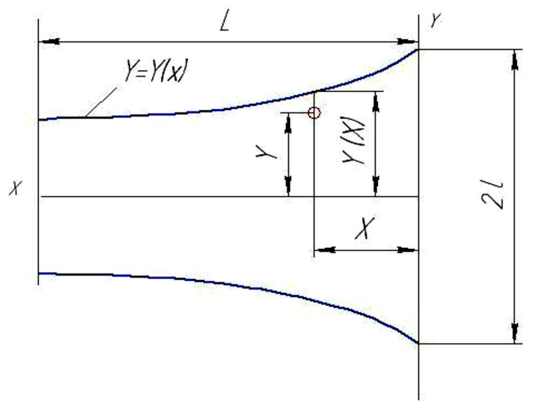
The value of the pressure along the limited surface of the variable width of the earthmoving machine operating device follows the equation [
10]:
where
p0 is the normal pressure at the mid-upper point of the operating device of the earthmoving equipment;
Q(
y),
P(
x) are functions of pressure changes along the width and length of the operating device, respectively:
where
L,
l is the length and, accordingly, ½ of the width of the operating device of the earthmoving machine;
X,
Y are absolute coordinates of the transverse profile of the surface selected at an arbitrary point;
x,
y are relative coordinates of the points of the transverse profile of the area of the earthmoving machine operating device (
Figure 2).
The component of the resistance force during the excavation of the soil mass by the working surfaces of the embedded tooth, normal to its surface, can be determined from the following:
Given the Equation (11), the law of change in the spatial shape of the transverse profile of the ripper tooth can be described by the following equation:
where
di is a constant coefficient;
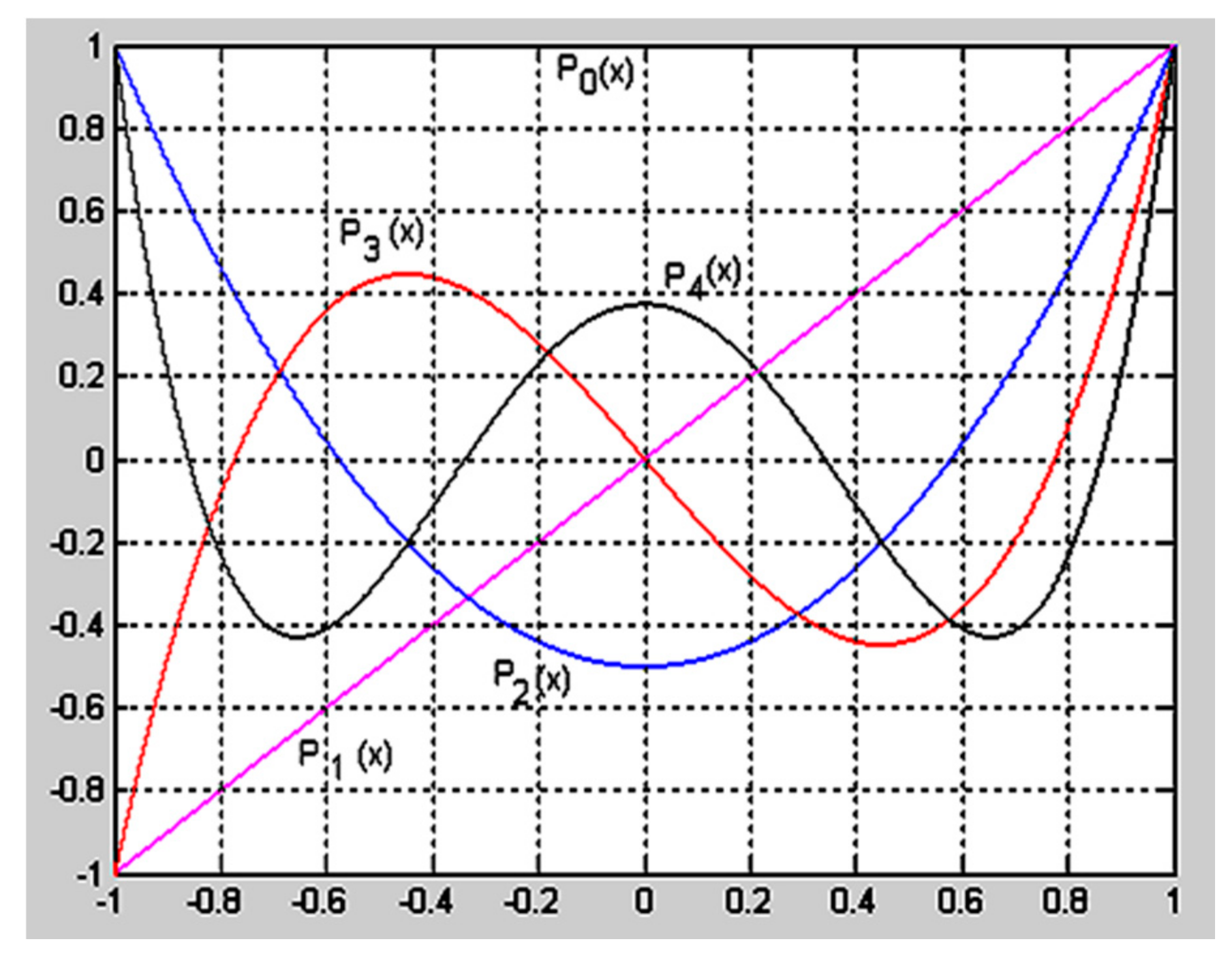
Pi(
x) are Legendre polynomials [
18] defined by the equation:
Special cases of Equation (13):
The graphical values of Equations (14)–(18) are shown in
Figure 3.
Taking into account the Equation (12), we can write the dependence for finding the contact area of the earthmoving machine ripper having a variable width as follows:
To justify the rational form of the investigated operating device of the earthmoving machine, it is important to take into account the following circumstances. The family of geometric shapes of the row (12) regulates the variability of the shape of the cross-section profile of the operating device, in identical cross-sections of the tooth area. Examining the effective area of the tooth, its optimal profile was determined by decomposition in a row. Following Equation (19), it was established that the area S of the operating device depends only on the first Legendre coefficient d0. During mathematical research, it was established that any variation in the profile of the operating device provides equal areas. The condition is feasible if the first term has the same coefficients for different coefficients of the Legendre polynomials. When finding the coefficients di(i ≠ 0), it is possible to determine such a cross-section of the surface at which the normal strength of resistance to soil destruction is minimal.
Substituting
i = 0 in Equation (19), we can find the value of the first Legendre coefficient:
For a known value of the cross-sectional area of the operating device of the earthmoving machine, the first term of the Legendre polynomials d0 is set from dependence (20).
Following Equations (11) and (12), we can determine the component of the resistance force of the soil excavation by the operating device
N applied to its surface:
where
ky is the coefficient of uneven pressure distribution over the area of the operating device of the earthmoving machine:
This means that the functions defined by Equations (10) and (14) are included in a definite integral. The principle of distribution of the normal component of the force
N of resistance during earthworks depending on the changing area of the cross-section of the operating device can be presented by dependence (22). Its equation is written under the symbol of the sum, that is:
Analyzing the components of Equation (23), it can be seen that the transverse profile of the operating device will have optimal parameters with the minimum values of the series.
If we restrict Equation (24) to the first five terms of the series, we obtain:
For further research, let’s accept some conditions and assumptions.
The value of Equation (13) must not be negative in the range of changes in the variable
x (1 ≤
x ≤ 1):
It is not allowed to change the width of the cutting edge of the tooth of the operating device less than the established one, i.e.,
Analyzing the curves of the graph (
Figure 3), it is found that the
min values of the Legendre polynomial are available only in the following cases:
P1(
x) for
x = −1;
P2(
x) for
x = 0;
P3(
x) for
x = −1 and
x = 0.44721;
P4(
x) for
x = 0.65465 and
x = −0.65465.
To fulfill the condition of Equation (26), some inequations must be taken into account:
Taking into account the above, the determination of the optimal and effective cross-section of the operating device with a high service life of the earthmoving machine consists in solving the problem of the target function (25), taking into account the conditions of Equations (26)–(32).
5. Results and Discussions
In this respect, the MatLab software (MathWorks, Natick, MA, USA) was used to perform a large array of calculations of input and output parameters, the main results of which are shown below.
5.1. Restriction I. Nonnegativity of the Width of the Cross-Section of the Earthmoving Machine Operating Device
Subject to the condition for the nonnegativity, the gradient that characterizes the choice of the operating device profile (26) shall correspond to:
For practical purposes, the calculation result is interpreted as invalid, but mathematically correct. The minimum value of the objective function (29) was obtained taking into account the accepted restriction.
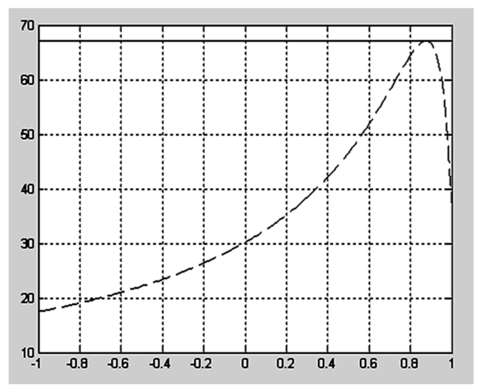
5.2. Restrictions II. The Width of the Cutting Edge Shall Be Limited by the Values of the Profile, the Width of Which Cannot Have Negative Values
The result of the task solution taking into account Equations (30) and (27) prescribing the minimum value of half-width of the cutting edge of the transverse profile of the earthmoving machine operating device is shown in the graph curve (
Figure 4).
It is obvious that the solution according to Restriction II is unacceptable since, in this case, the specified operating device will not be sufficiently firm.
5.3. Restriction III. The Overall Width of the Operating Device Profile along the Entire Length Shall Be Assumed to Be at Least the Values Specified in the Technical Specification
Applying inequalities (26) to the range of variation
x (−1;1) under study, the following condition is formed:
in the solution, the segment under study will look like:
When calculating by the condition y(x) ≥ l, the width of the operating device along the entire length remains constant.
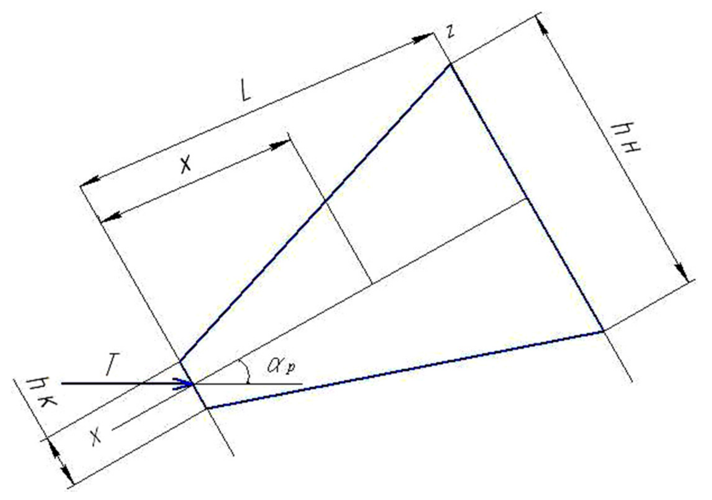
5.4. Restriction IV. Condition of Equal Strength of the Operating Device of the Earthmoving Machine
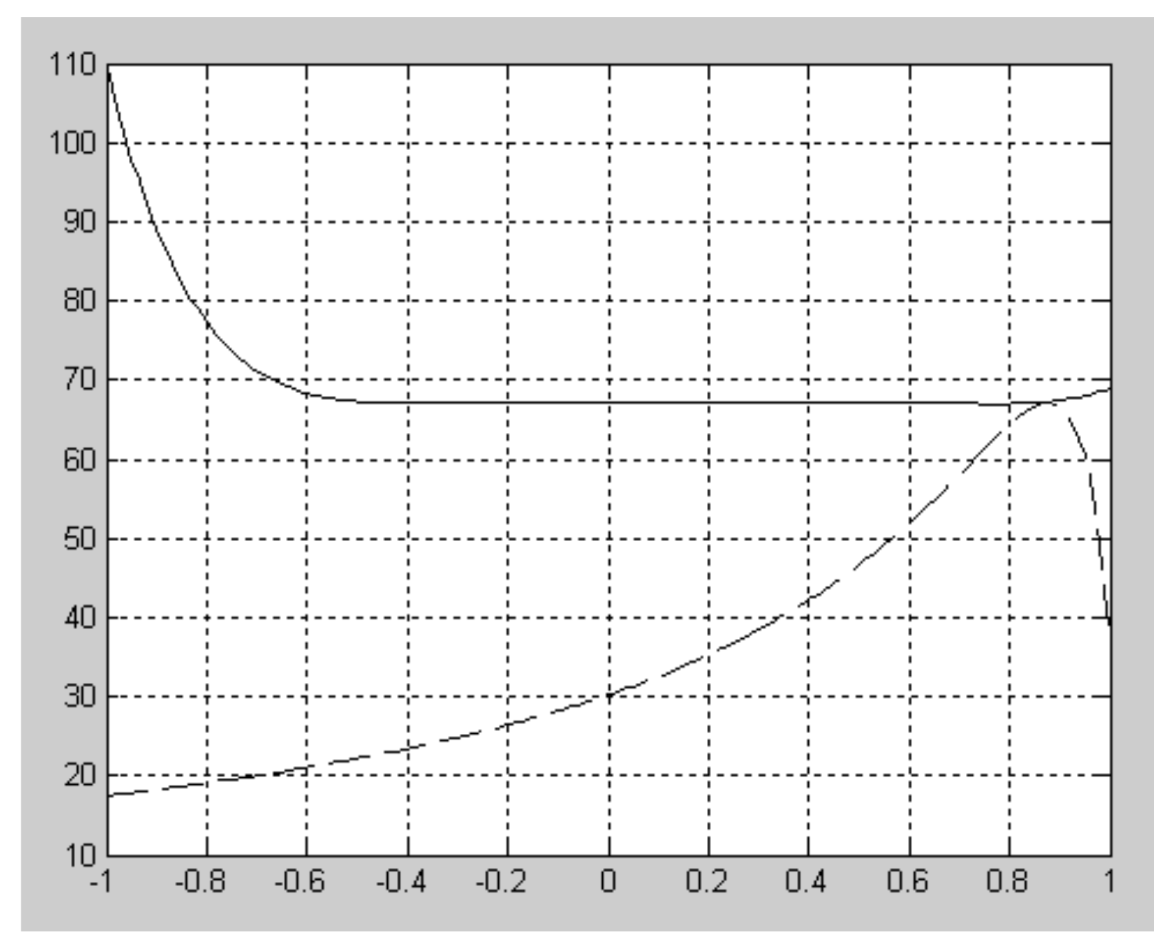
The design diagram for taking into account the restriction on the equal strength of the operating device is shown in
Figure 5.
The physical meaning of the restriction on the strength of the operating device of an earthmoving machine can be defined by the equation:
where [
σ] is the permissible bending stress of the operating device material;
T is the pulling force of the static ripper; p
αp is the cutting angle of the frozen soil; and
h is the width of the side face of the operating device.
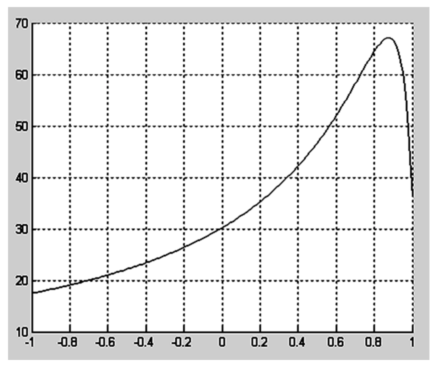
The result of the calculation according to Restriction
IV is shown in
Figure 6.
However, with a view for the cutting edge to withstand the increased loads that occur when the operating device collides with an insurmountable obstacle, it is necessary to configure the operating device basing on optimizing its profile according to condition (36), taking into account the width of the side face of the operating device
h:
where
hk,
hH are the height of the operating device below and above, respectively (
Figure 5).
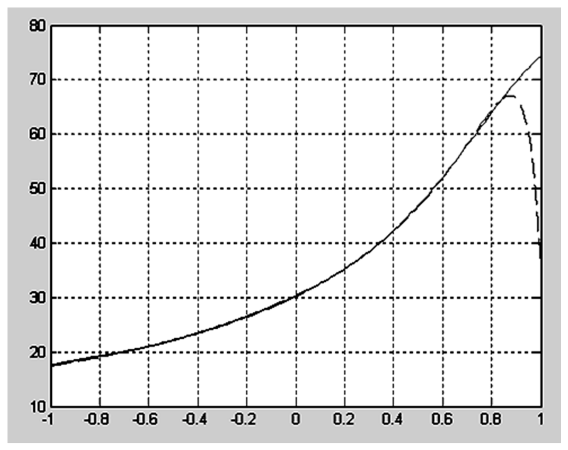
The obtained dependence shown in Equation (36) was described by a nonlinear dependence, taking into account the width of the side face of the operating device
h. Graphically, the dependence shown in Equation (36) is formed as a complex curve of the graph (
Figure 7). The initial data are as follows:
T = 250 kN,
hk = 15 mm,
hn = 180 mm,
L = 250 mm,
= 30
0, [σ] = 200 MPa.
Analyzing the graphs of
Figure 7, it was found that the design geometry of the studied profiles of the operating device of equal strength (
Figure 6) coincides with the values of the optimal profile (
Figure 7). The only exception were the values of the cutting edge.
The value of the specific pressure
ki is the ratio of the resulting normal force
Ni acting on the surface of the operating device to its area
Si:
The specific pressure k1 distributed over the profile of the ripper tooth under condition (36) is 46.2.
5.5. Restrictions V. The Condition of the Ripper Tooth Profiles of Equal Strength and Limitations of a Cutting Edge Width
By limiting the design geometry of the cutting edge to the spatial dimensions of its width and condition (4), it is possible to design an operating device that creates max pressure on the excavated soil layer. Thus, the process of frozen soil destruction is more efficient and less energy-consuming with the standard technological parameters of the operating device and the accepted operating modes of the machine. Therefore, the problem of substantiating the optimal parameters of the operating device’s spatial shape and the design geometry of its cutting edge was solved. Its application shall significantly reduce the energy consumption of the power unit of the equipment.
Thus, if we fulfill the condition that the final values of the cutting edge width shall be limited and integrate the Equation (36), we can obtain the following:
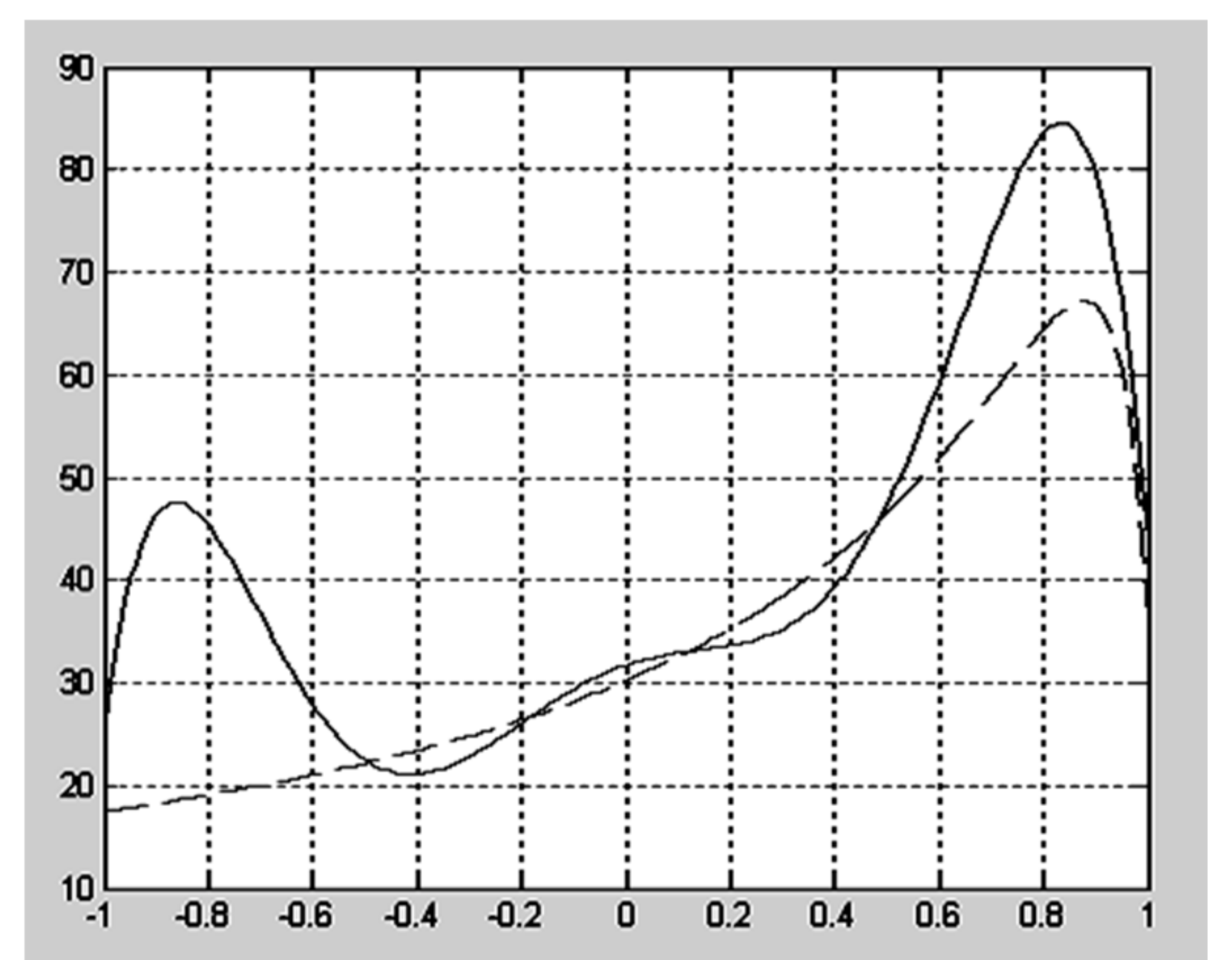
Following the analysis of graphs (
Figure 8), with accepted Restriction V, the change in specific pressure was established depending on the spatial shape of the tooth, geometry and sharpening angle. Thus, the optimal effective values of the profile will be those at which the calculated specific pressure on its surface will be less. Under the established restrictions, the optimal parameters of the tooth profile are characterized by a curve describing the effect of specific pressure no higher than 43.2 MPa.
5.6. Restriction VI. Condition of Equal Strength and Limited Width of the Profile above the Cutting Edge
Figure 9 shows that following Restriction
VI-, the specific pressure is
k3 = 41.4 with the relative area of the operating device
S3 = 138 cm
2. The specific pressure applied to the operating device decreases if the area increases.
When increasing the operating device area to
S4 = 140 cm
2, the specific pressure will be
k4 = 40.07, which is less than
k3 (
Figure 10).
Studying the spatial shape of the profile obtained for the values
S4 = 140 cm
2 and
k4 = 40.07 (
Figure 10), an inevitable increase in its geometric dimensions was observed. Estimating the sevenfold change in size from the cutting edge to the upper part of the operating device, the values of its half-width tend to approach 11 cm.
With an increase in the cross-section width of the profile, there is a more uniform distribution of specific pressure over its area. Due to a slight change in the specific pressure, within 3%, an increase in its metal content and geometric dimensions will be unjustified.
6. Conclusions
After conducting research using a wide range of mathematical modeling tools, the following conclusions were made:
The resistance forces acting at the point of application of the soil mass to the operating device increase with large contact areas of the ripper and its worn cutting edge. The larger the contact surface area, the greater the resistance force. However, the forces of resistance to cutting the soil are great only in the initial period of soil excavation, at the time of insertion and deepening of the tooth. Further, the “torn off” layer of soil, moving along the trajectory of the tooth profile and reaching its half-width, reduces its specific pressure. This means that varying the area and design geometry of the cutting edge will affect the formation of optimal parameters of the operating device. Thus, both the hydraulic drive and the power unit of the equipment will spend more power Nhd to perform the same amount of work and overcome the resistance forces. As the forces of resistance to soil cutting increase, the energy intensity of the inserting will also increase. The optimal values of the energy intensity of the process shall be limited by the values of the spatial shape, dimensions and geometry of the ripper tooth. The conditions that characterize the optimal values of the profile and shape of the operating device are described by six restrictions.
The forces of resistance to cutting frozen soil are variable in size and time. Their distribution depends mainly on the depth angle, the design trajectory of the operating device and the design features of the contact surface profile. It is also established that the stresses that occur in the compacted layers of frozen soil during chip shifting have maximum values, therefore, this operation is the most energy-intensive.
The proposed mathematical methods using Legendre polynomials demonstrated adequate equations in the proposed conditions and the validity of restrictions to justify the energy-efficient parameters of the ripper tooth of earthmoving equipment.
It is important to ensure the condition of strength for the limited width of the operating device profile when it interacts with an insurmountable obstacle. When designing an effective profile of the operating devices, the solution of this probabilistic problem was based on compliance with the conditions justified taking into account restrictions IV and V.
Since operating devices with blunted cutting edges of the tooth experience increased loads when working on frozen soils, it is necessary to strive to reduce the specific pressures on the working surfaces. This condition and the condition of strength correspond to the profile of the operating device obtained due to restriction VI.


 ,
, 


