1. Introduction
Reducing vehicle weight can effectively improve the mileage of new energy vehicles. A direct and efficient way to reach the target of lightweight design is the substitution of low-density but high-strength materials like aluminum, magnesium, fiber-reinforced composite materials for steel [
1,
2,
3]. One innovative concept of lightweight designs is so-called smart structures, in the manufacturing of which is often required to join tubes with different materials. However, the joining of parts in different materials is a challenging task. Some conventional joining techniques are not suitable for making high-quality joints [
4,
5,
6]. As a result, many researchers have focused on searching for new methods.
Joining processes based on plastic deformation of at least one joining part promised great potential regarding the production of multi-material joints [
7]. The use of plastic deformation for joining parts potentially offered improved accuracy, reliability, and environmental safety as well as creating opportunities to design new products through joining dissimilar materials [
8]. Joining plastic deformation for tubes mainly has the following several ways. For instance, in the friction stir welding (FSW) process, materials around the interface are heated by friction between continuously moving surfaces, and then the force is applied to cause large plastic deformation for bonding the surfaces. According to Chen et al. [
9], small-dimension Al 3003 pipe and pure copper pipe of the thin wall (Al: 1.5 mm; Cu: 1 mm) and small diameter (19 mm) were successfully joined by a developed welding method with a specially-designed friction stir welding (FSW) system. Moreover, joining by mechanical crimping was developed in 1930 to join couplings onto hydraulic hoses, which used segmented tools and was still the major application of this process [
10]. Shirgaokar et al. [
11] used mechanical crimping to join tubular parts without an intermediate plastic or rubber tube. The influence of workpiece positioning, press jaw movement, and tool geometry on the pull-out force and the material thinning in the joint zone were examined. In contrast to mechanical crimping, joining by hydraulic crimping uses an elastomer to apply the required forming pressure on the surface of the workpiece to make a joint [
12].
An alternative technique for joining dissimilar materials by plastic deformation is driven by electromagnetic force, which uses pulsed magnetic fields to form highly conductive metals at a high speed. Magnetic pulse welding (MPW), as it is known, is one of these cases. The typical setup of MPW consists of the EMF machine, tool coil, and workpiece. This setup can be represented by an RLC circuit in which the forming machine is symbolized by the inner resistance
Ri, the inner inductance
Li and the capacitance
C. The combination of tool, coil, and workpiece is considered to be the consumer load of the circuit. Compared to other welding technologies, the process of MPW is environmentally friendly for no emission of heat, radiation, gas, or smoke during the process, which provides safer and cleaner conditions for the operator. It allows the joining of dissimilar material combinations, keeping their mechanical and chemical properties intact quickly and cost-effectively [
13]. Time-consuming post-weld activities like cleaning and finishing are not required.
Electromagnetic crimping is another process variant, whose principle is similar to MPW. For the manufacturing of crimping connections, the material of one joining part is formed into an undercut of the other partner. Thereby, an interlock, which ensures the load transfer between both parts is generated [
14,
15,
16]. Based on its characteristics, many researchers have studied electromagnetic crimping technology. For example, Golovashchenko [
17] examined the influence of circumferential grooves geometries on the achievable push-out strength. The results showed that when the tube wall just touched the bottom of the groove, the push-out force was increased with a decreasing groove width and an increasing groove depth. Park et al. [
18] analyzed the influence of geometric parameters on joint strength through simulations and experiments. Different from the study of Golovashchenko [
17], they used the same charging energy in all of their experiments and observed an increase in the transferable load with an increasing width and depth. Based on these results, axial and torque joint were designed and guidelines for designing crimped joints were established. In addition, Weddeling et al. [
19] studied the influence of groove shapes (rectangular, circular, and triangular) on the pull-out force. It was found that higher deformation/higher stiffness in the tube was existed due to the mandrel groove geometry, smaller resulting angle, and partial shearing at the groove edge. To facilitate the connection design, Weddeling et al. [
20] further presented an analytical approach for the prediction of the joining zone parameters with respect to the loads to be transferred. The experimental studies in which groove dimensions and their shape were major parameters regarding the load transfer under quasi-static tension are performed to validate the approach. Then they developed design strategies and a process window for the manufacturing of such crimped joints. The studies of electromagnetic crimping mentioned above mainly used the typical setup of tube compression processes, and most of current investigations and publications dealing with crimped joints focused on the groove dimensions. However, the present electromagnetic crimping method for pipe fittings is to use a circular magnetic collector. A magnetic collector of one diameter can only connect pipe fittings of the corresponding diameter. This kind of electromagnetic crimping requires the replacement of magnetic collectors when joining the tubes with different diameters, and the cost is high. Therefore, a novel method is proposed to connect pipe fittings of different diameters without changing the coil.
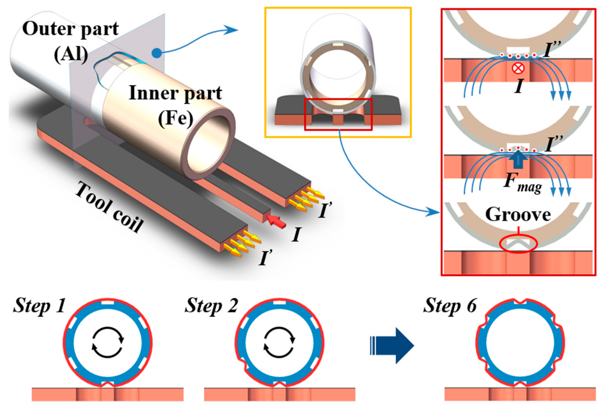
In this paper, a new approach for electromagnetic tube-parts connections was proposed. A flat coil was used for the manufacturing of torque joints. In this way, it becomes more convenient and flexible for the industrial application of electromagnetic crimping, and only one tool coil is enough to be used for tubes with various diameters. Moreover, in the case where a single connection of large energy cannot be achieved due to the discharge energy limitation of the device, a multi-step connection under small energy can be realized based on the new approach.
3. Results and Discussion
3.1. Torsional Strength and Failure Modes
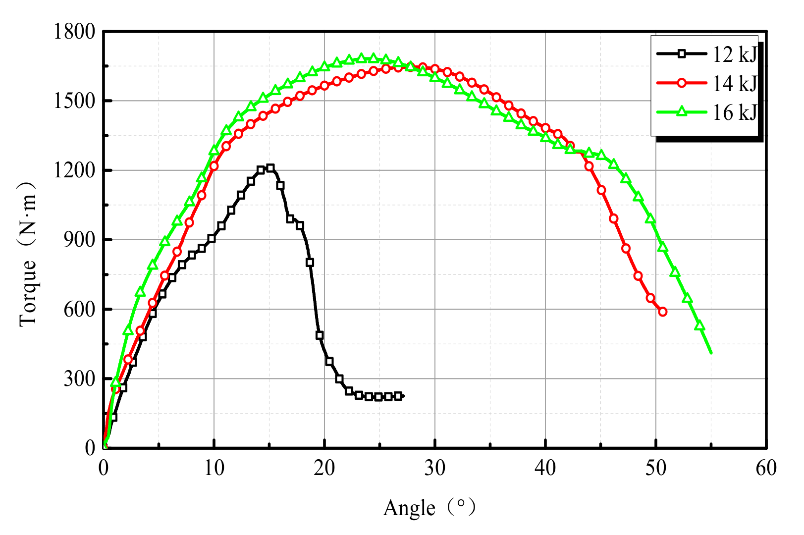
Figure 5 shows three typical torque-angle curves of the pipe electromagnetic crimped joints under different discharge energies. It could be found that the torsional strength of the joint under 12 kJ was obviously lower than that of joints under another two energies. While the trend of the joint with 14 and 16 kJ was similar. At first, the torque increased approximately linearly with the increase in the angle of rotation. When the torsion angle was about 15°, the torsion force of the joint with 12 kJ reached its peak (about 1200 N.m). Subsequently, its value decreased rapidly with the increase of the torsion angle. As for the joint with discharge energies of 14 and 16 kJ, the torsion angles reaching the peak (about 1650 N.m) were delayed at about 26°, and then they fell more slowly than the joint with 12 kJ.
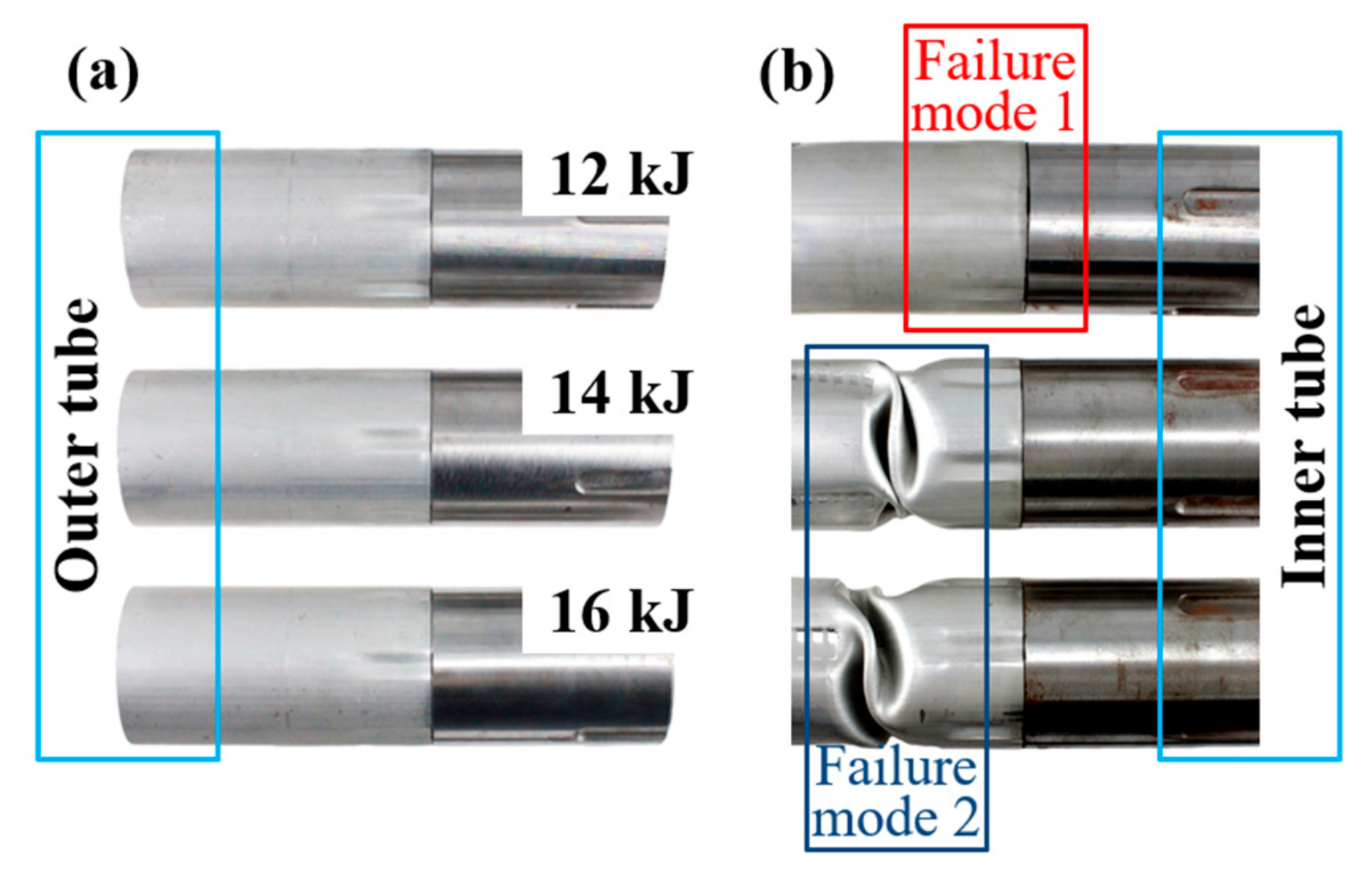
Figure 6 shows the specimens before and after the torsion test. It could be seen that the outer tube was mainly deformed, and two failure modes were observed during the torsion test. At the discharge energy of 12 kJ, the outer tube twisted out of the groove (called failure mode 1). This was because the discharge energy was small, and the forming force was insufficient. There was not enough interlock between the outer tube and groove to withstand the torque. At the discharge energy of 14and 16 kJ, severe distortion occurred at the outer tube (failure mode 2). This indicated a relatively higher degree of interlock between the outer tube and groove.
Figure 7 shows the torsional process of the two failure modes during the torque test. Based on the final failure position, three typical torsional angles were selected. It basically represented two stages: one was that the torque increases from zero to maximum, another was torque decreasing. Wherein φ was the angle the outer tube rotated relative to the inner tube in the connected zone. At the first stage, it could be seen that the outer tube rotated at a small angle during the torque test for both failure modes, and the φ
1 value of failure mode 1 was a little bigger than that of failure mode 2. This indicated that the outer tube was mainly distorted and the dislocation in the groove was small. At the second stage, the φ
2 value of failure mode 1 was much bigger than that of failure mode 2. This illustrated that the two tubes for failure mode 1 had a larger dislocation at the stage.
In a word, during the torsion test process, when the torque was small, the outer tube was elastically deformed. At this stage, the torque was approximately linearly increased with respect to the rotation angle. When the strength of the interlock was lower than the strength of the outer tube parent material, the interlock would be deformed with the increased torque, to be twisted out from the groove (failure mode 1). While the strength of the interlock was higher than the strength of the outer tube parent material, distortion occurred on the outer tube parent material (failure mode 2).
3.2. Fittability of Joining Zone
To obtain a high-quality crimped joint, it is important to ensure the consistency of the deformation of the outer tube on both sides of the groove.
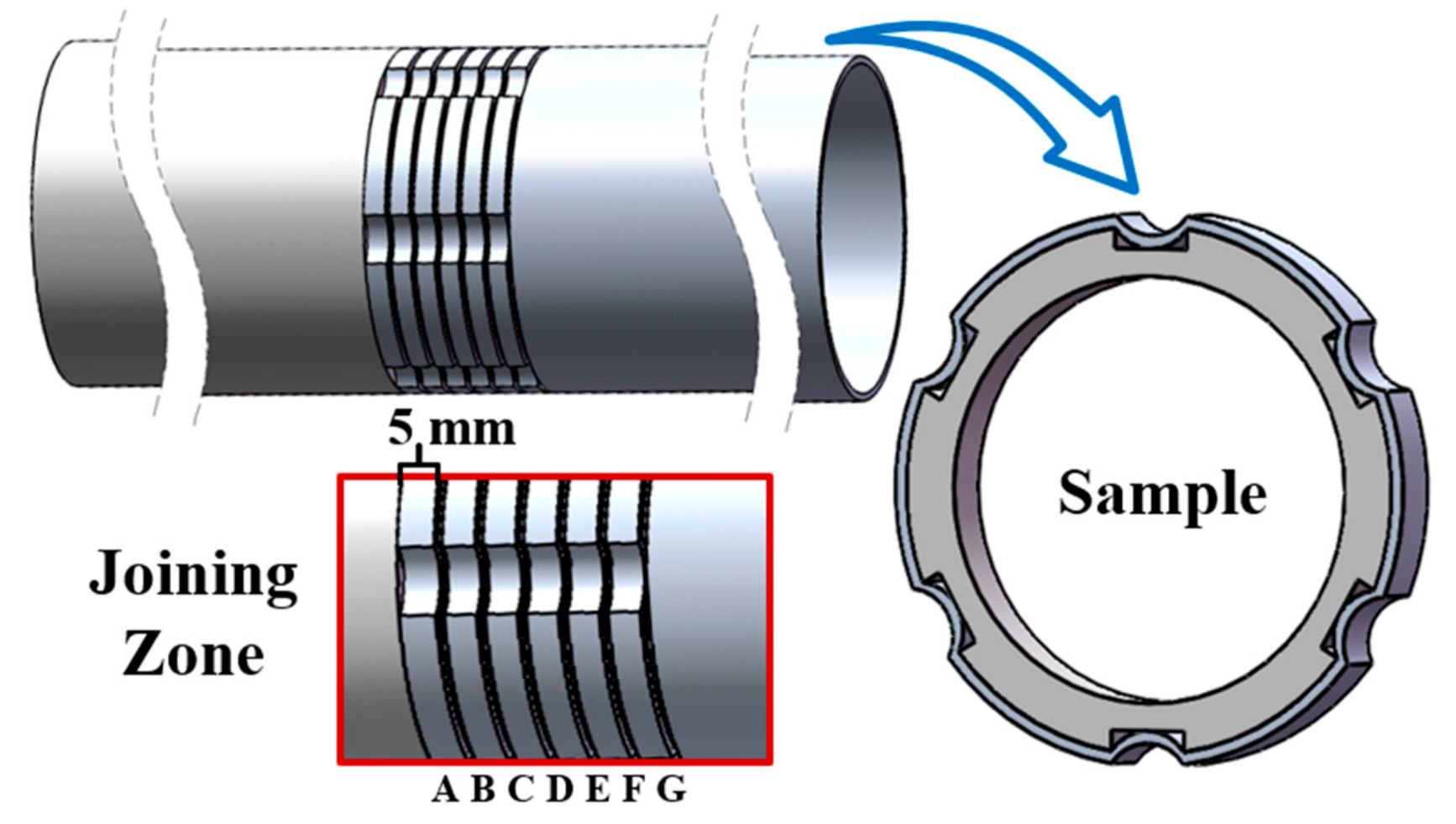
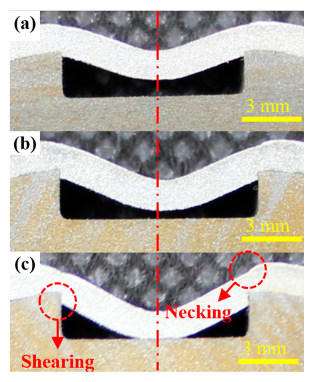
Figure 8 shows the cross-section observation of the joints at position D (see
Figure 4). It could be clearly seen that the outer tube wall filled the groove of the inner tube under the action of the electromagnetic force, and a gap between the inner wall of the outer tube and groove base could be observed as well. The deformation of the outer tube was symmetrical with respect to the centerline of the groove under different discharge energy, and the maximum deformation of the outer tube increased with the increasing discharge energy. The outer tube wall made contact with the groove base when the discharging energy was 16 kJ. The shearing and necking near the edge of the groove could be seen clearly as well.
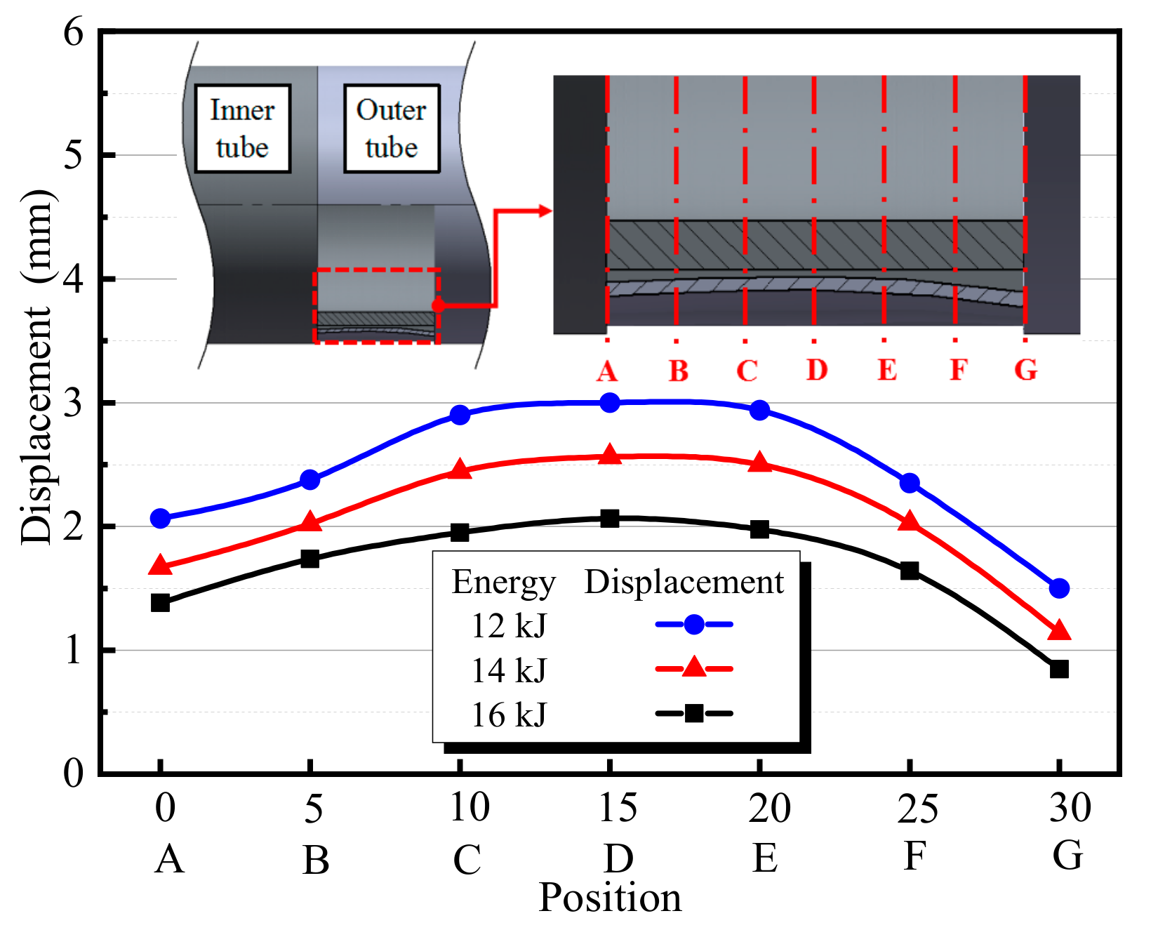
The above test results showed that the strength of the joints with 14 and 16 kJ was higher than that of 12 kJ. It could be attributed to that the increase in discharging energy resulting in increasing deformation of the outer tube to fill the groove. Greater resistance could be provided during the torsion process. In addition, the deformation of the outer tube was different in the groove, so the specific deformation value was measured as shown in
Figure 9. It could be found that the maximum deformation of different positions in the axial direction of the joint formed under various discharge energies was different. The deformation of the outer tube in the middle position of the connecting area (position D) was the biggest and gradually decreased from the middle to the two sides. The overall deformation near the inner tube side (region from position A to position D) was bigger than that away from the inner tube side (region from position D to position G) in the connected area. This was mainly due to the difference in the maximum deformation between position A and position G. There were two main reasons for this difference: one was the difference of the constraint imposed on between position A and G. It could be seen that position A was a free end while position G was not, which made it easier for position A to deform. Another was that position G was located on the edge of the coil, and the cross-positional area of the coil at the location of position G differed from that at the location of position A. The electromagnetic forces experienced by the outer tube wall at position G was lower than that at position A. As for the reason why position G was located on the edge of the coil, it was because without a mandrel supporting inside the outer tube. If the position of the connection region was moved toward the side away from the coil edge, the region closed to the connected area on the outer tube would be deformed by electromagnetic force, which would affect the joint quality.
However, the strength of the joint did not increase as the energy increased continuously, because of the existing thinned area (the partial shearing of the tube at the groove edge) as proved by Weddeling et al. [
19]. The thinning of the tube due to shearing at the groove edge would weaken the joint more than the strength increase seen by forming the tube into a groove, to cause overall joint strength to decrease. As for the shearing of the tube, they also pointed out that the effects of shearing played a prominent role in the strength of the joint. In this study, a geometric analysis model was established to investigate the degree of shearing and necking of the outer tube under different discharge energy, as shown in
Figure 10.
The shearing rate is defined as
The necking rate is defined as
where
So is the original thickness of the outer tube,
Sd is the minimum wall thickness of the necked area in the direction of the sidewall of the groove, and
Sτ is the shearing displacement in the direction of the sidewall of the groove. The values of
So,
Sd, and
Sτ were measured under the microscope, which were averaged from the value of three repeated samples under one discharge energy.
Figure 11 illustrates the shearing and necking rate distribution of the outer tube wall at different cross-positions under three discharge energies. It could be seen from
Figure 11a that the shearing rate of the outer tube wall in each position increased with the increase of discharge energy. The shearing rates at the middle of the connected area (from position C to position E) changed more obviously with the increase of discharge energy. Moreover, before the tube wall made contact with the groove base, where the outer tube wall was deformed large, the shearing rate at the groove edge was large. However, after the tube wall reached the groove base, the degree of the shearing rate changed less. The shearing rates of the different positions of the joint formed under the same discharge energy were greater as the energy increased. This indicated that the position had a greater influence on the shear rate. A similar trend occurred in the necking rate of the outer tube, as shown in
Figure 11b.
Furthermore, the shearing and necking rates of the two typical sections under different discharge energies were compared as shown in
Figure 12. It could be found that the shearing rate was a little bigger than the necking rate on the same position, and the difference increased as the discharge energy increased. Besides, the shearing and necking rate of section A was far less than that of section D. This indicated that the shear and necking rate was lower in the position with small deformation.
3.3. Microstructure Observation
The mechanical properties of metal materials after deformation significantly depend on microstructural characteristics. To study the performances of the joint in-depth, microstructure observation of the outer tube filling in the groove was carried out.
Figure 13 shows the metallographic structure of the outer tube in detail, which was scrabbled by many metallographs. Maximum deformation location (position D) was used for analysis. It could be seen that serious deformation of grains occurred in the region near the edge of the groove by comparing with grains in other regions. In particular, some of the grain was obviously elongated. This could harden materials in this area, thus increasing the strength of the joint. The grain was deformed in the direction of the arrow in the figure. It was elongated most severely at the edge of the groove, and the degree of elongation decreased with the direction of the arrow. Moreover, a v-shaped thinned area could be seen in the outer wall of the outer tube.
Under the action of the electromagnetic force, the strain rate during deformation would reach about 10−3 s−1. The material would flow rapidly to a certain extent at such a high strain rate. When the outer tube was filling into the groove, the materials were sheared along the sidewall of the groove, and severe plastic deformation of the outer tube occurred. At the same time, materials in other areas might flow to the necking area from the nearing region. So the shearing rate was not equal to the necking rate as the results are shown above.
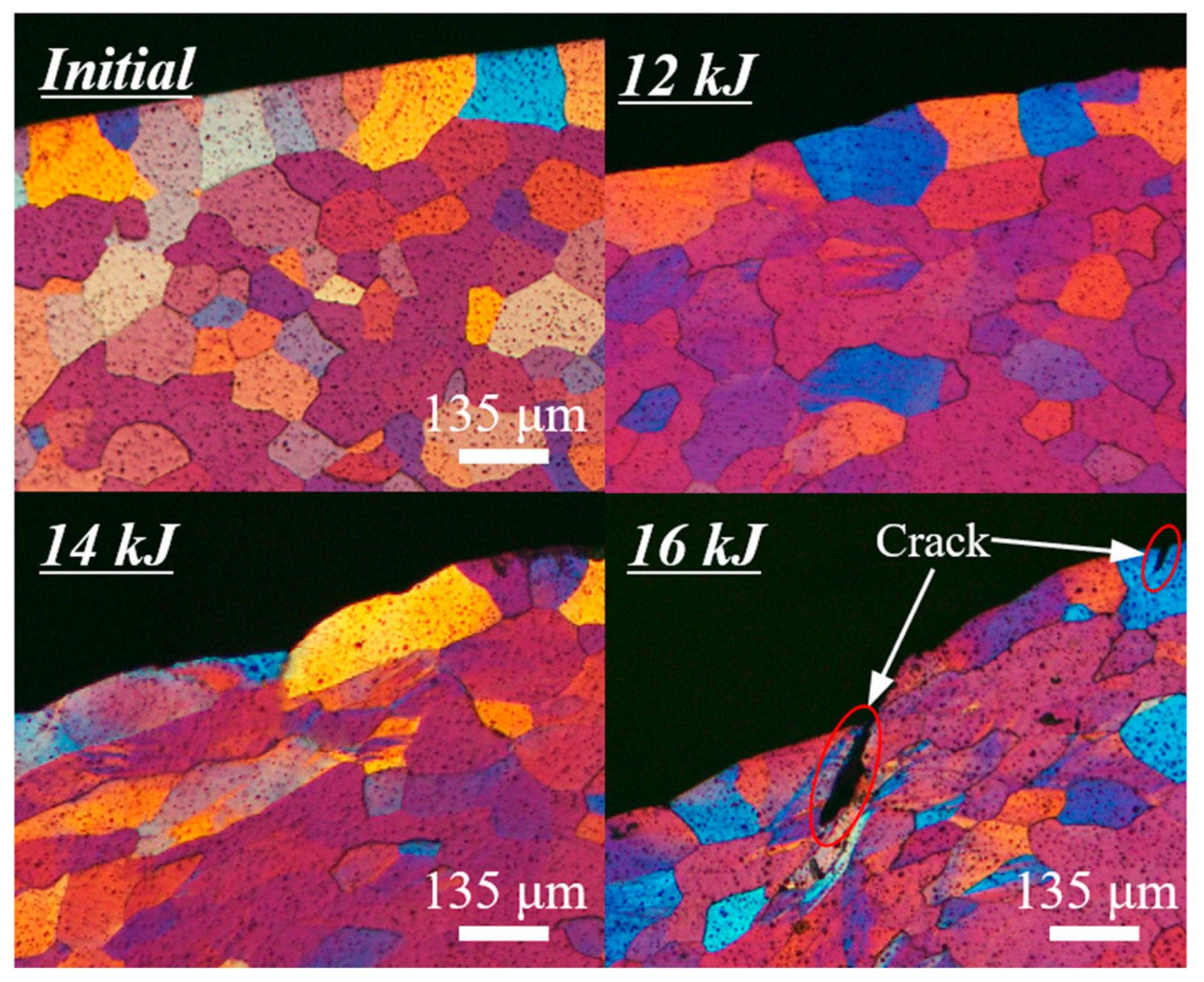
Figure 14 shows local enlargements of thinned area (necking area) in position D under different discharge energies. It could be found that the degree of necking of the outer tube wall became more obvious with the increase of the discharge energy, and v-shaped thinned area could be obviously seen at the discharge energies of 14 and 16 kJ. Especially, some cracks were found in the necking area at the discharge energy of 16 kJ. In addition, grains in the necking area of the joint formed under 12 kJ were almost not elongated compared to the grain of the original outer tube. However, elongated grains could be seen in the necking area of the joints formed under 14 kJ and 16 kJ because of the greater electromagnetic impact force.
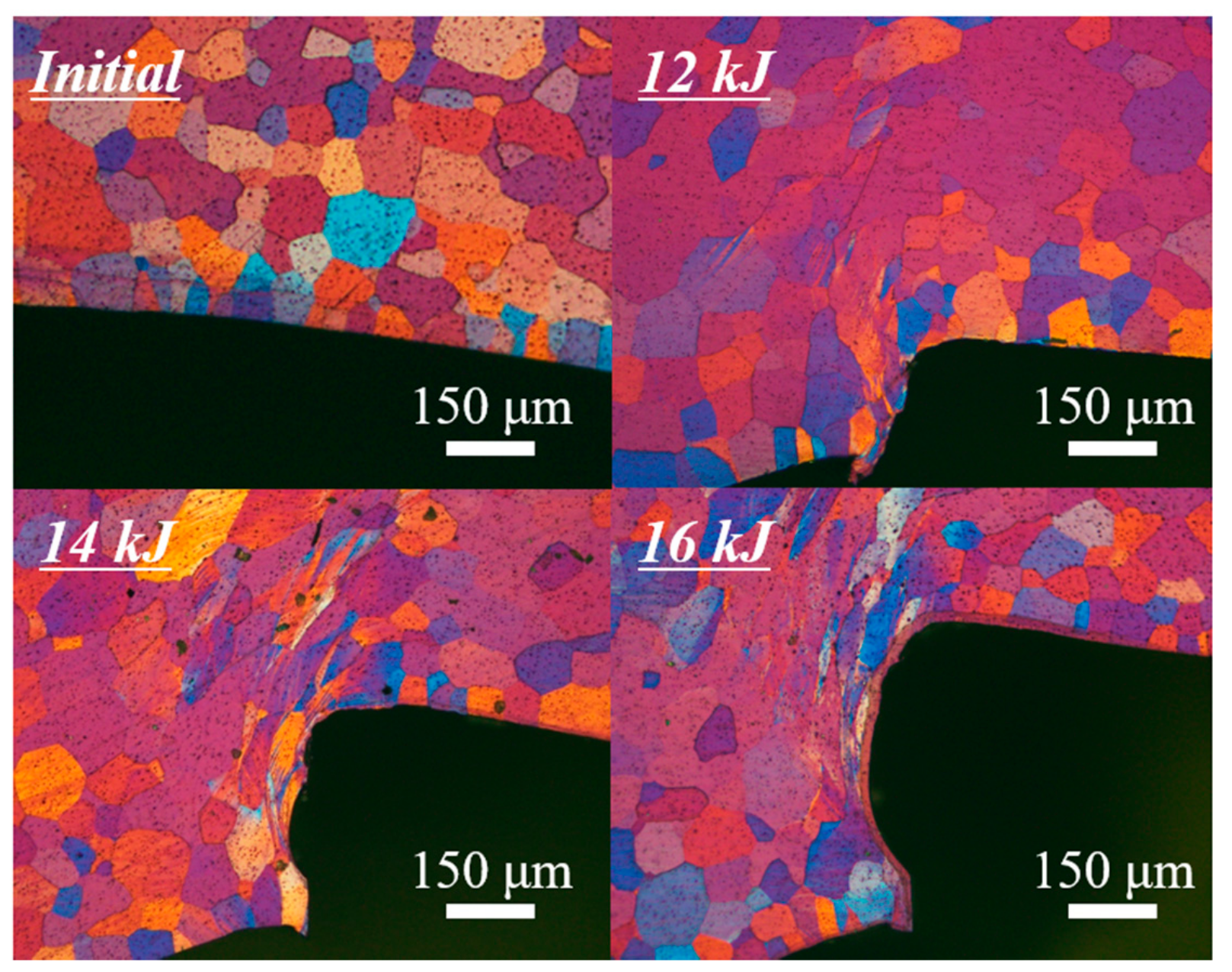
Figure 15 shows local enlargements of the shearing area of position D under different discharge energies. It could be obviously observed that the deformation degree of the shear area increased with the increase of discharge energy. The grains in the shearing area of the joint formed under 12 kJ were not obviously elongated, while the grains of the joint formed under 14 and 16 kJ were severely stretched.
In general, under torsional loading, the deformation at the edge of the groove plays an important role in the bearing capacity of the joint. The plastic strengthening of the outer tube at the shearing area makes a contribution. Furthermore, at the discharge energies of 14 and 16 kJ, grains both in the region of the shearing and necking area were elongated in varying degrees. It hardened the materials in these areas, thus improving the strength of the joint. Even some cracks occurred in the region of the necking area, the joint still had enough torsion resistance. Combining the results of torsion tests and the analysis of microstructure observation, the comprehensive performance of the joint at the moderate discharge energy of 14 kJ was optimal.


