Article

Highly Conductive Mn-Co Spinel Powder Prepared by Cu-Doping Used for Interconnect Protection of SOFC

1
School of Materials and Energy, Guangdong University of Technology, Guangzhou 510640, China
2
National Engineering Laboratory for Modern Materials Surface Engineering Technology, The Key Lab of Guangdong for Modern Surface Engineering Technology, Guangdong Institute of New Materials, Guangdong Academy of Science, Guangzhou 510651, China
3
School of Environment and Energy, South China University of Technology, Guangzhou 510006, China
*
Authors to whom correspondence should be addressed.
Coatings 2021, 11(11), 1298; https://doi.org/10.3390/coatings11111298
Submission received: 8 September 2021 / Revised: 15 October 2021 / Accepted: 15 October 2021 / Published: 26 October 2021
(This article belongs to the Special Issue Functional Coatings for Metallic and Ceramic Materials)

Abstract

:
Mn-Co Spinel is considered as one of the most promising materials for the interconnect protection of solid oxide fuel cells; however, its conductivity is too low to maintain a high cell performance as compared with cathode materials. Element doping is an effective method to improve the spinel conductivity. In this work, we proposed doping Mn-Co spinel powder with Cu via a solid phase reaction. CuδMn1.5−xCo1.5−yO4 with δ = 0.1, 0.2, 0.3, and x + y = δ was obtained. X-ray diffraction (XRD) and thermogravimetry-differential scanning calorimetry (TG-DSC) were used to evaluate the Cu-doping effect. After sintering at 1000 °C for 12 h, the yield exhibited the best crystallinity, density, and element distribution, with a phase composition of MnCo2O4/CuxMn3−xO4 (x = 1, 1.2, 1.4 or 1.5). X-ray photoelectron spectroscopy (XPS) was used to semi-quantitatively characterize the content changes in element valence states. The areal fraction of Mn2+ and Co3+ was found to decrease when the sintering duration increased, which was attributed to the decomposition of the MnCo2O4 phase. Finally, coatings were prepared by atmospheric plasma spraying with doped spinel powders and the raw powder Mn1.5Co1.5O4. It was found that Cu doping can effectively increase the conductivity of Mn-Co spinel coatings from 23 S/cm to 51 S/cm. Although the dopant Cu was found to be enriched on the surface of the coatings after the conductivity measurement, which restrained the doping effect, Cu doping remains a convenient method to significantly promote the conductivity of spinel coatings for SOFC applications.

1. Introduction

Solid oxide fuel cells (SOFC) are high-temperature energy conversion devices that can directly convert the chemical energy of fuel into electrical energy. They mainly consist of a porous anode/cathode, a dense electrolyte, and an interconnect. As an important part, the interconnect provides electrical contact between cells while isolating fuel gas from air. Ferritic stainless steel (FSS) has been widely used as interconnect material due to its outstanding oxidation resistance and suitable thermal expansion coefficient [1,2,3]. However, at elevated temperature, the Cr of FSS is oxidized to form Cr2O3, CrO3, or even CrO2(OH)2. These substances can accumulate at the cathode and react with cathode materials, forming a low active phase and deteriorating cell performance. At present, the above problems are mainly solved by introducing protective coatings [4,5].
(Mn,Co)3O4 spinel coating is often used to diminish the evaporation of Cr and thus reduce the performance degradation and prolong the service life of the stack. However, the theoretical conductivity of (Mn,Co)3O4 spinel at elevated temperature is only 60 S/cm, which is much lower than that of the cathode material, such as LSCF > 200 S/cm at 600–800 °C [6,7,8,9]. Many efforts have been made to improve the conductivity of Mn-Co spinel coating. Fe doping can reduce the growth of Cr2O3 film and improve the oxidation resistance, but this reduces the conductivity of spinel coatings [10,11,12,13]. Ce doping can enhance the adhesion and improve the interfacial stability of oxide film, but the effects depend on the substrate materials [14,15,16]. Cu doping can improve the conductivity and adjust the thermal expansion coefficient of spinel coatings [17,18,19].
For promoting the conductivity of Mn-Co spinel coatings, in this work, we prepared Cu-doped Mn-Co spinel powder via the solid-phase reaction method. The doped powder was denoted as CuδMn1.5−xCo1.5−yO4 (δ = 0.1, 0.2, 0.3, x + y = δ). The first part of this work was to study the optimal doping amount of Cu, and then the doping conditions were studied to improve the doping effect. Finally, the doped powder was used to prepare coatings on FSS substrate to evaluate the doping effect using a plasma spray.

2. Experiment

2.1. Powder Preparation and Characterization

The raw materials, as shown in Figure 1, were Cu powders (Tijo, Changsha, China) with D50 = 21.58 µm, and Mn1.5Co1.5O4 powder with D50 = 19.2 µm (Terio, Qingdao, China). Three groups of doping powder were prepared with controlled Cu-doping as shown in Table 1. The raw powders were mechanically mixed in a roller mixer at a speed of 600 r/min for 20 h. After mixing, the powders were transferred into a muff furnace for solid-phase reaction sintering, and then the sintered powders were sieved to maintain the particle size below 50 µm. The phase structure of the sieved powders was checked by X-ray diffraction (XRD, Bruker D8 Advance, Bruker Cop., Karlsruhe, Germany) in the range of 10–90° (0.01°/step, 0.167 s/step). The micromorphology and element distribution of the sieved powders were characterized by a scanning electron microscope (SEM, Nova-Nano-450, FEI, Hillsboro, OR, USA) and energy dispersive spectrometer (EDS, XLT TEM-SDD, AMETEK EDAX, Philadelphia, PA, USA). The solid-phase sintering process was investigated using a thermogravimetry-differential scanning calorimetry (TG-DSC, STA-449-F5, NETZSCH, Selb, Germany) test with a heating rate of 5 °C/min in air. The valence states of the sintered powders were analyzed by X-ray photoelectron spectroscopy (XPS, Thermo Fisher Scientific Nexsa, Thermo Fisher Scientific Inc., Waltham, MA, USA), and then the content changes in the element valence states were characterized semi-quantitatively. The XPS spectra were obtained with monochromatized Al Kα radiation. All spectra were recorded at a take-off angle of 90°. The carbon C 1s peak with a binding energy of 284.5 eV was used for calibration.

2.2. Coating Preparation

Al2O3 sheets (φ 18.55 mm × 1.65 mm) were used as substrates. Mn1.5Co1.5O4 and doped Cu0.3Mn1.5−xCo1.5−yO4 powders were used as spraying feedstocks. Atmospheric plasma spraying equipment (model CLWI-091, GTV, Luckenbach, Germany) was used to prepare the spinel coating. The spraying process parameters are shown in Table 2. Before spraying, substrates were ultrasonically cleaned with alcohol to remove any oil and impurities on the surface.

2.3. Coating Characterization

The sectional morphology, density, and element distribution of the spinel coating were analyzed by SEM and EDS. The phase composition of the coating was characterized by XRD. The conductivity of coatings was determined by the four-probe method. The conductivity test setup is shown in Figure 2. Testing samples were placed in a tubular furnace, which was heated up to 800 °C at a rate of 5 °C/min. A constant current of 0.2 A was provided between I+ and I through silver lines, and the corresponding voltage between U+ and U was recorded. The coating conductivity (ε, S/cm) was obtained as ε = 1 ÷ (C × R × W), where C denotes the wiring coefficient, R denotes the calculated resistance (Ω), and W denotes the thickness of the coating (cm).

3. Results and Discussion

3.1. Phases and Structures

Figure 3 shows the XRD patterns of CuδMn1.5−xCo1.5−yO4 (δ = 0, 0.1, 0.2, 0.3, x + y = δ) powders sintered at 900 °C for 12 h. CuδMn1.5−xCo1.5−yO4 (δ = 0.1, 0.2, 0.3) powders were composed of CuO, MnCo2O4, CuxMn3−xO4 (x = 1, 1.2, 1.4, or 1.5), and (Co,Mn)(Co,Mn)2O4. (Co,Mn)(Co,Mn)2O4 is a mixture of MnCo2O4 and CoMn2O4. Cu-doping can promote the formation of the cubic spinel phase. After increasing the amount of Cu-doping, the diffraction peaks were found to shift slightly toward the right because of the replacement of Co2+ (0.074 nm) with Cu2+ (0.073 nm), and the diffraction intensity of (Co,Mn)(Co,Mn)2O4 and CuO was found to decrease, which indicates the doping reactions had taken place. When both CuO and CoMn2O4 were present in the coating, the uniformity and conductivity of the powder were reduced [18]. It was found that the (Co,Mn)(Co,Mn)2O4 and CuO of Cu0.3Mn1.5−xCo1.5−yO4 powder exhibited the lowest diffraction intensity and the best crystallinity of the spinel phase.

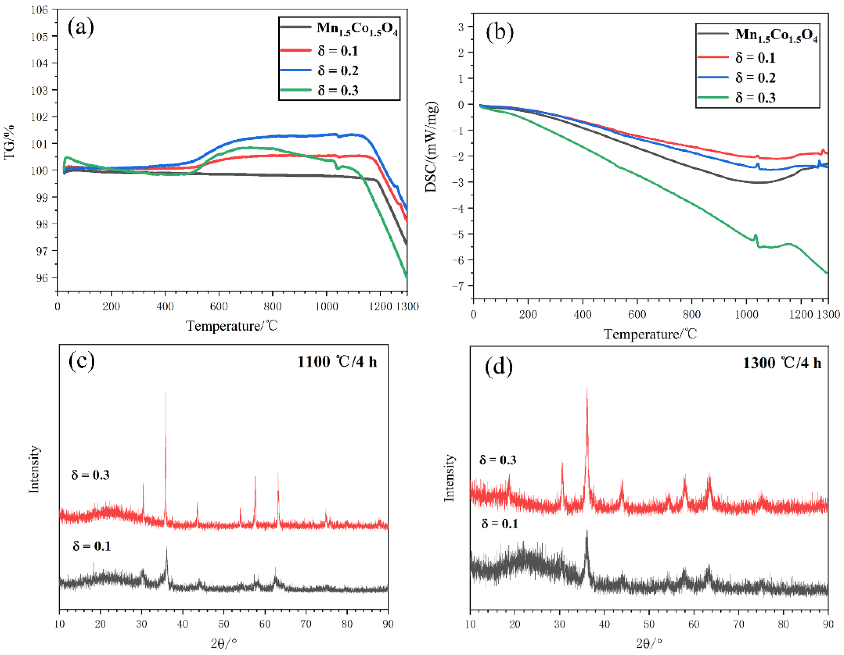
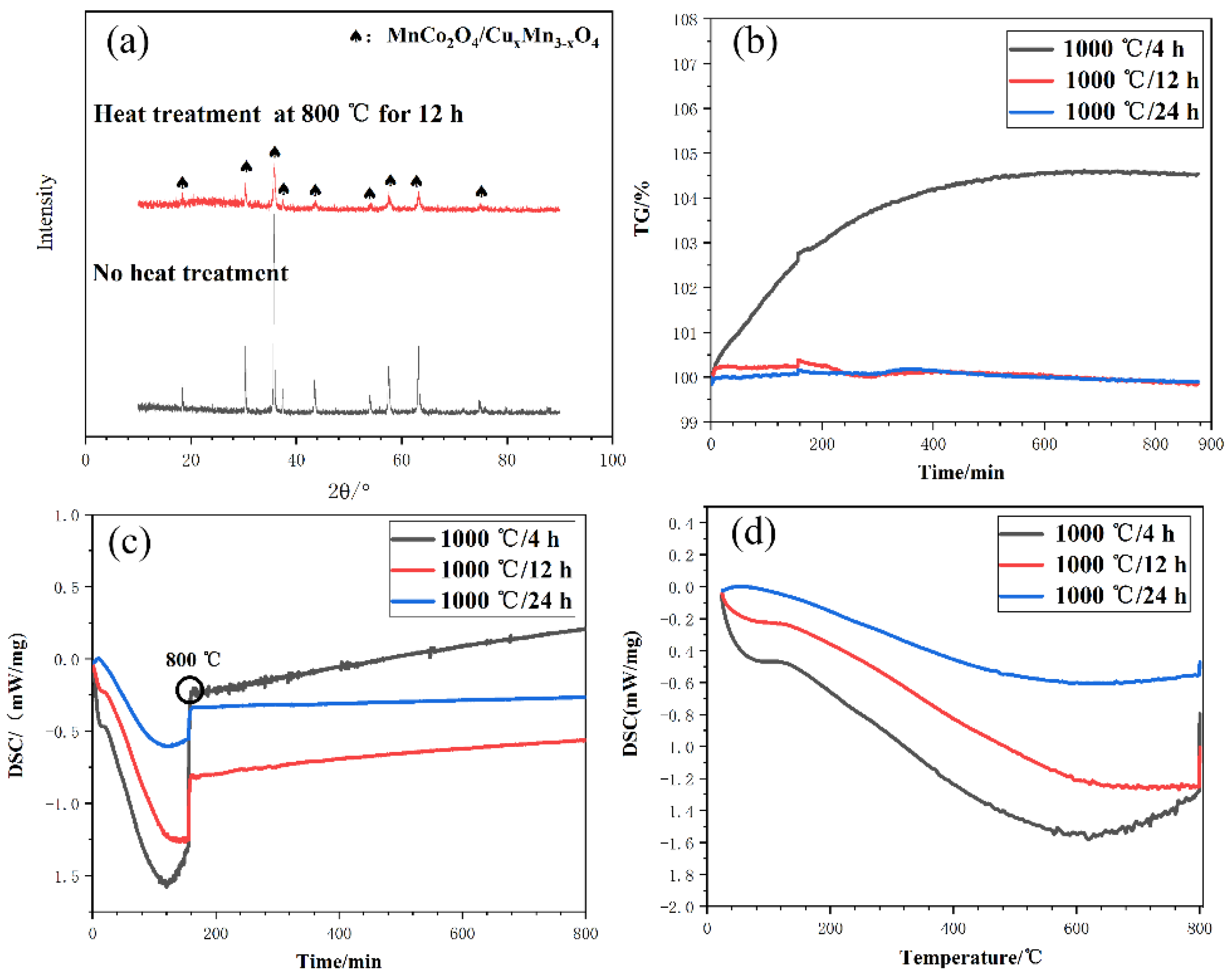
3.2. Solid Phase Reactions

CuδMn1.5−xCo1.5−yO4 (δ = 0, 0.1, 0.2, 0.3) powders were tested by TG-DSC to evaluate the physical and chemical changes during sintering. According to the TG curve in Figure 4a and the subsequent XRD analysis (Figure 5), it was found that the powders gained some weight at 500–800 °C, which was mainly attributed to the oxidization of Cu to CuO. However, at 800–1000 °C, the powder weights were found to decrease slightly and the CuO had disappeared. At 1034 °C, the powder weight was slightly decreased again, which might be related to the decomposition of the spinel phase. Then, the powder was found to lose weight violently between 1200–1300 °C, which indicates that the spinel phases were decomposed. As shown in Figure 4b, the commercial Mn1.5Co1.5O4 powder had no endothermic peak at 1034 °C, while CuδMn1.5−xCo1.5−yO4 (δ = 0.1, 0.2, 0.3) powder had an endothermic peak. According to public reports [9,13,20,21], the formation of CuxMn3-xO4 and MnCo2O4 is an exothermic process. Since the MnCo2O4 phase of the commercial Mn1.5Co1.5O4 powder showed no significant decomposition at 1034 °C, it was inferred that the endothermic peak at 1034 °C was the result of the decomposition of CuxMn3-xO4. Furthermore, in the range 1100–1300 °C, after increasing the amount of Cu, the TG curve shifted toward the left, and the stable temperature of the spinel phases decreased. The DSC curves were found to gradually flatten and continuously exhausted heat. As shown in Figure 4c,d, the Cu0.3Mn1.5−xCo1.5−yO4 powder exhibited the best crystallization. In conclusion, CuxMn3−xO4 spinel was successfully synthesized between 900 °C and 1034 °C. The powders with δ = 0.3 had the best crystallinity of spinel phases and consisted of more conductive spinel phase.

3.3. Sintering Conditions

Cu0.3Mn1.5−xCo1.5−yO4 powders were prepared at controlled sintering temperatures and durations. Cu was introduced into the spinel lattice by sintering. The more Cu that entered the spinel lattice, the better the conductivity of the coating. The phase composition, crystallization, and surface morphology of the prepared Cu0.3Mn1.5−xCo1.5−yO4 powders were specifically investigated. According to the XRD patterns of the powders sintered at 500–1300 °C for 4 h, it was found that, with the increase in sintering temperature, the abundance of CuO and (Co,Mn)(Co,Mn)2O4 phases reduced, while the abundance of MnCo2O4/CuxMn3−xO4 spinel phases increased. The crystallinity of the spinel phases increased firstly and then decreased as the temperature increased; thus, the best crystallization temperature was between 1000–1100 °C, as shown in Figure 5. According to the morphology of the sintered powders, the powder density was found to increase when the temperature increased from 900 °C to 1300 °C. After sintering between 1100–1300 °C, the powder was found to be severely agglomerated, as shown in Figure 6, while at 1000 °C, the powder porosity was reduced.
After sintering at 1000 °C for 2 h, 4 h, 8 h, 12 h, 16 h, and 24 h, the intensity of the diffraction peak and crystallinity of spinel were found to firstly increase and then decrease after 12 h. The change in diffraction peaks was related to the amount of spinel phases. The diffraction intensity of powder sintered for 12 h was the highest and the crystallinity was the best, as shown in Figure 5c,d. In Figure 7, EDS analysis showed a uniform distribution of Cu, which indicates that the Cu has been sucessfully doped into Mn1.5Co1.5O4 spinel powders. In conclusion, 1000 °C/12 h was the best condition for Cu doping.

3.4. Stability of Doped Powders

As Cu-Mn spinel is less stable than Mn-Co spinel at elevated temperature, when doping Mn-Co spinel with Cu to improve the conductivity, the stability of the obtained spinel is reduced. After being sintered at 1000 °C for 4 h, 12 h, and 24 h to allow the doping, the Cu0.3Mn1.5−xCo1.5−yO4 powder was heated to 800 °C and maintained in that state for 12 h to evaluate the stability. In Figure 8a, the XRD patterns before and after the heat treatment are presented. The MnCo2O4/CuxMn3−xO4 phase was detected after the heat treatment, but the diffraction intensity was significantly diminished. TG and DSC tests were performed from room temperature to 800 °C with a ramping rate of 5 °C/min, and a preservation stage of 12 h, in order to study the stability of the doped powders. It was found that during ramping, the DSC plots showed evident exothermic behavior. However, during the following preservation stage, both the TG and DSC curves exhibited a linear behavior in which no endothermic and exothermic peak was visible, as shown in Figure 8b–d. This indicates that the doped powder had a good stability during the preservation process. For the CuxMn3−xO4 powder, when x = 1.2, 1.4, 1.5, the CuO and spinel phase coexisted at 800 °C. However, according to the XRD and DSC patterns, it can be seen that the decomposition of CuxMn3−xO4 spinel did not occur and CuO was not formed. Therefore, the CuxMn3−xO4 phase was mainly composed of the CuMn2O4 phase. In conclusion, the MnCo2O4/CuMn2O4 phase in the powder can exist stably at 800 °C.

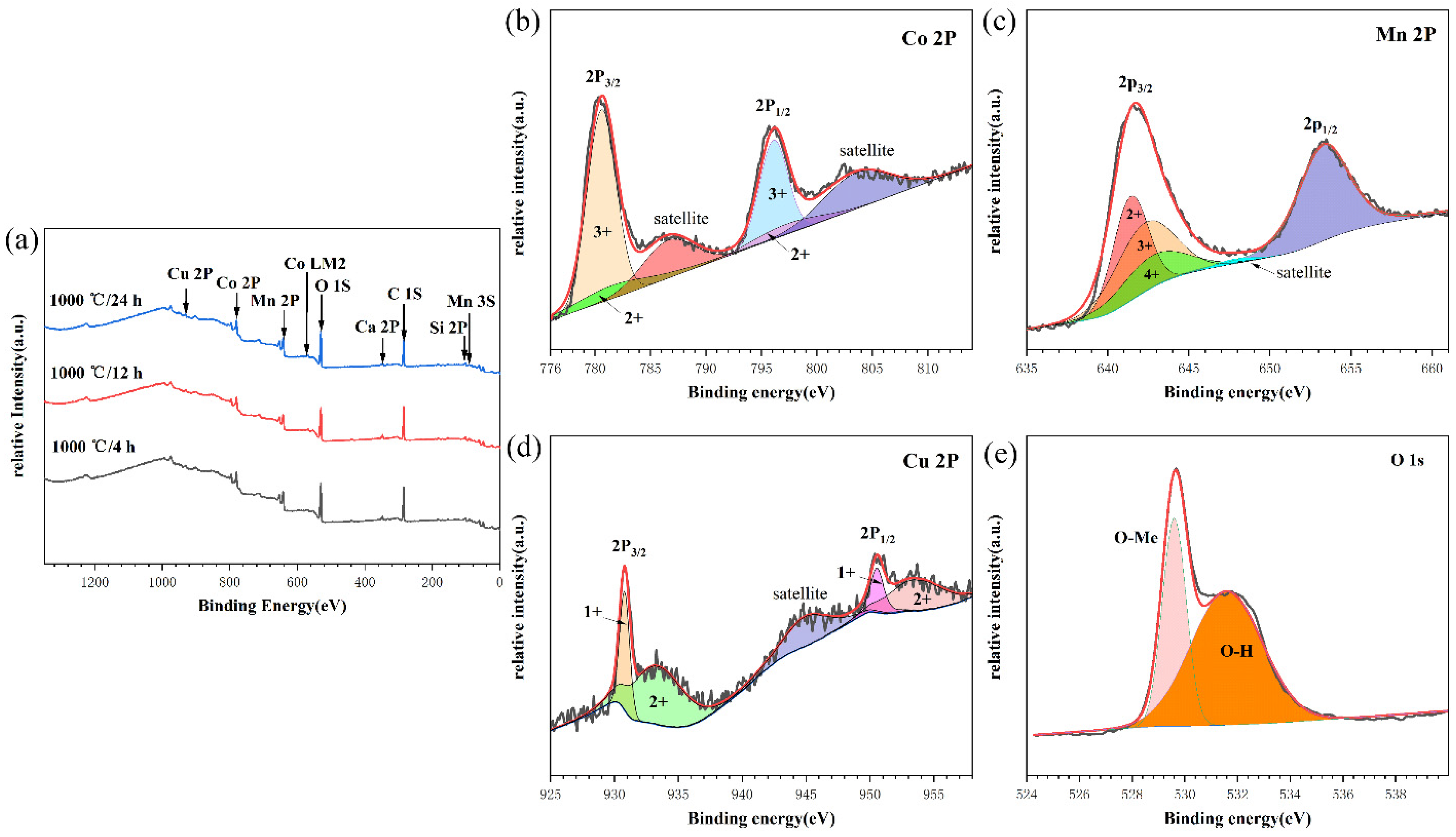
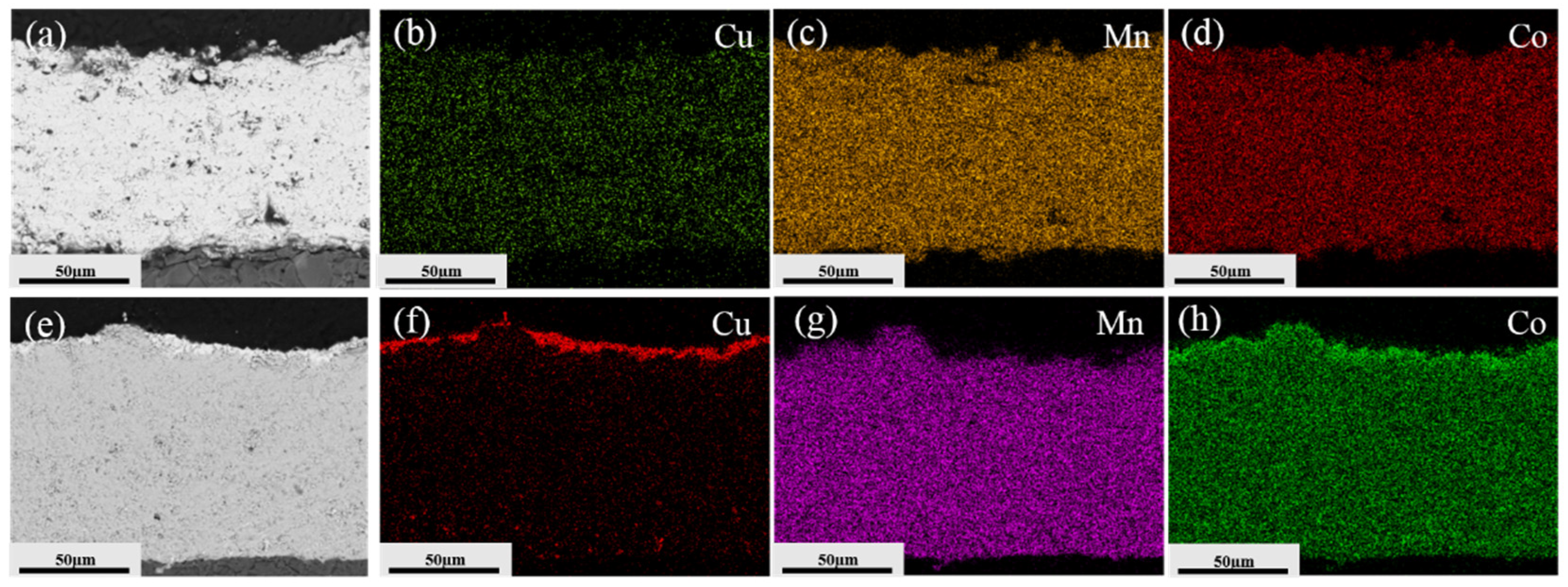
3.5. Elemental Composition

To determine the elemental composition and valence states of Cu0.3Mn1.5−xCo1.5−yO4 powders, XPS tests were carried out. As shown in Figure 9a, Co, Mn, Cu, O, and C were identified in the coating. According to the Co 2p spectrum in Figure 9b, the low-energy peaks (780.6 and 796.1 eV) and high-energy peaks (781.6 and 797.4 eV) in the Co 2P3/2 and 2P1/2 regions were ascribed to Co3+ and Co2+, respectively. In addition, the peaks with binding energies of 786.6 eV and 803.6 eV were identified as the satellite peaks of Co2+ and Co3+ [22,23,24]. As illustrated in Figure 9c, the peaks at 641.5, 642.3, and 642.8 eV corresponded to Mn2+, Mn3+, and Mn4+, respectively [25,26,27]. In Figure 9d, the peaks at 945 eV were attributed to Cu2+ satellites, while those at 930.8 and 933.4 eV were evidence of the presence of Cu+ and Cu2+ in the Cu 2P3/2 orbital peaks. Peaks at 953.5 and 950.6 eV can be assigned to the existence of Cu2+ and Cu+, which were observed in the Cu 2P1/2 orbital [28,29,30]. The peaks at 530.4 eV and 531.9 eV, as shown in Figure 9e, corresponded to the oxygen-metal bond (metal = Mn, Co) and O-H bond in the spinel phase, respectively [3].
According to public reports [10,31,32], various valences exist in Mn-Co-Cu spinel. By performing a deconvolution of the XPS spectra, the relative proportion of different valence states of elements can be obtained. The relative proportion is listed in Table 3. It was found that the relative proportion of Mn3+ increased to 41.3% when sintered for 12 h and then decreased 33.6% after 24 h of preservation. The areal fraction of Mn2+ and Co3+ increased first and then decreased when the sintering duration increased. The increase in Mn3+ indicated an increase in the CuMn2O4 phase, and the decrease in Mn2+ and Co3+ was related to the decomposition of the MnCo2O4 phase. Moreover, the increase in Mn4+ indicated an increase in MnO2, which diminished the conductivity of the prepared powders or coatings. According to Table 3 the powder prepared at 1000 °C and sintered for 12 h gave the most MnCo2O4 and CuMn2O4.

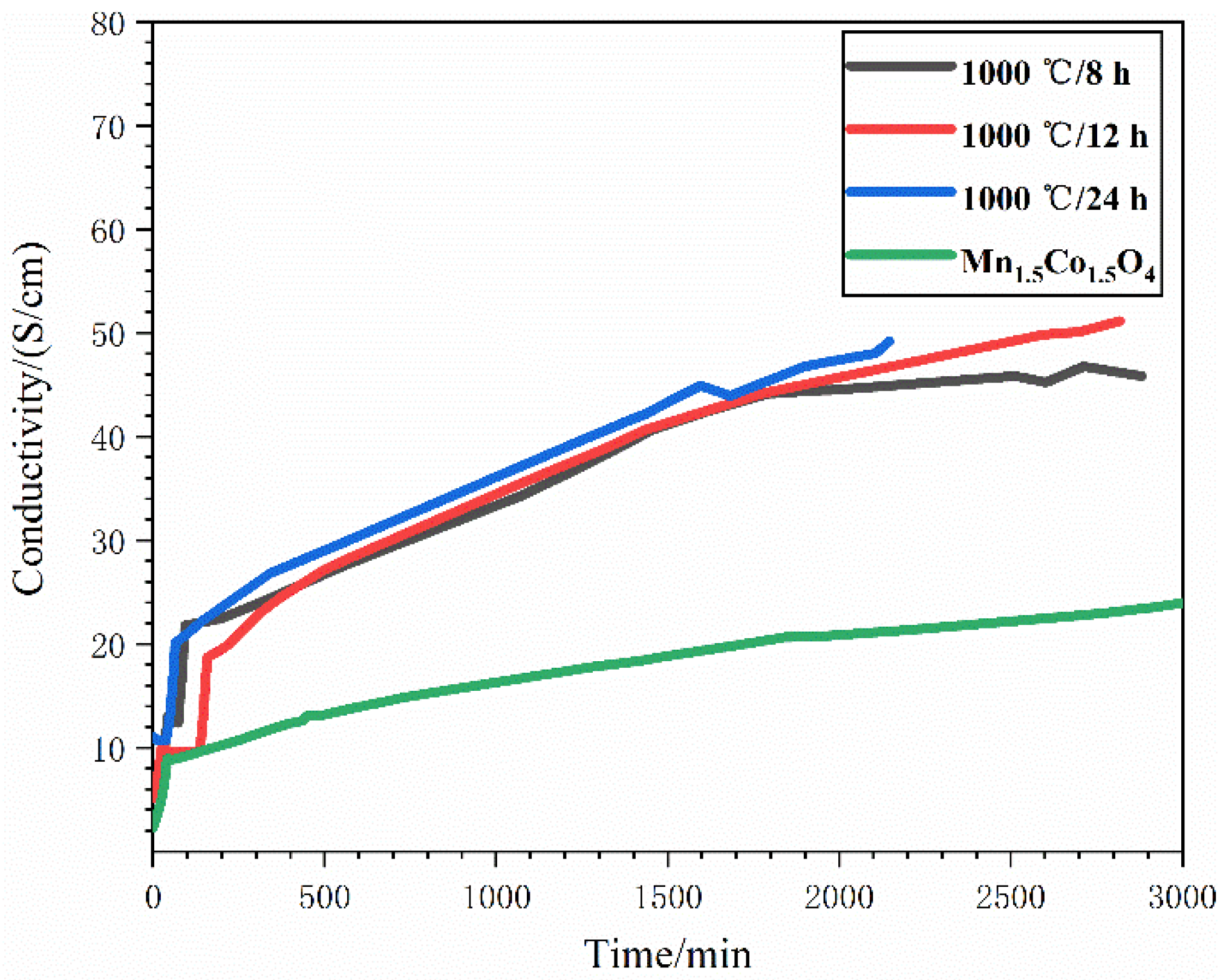
3.6. Coatings Conductivity

To evaluate the doping effect, commercial Mn1.5Co1.5O4 and Cu0.3Mn1.5−xCo1.5−yO4 powder (sintered at 1000 °C and maintained for 8 h, 12 h, and 24 h, respectively) were sprayed on Al2O3 sheets with an atmospheric plasma spray; the parameters are provided in Table 1. During spraying, the spinel powder was injected into the plasma plume, the temperature of which was as high as 15,000 °C, then the injected powder was heated, melted, accelerated, and impacted on the substrate to form coatings. Deoxidization and decomposition of the spinel powder occurred during spraying; therefore, low active phases such as MnO2 and CoO were generated and left in the coating. As a result of the very short spraying time, only a small part of the powder was decomposed, and most of the powder retained the spinel structure. Before the conductivity measurement, the sample was heated to 800 °C and maintained for 12 h to allow the densification of the coating and cure the decomposed phases. As shown in Figure 10, after the heat treatment, significant signals of MnCo2O4/CuMn2O4 were detected, which indicates a transference of low conductive phases to the spinel phase. For this reason, the measured coating conductivity increased with the temperature during preservation with a duration up to 50 h, as shown in Figure 11. The conductivity of the coating prepared with powder sintered for 12 h was about 51 S/cm after 47 h of preservation. For the coating prepared with powder sintered at 1000 °C for 8 h and 24 h, the conductivity was 45 S/cm and 49.2 S/cm, respectively, which are more than double that of the Mn1.5Co1.5O4 coating, 23 S/cm after 50 h of preservation. Therefore, by applying Cu doping, the conductivity of Mn-Co spinel coatings can be significantly improved. Moreover, according to Figure 10 and Figure 11, the coating prepared with powder sintered at 1000 °C for 8 h exhibited lower crystallinity and less spinel content, resulting in a coating conductivity lower than that of the 1000 °C/12 h and 24 h samples.
The sectional morphology and element distribution before and after the conductivity measurement of the best coating (1000 °C for 12 h) are provided in Figure 12. After the conductivity measurement, the coating was significantly densified, and no large pores or cracks were visible on the cross-section. The distribution of Mn and Co exhibited no evident variation, while Cu was found to be enriched on the coating surface. The enriched Cu on the surface was then oxidized to CuO at 800 °C, which limited the conductivity of the coatings. Despite the existence of CuO on the surface restraining the doping effect, Cu doping remains a convenient method to significantly promote the conductivity of spinel coatings for SOFC applications.

4. Conclusions

The powder CuδMn1.5−xCo1.5−yO4 (x + y = δ) with δ = 0.3 showed a better performance than the powder with δ = 0.1 or 0.2. The results of XRD and TG-DSC indicated that increasing the dopant amount resulted in an enhanced doping effect. With δ = 0.3, the powder had a better crystallinity and a more conductive spinel phase.
The best doping condition for Cu0.3Mn1.5−xCo1.5−yO4 powders was 1000 °C for 12 h. Under this condition, the crystallization of the spinel phase (MnCo2O4 and CuxMn3−xO4) was the best and the powder was moderately dense. The dopant Cu was found to be evenly distributed in the powders. The CuxMn3−xO4 (x = 1, 1.2, 1.4 or 1.5) was found to be mainly composed of CuMn2O4 and was sufficiently stable at elevated temperatures. According to the XPS results, the powder prepared at 1000 °C for 12 h consisted of the most MnCo2O4 and CuMn2O4. When the preservation stage was conducted at 1000 °C with a duration of less than 12 h or more than 12 h, less MnCo2O4 and CuxMn3−xO4 phases were detected.
Coatings were prepared with doped powders using an atmospheric plasma spray. After preservation at 800 °C for a duration of up to 50 h, the measured conductivity of the prepared coatings reached 45 S/cm, 51 S/cm, and 49.2 S/cm, respectively, i.e., two times more than that of the Mn1.5Co1.5O4 coating (23 S/cm). Although Cu was enriched on the coating surface after the conductivity measurement, Cu-doping is still an effective method to improve the conductivity of spinel coatings used for interconnect protection in SOFC.

Author Contributions

Formal analysis, Z.J.; investigation, Z.J. and C.S.; methodology, K.W. and T.L.; project administration, M.L.; resources, C.D. (Changguang Deng); supervision, C.D. (Chunming Deng) and Y.D.; writing—original draft, Z.J.; writing—review and editing, T.L. and C.Y. All authors have read and agreed to the published version of the manuscript.

Funding

This research was funded by the National Key R&D Program of China grant number 2018YFB1502603, Guangdong Academy of Science grant number 2019GDASYL-0102007, the Foreign Cooperation Platform Project of Guangdong Province grant number 2020A050519001, and Guangzhou Major Projects of Industry-University-Research (IUR) Collaborative Innovation “Surface Treatment and Repair for Key Components of Industrial Gas Turbine (IGT)”.

Institutional Review Board Statement

Not applicable.

Informed Consent Statement

Not applicable.

Data Availability Statement

The data presented in this study are available on request from the corresponding author.

Conflicts of Interest

The authors declare no conflict of interest. The founding sponsors had no role in the design of the study; in the collection, analyses, or interpretation of data; in the writing of the manuscript, and in the decision to publish the results.

References

  1. Shong, W.J.; Liu, C.K.; Chen, C.Y.; Peng, C.C.; Tu, H.J.; Fey, G.T.K.; Lee, R.Y.; Kao, H.M. Effects of lanthanum-based perovskite coatings on the formation of oxide scale for ferritic SOFC interconnect. Mater. Chem. Phys. 2011, 127, 45–50. [Google Scholar] [CrossRef]
  2. Stanislowski, M.; Froitzheim, J.; Niewolak, L.; Quadakkers, W.J.; Hilpert, K.; Markus, T.; Singheiser, L. Reduction of chromium vaporization from SOFC interconnectors by highly effective coatings. J. Power Sources 2007, 164, 578–589. [Google Scholar] [CrossRef]
  3. Zou, J.; Song, C.; Wen, K.; Liu, T.; Deng, C.; Liu, M.; Yang, C. The Microstructure and Conductivity Evolution of Plasma-Sprayed (Mn, Co)3O4 Spinel Coatings during Conductivity Measurements at Elevated Temperature. Coatings 2021, 11, 533. [Google Scholar] [CrossRef]
  4. Grünwald, N.; Sohn, Y.J.; Yin, X.; Menzler, N.H.; Guillon, O.; Vaßen, R. Microstructure and phase evolution of atmospheric plasma sprayed Mn-Co-Fe oxide protection layers for solid oxide fuel cells. J. Eur. Ceram. Soc. 2019, 39, 449–460. [Google Scholar] [CrossRef]
  5. Xin, X.; Zhu, Q.; Liu, Y. Conductive protective coating with heat oxygen-resistance for solid oxide fuel cell (SOFC) alloy interconnect. Surf. Technol. 2019, 48, 22–29. [Google Scholar] [CrossRef]
  6. Jiang, S.P. Development of lanthanum strontium cobalt ferrite perovskite electrodes of solid oxide fuel cells-A review. Int. J. Hydrogen Energy. 2019, 44, 7448–7493. [Google Scholar] [CrossRef]
  7. Tan, K.H.; Rahman, H.A.; Taib, H. Coating layer and influence of transition metal for ferritic stainless steel interconnector solid oxide fuel cell: A review. Int. J. Hydrogen Energy 2019, 44, 30591–30605. [Google Scholar] [CrossRef]
  8. Mah, J.C.W.; Muchtar, A.; Somalu, M.R.; Ghazali, M.J. Metallic interconnects for solid oxide fuel cell: A review on protective coating and deposition techniques. Int. J. Hydrogen Energy 2017, 42, 9219–9229. [Google Scholar] [CrossRef]
  9. Waluyo, N.S.; Park, S.S.; Song, R.H.; Lee, S.-B.; Lim, T.-H.; Hong, J.-E.; Ryu, K.H.; Bin Im, W.; Lee, J.-W. Protective coating based on manganese–copper oxide for solid oxide fuel cell interconnects: Plasma spray coating and performance evaluation. Ceram. Int. 2018, 44, 11576–11581. [Google Scholar] [CrossRef]
  10. Talic, B.; Hendriksen, P.V.; Wiik, K.; Lein, H.L. Thermal expansion and electrical conductivity of Fe and Cu doped MnCo2O4 spinel. Solid State Ion. 2018, 326, 90–99. [Google Scholar] [CrossRef]
  11. Talic, B.; Hendriksen, P.V.; Wiik, K.; Lein, H.L. Diffusion couple study of the interaction between Cr2O3 and MnCo2O4 doped with Fe and Cu. Solid State Ion. 2019, 332, 16–24. [Google Scholar] [CrossRef]
  12. Puranen, J.; Pihlatie, M.; Lagerbom, J.; Bolelli, G.; Laakso, J.; Hyvärinen, L.; Kylmälahti, M.; Himanen, O.; Kiviaho, J.; Lusvarghi, L.; et al. Post-mortem evaluation of oxidized atmospheric plasma sprayed Mn–Co–Fe oxide spinel coatings on SOFC interconnectors. Int. J. Hydrogen Energy 2014, 39, 17284–17294. [Google Scholar] [CrossRef]
  13. Liu, Y.; Fergus, J.W.; Wang, K.; Cruz, C.D. Crystal Structure, Chemical Stabilities and Electrical Conductivity of Fe-Doped Manganese Cobalt Spinel Oxides for SOFC Interconnect Coatings. J. Electrochem. Soc. 2013, 160, F1316–F1321. [Google Scholar] [CrossRef]
  14. Zhu, J.H.; Lewis, M.J.; Du, S.W.; Li, Y. CeO2-doped (Co,Mn)3O4 coatings for protecting solid oxide fuel cell interconnect alloys. Thin Solid Films 2015, 596, 179–184. [Google Scholar] [CrossRef] [Green Version]
  15. Tseng, H.P.; Yung, T.Y.; Liu, C.K.; Cheng, Y.-N.; Lee, R.-Y. Oxidation characteristics and electrical properties of La- or Ce-doped MnCo2O4 as protective layer on SUS441 for metallic interconnects in solid oxide fuel cells. Int. J. Hydrogen Energy 2020, 45, 12555–12564. [Google Scholar] [CrossRef]
  16. Gavrilov, N.V.; Ivanov, V.V.; Kamenetskikh, A.S.; Nikonov, A. Investigations of Mn–Co–O and Mn–Co–Y–O coatings deposited by the magnetron sputtering on ferritic stainless steels. Surf. Coat. Technol. 2011, 206, 1252–1258. [Google Scholar] [CrossRef]
  17. Brylewski, T.; Kruk, A.; Bobruk, M.; Adamczyk, A.; Partyka, J.; Rutkowski, P. Structure and electrical properties of Cu-doped Mn-Co-O spinel prepared via soft chemistry and its application in intermediate-temperature solid oxide fuel cell interconnects. J. Power Sources 2016, 333, 145–155. [Google Scholar] [CrossRef]
  18. Xu, Y.; Wen, Z.; Wang, S.; Wen, T. Cu doped Mn–Co spinel protective coating on ferritic stainless steels for SOFC interconnect applications. Solid State Ion. 2011, 192, 561–564. [Google Scholar] [CrossRef]
  19. Sabato, A.G.; Molin, S.; Javed, H.; Zanchi, E.; Boccaccini, A.R.; Smeacetto, F. In-situ Cu-doped MnCo-spinel coatings for solid oxide cell interconnects processed by electrophoretic deposition. Ceram. Int. 2019, 45, 19148–19157. [Google Scholar] [CrossRef]
  20. Wei, P.; Bieringer, M.; Cranswick, L.M.D.; Petric, A. In situ high-temperature X-ray and neutron diffraction of Cu–Mn oxide phases. J. Mater. Sci. 2010, 45, 1056–1064. [Google Scholar] [CrossRef] [Green Version]
  21. Masi, A.; Bellusci, M.; McPhail, S.J.; Padella, F.; Reale, P.; Hong, J.-E.; Steinberger-Wilckens, R.; Carlini, M. Cu-Mn-Co oxides as protective materials in SOFC technology: The effect of chemical composition on mechanochemical synthesis, sintering behaviour, thermal expansion and electrical conductivity. J. Eur. Ceram. Soc. 2017, 37, 661–669. [Google Scholar] [CrossRef]
  22. Waskowska, A.; Gerward, L.; Olsen, J.S.; Steenstrup, S.; Talik, E. CuMn2O4: Properties and the high-pressure induced Jahn-Teller phase transition. J. Phys. Condens. Matter 2001, 13, 2549–2562. [Google Scholar] [CrossRef]
  23. Hu, Y.Z.; Su, Y.T.; Li, C.X.; Li, C.-J.; Yang, G.-J. Dense Mn1.5Co1.5O4 coatings with excellent long-term stability and electrical performance under the SOFC cathode environment. Appl. Surf. Sci. 2020, 499, 143726. [Google Scholar] [CrossRef]
  24. Fan, L.Q.; Huang, J.L.; Wang, Y.L.; Geng, C.-L.; Sun, S.-J.; Huang, Y.-F.; Lin, J.-M.; Wu, J.-H. TiO2 nanotubes supported ultrafine MnCo2O4 nanoparticles as a superior-performance anode for lithium-ion capacitors. Int. J. Hydrogen Energy 2021, 46, 35330–35341. [Google Scholar] [CrossRef]
  25. Li, J.; Xiong, S.; Li, X.; Qian, Y. A facile route to synthesize multiporous MnCo2O4 and CoMn2O4 spinel quasi-hollow spheres with improved lithium storage properties. Nanoscale 2013, 5, 2045–2054. [Google Scholar] [CrossRef]
  26. Umezawa, Y.; Reilley, C.N. Effect of argon ion bombardment on metal complexes and oxides studied by x-ray photoelectron spectroscopy. Anal. Chem. 1978, 50, 1290–1295. [Google Scholar] [CrossRef]
  27. Vepřek, S.; Cocke, D.L.; Kehl, S.; Oswald, H.R. Mechanism of the deactivation of Hopcalite catalysts studied by XPS, ISS, and other techniques. J. Catal. 1986, 100, 250–263. [Google Scholar] [CrossRef]
  28. Liu, Y.; Song, Z.; Wang, W.; Wang, Z.; Zhang, Y.; Liu, C.; Wang, Y.; Li, A.; Xu, B.; Qi, F. A CuMn2O4/g-C3N4 catalytic ozonation membrane reactor used for water purification: Membrane fabrication and performance evaluation. Sep. Purif. Technol. 2021, 265, 118268. [Google Scholar] [CrossRef]
  29. Fang, R.; Liu, F.; Liu, J.; Li, Y. Experimental and theoretical insights into the reaction mechanism of spinel CuMn2O4 with CO in chemical-looping combustion. Appl. Surf. Sci. 2021, 561, 150065. [Google Scholar] [CrossRef]
  30. Thaheem, I.; Joh, D.W.; Noh, T.; Lee, K.T. Highly conductive and stable Mn1.35Co1.35Cu0.2Y0.1O4 spinel protective coating on commercial ferritic stainless steels for intermediate-temperature solid oxide fuel cell interconnect applications. Int. J. Hydrogen Energy 2019, 44, 4293–4303. [Google Scholar] [CrossRef]
  31. Bobruk, M.; Durczak, K.; Dąbek, J.; Dąbek, J.; Brylewski, T. Structure and Electrical Properties of Mn-Cu-O Spinels. J. Mater. Eng. Perform. 2017, 26, 1598–1604. [Google Scholar] [CrossRef] [Green Version]
  32. Joshi, S.; Petric, A. Nickel substituted CuMn2O4 spinel coatings for solid oxide fuel cell interconnects. Int. J. Hydrogen Energy 2017, 42, 5584–5589. [Google Scholar] [CrossRef]
Figure 1. The morphology of Cu powder (a) and Mn1.5Co1.5O4 powder (b).
Coatings 11 01298 g001
Figure 2. Illustration of the conductivity measurements setup.
Coatings 11 01298 g002
Figure 3. XRD patterns of Mn1.5Co1.5O4 powder and CuδMn1.5−0.5xCo1.5−0.5xO4 powder.
Coatings 11 01298 g003
Figure 4. (a) TG curves of CuδMn1.5−xCo1.5−yO4 powders; (b) DSC curve; (c) XRD patterns of powder sintered at 1100 °C for 4 h with δ = 0.1 and 0.3; (d) XRD patterns of powder sintered at 1300 °C for 4 h with δ = 0.1 and 0.3.
Coatings 11 01298 g004
Figure 5. XRD patterns of doped powders sintered under different conditions: (a,b) 500–1300 °C for 4 h; (c,d) 1000 °C for 2–24 h.
Coatings 11 01298 g005
Figure 6. The morphology of Cu0.3Mn1.5−xCo1.5−yO4 powders sintered at: (a) 900 °C for 12 h; (b) 1000 °C for 12 h; (c) 1000 °C for 12 h (cross-sectional); (d) 1100 °C for 4 h; (e) 1300 °C for 4 h; (f) 1100 °C for 4 h (cross-sectional).
Coatings 11 01298 g006
Figure 7. The morphology and elements distribution of Cu0.3Mn1.5−xCo1.5−yO4 powders sintered at 1000 °C for 12 h (ad) low magnification; (eh) high magnification.
Coatings 11 01298 g007
Figure 8. (a) XRD patterns before and after heating at 800 °C of powder sintered at 1000 °C for 12 h; (b,c) TG-DSC curves of powders sintered at 1000 °C for 4 h, 12 h, and 24 h; (d) DSC curves during the heating process.
Coatings 11 01298 g008
Figure 9. XPS spectra of Cu0.3Mn1.5−xCo1.5−yO4 powders sintered at 1000 °C: (a) survey; (b) Co 2P of 1000 °C/12 h sample; (c) Mn 2P of 1000 °C/12 h sample; (d) Cu 2P of 1000 °C/12 h sample; (e) O 1s of 1000 °C/12 h sample.
Coatings 11 01298 g009
Figure 10. XRD patterns of coatings prepared with sintering powder for different times: (a) spray state; (b) coatings at 800 °C for 50 h.
Coatings 11 01298 g010
Figure 11. Coatings conductivity prepared from commercial spinel powder and Cu0.3Mn1.5−xCo1.5−yO4.
Coatings 11 01298 g011
Figure 12. Morphologies and compositions of Cu0.3Mn1.5−xCo1.5−yO4 coating: (ad) before the conductivity measurement; (eh) after the conductivity measurement.
Coatings 11 01298 g012
Table 1. The raw material ratio to prepare CuδMn1.5−xCo1.5−yO4 powders.
Mass Percentage (wt%)δ = 0.1δ = 0.2δ = 0.3
Cu Powder2.75.48.0
Mn1.5Co1.5O4 Power97.394.692.0
Table 2. Spray parameters to prepare Cu-doped Mn-Co spinel coatings.
Gas Flow (NL/min)Current (A)Gun Speed (mm/s)Powder Feeding Rate (g/min)Spray Distance (mm)
Ar/72H2/862080015110
Table 3. Areal fractions of Mn and Co in the powders prepared under different conditions.
Element StateAreal Fraction (%)
1000 °C/4 h1000 °C/8 h1000 °C/12 h1000 °C/24 h
Mn2+32.346.236.734.2
Mn3+31.733.241.333.6
Mn4+36.020.622.032.2
Co2+23.620.917.726.3
Co3+76.479.182.373.7
Publisher’s Note: MDPI stays neutral with regard to jurisdictional claims in published maps and institutional affiliations.

