Article

Control of the Mg-Treated Iron Casting Skin Formation by S-Diffusion Blocking at the Metal–Mould Interface

Materials Science and Engineering Faculty, Politehnica University of Bucharest, 313 Spl. Independentei, 060042 Bucharest, Romania
*
Author to whom correspondence should be addressed.
Coatings 2020, 10(7), 680; https://doi.org/10.3390/coatings10070680
Submission received: 1 July 2020 / Revised: 10 July 2020 / Accepted: 12 July 2020 / Published: 15 July 2020
(This article belongs to the Special Issue Surface Treatment of Metals)

Abstract

:
Having established that sulphur presence in the mould materials appears to have an important contribution in graphite degeneration at least in the casting surface layer, a research program is undertaken to explore the possible beneficial effect of sulphur diffusion blocking at the metal–mould interface. Test samples, with and without a thin steel sheet (up to 3 mm thickness) application on the inner surface of the mould cavity, before iron melt pouring, are considered for structure analysis. A higher nodulizing potential (0.048% Mgres, 0.015% Ceres, and 0.006% Lares) decreases the occurrence of surface graphite degeneration in castings obtained in rigid chemically bonded resin sand moulds, using P-toluol sulfonic acid (PTSA) hardener (S-including), but it is not enough to avoid this phenomenon (200–400 μm skin in present experimental conditions). The casting skin appears to have different values, depending on the evaluation technique (un- and Nital-etching direct measurement, or graphite parameters variation on the casting section). In the presence of a thin steel sheet at the metal–mould interface, the casting skin thickness decreases or is just excluded. It is supposed that it acts as a barrier, blocking S-diffusion from the mould media into the iron melt. Without this S-diffusion, the graphite degeneration in the casting surface layer could be avoided, or at least diminished. For industrial application, the increasing of residual content of nodulizing elements is a limited solution, and it is recommended to use barriers to block S transfer on the mould/metal surface, such as dense coatings or coatings with desulphurization capacity.

1. Introduction

According to Modern Casting Journal census [1], the world casting production in 2018 was over than 112 million metric tons, including around 70% cast iron, 10% cast steel, and 20% non-ferrous (17% Al) castings, respectively. The global iron cast production rose from 54.5 million metric tons in the year 2000 to over 85 million tons in 2017. Between 2000 and 2017, the output of grey iron cast rose by around 40%, while the production volume of ductile iron cast doubled worldwide to around 27 million tons [2]. A total of 16.8 M tons of the world production was casted in CAEF (The European Foundry Association). The iron, steel, and malleable foundries of the CAEF member states produce approximately 12.3 M tons of castings per year. The share of cast iron with lamellar graphite in the output total of iron and steel castings is 50%, correspondingly, the share of ductile cast iron is slightly higher (43.7%). The steel sector logs a share of 6.4% [3].
In automotive power-train trends and the market opportunity for cast iron for the automotive industry analysis, S. Dawson concluded that the cast iron foundry industry could play an active role in guiding legislators and educating consumers on the need to consider the entire life cycle production of the vehicle, and production, delivery, and consumption of the fuel. In this way, cast iron position in the automotive industry has to be revised, compared with apparently more attractive, light Al alloys [4].
A solution for the cast iron industry to be competitive with aluminium alloys is to produce thin wall ductile iron (TWDI) castings, generally less than 5 mm section size. TWDI castings can be lighter than their substitute made of aluminium alloys and characterize similar or better mechanical properties, and definitely better dumping capacity. Economically, the costs involved in producing ductile iron are much lower than those corresponding to Al alloys. All the technological aspects involved in the production of thin wall ductile iron castings should have been worked out before considering the development aluminium alloys castings as cast iron substitutes [5].
The properties of the ductile/compacted graphite iron castings generally, and of the thin wall ductile/compacted graphite iron castings especially, are affected by graphite degradation layer formation, with fatigue properties being more sensitive to surface condition than the static properties [6,7,8,9,10]. It is found that compacted graphite cast iron is more susceptible to the casting skin effect than grey and ductile cast irons [6,7,8,9,11,12,13,14].
Green sand moulds, as less rigid moulds, compared with resin sand moulds, encourage the formation of contraction defects, not only because of high initial expansion values, but also because of a higher cooling rate during solidification, and increasing undercooling below the metastable equilibrium temperature up to the end of solidification [15,16].
Consequently, in the world foundry industry, ductile iron castings are usually produced in rigid moulds, typically as chemically bonded sand moulds (self-set, no-bake, cold box) using P-toluol sulfonic acid (PTSA) hardener (including sulphur). Furan acid and phenolic catalyst systems are particularly attractive to ductile iron producers as these binder systems produce very strong, rigid moulds. Strong moulds are a prerequisite for directly applied and/or riser-less design feeding systems, being less sensitiveness to shrinkage and micro-shrinkage formation. Although resin mould technology is popular for ductile iron casting production, it can also contribute to graphite degeneration at the surface of spheroidal graphite cast iron.

2. Background

The degenerated graphite layer (skin) formation at the surface of the Mg-treated iron castings is generally accepted to be produced by chemical reactions between nodulizing elements from the iron melt (Mg, Ce, La) and active elements supplied by mould and core materials (sulphur, oxygen, nitrogen, moisture), mould and core coatings, and gaseous atmosphere in the mould cavity [6,7,8,9,10,11,12,13,14,15,16,17].
Sulphur appears to be the most important contributor in graphite degeneration in the casting surface layer, originating in the mould and core materials or in the applied coatings on the mould or/and core, in order to improve the quality of the casting surface, avoiding adherence and reducing the iron casting roughness.
Previous research programs pointed out the major role of sulphur, supposed to be supplied by mould materials or mould coatings, before Mg-treated iron casting solidification [13,14,15,17,18,19,20]. Figure 1 [13] summarizes the effect of final residual magnesium in the Mg-treated iron castings, solidified in ceramic mould without sulphur contribution (Novolak resin sand mould—NRS mould) or with sulphur content (resin sand with P-toluol sulfonic acid (PTSA) hardener, Furan Resin Sand (FRS)-PTSA mould). For the both mould media, un-coating and mould coating moulds are tested. The applied coatings include sulphur bearing materials or MgO bearing material.
The most important conclusions of these research programs are as follows:
(a)
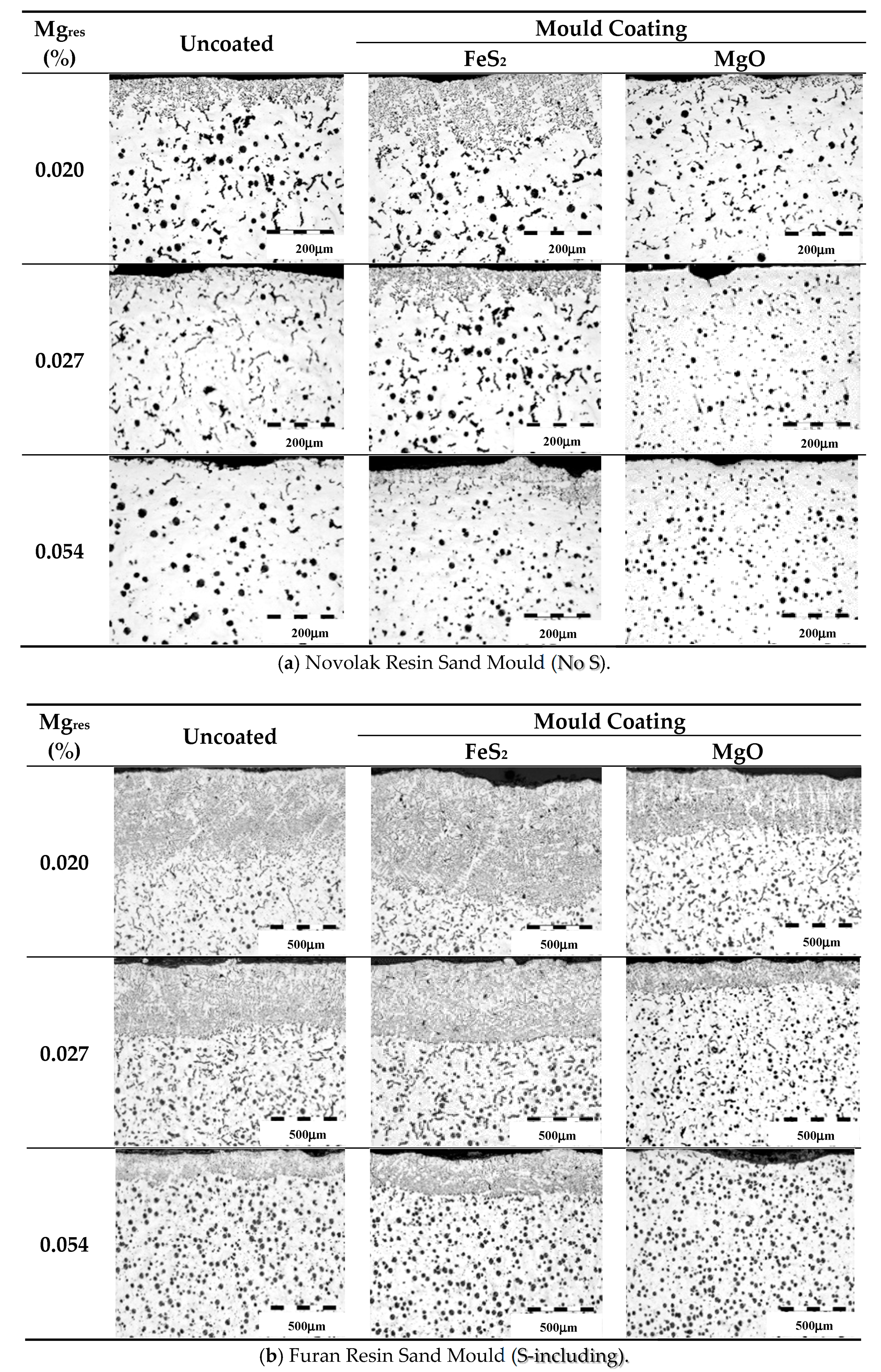
Uncoated FRS-PTSA moulds with sulphur in the binder promoted degenerate graphite in the surface layer of the test castings, with the thickness of this layer increasing more than five times compared with NRS moulds (no mould sulphur), but also strongly depending on residual magnesium content.
(b)
With lower Mg content, more graphite degeneration is apparent in the cast surface layer, especially at less than 0.03% Mgres (typical Mg content for vermicular/compacted graphite cast irons) with increasing differences between FRS-PTSA and NRS moulds, and uncoated and coated moulds results.
(c)
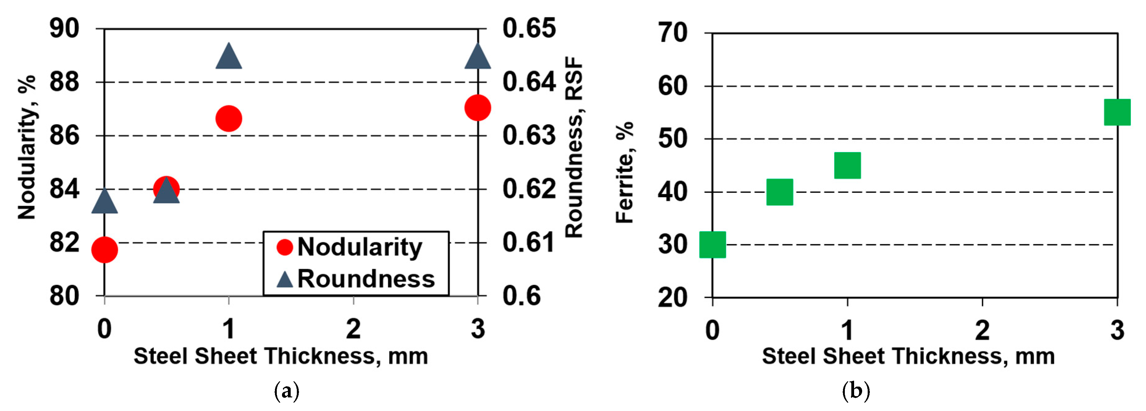
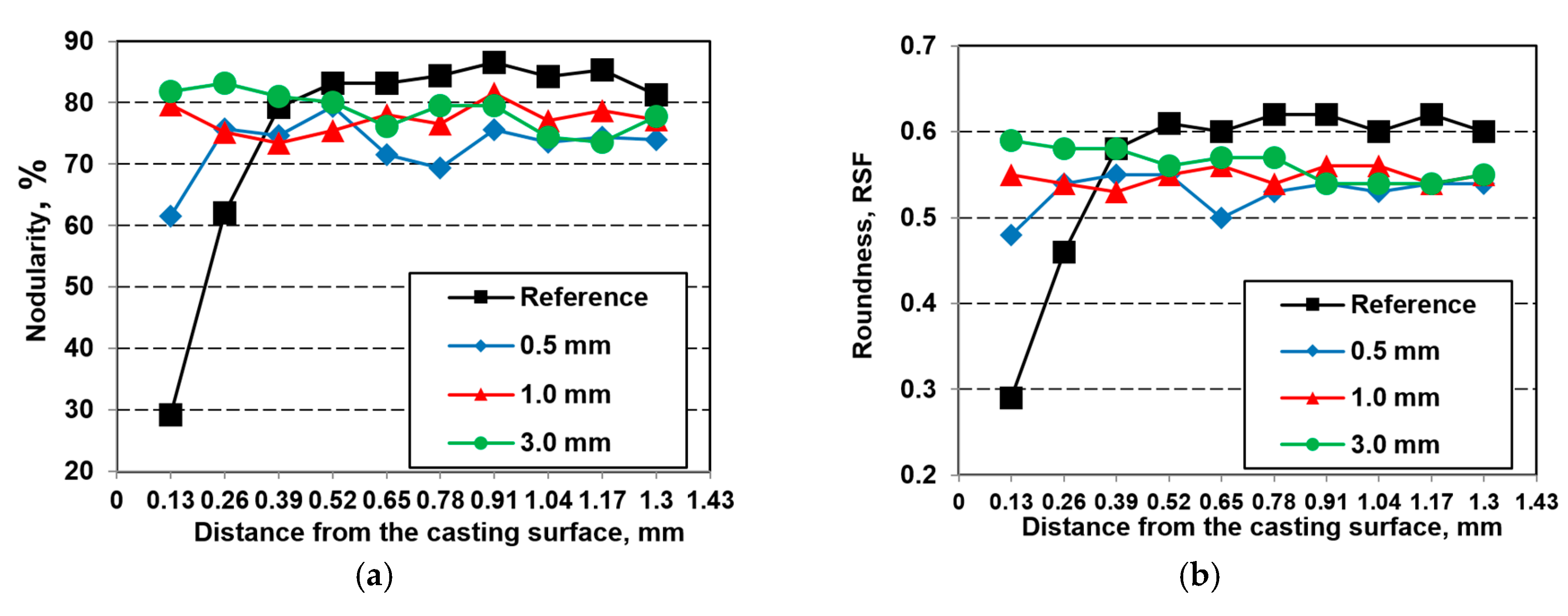
The graphite characteristics (nodularity, shape factor, aspect ratio) in the centre of the analysed samples evolved in a clear relationship with the changes in the degenerate graphite surface layer, for the prevailing solidification conditions: higher surface layer thickness, lower is the graphite nodularity in the casting body.
(d)
Comparing the graphite morphologies in irons solidified against different mould coatings, it appears that application of the coatings mainly controlled the chemical interactions between S and Mg and rare earth elements (REE), rather than affecting heat transfer.
(e)
Sulphur bearing coatings increase the surface layer thickness by up to five times in NRS moulds and by 50% in FRS-PTSA moulds, by augmenting the sulphur already present in the FRS-PTSA moulds.
(f)
The coatings based on desulphurizer type materials, such as MgO, provide some protection at the metal–mould interface. It is assumed that this coating behaves as a desulphurizer locally and counters the negative effect of sulphur released by the mould.
(g)
An effective coating designed to protect Mg-treated iron casting must go beyond the role of desulphurizing with supplementary Mg to preserve graphite nodularity. This dual activity is achieved with coatings containing active Mg, derived from (Mg) FeSi materials [17,18,19,20].
Xiaogan [21] suggested that graphite degeneration is caused at the surface by SO2 from the combustion of PTSA in the resin-bonded sand at casting temperatures. SO2 is absorbed at the metal surface, where it dissociates into atoms allowing diffusion into the molten metal, to form sulphides of the reactive elements, Mg, rare earth elements (REEs), and Mn.
On the basis of technical literature and appropriate experiments, the following policies are recommended for FRS-PTSA moulding lines to control the abnormal surface layer formation [14]: the sulphur content should be less than 0.15 wt.% S in the mould (or even <0.07 wt.% S); reduce the PTSA content, ideally to less than 50 wt.% of the resin; reduce reclaimed sand usage, usually less than 70 wt.%; use well maintained and calibrated mixers; use effective size classification in reclaimed sand systems; blend phosphoric acid with the PTSA, but be aware this may lead to P pick-up; increase the nodulizer addition (with attendant risk to the casting quality), and this usually will not eliminate the defects; lower the pouring temperature, usually less than 1350 °C (depending on casting weight and predominant section size); and use mould coatings with a desulphurization capability, such as a CaO/MgO/Talc composition, and especially similar coatings with Mg-bearing FeSi in the mix.
Having established that sulphur presence in the mould materials appears to have an important contribution in graphite degeneration at least in the casting surface layer, a research program is undertaken to explore the possible beneficial effect of sulphur diffusion blocking at the metal–mould interface.

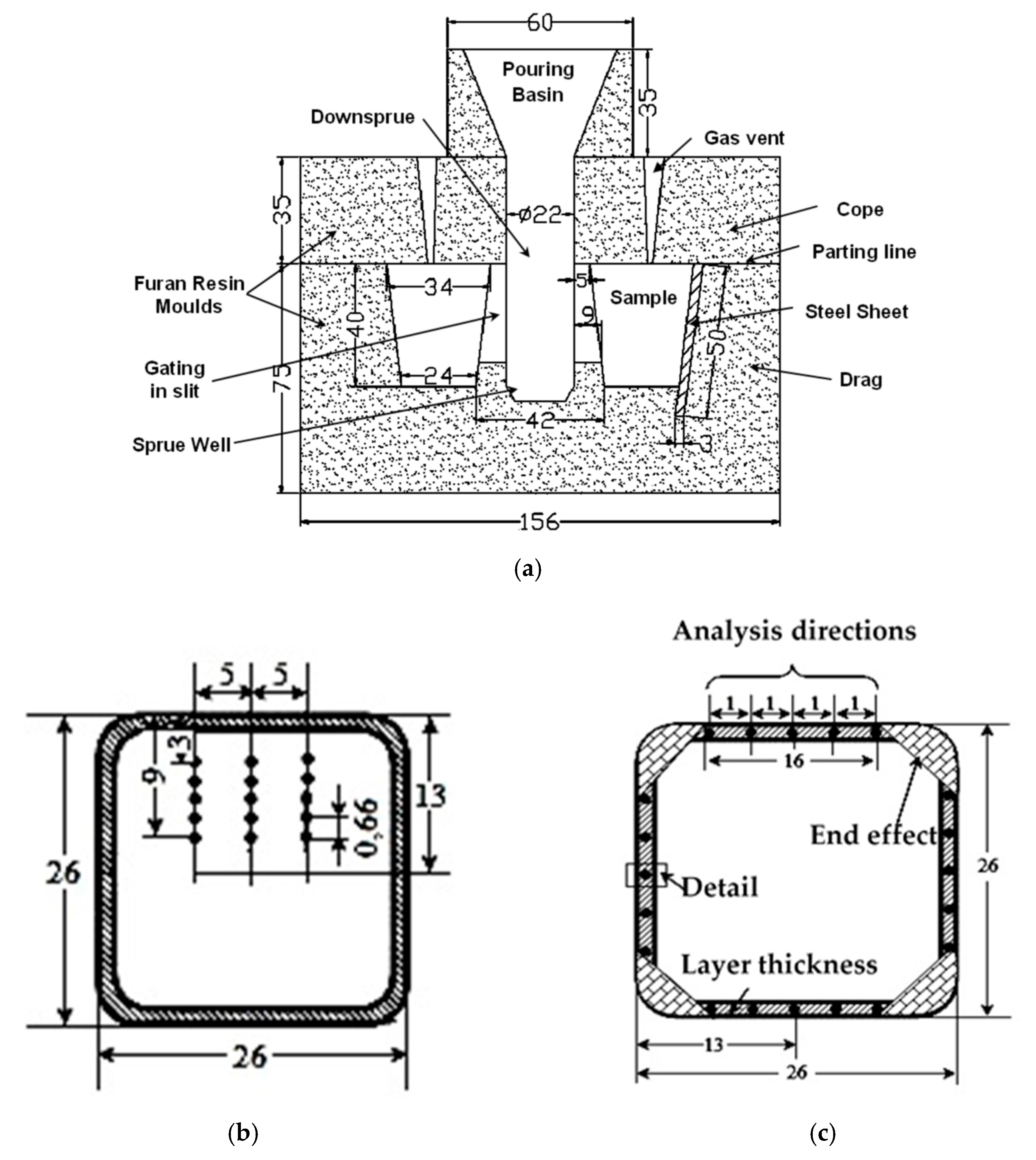
3. Materials and Methods

The experimental heat is melted in an acidic refractory lined, coreless induction furnace (100 kg, 2400 Hz). The base cast iron melt is heated to 1500–1520 °C and then tapped into a 30 kg nodulizing ladle. A Tundish Cover Mg-treatment technique, with tundish cover removable type, is used along with a 2.0 wt.% Mg-bearing FeSi master alloy (Table 1). A pocket is made in the bottom of the ladle, to receive Mg-bearing FeSi, while the liquid base iron is delivered from the tundish through a calibrated hole, in a ladle with 2:1 ratio between height and diameter. This nodulizing technique is selected to reduce smoke and flare, improve Mg-recovery, reduce temperature losses, and obtain a better consistency of final Mg. After Mg-treatment, an inoculation during the transfer of Mg-treated iron into the pouring ladle (0.5 wt.% FeSiCaBaAl alloy addition) is employed.
All the test castings are poured at 1450 °C in furan resin moulds. A furan resin (3.0 wt.%) and P-toluol sulfonic acid (PTSA) (6.53 wt.% S content and 1.5 wt.% addition) bonded silica sand (95.5 wt.%) (FRS-PTSA) moulding system is used. Four pyramid trunk with square section test samples are cast in this mould according to Figure 2a presentation: 34 mm × 22 mm × 40 mm, 6.24 mm cooling modulus, 0.52 kg weight.
One sample is used as a reference, while for the other three samples, on the inner surface of the mould cavity (in the opposite position with the gate), a thin steel sheet is applied, before Mg-treated and inoculated iron melt pouring. Here, 0.5, 1.0, and 3.0 mm steel sheet thickness is used.
Test samples, with and without steel sheet application, are considered for structure analysis, at a section of 26 mm thickness and at 10 mm distance from the top of the pyramid trunk. Un-etched samples are used for graphite characteristics evaluation (nodularity and shape factors) and Nital 2% etched samples for metal matrix analysis (ferrite, pearlite, carbides), respectively.
The structure analysis in the casting body is recorded on the three parallel directions on 3 mm casting thickness, starting at 3 mm distance from the casting surface (Figure 2b). The average value of the 15 analyses is considered. Five analysis points at 0.66 mm distance between them in each direction are used.
Figure 2c shows the procedure of structure analysis on the section of the surface layer. In order to avoid the end (corner) effect, the structure analysis is recorded at a distance of 16 mm, with five analysis points at 1.0 mm distance between them on each side of the pyramid. Surface layer (skin) is defined by graphite degeneration area compared with nodular (spheroidal) morphology. It is measured by metallographic microscope analysis (100:1 magnification) as a visible layer thickness up to prevalent nodular graphite morphology presence, in un-etched (only graphite is visible) (Figure 3a) and Nital etched (also metal matrix is visible) (Figure 3b) conditions [22]. The measurement points of the surface layer thickness are at 100 μm between them, with the average value consideration. Graphite nodularity and representative shape factors variation on the casting section, starting from the casting surface, are also used to evaluate the skin thickness, for each test condition.

4. Results and Discussion

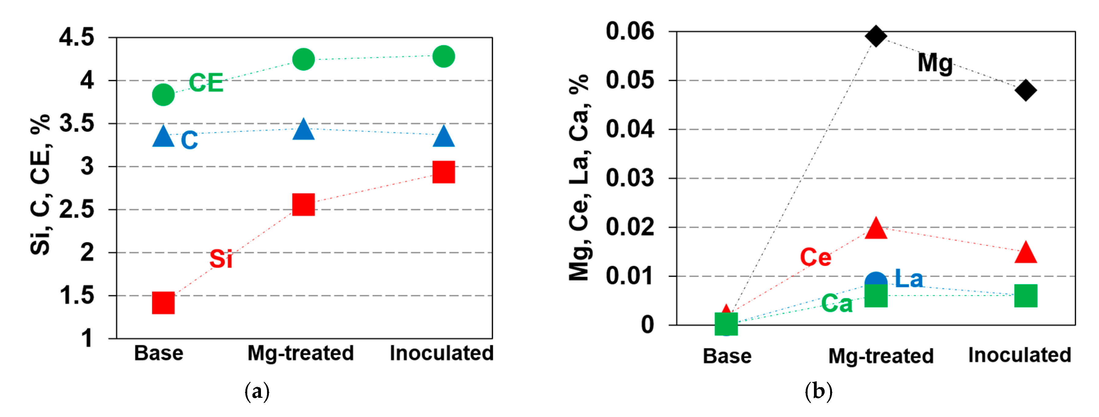
4.1. Chemical Composition

The evolution of the chemical composition from the base iron, tapped from the electric furnace, through Mg-treatment (nodularization), and finally subjected to inoculation, is illustrated by Table 2 and Figure 4. Mg-treatment master alloy has a visible contribution in silicon, an element that is also increased by FeSi based inoculation alloy. As a result, carbon equivalent (CE) also increases up to the final content in iron cast in the test mould.
The active elements, known to contribute to graphite nodularization (spheroidising) process, such as Mg, Ce, La, and Ca, are less than 0.002% in base iron, resulting lamellar graphite morphology. FeSiCaMgRE-treatment alloy has an important contribution in these active elements, which reached the maximum level, specifically for each element.
After Mg-treatment, iron melt will loss a part of nodulizing elements (Mg, Ce, La), as Mg is in the vapour state and other elements in micro-inclusions floating in the liquid iron. Inoculation contributes to restoring the level of Ca.
Double treated cast irons, solidified in the present experimental conditions, are characterized by high graphite nodulizing potential, expressed by a high content of residual nodulizing elements: 0.048% Mgres, 0.015% Ceres, and 0.006% Lares. Al and Ca, as active elements in nodular graphite formation, are also at a normal content in this respect.
Elements with known antinodulizing influence, such as Al, Ti, As, Sn, Sb, Pb, and Bi, are at a lower level, so Thielemann antinodulizing factor (K, Equation (1)) [23] is less than 0.5. According to Thielemann, in magnesium-treated irons, the complex antinodulizing factor K should not exceed 1.0.
As the same elements also have a major effect on pearlite formation (Px, Equation (2)) [23], their low content has a limited contribution to pearlite formation, mainly affected by manganese and silicon contents, resulting in Px less than 1.5, typically for a mixture structure (ferrite and pearlite).
K = 4.4 (%Ti) + 2.0 (%As) + 2.4 (%Sn) + 5.0 (%Sb) + 290 (%Pb) + 370 (%Bi) + 1.6 (%Al)
Px = 3.0 (%Mn) − 2.65 (%Si − 2.0) + 7.75 (%Cu) + 90 (%Sn) + 357 (%Pb) + 333 (%Bi) + 20.1(%As) + 9.6(%Cr) + 71.7(%Sb)
In these conditions, it is expected to obtain a stable, nodular (spheroidal) graphite phase, less affected by detrimental factors. As the major contribution of carbon and silicon of the base iron and silicon contribution of Mg-treatment and inoculation, the final test iron is placed in the eutectic range, as carbon equivalent CE = 4.29%.

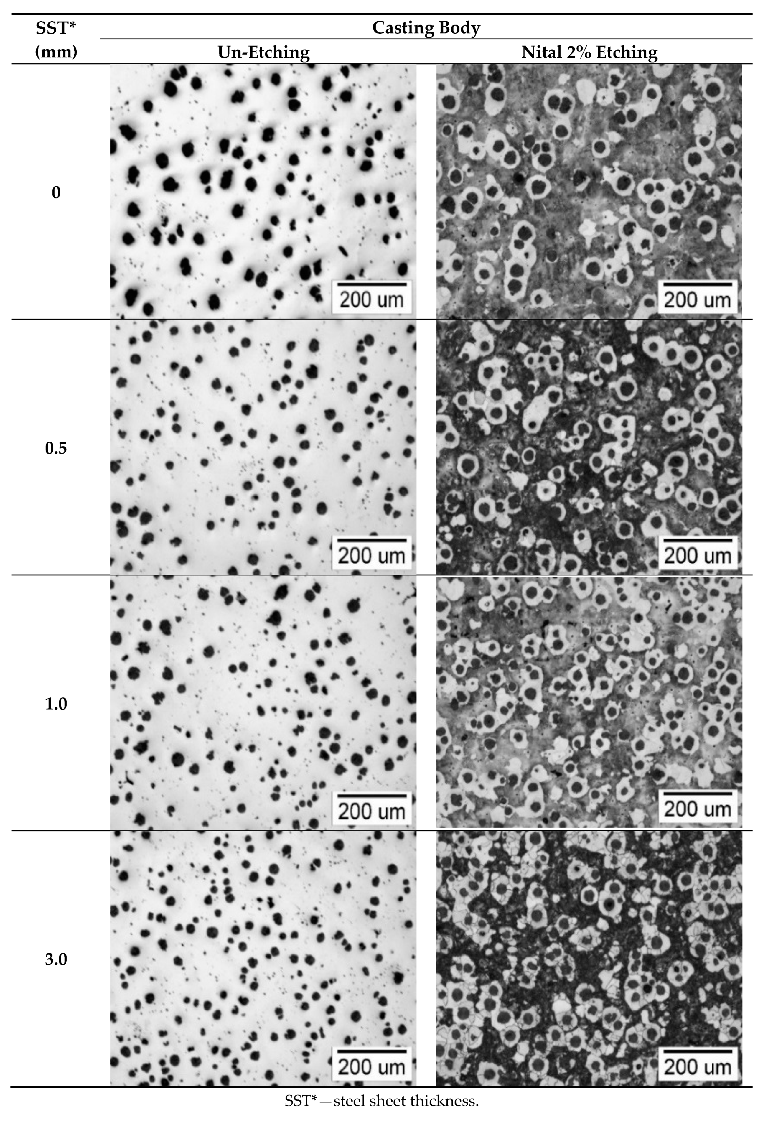
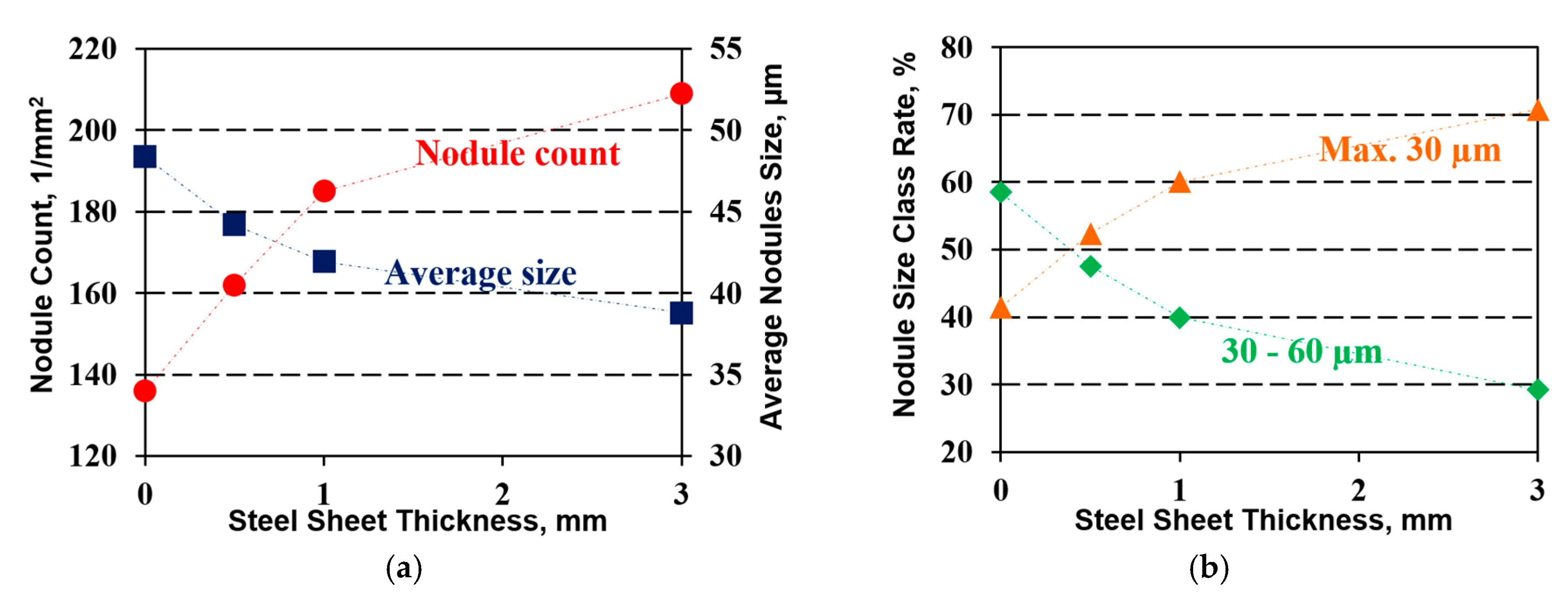
4.2. Structure Characteristics in the Casting Body

Figure 5 shows the typical micro-structures in the casting body (at 1/2 of half section) as graphite (un-etched samples) and metal matrix and graphite (Nital 2% etching), as reference (without steel sheet at the liquid metal–mould interface) and with different steel sheet thicknesses (0.5, 1.0, and 3.0 mm). In all these cases, a typical nodular (spheroidal) graphite morphology is obtained, according to V–VI classes ISO 945.
The presence of the thin steel sheet on the inner face of the mould cavity appears to decrease the nodules’ size and to increase the nodule count, while the compactness degree of graphite nodules is improved. As graphite phase is affected, the metal matrix also makes up changes, resulting a higher amount of ferrite (less pearlite).
The graphite characteristics are evaluated with Automatic Image Analysis (OMNIMET ENTERPRISE and analySIS® FIVE Digital Imaging Solutions software, Lake Bluff, IL, USA). For a graphite nodularity (N), this software uses Equation (3):
N = [(∑ANG+1/2 ∑AIG)/∑Atot]·100 (%)
where
ANG—area of particles classified as nodules (RSF = 0.625–1.0);
AIG—area of particles classified as intermediates (RSF = 0.525–0.625);
Atot—area of all of graphite particles;
RSF—roundness shape factor = 4·A/π·lm2;
A—area of the graphite particle in question;
lm—maximum axis length of the graphite particle in question (maximum distance between two points on the graphite particle perimeter).
As Figure 6 shows, the presence of the thin steel sheet favours the increasing of graphite nodularity (N), roundness shape factor (RSF), and ferrite amount (F). The higher the steel sheet thickness, the higher the level of these structure parameters. These positive effects are clearly up to 1.0 mm sheet thickness; nodularity increases from 81.7% to 86.6%, RSF from 0.618 up to 0.645, and ferrite from 30% up to 45%. A thicker sheet does not affect the roundness shape factor, and limits increased nodularity (up to 81%) and ferrite amount (up to 55%).
The applied steel sheet acts as a chill agent. A higher thermal conductivity of the steel sheet compared with to the mould material will increase the heat extraction, resulting a higher solidification cooling rate, with a beneficial effect on the graphite phase characteristics; that is, nodule count increasing and their size decreasing, at higher fine nodules (maximum 30 μm, Size 7, ISO 945) class incidence. Size 6-ISO 945 (30–60 μm) rate decreases, without the formation of larger nodules (Figure 7).

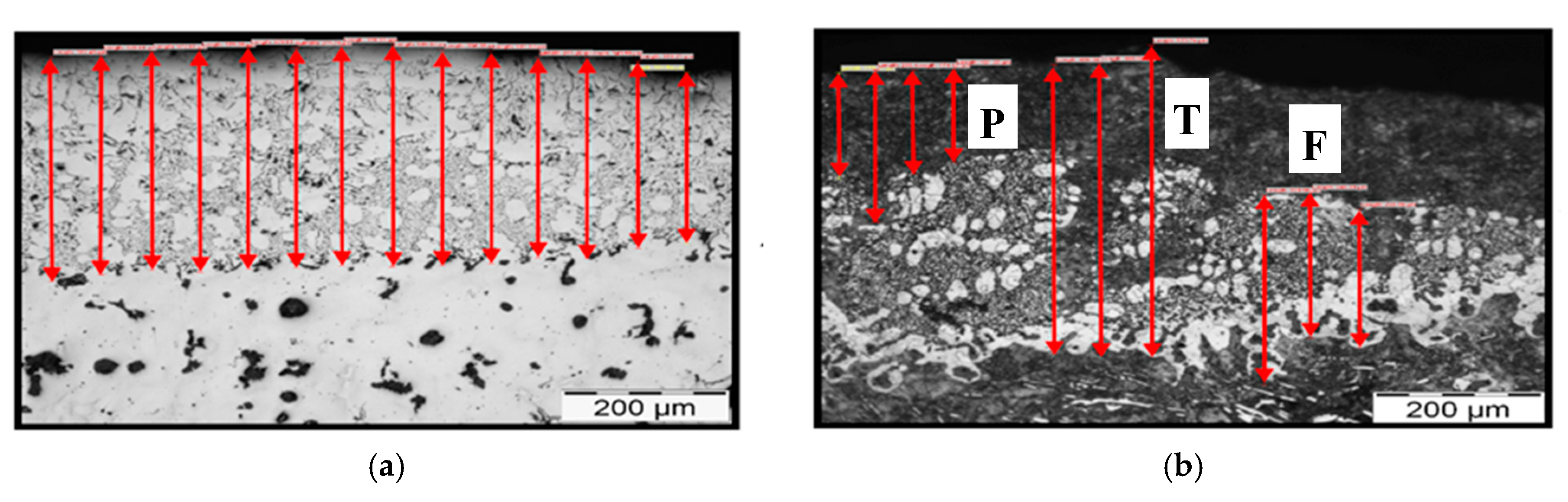
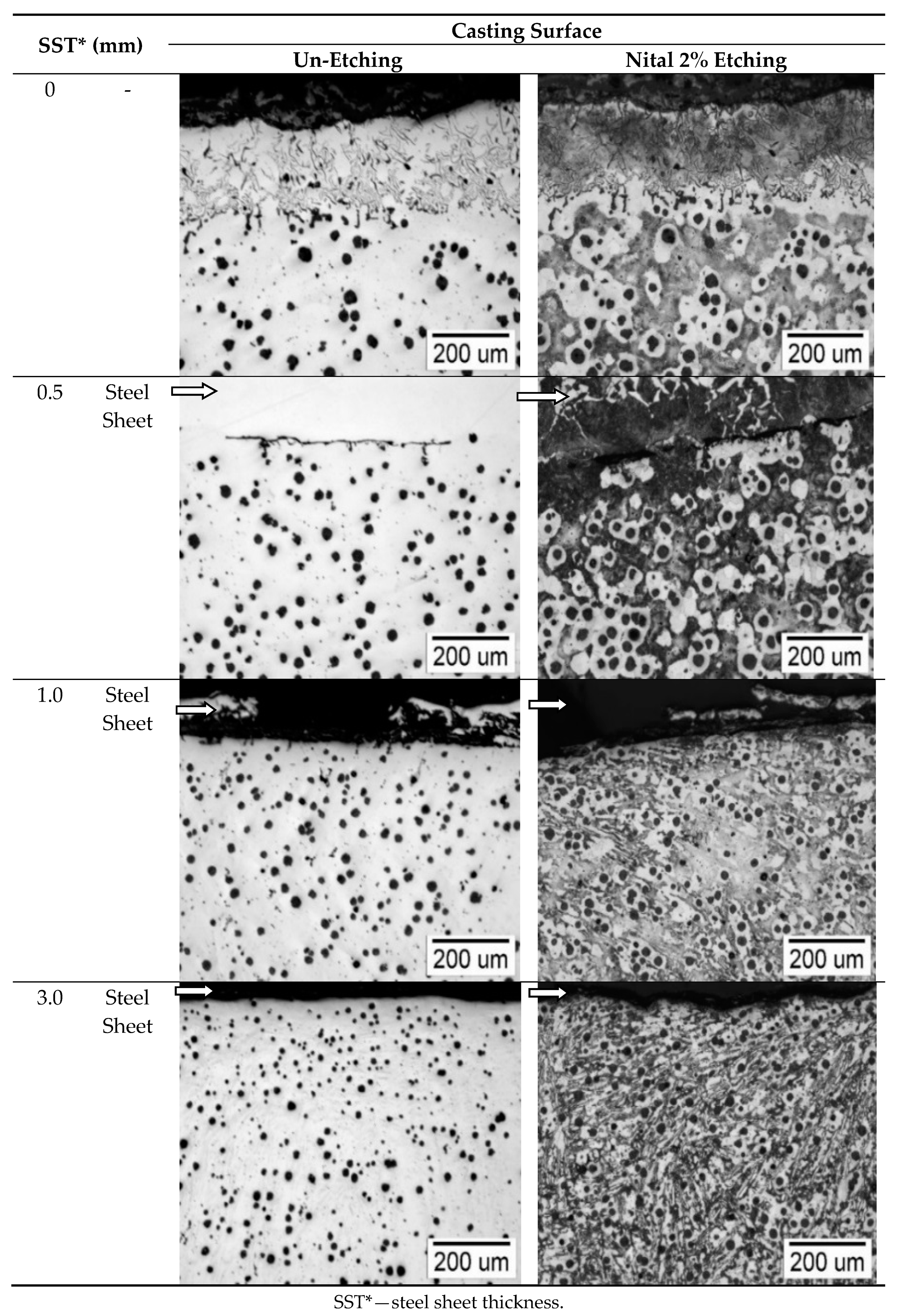
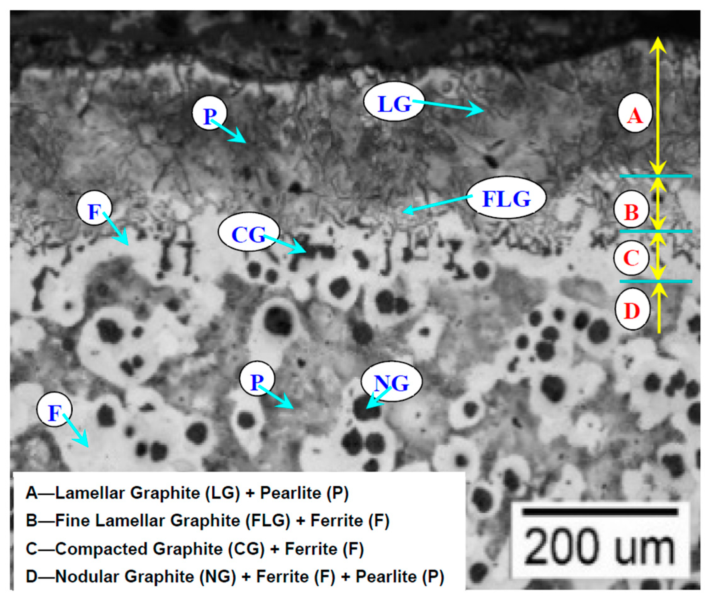
4.3. Structure Characteristics in the Casting Surface Layer

An important structural change is found in the casting surface layer (skin) as an effect of the presence of the thin steel sheet at the metal–mould interface (Figure 8). Figure 9 presents in detail the structure at the surface of Mg-treated iron castings, at the resin mould (including sulphur) and metal interface.
Normal solidification, without steel sheet protection, has a distinct casting surface layer, including complex graphite morphologies:
(a)
lamellar graphite (50–150 m size) and a pearlitic metal matrix at the surface;
(b)
followed by a very fine lamellar graphite (5–40 m size) sub-layer, in a ferritic matrix;
(c)
vermicular/compacted graphite sub-layer, in a ferritic matrix;
(d)
and, finally, a normal nodular (spheroidal) graphite morphology, in a dual metal matrix (ferrite and pearlite) structure, typically for the casting body.
Metal matrix is strongly dependent on the prevalent graphite morphology in the casting surface layer. An outer pearlitic rim associated with type A/E (ASTM) graphite is formed at the casting surface, followed by a ferritic rim associated with fine type graphite (like coral or type D-ASTM), and finally a ferritic rim associated with vermicular/compacted graphite, before the sound body casting base structure, mainly as ferritic-pearlitic with nodular (spheroidal) graphite (Figure 8 and Figure 9). If the graphite degeneration at the casting surface is avoided, nodular graphite in a ferritic–pearlitic matrix characterizes the structure in this area.
Previous works [6,7,8,9,10,11,12,13,14,15,16,17,18,19,20] identified this type of surface degenerated structure as an effect of sulphur diffusion from the mould into the Mg-treated iron melt, consuming the nodulizing elements (Mg, Ce, La), before their action in the graphite spheroidization process. As a result, non-spheroidal graphite morphologies are formed, depending on the remanent content of these elements.
It is expected to record the highest active elements consumption just at the metal–mould interface, resulting in normal lamellar graphite, typical for base iron, untreated to form nodular graphite. As a result of the supposed diffusion of sulphur from the metal–mould interface through the liquid casting body, the graphite degeneration will continue, but step-by-step at a lower level, and the content of diffused sulphur also decreases. From the lowest level at the metal–mould interface (the result of the strong interaction with sulphur delivered by the mould), the final residual Mg, Ce, and La contents increase up to the casting body, unaffected by mould sulphur influence.
Despite the high nodulizing potential of the present experimental cast irons, expressed by the high content of nodulizing elements in final cast iron (0.048% Mgres, 0.015% Ceres, and 0.006% Lares), the generated graphite surface casting layer is present in the complete solidification conditions, at 200–400 μm average level. This is visible in both un-etching (graphite morphology evaluation) and Nital etching (metal matrix consideration) analysis conditions.
The casting skin (degenerated graphite surface layer) is visibly reduced or just avoided on the casting side, which is protected by thin steel sheet. This sheet, interposed between mould, as a possible supplier of sulphur and liquid metal, as receiver of sulphur with possible interaction with nodulizing elements, appears to block S-diffusion. As a result, the mould contribution in graphite degeneration in the surface casting layer is avoided, despite its position as a sulphur supplier.
The chill effect of the steel sheets is also visible in the casting, just below the surface layer, as nodule count increases and their size decreases, especially at thicker sheets (1.0 mm and 3.0 mm). In these cases, the obtained Nital etched samples illustrate the presence of oriented structures, including free carbides in this layer.
In order to evaluate the thickness of the casting surface layer (casting skin), there are considered direct measurement in un-etching and Nital etching conditions (see Figure 3) and graphite phase.
Parameters’ evolution on the casting section. The influence of the steel sheet thickness on the degenerated graphite surface layer (skin) thickness is shown in Figure 10.
An unprotected mould–metal interface leads to the largest measured surface layer thickness, larger in Nital etched analysis conditions (graphite and metal matrix consideration) than in un-etching samples conditions, as only graphite evaluation. Another possibility to evaluate the surface thickness is using the evolution through the casting size of different graphite characteristics (Figure 11).
The presence of the thin steel sheet on the inner mould cavity surface leads to drastically decreasing the thickness of the degenerated graphite surface layer for 0.5 mm thickness sheet, and avoiding it for thicker sheets.
It is supposed that 0.5 mm thickness steel sheet blocked the sulphur diffusion from the mould just after the mould cavity filling. Later, it melted at least partially owing to the heat extraction before casting solidification, allowing a limited sulphur diffusion into the casting surface layer. As a result, the graphite degeneration process was visibly limited, but not totally avoided. Steel sheets at 1.0–3.0 mm thickness did not melt, being a protective barrier to sulphur diffusion from the mould into the iron melt, so no graphite casting skin formed.
Similar results are obtained by the use of graphite shape factors variation, such as roundness shape factor (RSF) (Figure 11b), defined by Equation (3).
As the same mould is used, including four samples, with the same sulphur potential for each one, the maximum detrimental contribution of this element at the metal–mould interface is reached for the unprotected sample. It is supposed that, in this case, the maximum sulphur diffusion into liquid iron is recorded. If sulphur diffusion is blocked in the present experiments by the presence of the thin steel sheet on the metal–mould interface, the mould contribution in casting skin formation is reduced or just avoided.
It is expected that the sulphur diffusion blocking by other ways, such as by dense coatings or coatings with de-oxidation or/and desulphurization capacity, for example, will have a similar beneficial effect. Recently [24], it was found that carbonic material or iron powder supplementary addition to the mould coating decreases the incidence of the casting skin formation, with carbonic material being more efficient as limiting oxygen and iron powder to limit the negative effect of sulphur on the casting skin thickness.
The control of the graphite morphology, especially in heavy ductile iron castings, very sensitive to nodular graphite degeneration, owing to a longer solidification time, is essential especially as a dynamic tensile process evolution [25]. On the other hand, alloying of the ductile cast irons with some elements could improve the castings’ quality, such as tensile properties and hardness, as well as resistance to oxidation and corrosion, but could also affect the graphite phase quality.
It is found that high silicon ductile cast irons are sensitive to lower nodules’ compactness formation, such as type V instead of type VI (ISO 945) graphite, also with a high sensitivity to casting skin formation [17,24].
Aluminium is found as a good replacement of silicon in ductile cast irons, with real benefits such as higher strength and hardness, as well as better wear and oxidation resistance [26,27], but its anti-nodularising effect in Mg-treated cast irons must be considered. A high sensitivity must also be expected to cause graphite degeneration in the casting surface layer. In all of these cases, a supplementary contribution of sulphur, supplied by mould or/and mould coatings, will increase the casting skin formation process, resulting in the benefits of sulphur diffusion blocking into the iron melt, before solidification.

5. Conclusions

A research program is undertaken to explore the possible beneficial effect of sulphur diffusion blocking at the metal–mould interface, on graphite degeneration at in Mg-treated iron castings. On the basis of this work, the following main conclusions can be drawn.
(1)
The world foundry practice shows that rigid mould, furan resin, and P-toluol sulfonic acid (PTSA) bonded silica sand moulding system is attractive for ductile iron castings production, but it is an important supplier of sulphur for iron melt, before its solidification.
(2)
It is confirmed that, without protection, the supposed sulphur diffusion from the mould material through iron melt is an important contributor for graphite degeneration at the surface casting layer.
(3)
In the present experimental solidification, it is found that the free sulphur diffusion could also contribute to this phenomenon inside of the casting body, expressed by decreasing graphite nodularity and graphite compactness degree.
(4)
A higher nodulizing (spheroidising) potential of Mg-treated cast iron, expressed by a high content of known nodulizing elements (0.048% Mgres, 0.015% Ceres, and 0.006% Lares), could decrease the occurrence of surface graphite degeneration, but it is not enough to avoid this phenomenon (200–400 μm skin thickness in the present experiments).
(5)
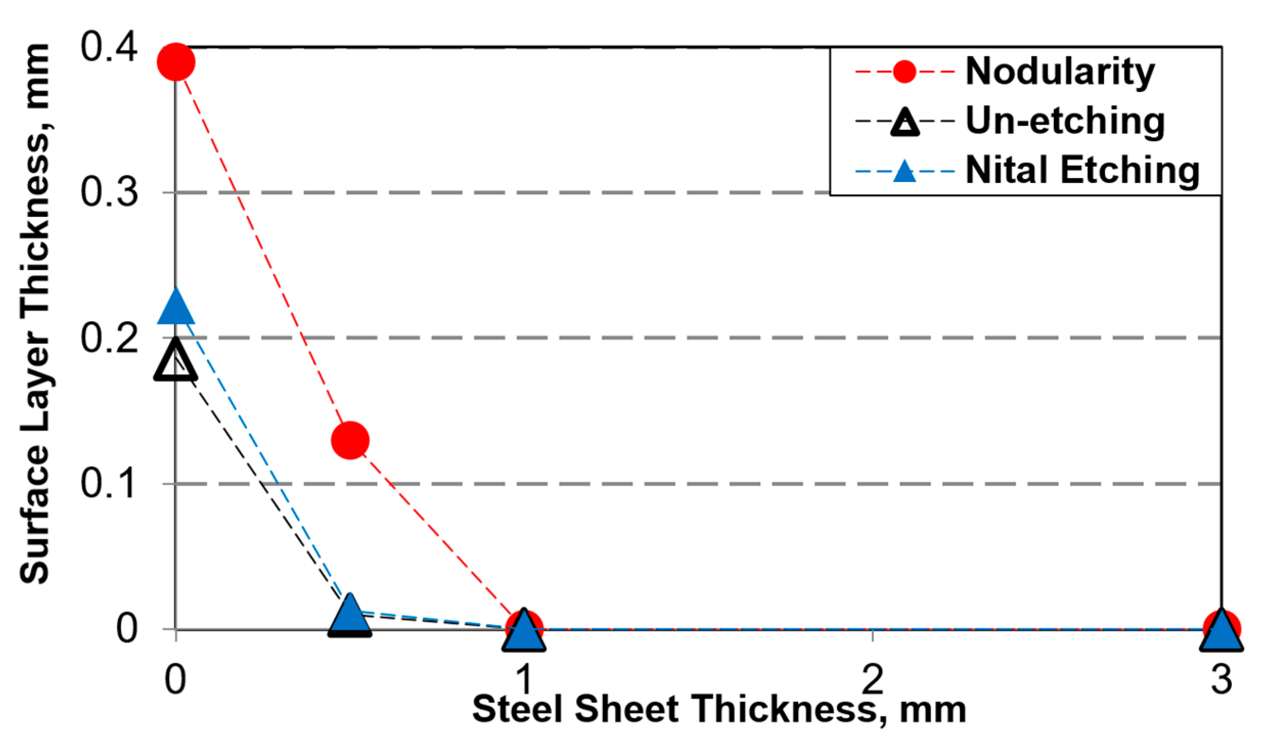
The thickness of the surface graphite degenerated layer appears to have different values, depending on the evaluation technique; that is, it is thicker by measurement in the presence of metal matrix (Nital 2% etching), compared with the only graphite phase consideration (un-etching), with the highest values obtained using graphite parameters, such as nodularity and shape factors’ variation on the casting section.
(6)
In the presence of a thin steel sheet at the metal–mould interface, the thickness of the surface layer decreases or is just avoided. It is supposed that it acts as a barrier, blocking sulphur diffusion into the iron melt.
(7)
If the sulphur contribution of the mould is diminished, such as by blocking its transfer to the iron melt, the graphite degeneration in the casting surface layer could be avoided or, at least, diminished.
(8)
For industrial application, it is recommended to use such barriers on the mould surface, such as dense coatings or coatings with desulphurization capacity.

Author Contributions

D.A., M.C., S.S., I.S., and I.R. contributed equally in conceiving, designing, and performing the experiments; analyzing the data; and writing the paper. All authors have read and agreed to the published version of the manuscript.

Funding

This research was funded by the Operational Programme Human Capital of the Ministry of European Funds through the financial agreement 51668/09.07.2019, SMIS code 124705.

Conflicts of Interest

The authors declare no conflict of interest.

References

  1. A Modern Casting Staff Report. Census of world casting production. Mod. Cast. 2019, 12, 23–25. [Google Scholar]
  2. Heinz-Jürgen Büchner. Forecast 2025 for the Global Foundry Industry. Available online: https://www.foundry-planet.com/fileadmin/redakteur/pdf-dateien/2019_GIFA_Foundry_Industry_2025_v2.pdf (accessed on 1 July 2020).
  3. The European Foundry Industry at a Glance. Available online: https://www.caef.eu/statistics/ (accessed on 1 July 2020).
  4. Dawson, S. Automotive powertrain trends and the market opportunity for cast iron. In Proceedings of the 2nd Carl Loper Cast Iron Symposium, Bilbao, Spain, 30 September–1 October 2019. [Google Scholar]
  5. Gorny, M. Solidification of thin wall ductile iron castings with hypereutectic composition. ISIJ Int. 2010, 50, 847–853. [Google Scholar] [CrossRef]
  6. Boonmee, S.; Stefanescu, D.M. Occurrence and effect of casting skin in compacted graphite iron. Int. J. Cast Met. Res. 2016, 29, 47–54. [Google Scholar] [CrossRef]
  7. Stefanescu, D.M.; Wills, S.; Massone, J.; Duncan, F. Quantification of casting skin in ductile and compacted graphite irons and its effect on tensile properties. Int. J. Met. 2008, 2, 7–28. [Google Scholar] [CrossRef]
  8. Boonmee, S.; Stefanescu, D.M. On the mechanism of casting skin formation in compacted graphite cast iron. In Proceedings of the “Carl Loper” Cast Iron Symposium, Madison, WI, USA, 27–29 May 2009; pp. 138–144. [Google Scholar]
  9. Boonmee, S.; Stefanescu, D.M. Casting skin of compacted graphite cast iron: Part. I evaluation and mechanism of formation and part II influence on tensile mechanical properties. In Proceedings of the 114th AFS Metalcasting Congress, Orlando, FL, USA, 20–23 March 2010; pp. 10-067–10-068. [Google Scholar]
  10. Labrecque, C.; Gagne, M.; Cabanne, P.; Francois, C.; Beret, C.; Hoffmann, F. Comparative study of fatigue endurance limit for 4 and 6 mm thin wall ductile iron castings. Int. J. Met. 2008, 2, 7–17. [Google Scholar] [CrossRef]
  11. Holtzer, M.; Górny, M.; Dańko, R. Microstructure and Properties of Ductile Iron and Compacted Graphite Iron Castings: The Effects of Mold Sand/Metal Interface Phenomena; Springer: Berlin, Germany, 2015. [Google Scholar]
  12. Dańko, R.; Górny, M.; Holtzer, M.; Żymankowska-Kumon, S. Effect of the quality of furan moulding sand on the skin layer of ductile iron castings. ISIJ Int. 2015, 54, 1288–1293. [Google Scholar] [CrossRef] [Green Version]
  13. Ivan, N.; Chisamera, M.; Riposan, I. Influence of magnesium content and coating type on graphite degeneration in surface layer of iron castings in resin sand-PTSA moulds. ISIJ Int. 2012, 52, 1848–1855. [Google Scholar] [CrossRef] [Green Version]
  14. Chisamera, M.; Ivan, N.; Riposan, I.; Stan, S. Iron casting skin management in no-bake mould—Effects of magnesium residual level and mould coating. China Foundry 2015, 12, 222–230. [Google Scholar]
  15. Ivan, N.; Chisamera, M.; Riposan, I.; Stan, S. Control of graphite degeneration in the surface layer of mg-treated iron castings in resin sand—P-toluol sulphonic acid (PTSA) molds. AFS Trans. 2013, 121, 379–390. [Google Scholar]
  16. Stan, S.; Chisamera, M.; Riposan, I.; Neacsu, L.; Cojocaru, A.M.; Stan, I. Integrated system of thermal/dimensional analysis for quality control of metallic melt and ductile iron casting solidification. J. Mater. Eng. Perform. 2018, 27, 5187–5196. [Google Scholar] [CrossRef]
  17. Anca, D.; Chisamera, M.; Stan, S.; Riposan, I. Graphite degeneration in high Si, Mg-treated iron castings: Sulfur and oxygen addition effects. Int. J. Met. 2020, 14, 663–671. [Google Scholar] [CrossRef]
  18. Ivan, N. Research on the Graphite Degeneration Phenomenon in the Superficial Layer of the Iron Castings with Compact Graphite Forms. Ph.D. Thesis, Politehnica University of Bucharest, Bucharest, Romania, July 2011. [Google Scholar]
  19. Ivan, N.; Chisamera, M.; Riposan, I. Mg-bearing coating of resin sand-PTSA moulds to control graphite degeneration in the surface layer of ductile iron castings. Mater. Sci. Technol. 2012, 28, 1246–1253. [Google Scholar] [CrossRef]
  20. Ivan, N.; Chisamera, M.; Riposan, I. Mold coatings to reduce graphite degeneration in the surface layer of ductile iron castings. Int. J. Met. 2012, 6, 61–69. [Google Scholar] [CrossRef]
  21. Xiaogan, H. Nodular iron surface deterioration due to PTSA in resin. AFS Trans. 1992, 100, 9–15. [Google Scholar]
  22. Riposan, I.; Firican, C.; Stan, S. Influence of inoculation on the abnormal surface layer characteristics in high nodularity, pearlitic-ferritic compacted graphite cast iron. In Proceedings of the II International Conference of Casting and Materials Engineering, ICCME 2019, Krakow, Poland, 8 November 2019. (CD-Proceedings). [Google Scholar]
  23. Thielemann, T. Zur Wirkung van Spurenelementen in Gusseisen mit Kugelgraphit. Giessereitechnik 1970, 16, 16–24. [Google Scholar]
  24. Anca, D.; Chisamera, M.; Stan, S.; Stan, I.; Riposan, I. Sulfur and oxygen effects on high-Si ductile iron casting skin formation. Coatings 2020, 10, 618. [Google Scholar] [CrossRef]
  25. Song, L.; Guo, E.; Wang, L.; Liu, D. Effects of silicon on mechanical properties and fracture toughness of heavy-section ductile cast iron. Metals 2015, 5, 150–161. [Google Scholar] [CrossRef] [Green Version]
  26. Shaha, S.K.; Dyuti, S.; Haque, M.M.; Maleque, M.A. Development of a new route for Fe-C-Al cast iron production. J. Appl. Sci. 2010, 10, 1196–1199. [Google Scholar] [CrossRef]
  27. Haque, M.M.; Young, J.M. Production of spheroidal graphite aluminium cast iron and the factors affecting it. J. Mater. Proc. Technol. 1995, 55, 186–192. [Google Scholar] [CrossRef]
Figure 1. General view on the surface casting layer (skin) graphite structure (un-etching) at different Mgres content, in the mould without (a) and with sulphur content (b) and un-coated and FeS2 or MgO bearing coatings.
Coatings 10 00680 g001
Figure 2. Pyramid trunk with square section test sample (a) resin sand mould assembly; (b) structure analysis in the casting body; (c) structure analysis in the casting surface layer. (Unit: mm).
Coatings 10 00680 g002
Figure 3. Measurement of surface layer thickness in un-etched (a) and etched (b) samples (P—pearlitic rim; T—total rim; F—ferritic rim).
Coatings 10 00680 g003
Figure 4. Base composition (a) and active elements (b) evolution in double-treatment process. CE—carbon equivalent.
Coatings 10 00680 g004
Figure 5. Structure in the ductile iron casting body (un-etching and Nital 2% etching) at different thicknesses of the steel sheet (SST) applied on the inner mould surface, before pouring.
Coatings 10 00680 g005
Figure 6. Influence of the steel sheet thickness on the graphite nodularity (N) and graphite roundness shape factor (RSF) (a) and ferrite amount (b) in the casting body (see Figure 2b).
Coatings 10 00680 g006
Figure 7. Influence of the steel sheet thickness on the graphite nodules’ characteristics in the casting body: (a) nodules’ count and average size; (b) nodules size class rate, ISO 945.
Coatings 10 00680 g007
Figure 8. Structure in the ductile iron casting surface layer (un-and Nital 2% etching) at different thicknesses of the steel sheet (SST) applied on the inner mould surface, before pouring.
Coatings 10 00680 g008
Figure 9. Graphite morphologies and metal matrix make-up at the metal–resin sand mould interface.
Coatings 10 00680 g009
Figure 10. Influence of the steel sheet thickness on the degenerated graphite surface layer (skin) thickness.
Coatings 10 00680 g010
Figure 11. Influence of the steel sheet thickness on the graphite nodularity (a) and graphite roundness shape factor (b) at different distances from the casting surface (see Figure 2c).
Coatings 10 00680 g011
Table 1. FeSi-based alloys for nodularization and inoculation (wt.%).
RoleAlloySiCaAlMgBaCeLaFe
NodularizationFeSiCaMgRE43.50.980.476.250.0350.840.56Balanced
InoculationFeSiCaBaAl75.01.01.1-1.0--Balanced
Table 2. Chemical composition of the test cast irons (wt.%) *.
IronCSiMnSMgCeLaCaAlTiCE **
Base3.371.420.540.0210.00050.0021<0.0001<0.00020.0060.0053.83
Mg-treated3.442.560.620.0130.0590.0200.0086>0.0060.0120.0064.24
Inoculated3.372.930.620.0150.0480.0150.006>0.0060.0120.0064.29
* Other elements (wt.%): 0.05–0.08 P, 0.045–0.05 Cr, 0.036–0.037 Ni, 0.04–0.05 Cu, 0.008–0.009 Mo, 0.005–0.006 Co, 0.002–0.003 V, 0.0002–0.0004 Pb, 0004–0.005 Sn, 0.0055–0.006 As, <0.001 Sb, <0.001 Te, 0.0009–0.001 B, 0.0002–0.0005 Zn, 0.008–0.01 N, <0.0005 Bi. ** CE—carbon equivalent (CE = %C + 0.3 (%Si + %P) − 0.03% Mn + 0.4% S).

