1. Introduction
The development of the energy sector, CHP and hydroelectric power plants form the basis for the industrial and innovative development programs of any country, especially in areas with enough water resources [
1,
2]. The implementation of energy-efficient technologies based on highly concentrated energy sources should ensure the development of domestic science and innovative technologies, and increase the competitiveness of energy products.
The prospect of energy industry development is based on the introduction of innovative technologies that increase the efficiency of its infrastructure. For example, there are more than 500 CHP, HPP and other types of plants in the Commonwealth of Independent States (CIS), including more than 50 in Kazakhstan. It has also been planned to build nuclear power plants in several countries in the East, in Asia, and in Europe. At the same time, the share of wear of turbine units of CHP and HPP in the global energy sector is about 65%, while the dynamics of prices for energy resources, repair and maintenance is progressively increasing.
Blade turbines are mainly used as an engine to drive generators in the power industry. During operation, the turbine blades are subjected to intense erosion, as well as mechanical and fatigue wear. Emergency failure of a hydroelectric unit of a CHP or HPP associated with a breakdown of a hydro turbine, warping, breakage, erosion wear of the n-stage blades and fatigue failure [
2] may lead to technogenic disasters and heat and power supply breakdowns in whole regions of countries [
3].
Technical accidents at several HPPs and CHPs have shown an acute shortage of innovative technologies with regard to the repair, restoration and quality control of power units.
To solve this problem, it is necessary to modernize the restoration process and introduce new approaches in the development of innovative methods of surface modification. The analysis of global manufacturers of restoration equipment units, such as Siemens-Sabaros, Plakart and Costolins, has shown that indicators of high quality of restoration can be reached through the application of known physical processes of plasma substances [
4,
5].
The shortage of restoration technologies necessitates the replacement of worn blades with new ones, which results in enormous material costs. For example, the cost of a new 27th-stage blade of the T-100/120-130 turbine is about 950 euros, and a set of blades for one disc costs more than 106,400 €, while the cost of repair of three stages with 112 blades in each is 79,800 €. Thus, the repair of the blades of moderately worn turbines is economically feasible, since it does not exceed 25% of the cost of new ones. Based on the results of timing studies, it has been found that about 10% of new blades received for replacement fail [
4,
5].
The main difficulty in the technological recovery process of turbine blades of CHP is the process of forming the optimal structural-phase state of the metal, eliminating the occurrence of cold-drawn cracks and providing vibration resistance to dynamic loads [
6,
7,
8]. At present, significant results have been achieved in studies of plasma recovery of turbine blades of CHP [
9,
10,
11,
12,
13,
14].
When repairing turbine blades according to the traditional method [
10,
11], a plate shall be welded to the place of the worn section of the edge. The disadvantage of this method of repair is the complexity of manufacturing and welding the plate, as well as the high level of tensile residual stresses arising after welding the plate and protective pads.
Previously, the researchers Godovskaya, G.V., Isanberdin, A.N., Jablonski, F. and Kienzler, R. developed a turbine blade recovery method [
11,
12] that included removal of damaged material, weld overlay of the recovered area, heat treatment to remove residual stresses, and mechanical treatment of the blade.
The disadvantage of the method is the use of heterogeneous materials for weld overlaying (alloys of nickel with iron and cobalt with iron, as well as alloys of nickel, cobalt, and iron), which on the one hand provides a combination of the plasticity (δ
5 = 15%) of the weld deposit and the high hardness (78–89 HRC) of its surface, while at the same time leading to the formation of a heterophase layered structure, which reduces corrosion resistance [
10].
A method for recovering the working blades of steam turbines proposed by Lappa, V.A., Fedin, I.V., Khromchenko, F.A., Stratfull, R.F. and Spellman, D.L. [
13,
14,
15,
16] included the removal of blades from the rotor, removal of protective pads, mechanical removal of the damaged edge section, multilayer surfacing of the restored edge section, furnace heat treatment, mechanical treatment of the blade and welding-on of stellite protective plates. A significant disadvantage of this method is the lack of heat treatment after welding of the protective pads, as a result of which the blade material retains the high heterogeneity of the structural-phase composition and a high level of tensile residual stresses.
The researchers Gonserovskiy, F.G., Bi, G., Gasser, A., Wangyao, P. and Lothongkum, G. were also not able to reduce the residual stresses and high heterogeneity of the structural-phase composition of the material of the restored blade during overlaying and welding in the zone of thermal influence [
17,
18,
19]. Tensile residual stresses reduce the fatigue resistance of the material, and the structural-phase heterogeneity of the material reduces its corrosion resistance.
Thus, there are scientific gaps in the study of the influence of structural changes in the blade feather material on the formation of fatigue defects [
9,
16,
20]. Therefore, it is an important scientific and technical task to develop an innovative recovery technology that can improve the physical and mechanical properties and provide optimal structural and phase composition of CHP and HPP turbine blades.
The scientific problem is that it is necessary to establish the relationship between the modes of the technological process of recovery and the optimal physical and mechanical properties of the resulting coating (adhesion, hardness, material strength, coefficient of thermal expansion).
Thus, the purpose of the study is to increase the resource durability of the turbine by developing an innovative technological process of plasma phase restoration of (substandard) blade structure.
2. Materials and Methods
Currently, the Commonwealth of Independent States (CIS) countries typically use plasma technology for power equipment recovery using plasmotrons, multicomponent powders, and wires [
10,
11,
18,
19,
20].
Strict reliability requirements for gas turbine blades regulate heat-resistant and heat-proof nickel and cobalt alloys such as Kh25N13, 12Kh18N9T, Kh18N10T, 15Kh17N12V3F, etc. [
21,
22]. The structure of an alloy consists of a
Y-matrix and a relatively evenly distributed reinforcing fine g
/-phase. As a result of long-term operation at high temperatures, various kinds of defects (cracks, potholes, erosion, etc.) appear on the surface of the blades. In addition, the alloy undergoes structural transformations, which are expressed, as a rule, in the coagulation and morphology of the strengthening Y
/-phase and carbides in the body and along the grain boundaries.
Therefore, the high physical and mechanical properties of the surface to be restored depend not only on the material of the restored element but also on the modes of the technological process of restoration. Due to the physical characteristics of the coating formation process, internal stresses increase in the layer with increasing thickness, in turn impeding the process of adhesion with the underlying surface. The low ductility of self-fluxing alloys and the high coefficient of linear expansion create a risk of cracking of the coating during cooling. Therefore, it is necessary to carefully choose the recovery and thermal processing modes [
18].
To substantiate the optimal modes of CHP turbine blade plasma recovery, a multifactor experimental method was applied, wherein y
1, as the hardness of the sputtered layer, y
2, as the tension, and y
3−, as the adhesion, characterizing the strength and depth of adhesion, were accepted as criteria for the optimization of plasma sputtering. Ten factors were selected before constructing the experimental matrix: x
1, x
2, x
3, x
4...x
10, each varying at two levels (max) and (min) (
Table 1). In the expanded form, the matrix for the sputtering experiments is represented by ten main factors (
Table 2).
The experiment matrix was implemented using MathWorks software Matlab R2019b B9.7.0.1261785. After the construction of the matrix, its applicability was checked. A matrix is useful if there are no two columns that are of the same type. After the implementation of the experiments, their results were written out. The test was carried out for one criterion (only for the spraying distance—x
10), with a polynomial model built for it, which describes the dependence of y on this criterion as well as possible. In addition, these values of the x
10 criterion and y were applied to a general, already linear model. The equation for y
1 (hardness) against x
10 (spraying distance) is as follows:
The limits of variation of sputtering modes were determined by the classical method when any parameter was changed, with all others remaining constant.
Two variants were used as powder additives when spraying the surface to be restored.
The first was a self-fluxing powder B. 03 PR-M73Kh6C3R3 (HRC-47-52), NiCг-Fe + 50 (80) %Cr3C2 based on nickel. The second one was 74Kh16C3R2 (Innovative Patent No. 21589 “Plasma Coating of Metals”).
Research into the hardness of the sprayed elements was performed at Petropavlovsk RMZ JSC, “Remplazma” LLP. Observation of the repaired stock showed low hardness of the coating and heterogeneity of the layer with the application of PN68Kh21C5R powder. To increase the hardness of the sputtered layer, its adhesion, and the possible reduction of the number of pores and cracks, it was decided to introduce a special powder composition MC4Cr16SiVMn into the plasma jet. Chromium (Cr) was added to the powder in order to increase the coating hardness and adhesion strength. Nickel (Ni) was added to the powder in order to ensure corrosion resistance. The experiments used powders with a particle size from 50 to 100 µm.
Thus, according to the results of the multifactorial experiment, it was established that one of the main indicators of the restoration quality was the structural-phase state of the boundary layers and the base of the element. The mechanism of formation of the dispersed medium of the structure under the thermodynamic influence of plasma was investigated for its effective modification. Additionally, the following connections were established on the basis of the regression equations:
- (a)
Between the hardness of the coating to be sprayed and its determining factors;
- (b)
Between tension and its determining factors;
- (c)
Between the adhesion of the sprayed layer and its determining factors.
By applying them in reducing production, it becomes possible to choose the optimal modes of spraying and the effective limits to their variation.
The reliability of the results of the study was determined based on the application of non-destructive testing methods (metal magnetic memory method) and metallographic studies with subsequent construction of diffractograms of the heterogeneous material structure [
23,
24]. In the course of the study, the measuring instrument IKN-7M-16 was used, with a relative error of the measured magnetic field for each measurement channel of not more than ± 5% and a relative error of the measured length not more than ±5% [
25].
A systematic approach to the study of the mechanism of material stress state formation at different coefficients of thermal expansion made it possible to establish its key processes. In detonation sputtering, the kinetics and mechanism of coating formation are determined by the plastic deformation of the powder particles and the underlying surface in the collision zone, where there was a local increase in the activity of the solid underlying surface under the pressure of the impacts of solid particles causing elastic lattice distortions and plastic deformation. This leads to an increase in the adhesion strength of the coating to the base metal. To improve the physical and mechanical properties of the sputtered layer and improve the adhesion to the underlying surface, an additional reflow operation was used. When a particle, heated to a liquid or plastic state, hits the prepared underlying surface, its deformation, spreading, cooling and crystallization occur, while the particle is fixed to the surface microroughness only mechanically. If the underlying surface–coating pair has a chemical interaction or fusion, the adhesion force of the coating to the underlying surface also increases. The whole mechanism of the process—from heating the particle in the plasma jet to cooling it on the underlying surface—occurs during 10−3–10−4 s. The crystallization time is 10−5–10−7 s.
At such rates of crystallization, large stresses appear in the coating (typical for all types of thermal spraying), the value of which depends primarily on the coefficient of thermal expansion (CTE) and the temperature of the underlying surface and coating materials. As the coating thickness increases, thermal stresses also increase. In some cases, stresses can cause peeling and tearing of the coating. Therefore, when spraying, it is not recommended to allow heating of the underlying surface to a temperature above 300 °C.
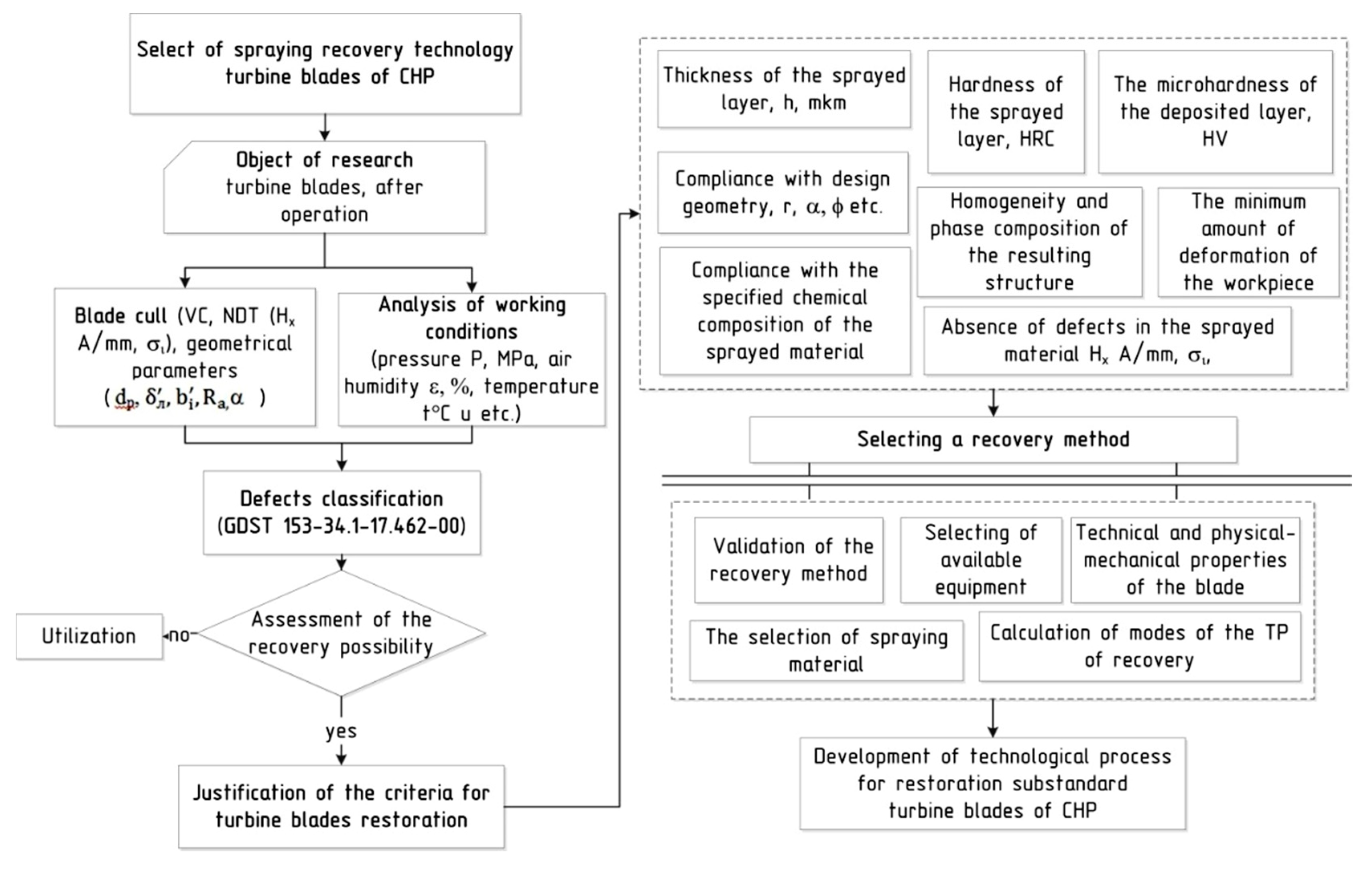
Production experience and the main results of the study on the renovation of blades allowed for development of a structured model of a reasonable choice of technology for the recovery of substandard CHP turbine blades by spraying (
Figure 1) [
23,
24,
25,
26].
The effective implementation of this algorithm involves the following sequence of actions.
- Step 1
The choice of the object of research—CHP turbine blades after a certain period of operation.
- Step 2
Analysis of operating conditions of the blades, diagnostic of the defects.
- Step 3
Classification of the identified defects according to the requirements of regulatory documents. Assessment of the possibility of recovery (terms of the regulatory documents, Н
x, σ
−1, ΣF
tot, R
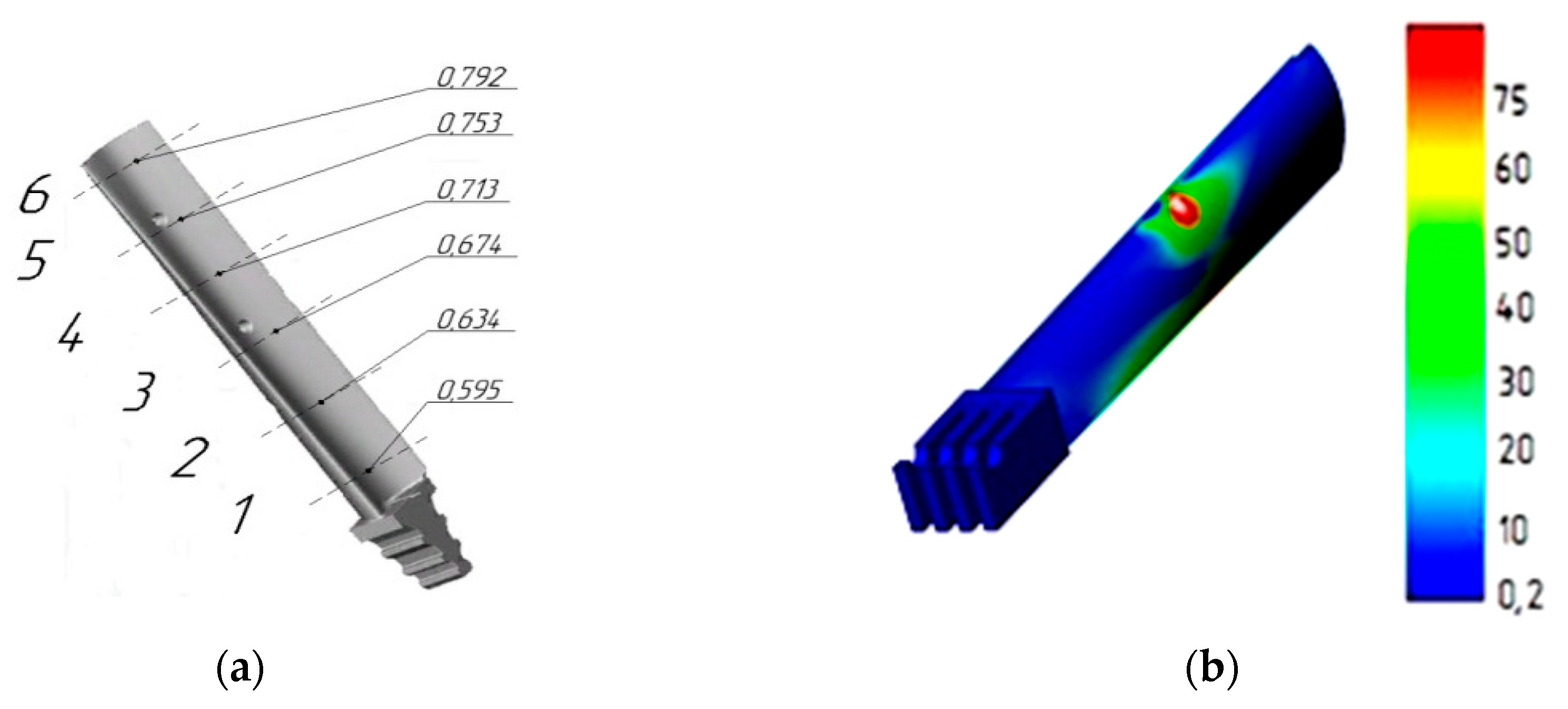
a, HV, HRC). The detection of blade defects that have passed their cycle of operation was carried out using the developed integrated assessment method [
25] and the requirements of regulatory documents [
22,
27]. According to the conducted studies and the results of computer modeling in the SolidWorks environment [
26], the main load б falls on the 4, 5 and 6 sections of the blade,
Figure 2a,b.
With increasing leverage load, tensile or compressive stresses increases. Transient modes of operation for a short period of time also significantly increase the load, which ultimately leads to a significant increase in internal bending stresses, displacements, and deformations of the blade metal, as well as to its fracture.
The studied mechanism of formation of internal stresses became the basis for the development of innovative technology of the recovery of CHP turbine blades of by the method of “prosthetics” under the following conditions:
where
is the critical length of the feather from the tail end of the blade required for recovery, m;
is the coefficient of applicability for recovery;
is the critical height of the tail part of the blade feather, .
L is the length of the blade feather, m.
Previously, blades with similar damage were believed to have been scrap.
- Step 4
In the case of a positive decision on the recovery of off-grade CHP turbine blades, the choice of criteria for the surface to be restored by spraying.
- Step 5
Based on the selected criteria, determination of technological process parameters (equipment, powder material, selection of the technological process scheme).
- Step 6
Development of the technological process of recovery.
The structural scheme of the algorithm, taking into account the quality criteria of recovery of substandard blades allowed for development of an innovative technological process of recovery.
3. Results
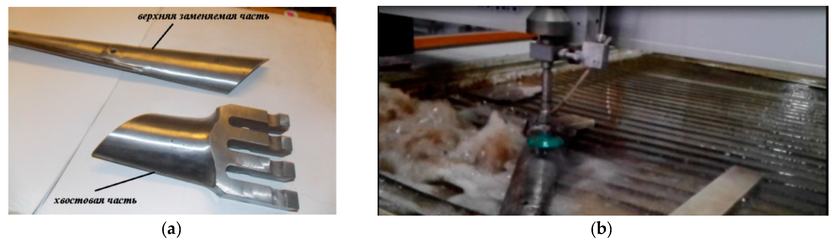
Taking into account the results of experimental studies at “Remplazma” LLP, experimental works were carried out on the recovery of blades with unacceptable defects that needed to be repaired, corresponding to condition (1). Recovery of the blades is proposed to be carried out by the method of “Prosthetics”. The essence of the method is as follows. Initially, mechanical treatment is carried out until erosive and corrosive wear is completely removed. Next, the worn part of the blade is removed, then being replaced by a newly manufactured implant element (
Figure 3a). During the experiment, it was determined that the removal of the off-grade part of the blade by the mechanical or thermal method was impractical, because the edge after processing has a tendency to increase in hardness (HRC) by up to 10% or more compared to the hardness (HRC) of the base metal. In addition, metal heats up in the processing zone, which negatively affects the weldability during the repair.
In this regard, the removal of the off-grade part of the blade was performed by waterjet cutting by means of APW 1525BA equipment (Water Jet). Pressure,
P = 400 MPa, cutting speed was 50 mm/min, nozzle diameter d = 1 mm. Suspension speed v
s = 1000 m/s, power of the plant, W = 37 KW (
Figure 3b).
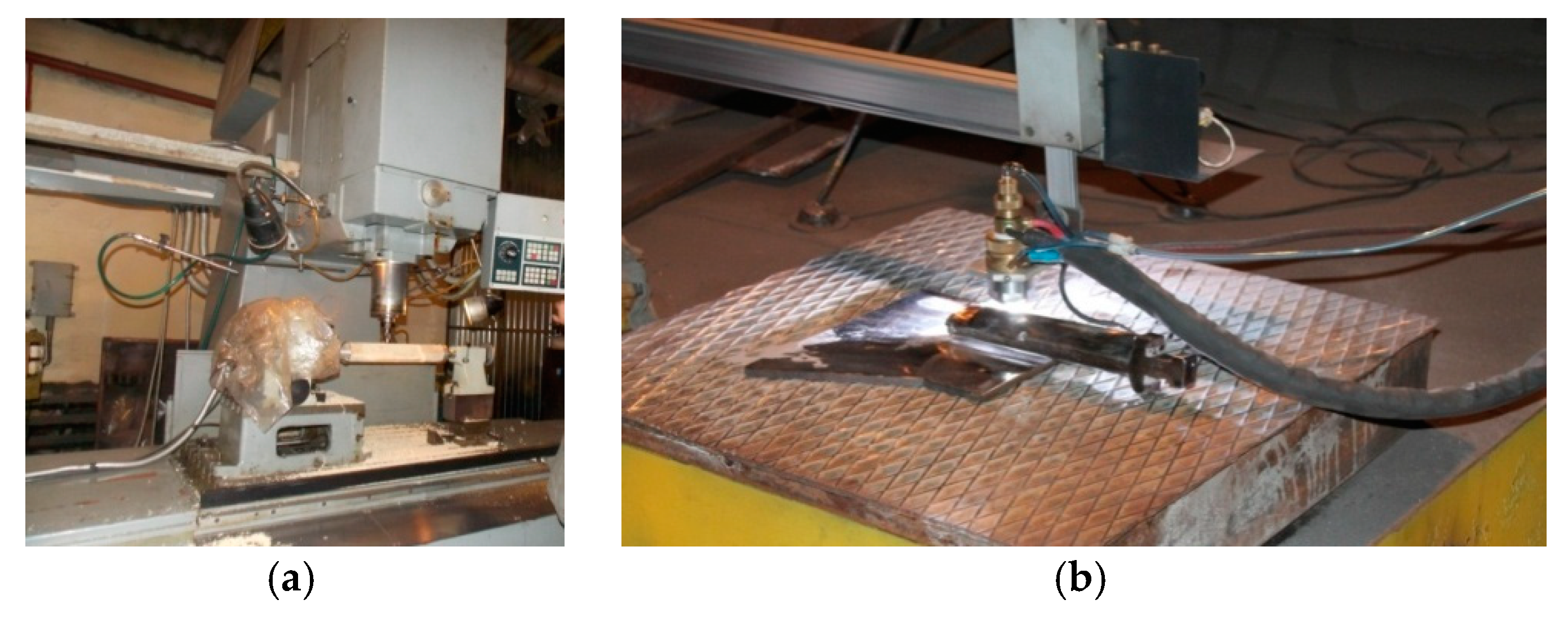
On the edge of the 15Kh11MF steel blade, T-100/120-130 turbine, metal hardness after cutting was 240–250 according to the Brinell scale and was in the same range as the base metal. The manufacture of the blade prosthesis was also carried out by cutting it from the previously operated standard blade and by manufacturing a new one by an upgraded 2E450 CNC machine (
Figure 4a). After manufacturing the missing part of the implant blade and fitting its design geometry to the tail part, docking and welding, as well as edge hardening, were performed according to the scheme shown in
Figure 4b.
After the joining of the two structural elements “feather–tail part”, microplasma welding was carried out using experimentally grounded modes in which the linear energy did not exceed 20 cal/cm. the value of the linear energy Q was approximately determined by the formula Q = (125–150) τ Cal/cm, where τ is the cross-sectional area of the seam.
After the welding of the blade elements, the isothermal release of the blade was carried out. Residual stresses were determined by a method based on the magnetic memory of the metal [
23]. Equalization of the stress state was carried out by thermal cycling. The blades made of 15X11MФ steel were first heated to the temperature of 680 ± 20 °C. The technological exposure was calculated at a rate of 3–5 min per 1 mm of blade thickness. Then the blades were gradually chilled down to a temperature of 50 °C above the temperature of the second type of embrittlement. Then the blades were heated up to 660 ± 20 °C and exposed i times on a cyclical basis. In total, 4–5 cycles were performed, with the possibility to reduce residual stresses to a minimum value. For high-quality adhesion of the coating to the base of the part, the surface roughness for plasma spraying should be 10–60 Rz; meaning the surface should be matte. Then, the weld overlay was carried out on a pre-prepared surface, while the weld overlay process was also accompanied by a sequential cycle of electric arc treatment. The built-up surface and the zone of thermal influence were subjected to ultrasonic impact treatment with the multiplicity of the thermal impact zone treatment set equal to (n + 1), where n is the multiplicity of treatment of the deposited metal. In addition, the working edges were machined and etched after ultrasonic impact treatment, the surface was implanted with nickel-based alloys, and the protective layer was sprayed with concomitant reflow, after which the working edges were thermocycled to ensure residual stresses below the threshold value. Reasonable thermal cycling modes make it possible to model the phase composition of the blade microstructure made of austenitic and martensitic materials.
Restoration of the worn edge by increasing it with layer surfacing and plates welding. In both cases, the restored working surface of the blade edge with the implant was strengthened by applying a protective layer (1) and subsequent stabilization of the structure by thermal cycling. The linear energy during electric arc processing was set basing on the condition that gn = (75–100) h, where h is the thickness of the metal in the processing zone (2). When carrying out weld overlaying, the linear energy was set from the condition obtained empirically:
where
F is the cross-sectional area of the bead weld of the applied seam.
After weld overlaying and electric arc treatment of the deposited metal, the repair zone was subjected to ultrasonic impact treatment (UIT). The number of treatments of the thermal impact zone was set to one more than the number of deposited layers, i.e., the multiplicity (n + 1) was provided, where n is the number of treatments of the deposited metal. Then the spraying of the protective layer with the concomitant reflowing was carried out. Self-fluxing cobalt-containing powders of small fractions were used as a coating. The thickness of the coating was 0.1–0.3 of the thickness of the deposited layer. The coating was subjected to concomitant reflow by the plasma jet. After the application and melting of the coating, the recovery zone was subjected to thermal cycling to reduce residual stresses. This provided preliminary stabilization of the metal structure.
Since the deposited metal from high-chromium steels, especially in the transition zone, increased hardness and brittleness, it is advisable to temper the deposited metal. However, a ferrite layer is formed in the transition zone during the tempering process from the deposited metal to the base metal. This occurs as a result of forced carbon diffusing. On the one hand, the border zone becomes carbon-depleted, and on the other, carbon-enriched. The enrichment of the deposited metal with carbon in the border zone is the main reason for the increased fragility and low resistance to dynamic and vibrational loads. The thermal cycling of the transition zone was performed to eliminate this disadvantage. After the last heating, air cooling to room temperature was performed. As a result, there is an intense α ↔ γ phase transformation, which leads to a rapid decay of ledeburite eutectics and nonuniaxial structures of the lining. As a consequence, the hardness decreases. At the final stage, the deposited metal and the transition zone were monitored for the absence of unacceptable residual stresses using the developed integrated technique. After a comprehensive inspection of the quality of repair, the blades were selectively subjected to fatigue and frequency tests.
At the end of the technological process, the geometric parameters of the blade were brought into line with the technical requirements of the drawing and subjected to vibration tests.
The proposed recovery technology makes it possible to increase the strength characteristics of turbine blades by 10–15%. After working out of technological methods and modes on prototypes according to this scheme, works on the recovery of full-scale blades from two turbines were carried out. The blades were in operation for not less than 10,000 m/h.
4. Discussion
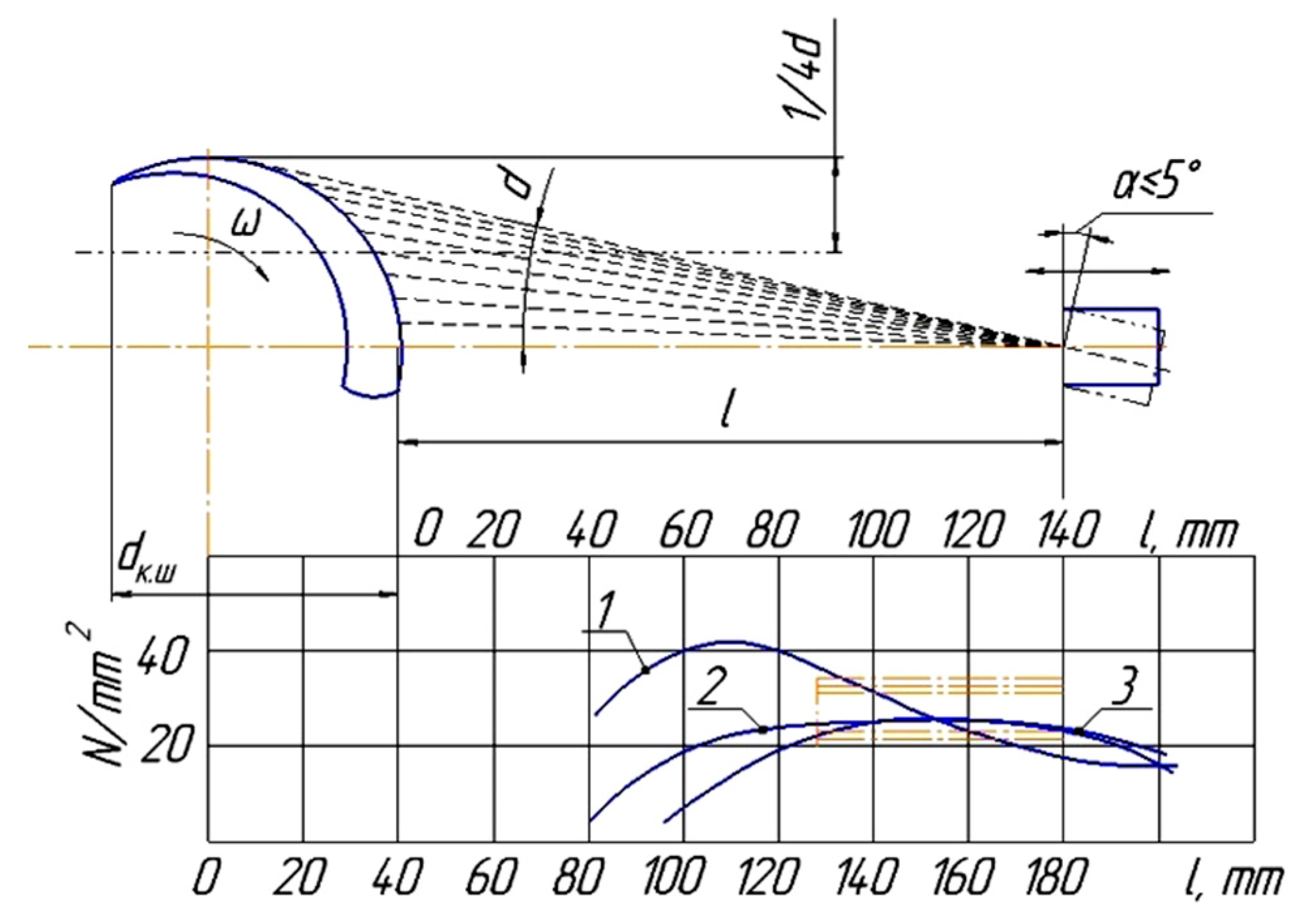
In the course of the experiment at “Remplazma” LLP, it was found that the main parameters of the plasmotron are the distance of spraying
l, particle velocity
v, and granulometric composition by changing which it is possible to increase the utilization rate of the powder, adhesion strength and hardness of the coating. Justification of the main qualitative parameters of technological modes is shown in
Figure 5 and
Figure 6.
Analyzing the graphs in
Figure 5, it was found that too large a distance to the restored part does not provide a strong bond with the sprayed surface. As a result, the particles cool down and do not reach the surface of the element. The small distance between the plasmotron and the blade leads to the spattering of the sprayed material. To increase the adhesion of the sprayed material, it is recommended to ensure the optimal speed of the sprayed particles [
26]. This is proposed on the basis of the following relation:
where
K1 is the coefficient that takes into account the preparation of the surface before coating;
γ is the specific gravity of the applied material, N/m3;
HB is the hardness of the sprayed surface;
υ is the velocity of sprayed particles from the moment of hitting the underlying surface, m/s;
ko is the coefficient of powder utilization;
R is the coefficient numerically equal to the value of microroughness;
σb is the strength of the base metal in the sputtered state, N/m2.
Studies have proved that the influence of the shape and size of particles on the speed of their motion is described by the following equation:
where
υ is the particle velocity, m/s;
υc is the gas jet velocity, m/s;
γс is the specific gravity of gas, kg/m3;
γ is the specific gravity of the material, kg/m3;
Cx is the head drag coefficient;
D is the particle diameter, m.
According to the calculations, it is established that the optimal distance
l is 80–120 mm (
Figure 5), but depending on the technical characteristics of the restored object, it can be increased [
26,
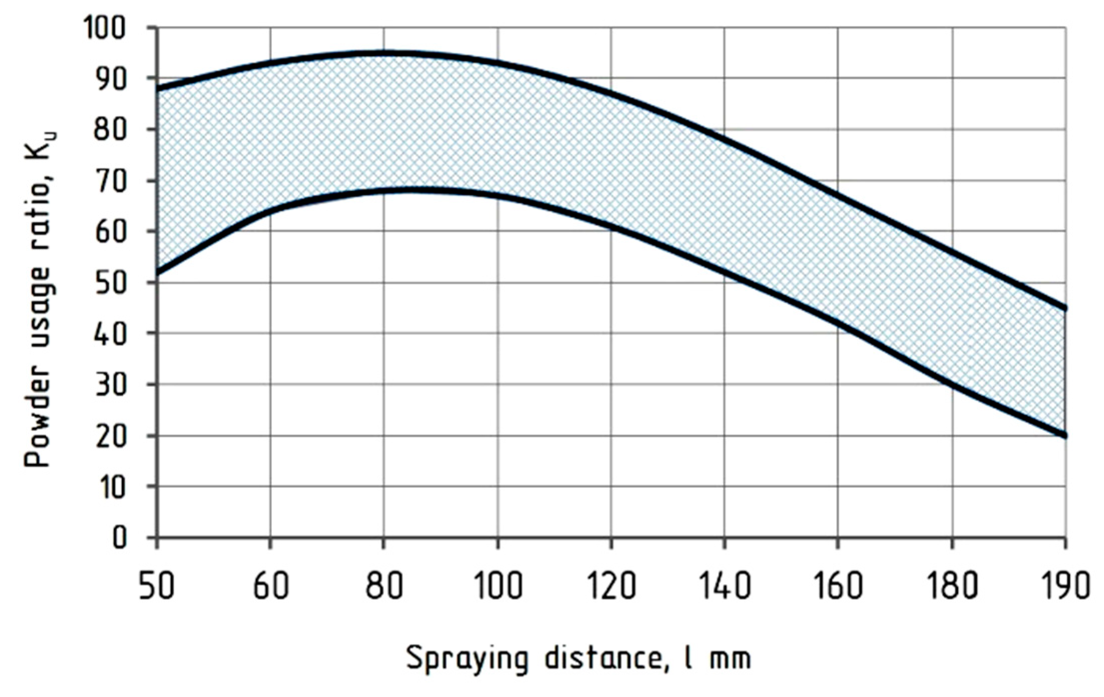
28]. It was also experimentally established that the spraying distance ensures the efficiency of the powder composition with the lowest losses,
Figure 6.
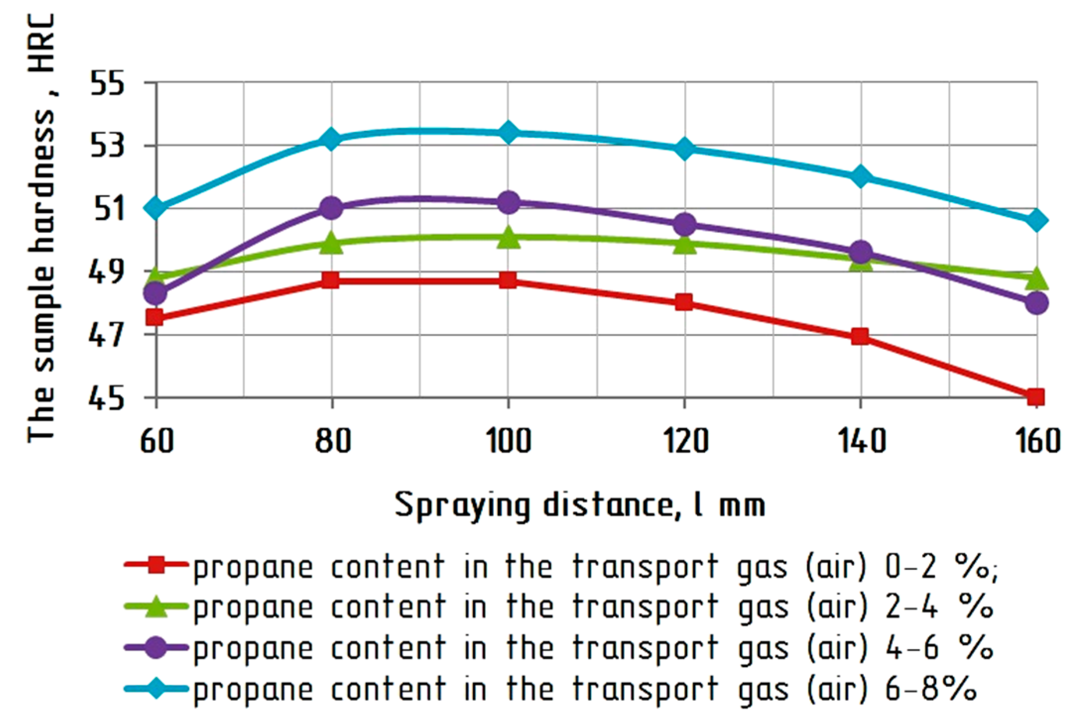
Studies have found that the highest values of the hardness of the sputtered layer were achieved by adding propane as a carrier gas (CG). Following the practical results, the porosity of the coating decreases with an increase in the amount of propane. At the same time, a high concentration of propane in the CG composition leads to cracks on the surface of the resulting coating. In this regard, the propane flow rate Q must be strictly calculated for each brand of material when restoring the working CHP turbine blades (
Figure 7). However, due to the physical characteristics of the process of coating formation, the internal stresses in the coating increase with its increasing thickness, therefore disrupting the process of adhesion of the applied coating to the underlying (or base) surface.
Figure 7 shows graphs of the changes in the coating hardness depending on the spraying distance and the percentage of propane in the carrier gas. Hence, it can be seen that the maximum hardness values of about 51–54 HRC correspond to 6 to 8% of propane in the air at a spraying distance of 80 to 118 mm, which is consistent with previous experimental studies and justifies the optimal technological modes of recovery.
The test for the adequacy of the justification of qualitative parameters was conducted for one criterion (only for the spattering distance—x
10), and a polynomial model was built for it describing the dependence of
y on this criterion as accurately as possible. Then, these values of the criterion x
10 and
y were applied to a general, already linear model. The equation for y
1 (hardness) against x
10 (spraying distance) is as follows:
Similarly, the relationship between y
2 and y
3 is established on the basis of the formative factors x
1–x
10. The equation for y
2 (tension) against x
10 (spraying distance) is as follows:
The equation for y
3 (adhesion) against x
10 (spraying distance) is as follows:
Analysis of the results showed that hardness, energy strength, and adhesion are substantially influenced by indirect parameters, such as mixing ratio, spray distance and complexity, in addition to the main operating parameters (such as voltage, current, rotation speed of the element, etc.). The experiment clearly showed that the coating hardness and adhesion decrease with an increase in the spraying distance of more than l = 120 mm. Therefore, the results of the studies allow the most appropriate choice of sputtering modes, the percentage of the material and the choice of technical characteristics of the plasmotron.
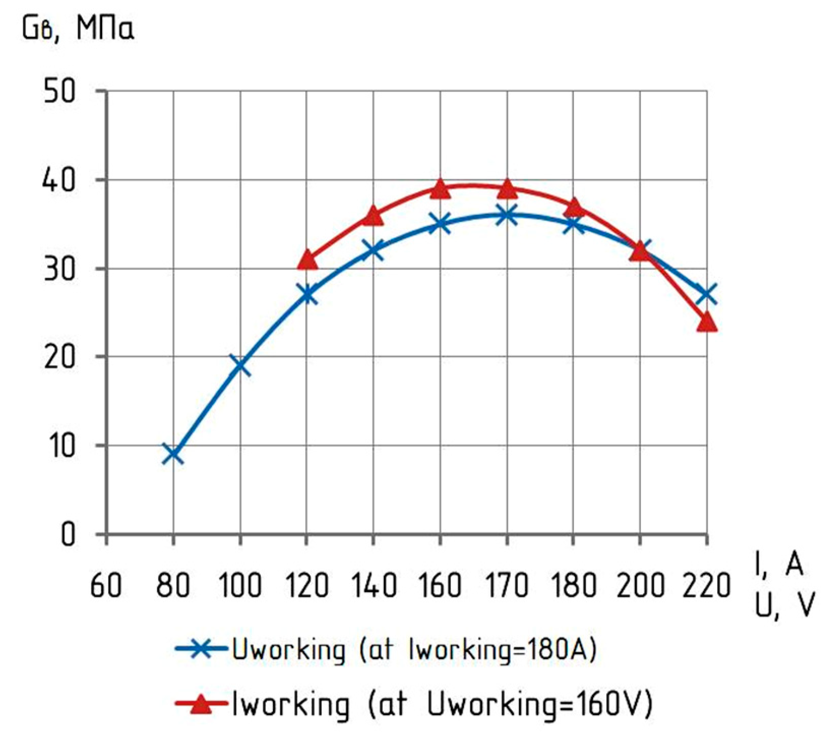
Current and voltage are those technological parameters affecting the thermodynamic processes of optimal coatings formation,
Figure 8.
The optimal values of the current strength, considering the design features of the plasmotron, are proposed to be determined by the following empirical formula [
26]:
where d is the diameter of the outlet of the plasmotron nozzle, mm.
The graph shows that the best option is Uworking = 180–190 V, Iworking = 180–200A.
It was experimentally determined that the cracking and adhesion of the coating is affected by the sputtering mode and the design of the plasmotron. The listed modes (I-current strength-180–200 A, U-voltage–180–190 V, l-spraying distance−120 mm, plasma jet speed—280 m/s, multicomponency, turbulence) can be considered optimal, as they provide a high linear energy of particles, a high mixing coefficient (turbulence), and the introduction of particles to a depth of 0.3–0.5 mm.
One of the final stages of substantiating the effectiveness of plasma reduction is metallographic studies. The results, which confirm the effectiveness of the selected modes of the technological recovery process, affecting the improvement of the phase structure of the surface of the turbine blades.
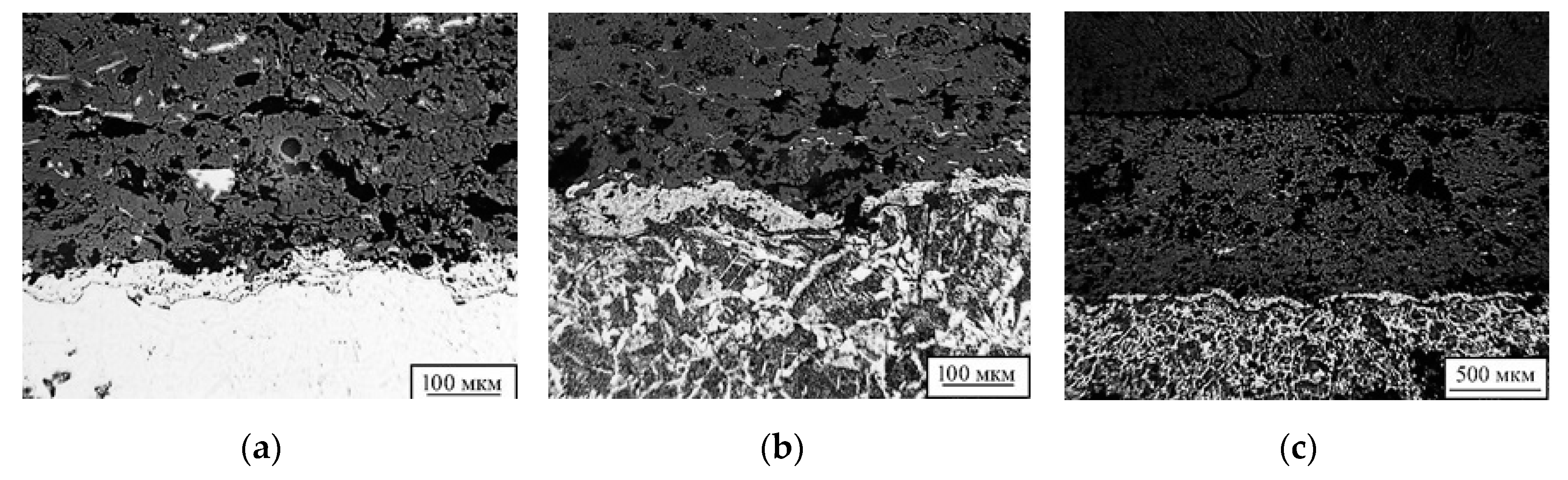
The microstructures of the tested blade samples recovered by plasma spraying are shown in
Figure 9. The studied samples were divided into 3 groups according to the technology used for their recovery.
Sample “1”. A large number of pores and inclusions could be noted in the structure of the deposited material. The thickness of the sprayed layer was 2–3 mm. The microstructure of the deposited metal consisted of medium-needle martensite and doped ferrite formed at the boundaries of the primary austenitic grains during the crystallization of the coating (
Figure 9c). At a distance of 1.0–1.5 mm from the fusion boundary, the structure of the base metal consisted of a mixture of perlite and ferrite. The microhardness of the individual structural components of the deposited metal was in the range of 1300–1500 HV. The porous structure indicated some overheating of the metal during the deposition process and low thermal conductivity of materials which limited the heating of the plasma spraying particles. Two approaches should be used to overcome this issue: changing the main plasma spraying parameters in order to reduce heat input energy; and changing the composition of the substrate powder.
Sample “2”. Pores and additional inclusions were observed in the sample “2”. The thickness of the sprayed layer was 1.8–2.0 mm. The microstructure of the deposited metal consists of large-needle martensite and doped ferrite, but in the fusion zone of the base metal (eutectic ledeburit) medium-needle martensite and doped ferrite were observed. The coarse needle-like structure of the deposited metal, as well as the value of the actual grain of 4–5 points [
29], indicated a slight overheating of the metal during the spraying process. It was necessary to change the main parameters of plasma spraying in order to reduce heat input and thermal-dynamic exposure.
Sample “3”. The thickness of the sprayed layer was 1.8–2.5 mm. The sprayed metal consisted of fine-grained perlite and some ferrite. The microhardness of the coating was 1300–1460 HV. Closer to the fusion boundary, the microhardness reached 1470–1550 HV. This indicated that the rate of energy input in the process of spraying was insufficient for material melting. The absence of ferrite formations, the presence of “unreacted” particles in the deposited metal and insufficient diffusion of carbon from the base metal indicated insufficient heat during the spraying process.
The obtained results made it possible to establish the main factors influencing the formation of high-quality phase structure of martensitic-class material.
With respect to the material of the part, the optimal phase structure can be considered to be medium needle martensite and doped ferrite, on the border with primary austenitic grains. At the same time, there are no defects, and the microhardness is 746–1200 HV.
To improve the energy efficiency of the technological process of recovery of the CHP turbine blades, it is proposed to modernize the plasmotron by developing a vortex dispenser that offers the possibility of using multicomponent powder mixtures. The proposed design simulates the variability of the properties of the resulting surface layer in the spraying process, thereby improving the necessary structural and technological parameters of the restored parts.
5. Conclusions
On the basis of the conducted research, it was established that one of the difficult solved problems was not only the restoration of the initial form of a product but also the formation of the blade base structure and austenitic steels. The established cause-and-effect relationships between the technological regimes and mechanical properties of the material structure made it possible to develop an innovative technology for the restoration of off-grade CHP turbine blades. Its distinctive technological feature is the introduction of an implant and the weld overlaying of a stellite plate with subsequent thermal cycling.
The experiment proved that the structural transformations and the potential of the structure tension shall be controlled in the development of the technological process of turbine blade plasma recovery.
The main technological defects were defined and justified:
- -
High concentration of fatigue stresses as a result of the difference between the thermal expansion coefficients of the sputtered layer and the base surface;
- -
Duration of martensitic transformations in the metal structure.
The optimal regimes of plasma reduction that affect the physical and mechanical properties of the surface of the turbine blades were justified. It was also established that indirect parameters, such as mixing coefficient, spraying distance, and multicomponency of the powder composition have a significant impact on the quality of the coating.

 ,
, 


