Spectral Multiplexing of Fluorescent Endoscopy for Simultaneous Imaging with Multiple Fluorophores and Multiple Fields of View

 , , , and
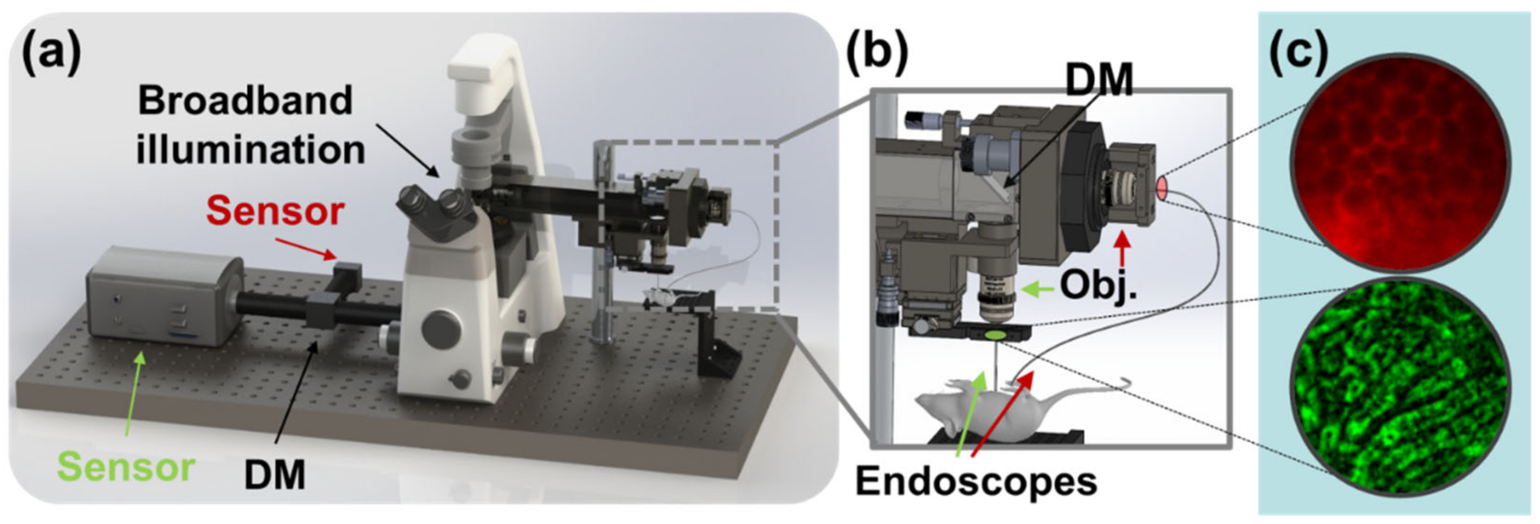
Abstract
:1. Introduction
2. Materials and Methods
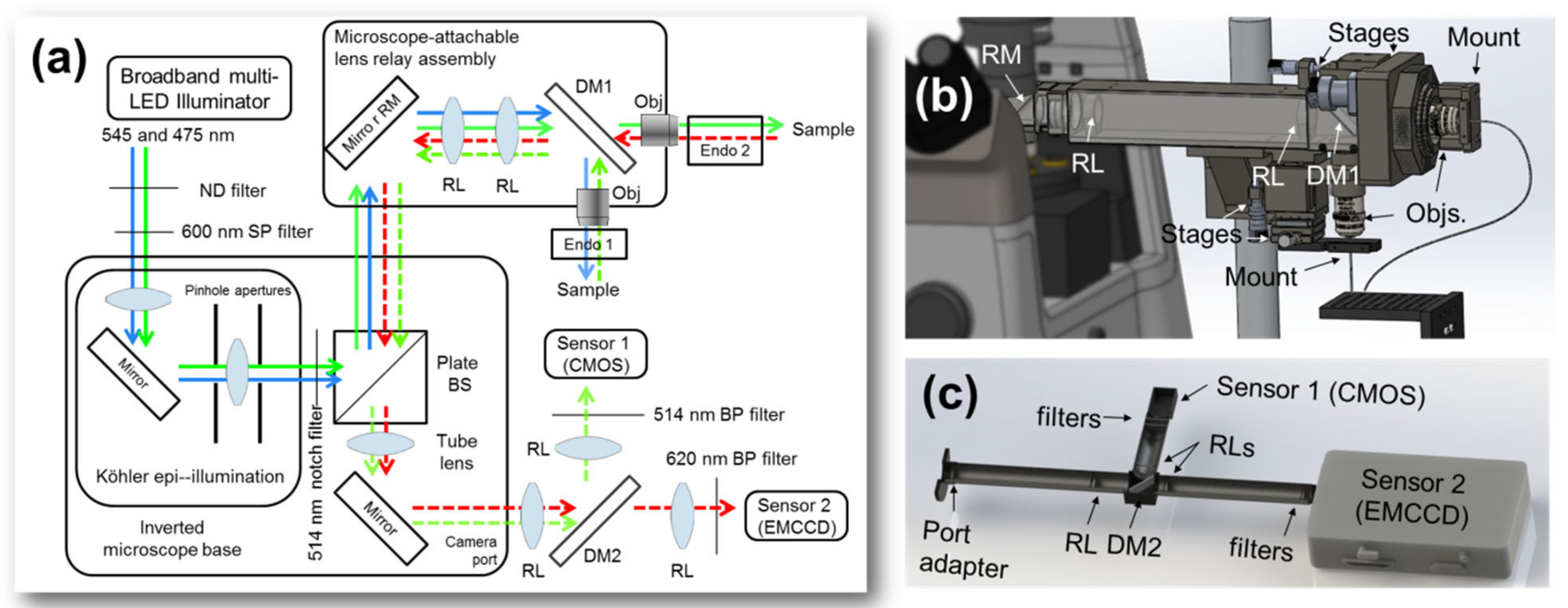
2.1. Illumination and Excitation Filtering
2.2. Attachable Lens Relay Assembly and Spectral Multiplexing
2.3. Objectives and Endoscopes
2.4. Return Imaging Path
2.5. Imaging Sensors
2.6. Imaging Phantom Samples, Reflective and Fluorescent
2.7. Animal Experiments
2.8. Data Analysis
3. Results
3.1. Multiple Microendoscope Probes on a Single Microscope Base
3.2. Crosstalk-Free Spectral Multiplexing
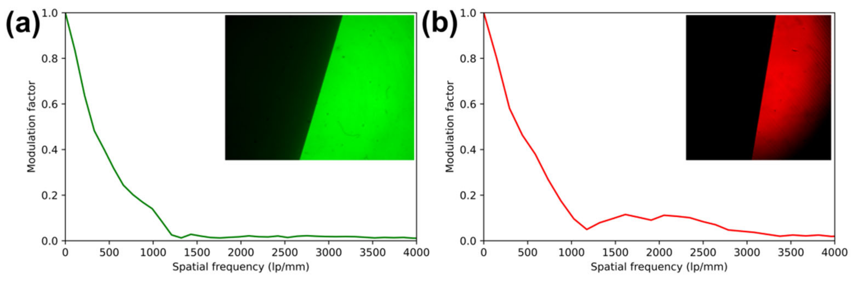
3.3. System Resolution
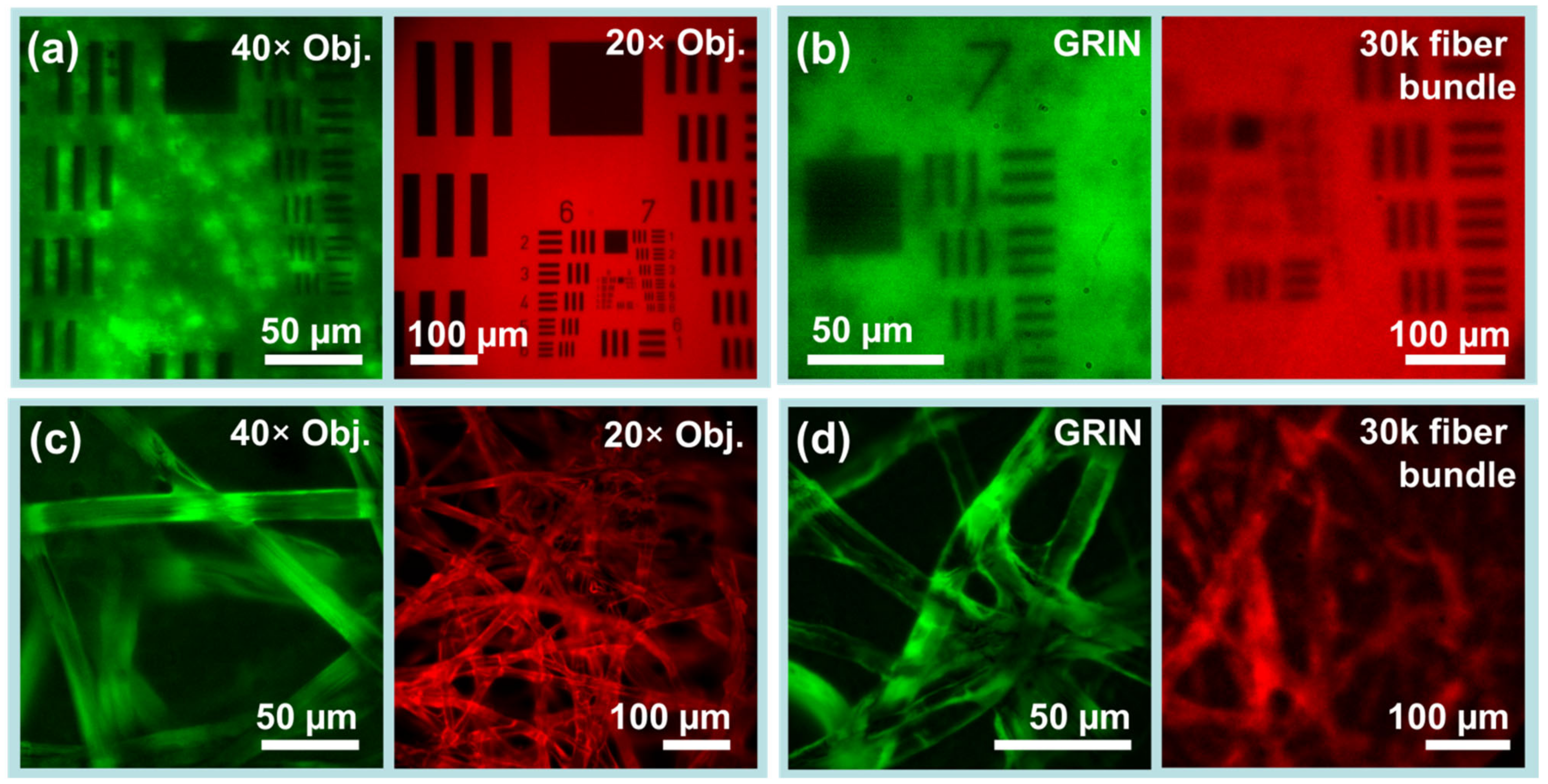
3.4. System Fields of View and Aberrations
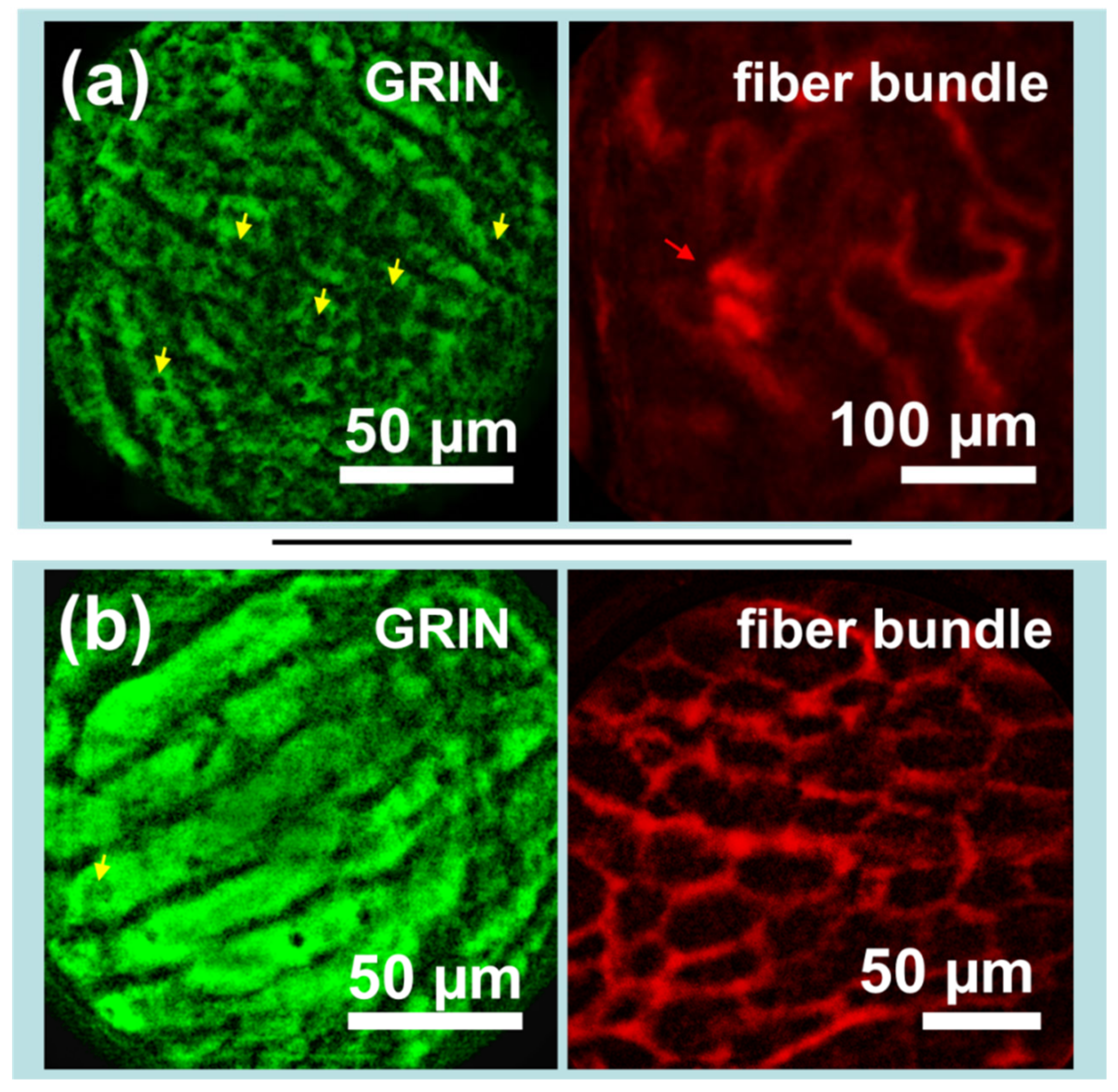
3.5. Imaging Phantoms through GRIN and Flexible Fiber Bundle Microendoscopes
3.6. Demonstration of Simultaneous Liver and Kidney Imaging in Mouse Model
4. Discussion
5. Conclusions
Author Contributions
Funding
Institutional Review Board Statement
Informed Consent Statement
Data Availability Statement
Conflicts of Interest
References
- Hofmeyr, R.; Llewellyn, R.; Fagan, J.J. Multidisciplinary Difficult Airway Challenges: Perioperative Management of Glottic and Supraglottic Tumors. Oper. Tech. Otolaryngol.-Head Neck Surg. 2020, 31, 120–127. [Google Scholar] [CrossRef]
- Zori, A.G.; Jantz, M.A.; Forsmark, C.E.; Wagh, M.S. Simultaneous Dual Scope Endotherapy of Esophago-Airway Fistulas and Obstructions: Simultaneous Two-Scope Endoscopy. Dis. Esophagus 2014, 27, 428–434. [Google Scholar] [CrossRef] [PubMed]
- Dever, J.; Schembre, D.; Brandabur, J.J.; Kozarek, R.A. Novel Use of Simultaneous Dual Endoscopy to Reconstitute Completely Obstructed Esophagi and Colon. Gastrointest. Endosc. 2009, 69, AB230. [Google Scholar] [CrossRef]
- Jamil, L.H.; Huang, B.L.; Kunkel, D.C.; Jayaraman, V.; Soffer, E.E. Successful Gastric Volvulus Reduction and Gastropexy Using a Dual Endoscope Technique. Case Rep. Med. 2014, 2014, 1–3. [Google Scholar] [CrossRef] [PubMed] [Green Version]
- Tekin, A.; Ogetman, Z.; Altunel, E. Laparoendoscopic “Rendezvous” versus Laparoscopic Antegrade Sphincterotomy for Choledocholithiasis. Surgery 2008, 144, 442–447. [Google Scholar] [CrossRef]
- Silva, M.V.; Small, A.C.; Abbott, J.E.; Davalos, J.G. MP68-14 ARE TWO VIEWS BETTER THAN ONE? MULTI-SCOPE PERCUTANEOUS NEPHROLITHOTOMY HAS HIGH STONE CLEARANCE RATES ON POSTOPERATIVE CT. J. Urol. 2018, 199, e922. [Google Scholar] [CrossRef] [Green Version]
- Lecoq, J.; Savall, J.; Vučinić, D.; Grewe, B.F.; Kim, H.; Li, J.Z.; Kitch, L.J.; Schnitzer, M.J. Visualizing Mammalian Brain Area Interactions by Dual-Axis Two-Photon Calcium Imaging. Nat. Neurosci. 2014, 17, 1825–1829. [Google Scholar] [CrossRef] [Green Version]
- de Groot, A.; van den Boom, B.J.; van Genderen, R.M.; Coppens, J.; van Veldhuijzen, J.; Bos, J.; Hoedemaker, H.; Negrello, M.; Willuhn, I.; De Zeeuw, C.I.; et al. NINscope, a Versatile Miniscope for Multi-Region Circuit Investigations. eLife 2020, 9, e49987. [Google Scholar] [CrossRef]
- Kim, P.; Puoris’haag, M.; Côté, D.; Yun, S.H. In Vivo Confocal and Multiphoton Microendoscopy. J. Biomed. Opt. 2008, 13, 010501. [Google Scholar] [CrossRef] [Green Version]
- Paulson, B.; Kim, J.K. Micro-Endoscopy for Live Small Animal Fluorescent Imaging. Adv. Exp. Med. Biol. 2021, 1310, 153–186. [Google Scholar] [CrossRef]
- Paulson, B.; Kim, I.H.; Namgoong, J.-M.; Kim, Y.G.; Lee, S.; Moon, Y.; Shin, D.-M.; Choo, M.-S.; Kim, J.K. Longitudinal Micro-Endoscopic Monitoring of High-Success Intramucosal Xenografts for Mouse Models of Colorectal Cancer. Int. J. Med. Sci. 2019, 16, 1453–1460. [Google Scholar] [CrossRef] [Green Version]
- Kim, J.K.; Lee, W.M.; Kim, P.; Choi, M.; Jung, K.; Kim, S.; Yun, S.H. Fabrication and Operation of GRIN Probes for In Vivo Fluorescence Cellular Imaging of Internal Organs in Small Animals. Nat. Protoc. 2012, 7, 1456–1469. [Google Scholar] [CrossRef] [Green Version]
- Köhler, M.; Paulson, B.; Kim, Y.; Lee, S.; Dicker, A.; van Krieken, P.; Kim, J.Y.; Pack, C.-G.; Joo, J.; Berggren, P.-O.; et al. Integrative Micro-Endoscopic System Combined with Conventional Microscope for Live Animal Tissue Imaging. J. Biophotonics 2018, 11, e201800206. [Google Scholar] [CrossRef]
- Bae, Y.S.; Kim, J.Y.; Kim, J.K. Attachable Micro-Endoscopy System to Conventional Microscope for Live Mouse Organ Imaging Using 4f Configuration. In Optics and Laser Technology, Proceedings of the 5th International Conference on Photonics, Porto, Portugal, 1–27 February 2017; SCITEPRESS—Science and Technology Publications: Setúbal, Portugal, 2017; pp. 137–140. [Google Scholar]
- Edelstein, A.; Amodaj, N.; Hoover, K.; Vale, R.; Stuurman, N. Computer Control of Microscopes Using ΜManager. Curr. Protoc. Mol. Biol. 2010, 92, 14–20. [Google Scholar] [CrossRef] [Green Version]
- Edelstein, A.D.; Tsuchida, M.A.; Amodaj, N.; Pinkard, H.; Vale, R.D.; Stuurman, N. Advanced Methods of Microscope Control Using ΜManager Software. J. Biol. Methods 2014, 1, e10. [Google Scholar] [CrossRef] [Green Version]
- Schneider, C.A.; Rasband, W.S.; Eliceiri, K.W. NIH Image to ImageJ: 25 Years of Image Analysis. Nat. Methods 2012, 9, 671–675. [Google Scholar] [CrossRef]
- Castle, M.; Keller, J.; Schmid, M. Rolling Ball Background Subtraction (ImageJ). 2007. Available online: https://imagej.nih.gov/ij/plugins/rolling-ball.html (accessed on 1 December 2022).
- Sternberg Biomedical Image Processing. Computer 1983, 16, 22–34. [CrossRef]
- Pizer, S.M.; Amburn, E.P.; Austin, J.D.; Cromartie, R.; Geselowitz, A.; Greer, T.; ter Haar Romeny, B.; Zimmerman, J.B.; Zuiderveld, K. Adaptive Histogram Equalization and Its Variations. Comput. Vis. Graph. Image Process. 1987, 39, 355–368. [Google Scholar] [CrossRef]
- Mitja, C.; Escofet, J.; Tacho, A.; Revuelta, R. Slanted Edge MTF (ImageJ). 2011. Available online: https://imagej.nih.gov/ij/plugins/se-mtf/index.html. (accessed on 1 December 2022).
- Ryu, C.-M.; Yu, H.Y.; Lee, H.-Y.; Shin, J.-H.; Lee, S.; Ju, H.; Paulson, B.; Lee, S.; Kim, S.; Lim, J.; et al. Longitudinal Intravital Imaging of Transplanted Mesenchymal Stem Cells Elucidates Their Functional Integration and Therapeutic Potency in an Animal Model of Interstitial Cystitis/Bladder Pain Syndrome. Theranostics 2018, 8, 5610–5624. [Google Scholar] [CrossRef]
- Barson, D.; Hamodi, A.S.; Shen, X.; Lur, G.; Constable, R.T.; Cardin, J.A.; Crair, M.C.; Higley, M.J. Simultaneous Mesoscopic and Two-Photon Imaging of Neuronal Activity in Cortical Circuits. Nat. Methods 2020, 17, 107–113. [Google Scholar] [CrossRef]
- Xu, N.; Harnett, M.T.; Williams, S.R.; Huber, D.; O’Connor, D.H.; Svoboda, K.; Magee, J.C. Nonlinear Dendritic Integration of Sensory and Motor Input during an Active Sensing Task. Nature 2012, 492, 247–251. [Google Scholar] [CrossRef] [PubMed]
- Paulson, B.; Lee, S.; Jue, M.; Lee, K.; Lee, S.; Kim, G.B.; Moon, Y.; Lee, J.Y.; Kim, N.; Kim, J.K. Stereotaxic Endoscopy for the Ocular Imaging of Awake, Freely Moving Animal Models. J. Biophotonics 2020, 13, e201960188. [Google Scholar] [CrossRef] [PubMed]
- Kim, P.; Chung, E.; Yamashita, H.; Hung, K.E.; Mizoguchi, A.; Kucherlapati, R.; Fukumura, D.; Jain, R.K.; Yun, S.H. In Vivo Wide-Area Cellular Imaging by Side-View Endomicroscopy. Nat. Methods 2010, 7, 303–305. [Google Scholar] [CrossRef] [PubMed]
- Aguirre, A.D.; Vinegoni, C.; Sebas, M.; Weissleder, R. Intravital Imaging of Cardiac Function at the Single-Cell Level. Proc. Natl. Acad. Sci. USA 2014, 111, 11257–11262. [Google Scholar] [CrossRef] [Green Version]
- Looney, M.R.; Thornton, E.E.; Sen, D.; Lamm, W.J.; Glenny, R.W.; Krummel, M.F. Stabilized Imaging of Immune Surveillance in the Mouse Lung. Nat. Methods 2011, 8, 91–96. [Google Scholar] [CrossRef] [Green Version]
- Soulet, D.; Lamontagne-Proulx, J.; Aubé, B.; Davalos, D. Multiphoton Intravital Microscopy in Small Animals: Motion Artefact Challenges and Technical Solutions. J. Microsc. 2020, 278, 3–17. [Google Scholar] [CrossRef] [Green Version]
- Alander, J.T.; Kaartinen, I.; Laakso, A.; Pätilä, T.; Spillmann, T.; Tuchin, V.V.; Venermo, M.; Välisuo, P. A Review of Indocyanine Green Fluorescent Imaging in Surgery. Int. J. Biomed. Imaging 2012, 2012, 7. [Google Scholar] [CrossRef] [Green Version]
- Vinegoni, C.; Aguirre, A.D.; Lee, S.; Weissleder, R. Imaging the Beating Heart in the Mouse Using Intravital Microscopy Techniques. Nat. Protoc. 2015, 10, 1802–1819. [Google Scholar] [CrossRef] [Green Version]
- Slotnick, B.M. Stereotaxic Surgical Techniques for the Mouse. Physiol. Behav. 1972, 8, 139–142. [Google Scholar] [CrossRef]


Disclaimer/Publisher’s Note: The statements, opinions and data contained in all publications are solely those of the individual author(s) and contributor(s) and not of MDPI and/or the editor(s). MDPI and/or the editor(s) disclaim responsibility for any injury to people or property resulting from any ideas, methods, instructions or products referred to in the content. |
© 2022 by the authors. Licensee MDPI, Basel, Switzerland. This article is an open access article distributed under the terms and conditions of the Creative Commons Attribution (CC BY) license (https://creativecommons.org/licenses/by/4.0/).
Share and Cite
Paulson, B.; Darian, S.B.; Kim, Y.; Oh, J.; Ghasemi, M.; Lee, K.; Kim, J.K. Spectral Multiplexing of Fluorescent Endoscopy for Simultaneous Imaging with Multiple Fluorophores and Multiple Fields of View. Biosensors 2023, 13, 33. https://doi.org/10.3390/bios13010033
Paulson B, Darian SB, Kim Y, Oh J, Ghasemi M, Lee K, Kim JK. Spectral Multiplexing of Fluorescent Endoscopy for Simultaneous Imaging with Multiple Fluorophores and Multiple Fields of View. Biosensors. 2023; 13(1):33. https://doi.org/10.3390/bios13010033
Chicago/Turabian StylePaulson, Bjorn, Saeed Bohlooli Darian, Youngkyu Kim, Jeongmin Oh, Marjan Ghasemi, Kwanhee Lee, and Jun Ki Kim. 2023. "Spectral Multiplexing of Fluorescent Endoscopy for Simultaneous Imaging with Multiple Fluorophores and Multiple Fields of View" Biosensors 13, no. 1: 33. https://doi.org/10.3390/bios13010033