Topographical Vacuum Sealing of 3D-Printed Multiplanar Microfluidic Structures

 , , , , and
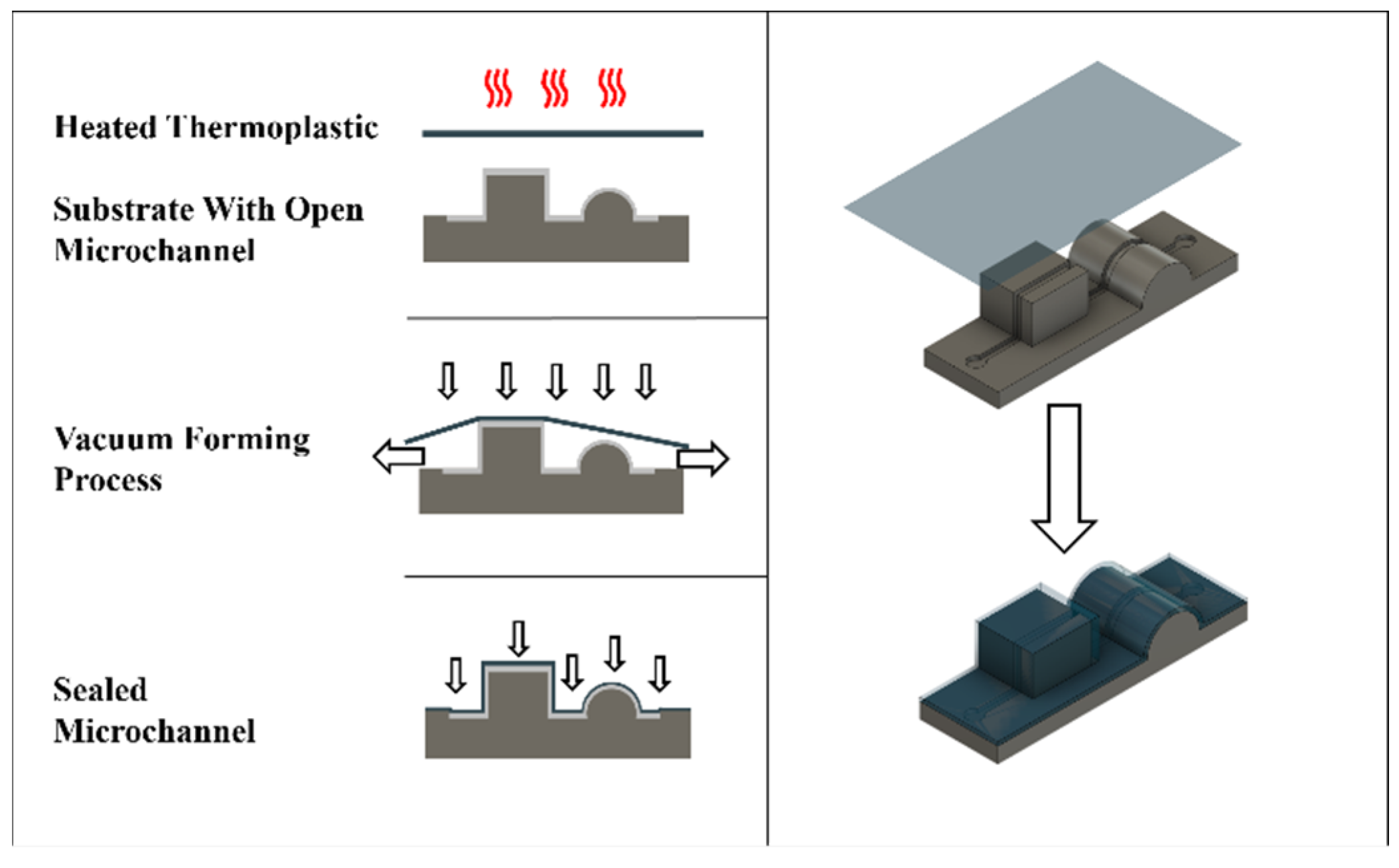
Abstract
:1. Introduction
2. Materials and Methods
2.1. Printing and Vacuum Forming
2.2. Testing Devices
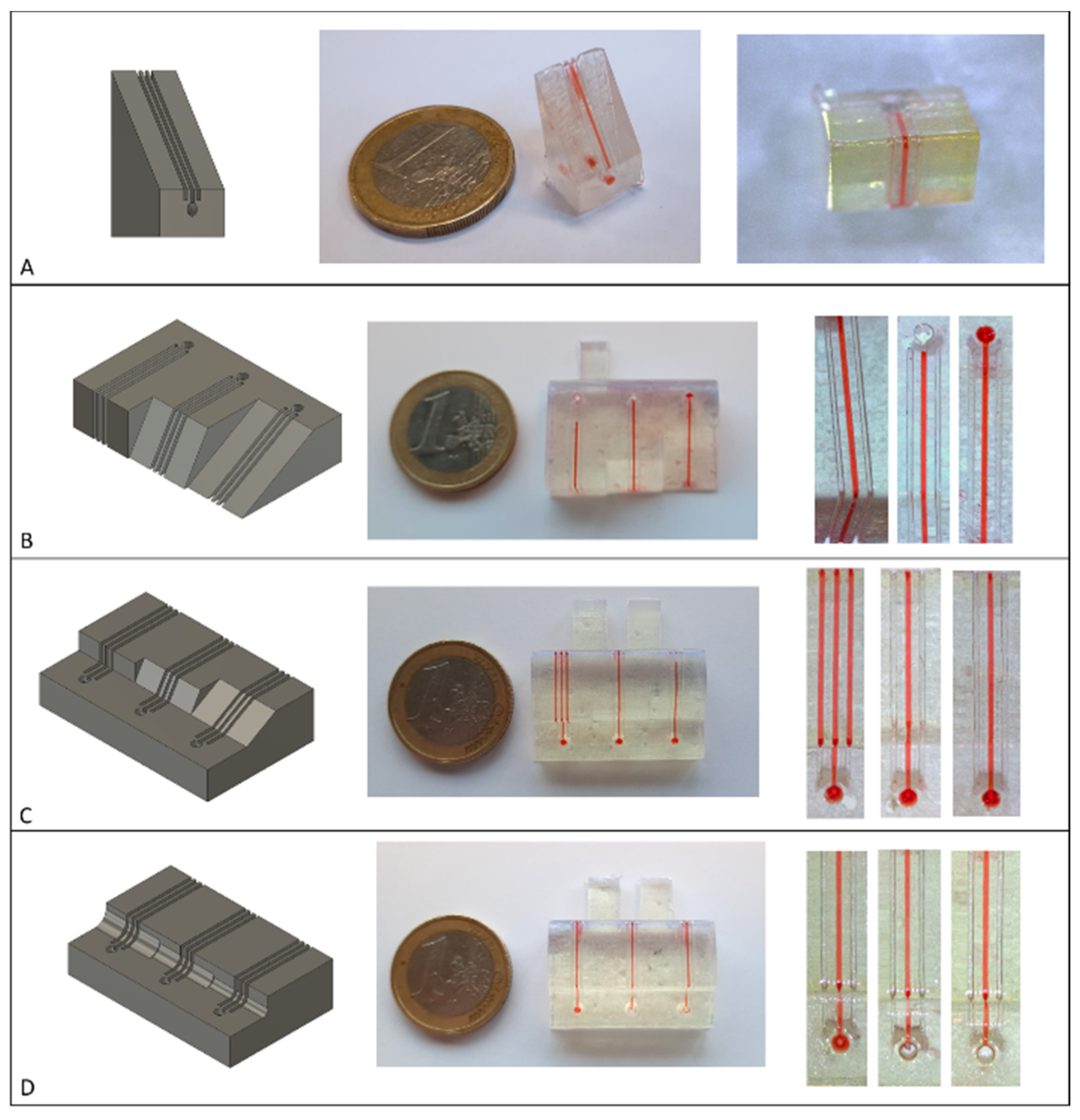
Angle Leakage
2.3. Maximum Working Pressure
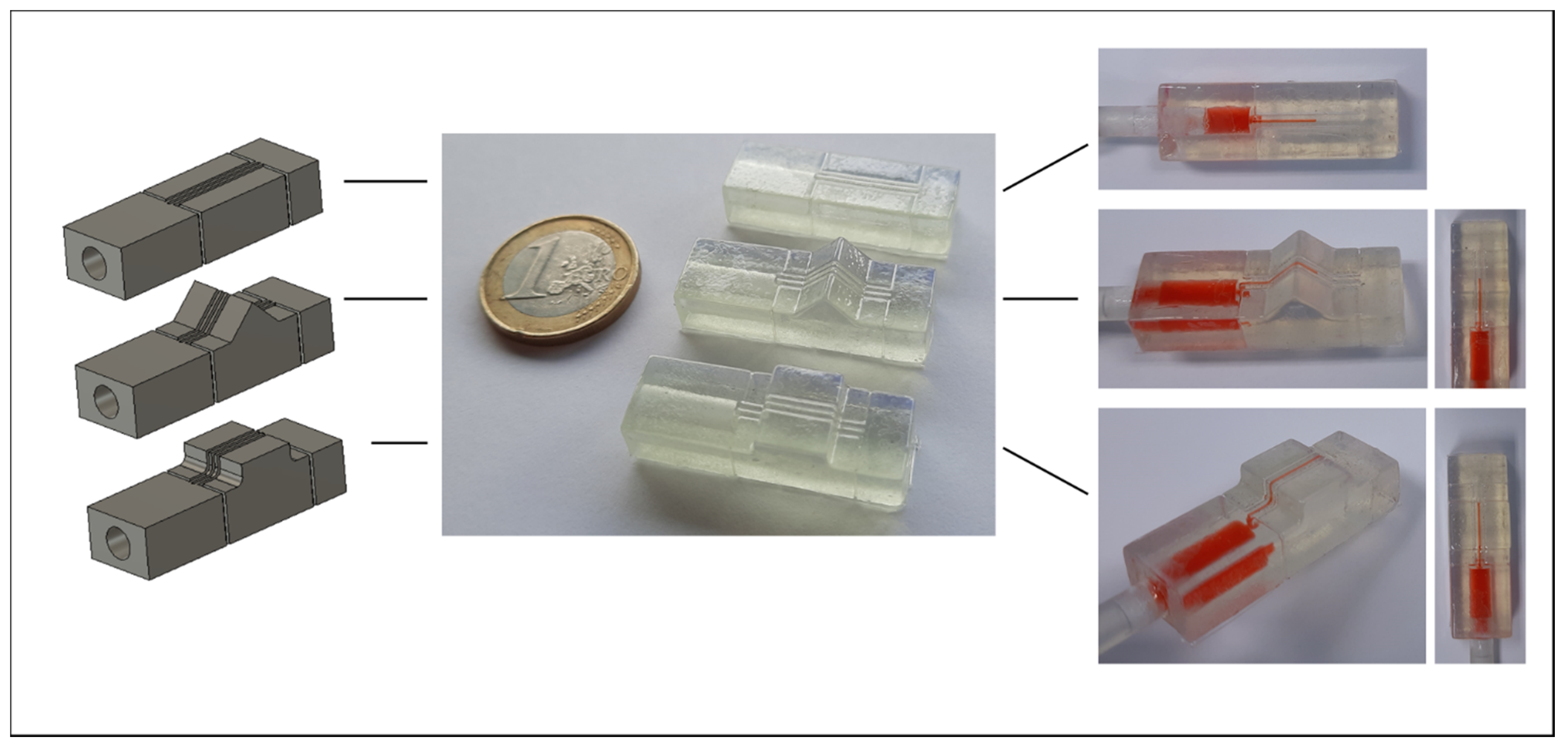
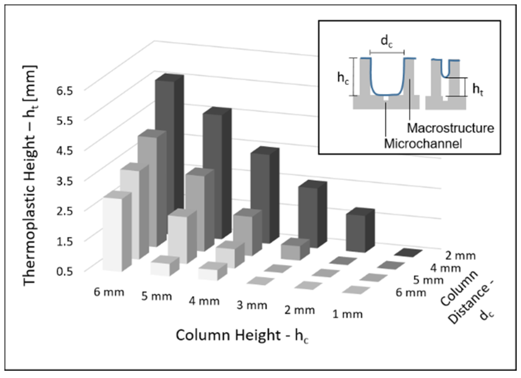
2.4. Column Separation
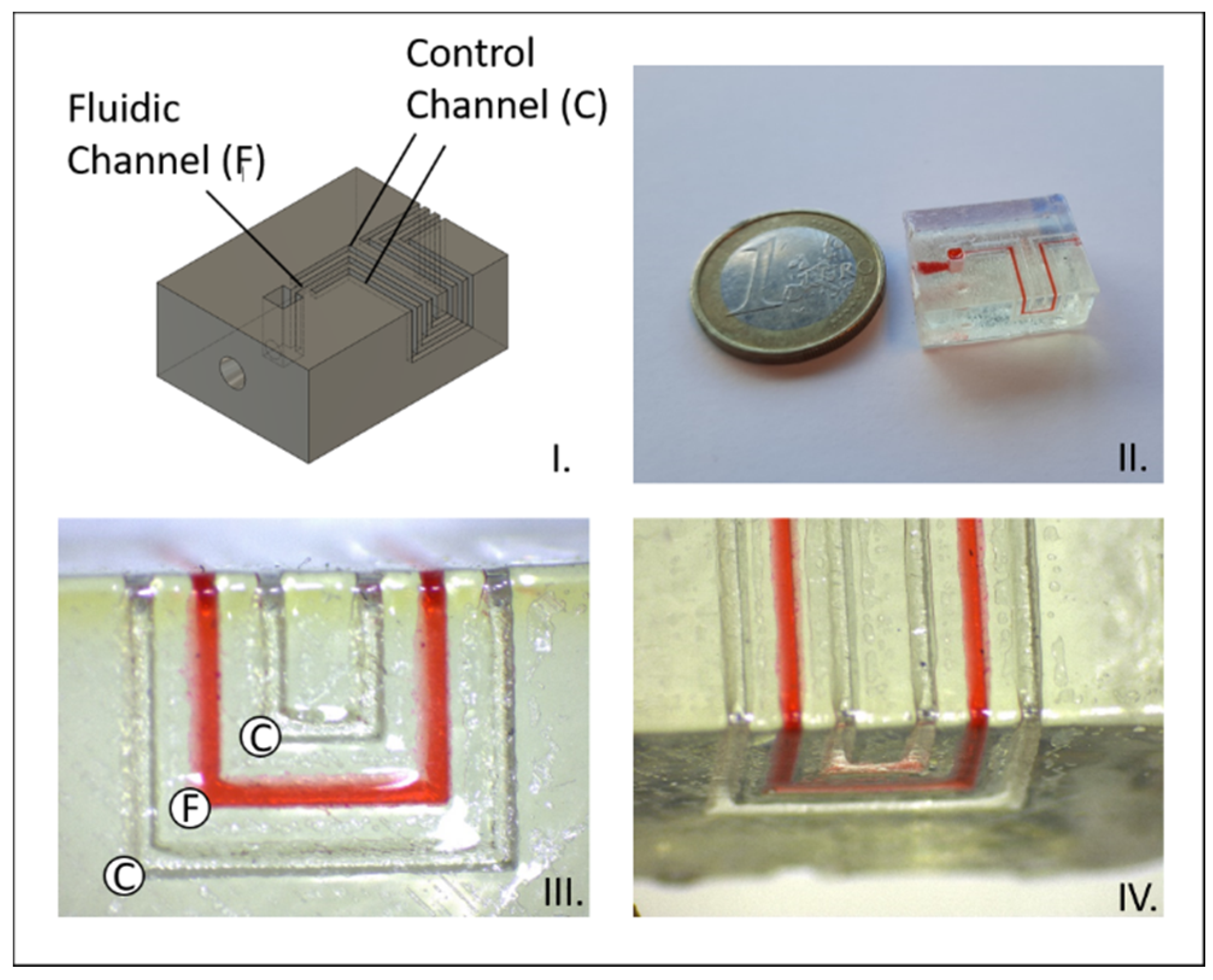
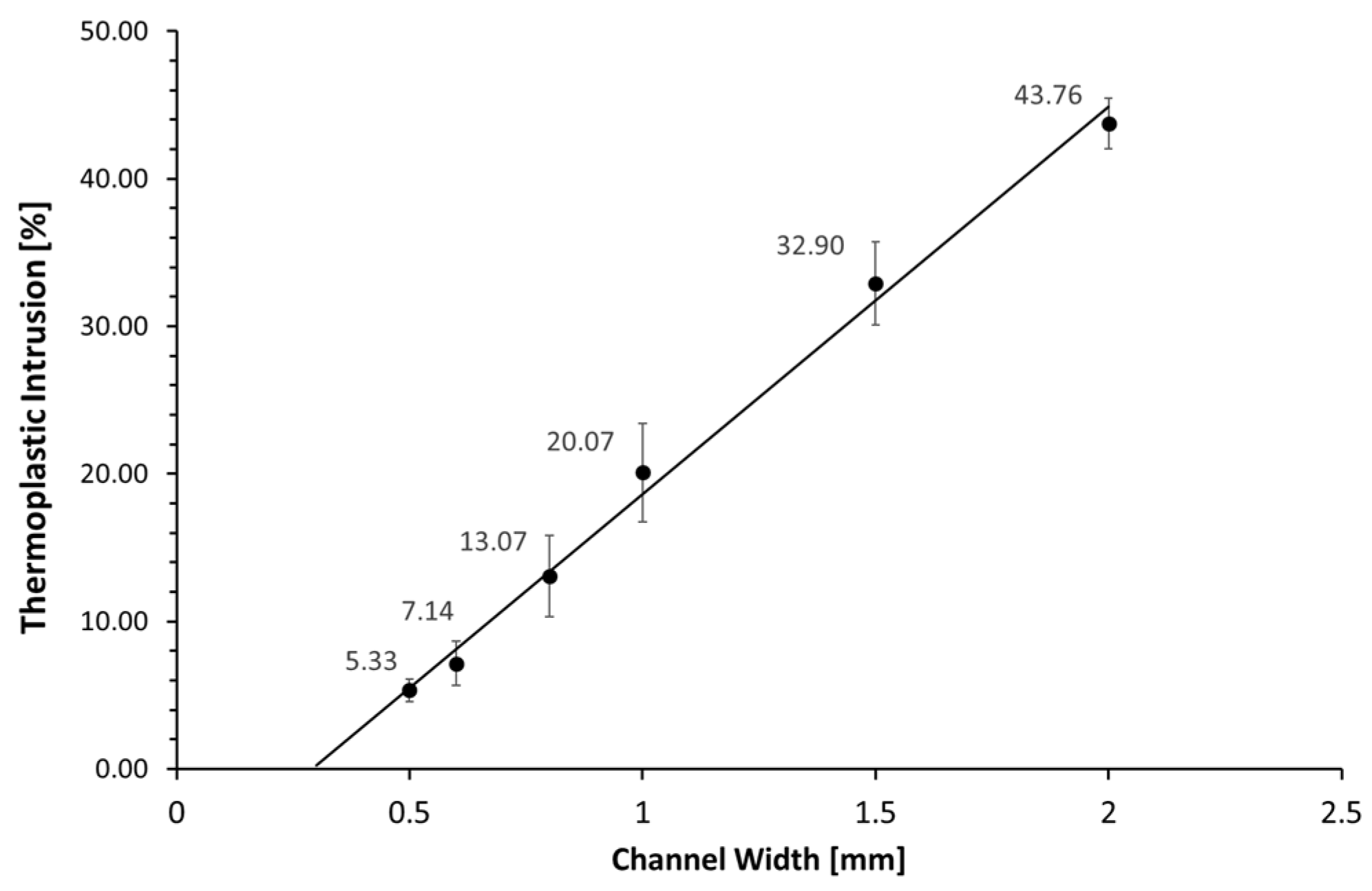
2.5. Channel Intrusion
3. Results
3.1. Angle Leakage
3.2. Maximum Working Pressure
3.3. Column Separation
3.4. Channel Intrusion
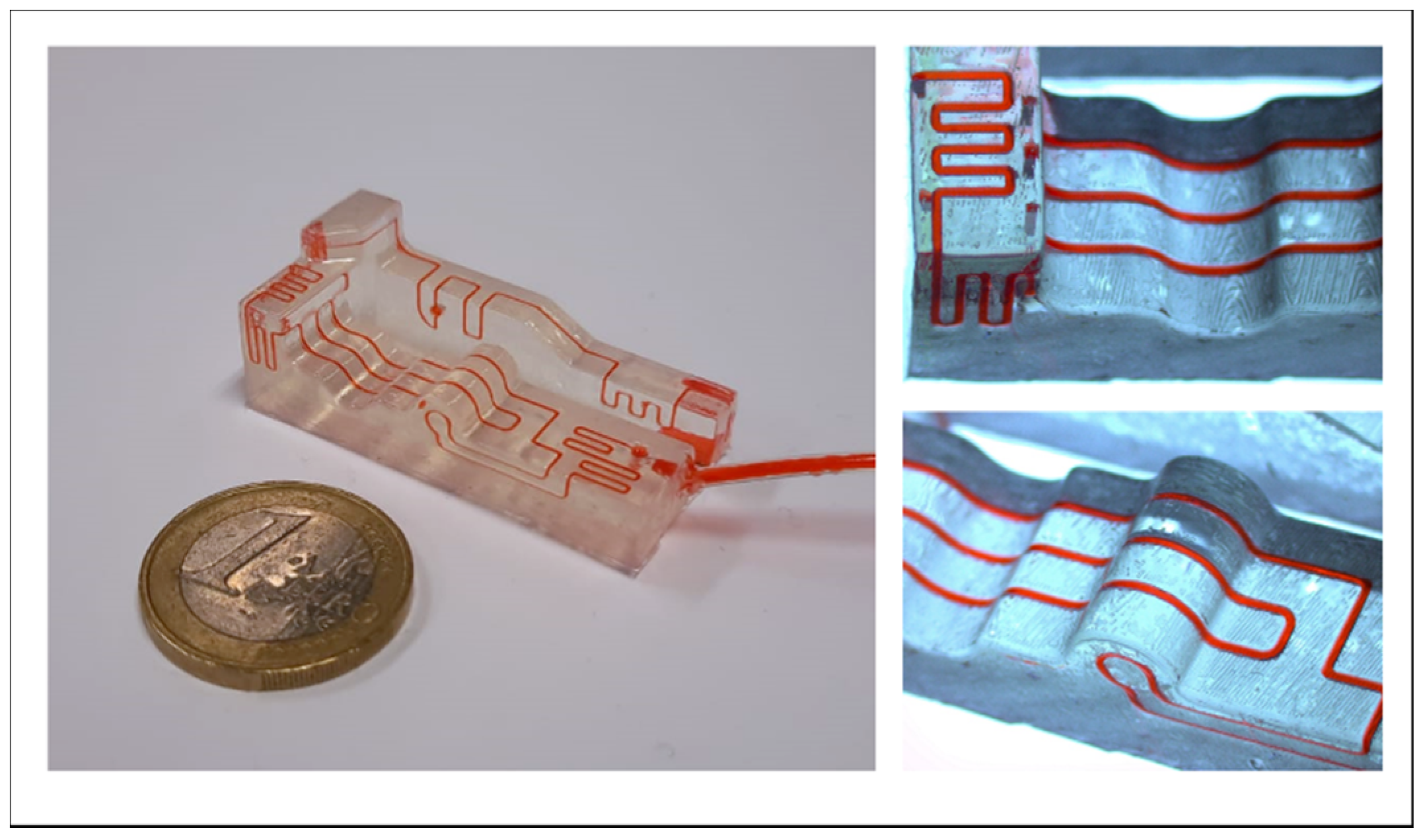
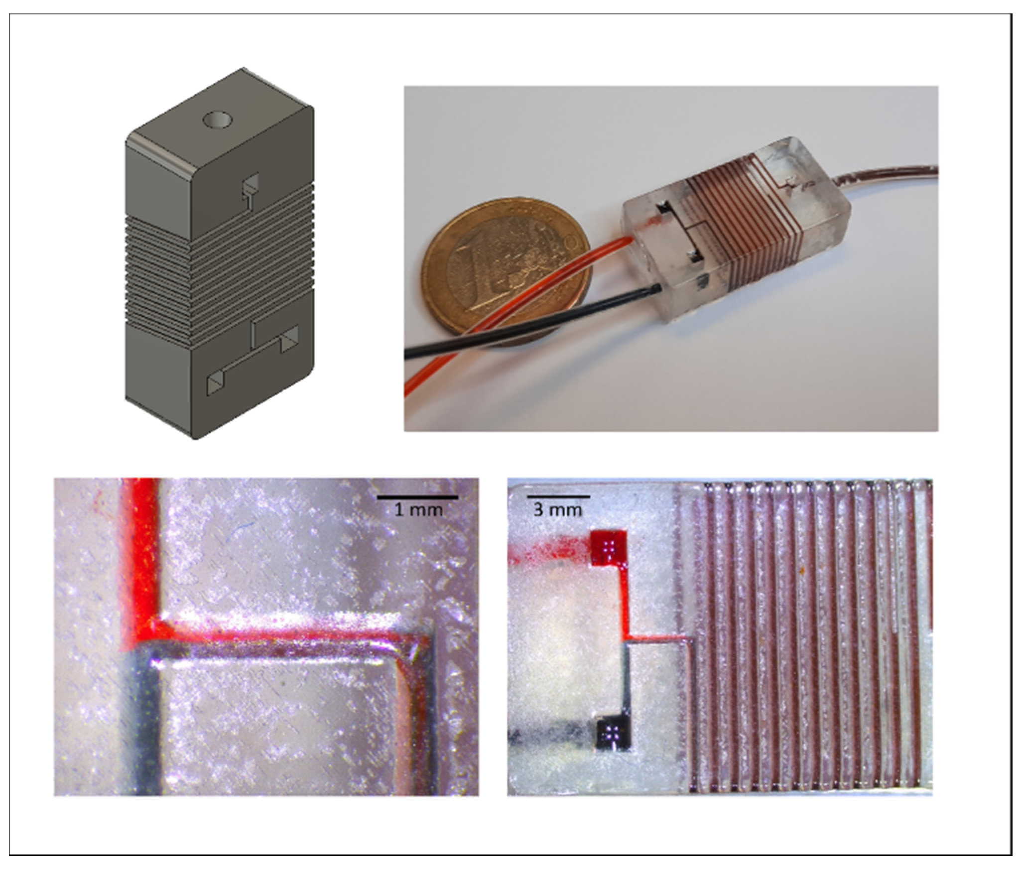
3.5. Application: Roundabout Serpentine Mixer
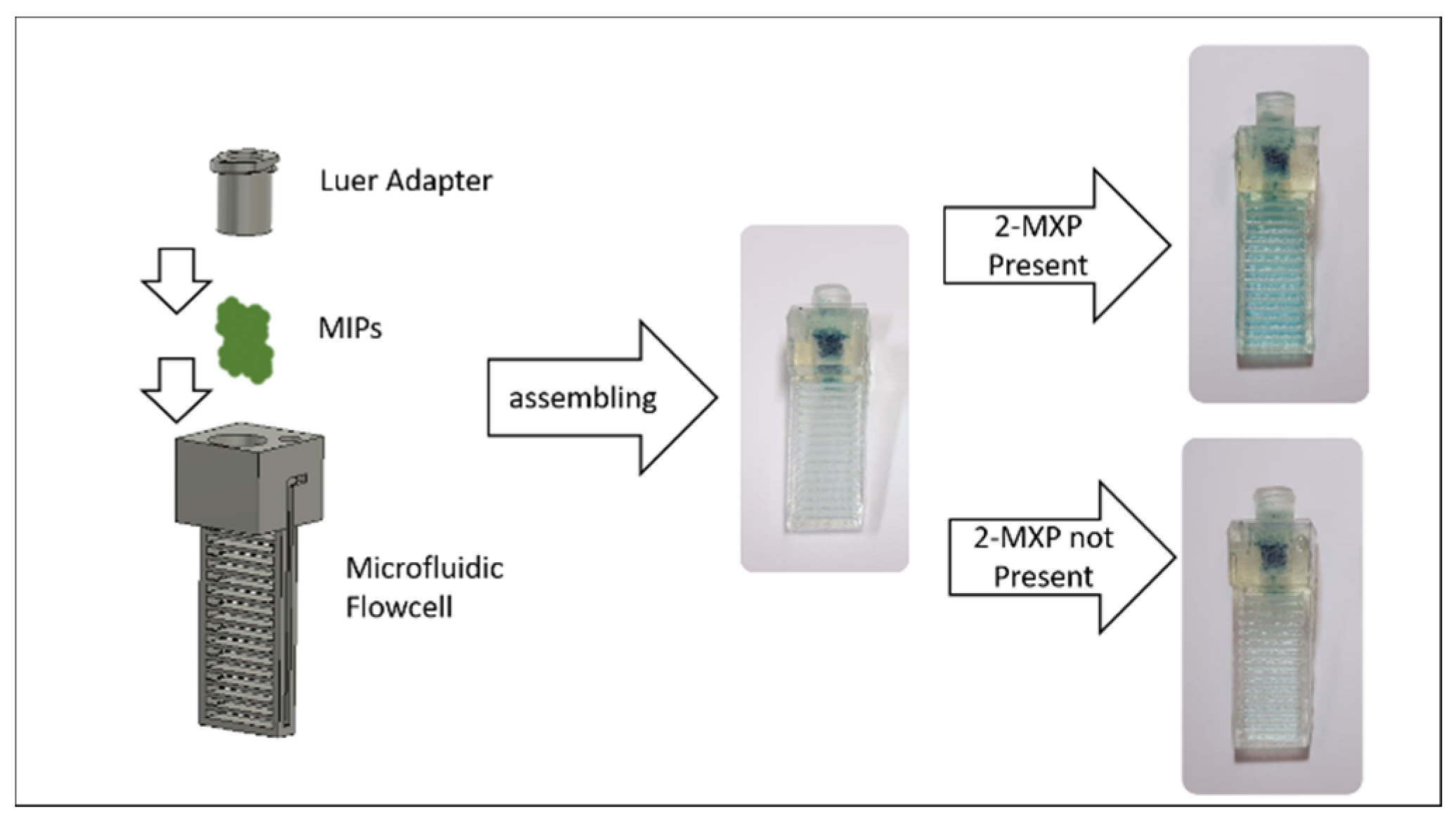
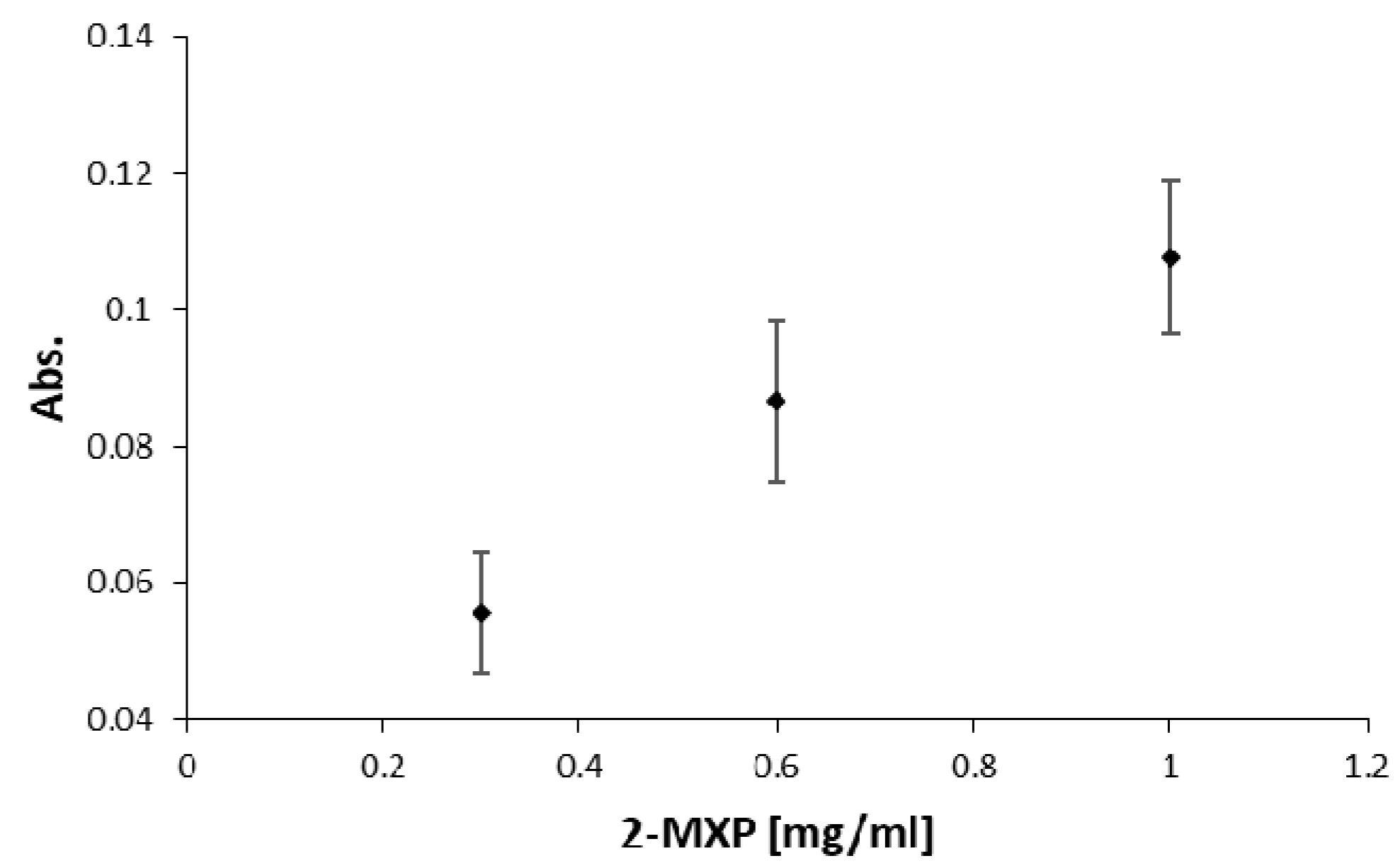
3.6. Application: UV-Vis Cuvette for Colorimetric Biosensing
3.7. Application: Luer-Adapter
4. Discussion
Supplementary Materials
Author Contributions
Funding
Institutional Review Board Statement
Informed Consent Statement
Conflicts of Interest
References
- Convery, N.; Gadegaard, N. 30 years of microfluidics. Micro Nano Eng. 2019, 2, 76–91. [Google Scholar] [CrossRef]
- Faustino, V.; Catarino, S.O.; Lima, R.; Minas, G. Biomedical microfluidic devices by using low-cost fabrication techniques: A review. J. Biomech. 2016, 49, 2280–2292. [Google Scholar] [CrossRef] [PubMed]
- Gale, B.; Jafek, A.; Lambert, C.; Goenner, B.; Moghimifam, H.; Nze, U.; Kamarapu, S. A Review of Current Methods in Microfluidic Device Fabrication and Future Commercialization Prospects. Inventions 2018, 3, 60. [Google Scholar] [CrossRef]
- Walsh, D.I.; Kong, D.S.; Murthy, S.K.; Carr, P.A. Enabling Microfluidics: From Clean Rooms to Makerspaces. Trends Biotechnol. 2017, 35, 383–392. [Google Scholar] [CrossRef] [PubMed]
- Duffy, D.C.; McDonald, J.C.; Schueller, O.J.; Whitesides, G.M. Rapid Prototyping of Microfluidic Systems in Poly(dimethylsiloxane). Anal. Chem. 1998, 70, 4974–4984. [Google Scholar] [CrossRef]
- Nguyen, H.-T.; Thach, H.; Roy, E.; Huynh, K.; Perrault, C.M.-T. Low-Cost, Accessible Fabrication Methods for Microfluidics Research in Low-Resource Settings. Micromachines 2018, 9, 461. [Google Scholar] [CrossRef]
- Do Lago, C.L.; da Silva, H.D.T.; Neves, C.A.; Brito-Neto, J.G.A.; da Silva, J.A.F. A dry process for production of microfluidic devices based on the lamination of laser-printed polyester films. Anal. Chem. 2003, 75, 3853–3858. [Google Scholar] [CrossRef]
- Liu, A.; He, F.; Wang, K.; Zhou, T.; Lu, Y.; Xia, X. Rapid method for design and fabrication of passive micromixers in microfluidic devices using a direct-printing process. Lab Chip 2005, 5, 974–978. [Google Scholar] [CrossRef]
- Thomas, M.S.; Millare, B.; Clift, J.M.; Bao, D.; Hong, C.; Vullev, V.I. Print-and-peel fabrication for microfluidics: What’s in it for biomedical applications? Ann. Biomed. Eng. 2010, 38, 21–32. [Google Scholar] [CrossRef]
- Grimes, A.; Breslauer, D.N.; Long, M.; Pegan, J.; Lee, L.P.; Khine, M. Shrinky-Dink microfluidics: Rapid generation of deep and rounded patterns. Lab Chip 2008, 8, 170–172. [Google Scholar] [CrossRef]
- Sollier, K.; Mandon, C.A.; Heyries, K.A.; Blum, L.J.; Marquette, C.A. “Print-n-Shrink” technology for the rapid production of microfluidic chips and protein microarrays. Lab Chip 2009, 9, 3489–3494. [Google Scholar] [CrossRef] [PubMed]
- Focke, M.; Kosse, D.; Müller, C.; Reinecke, H.; Zengerle, R.; von Stetten, F. Lab-on-a-Foil: Microfluidics on thin and flexible films. Lab Chip 2010, 10, 1365–1386. [Google Scholar] [CrossRef] [PubMed]
- Bartholomeusz, D.A.; Boutte, R.W.; Andrade, J.D. Xurography: Rapid prototyping of microstructures using a cutting plotter. J. Microelectromech. Syst. 2005, 14, 1364–1374. [Google Scholar] [CrossRef]
- Weigl, B.H.; Bardell, R.; Schulte, T.; Battrell, F.; Hayenga, J. Design and Rapid Prototyping of Thin-Film Laminate-Based Microfluidic Devices. Biomed. Microdevices 2001, 3, 267–274. [Google Scholar] [CrossRef]
- Peng, L.; Wu, H.; Shu, Y.; Yi, P.; Deng, Y.; Lai, X. Roll-to-roll hot embossing system with shape preserving mechanism for the large-area fabrication of microstructures. Rev. Sci. Instrum. 2016, 87, 105120. [Google Scholar] [CrossRef]
- Velten, T.; Schuck, H.; Haberer, W.; Bauerfeld, F. Investigations on reel-to-reel hot embossing. Int. J. Adv. Manuf. Technol. 2010, 47, 73–80. [Google Scholar] [CrossRef]
- Weerakoon-Ratnayake, K.M.; O’Neil, C.E.; Uba, F.I.; Soper, S.A. Thermoplastic nanofluidic devices for biomedical applications. Lab Chip 2017, 17, 362–381. [Google Scholar] [CrossRef]
- Disch, A.; Mueller, C.; Reinecke, H. Low cost production of disposable microfluidics by blister packaging technology. Annu. Int. Conf. IEEE Eng. Med. Biol. Soc. 2007, 2007, 6323–6326. [Google Scholar] [CrossRef] [PubMed]
- Focke, M.; Stumpf, F.; Faltin, B.; Reith, P.; Bamarni, D.; Wadle, S.; Müller, C.; Reinecke, H.; Schrenzel, J.; Francois, P.; et al. Microstructuring of polymer films for sensitive genotyping by real-time PCR on a centrifugal microfluidic platform. Lab Chip 2010, 10, 2519–2526. [Google Scholar] [CrossRef]
- Truckenmueller, R.; Giselbrecht, S.; Throne, J.L. Microthermoforming Technology and Applications. Thermoforming Q. 2006, 25, 9–14. [Google Scholar]
- Truckenmüller, R.; Giselbrecht, S.; Rivron, N.; Gottwald, E.; Saile, V.; van den Berg, A.; Wessling, M.; van Blitterswijk, C. Thermoforming of film-based biomedical microdevices. Adv. Mater. 2011, 23, 1311–1329. [Google Scholar] [CrossRef] [PubMed]
- Waheed, S.; Cabot, J.M.; Macdonald, N.P.; Lewis, T.; Guijt, R.M.; Paull, B.; Breadmore, M.C. 3D printed microfluidic devices: Enablers and barriers. Lab Chip 2016, 16, 1993–2013. [Google Scholar] [CrossRef]
- Palmara, G.; Frascella, F.; Roppolo, I.; Chiappone, A.; Chiadò, A. Functional 3D printing: Approaches and bioapplications. Biosens. Bioelectron. 2020, 112849. [Google Scholar] [CrossRef]
- Saggiomo, V.; Velders, A.H. Simple 3D Printed Scaffold-Removal Method for the Fabrication of Intricate Microfluidic Devices. Adv. Sci. 2015, 2, 1500125. [Google Scholar] [CrossRef]
- Heidt, B.; Rogosic, R.; Bonni, S.; Passariello-Jansen, J.; Dimech, D.; Lowdon, J.W.; Arreguin-Campos, R.; Steen Redeker, E.; Eersels, K.; Diliën, H.; et al. The Liberalization of Microfluidics: Form 2 Benchtop 3D Printing as an Affordable Alternative to Established Manufacturing Methods. Phys. Status Solidi A 2020, 217, 1900935. [Google Scholar] [CrossRef]
- Arreguin-Campos, R.; Eersels, K.; Lowdon, J.W.; Rogosic, R.; Heidt, B.; Caldara, M.; Jiménez-Monroy, K.L.; Diliën, H.; Cleij, T.J.; van Grinsven, B. Biomimetic sensing of Escherichia coli at the solid-liquid interface: From surface-imprinted polymer synthesis toward real sample sensing in food safety. Microchem. J. 2021, 169, 106554. [Google Scholar] [CrossRef]
- Heidt, B.; Rogosic, R.; Lowdon, J.W.; Desmond-Kennedy, M.; Jurgaityte, K.; Ferrer Orri, J.; Kronshorst, Y.; Mendez, S.; Polyakova, E.; Rice, H.T.; et al. Biomimetic Bacterial Identification Platform Based on Thermal Transport Analysis Through Surface Imprinted Polymers: From Proof of Principle to Proof of Application. Phys. Status Solidi A 2019, 216, 1800688. [Google Scholar] [CrossRef]
- Lowdon, J.W.; Eersels, K.; Rogosic, R.; Boonen, T.; Heidt, B.; Diliën, H.; van Grinsven, B.; Cleij, T.J. Surface grafted molecularly imprinted polymeric receptor layers for thermal detection of the New Psychoactive substance 2-methoxphenidine. Sens. Actuators A Phys. 2019, 295, 586–595. [Google Scholar] [CrossRef]
- Lowdon, J.W.; Eersels, K.; Rogosic, R.; Heidt, B.; Diliën, H.; Redeker, E.S.; Peeters, M.; van Grinsven, B.; Cleij, T.J. Substrate displacement colorimetry for the detection of diarylethylamines. Sens. Actuators B Chem. 2019, 282, 137–144. [Google Scholar] [CrossRef]
- Lowdon, J.W.; Eersels, K.; Arreguin-Campos, R.; Caldara, M.; Heidt, B.; Rogosic, R.; Jimenez-Monroy, K.L.; Cleij, T.J.; Diliën, H.; van Grinsven, B. A Molecularly Imprinted Polymer-based Dye Displacement Assay for the Rapid Visual Detection of Amphetamine in Urine. Molecules 2020, 25, 5222. [Google Scholar] [CrossRef]
- Rogosic, R.; Heidt, B.; Passariello-Jansen, J.; Björnör, S.; Bonni, S.; Dimech, D.; Arreguin-Campos, R.; Lowdon, J.; Jiménez Monroy, K.L.; Caldara, M.; et al. Modular Science Kit as a support platform for STEM learning in primary and secondary school. J. Chem. Educ. 2021, 98, 439–444. [Google Scholar] [CrossRef]
- Focke, M.; Kosse, D.; Al-Bamerni, D.; Lutz, S.; Müller, C.; Reinecke, H.; Zengerle, R.; von Stetten, F. Microthermoforming of microfluidic substrates by soft lithography (µTSL): Optimization using design of experiments. J. Micromech. Microeng. 2011, 21, 115002. [Google Scholar] [CrossRef]
- Heidt, B.; Siqueira, W.F.; Eersels, K.; Diliën, H.; van Grinsven, B.; Fujiwara, R.T.; Cleij, T.J. Point of Care Diagnostics in Resource-Limited Settings: A Review of the Present and Future of PoC in Its Most Needed Environment. Biosensors 2020, 10, 133. [Google Scholar] [CrossRef] [PubMed]
- Zhang, Y. Three-dimensional-printing for microfluidics or the other way around? Int. J. Bioprint 2019, 5, 192. [Google Scholar] [CrossRef]
- Lee, J.M.; Zhang, M.; Yeong, W.Y. Characterization and evaluation of 3D printed microfluidic chip for cell processing. Microfluid Nanofluid 2016, 20, 5. [Google Scholar] [CrossRef]
- Ruan, X.; Wang, Y.; Kwon, E.Y.; Wang, L.; Cheng, N.; Niu, X.; Ding, S.; van Wie, B.J.; Lin, Y.; Du, D. Nanomaterial-enhanced 3D-printed sensor platform for simultaneous detection of atrazine and acetochlor. Biosens. Bioelectron. 2021, 184, 113238. [Google Scholar] [CrossRef] [PubMed]
- Sathish, S.; Toda-Peters, K.; Shen, A.Q. Proof-of-concept modular fluid handling prototype integrated with microfluidic biochemical assay modules for point-of-care testing. View 2020, 1, e1. [Google Scholar] [CrossRef]
- Elbadawi, M.; Ong, J.J.; Pollard, T.D.; Gaisford, S.; Basit, A.W. Additive Manufacturable Materials for Electrochemical Biosensor Electrodes. Adv. Funct. Mater. 2021, 31, 2006407. [Google Scholar] [CrossRef]
- Feng, F.; He, J.; Li, J.; Mao, M.; Li, D. Multicomponent bioprinting of heterogeneous hydrogel constructs based on microfluidic printheads. Int. J. Bioprint 2019, 5, 202. [Google Scholar] [CrossRef] [PubMed]
- Ortiz-Acosta, D.; Moore, T. Functional 3D Printed Polymeric Materials. In Functional Materials; Sahu, D., Ed.; IntechOpen: London, UK, 2019; ISBN 978-1-78984-057-5. [Google Scholar]


Publisher’s Note: MDPI stays neutral with regard to jurisdictional claims in published maps and institutional affiliations. |
© 2021 by the authors. Licensee MDPI, Basel, Switzerland. This article is an open access article distributed under the terms and conditions of the Creative Commons Attribution (CC BY) license (https://creativecommons.org/licenses/by/4.0/).
Share and Cite
Heidt, B.; Rogosic, R.; Leoné, N.; Brás, E.J.S.; Cleij, T.J.; Harings, J.A.W.; Diliën, H.; Eersels, K.; van Grinsven, B. Topographical Vacuum Sealing of 3D-Printed Multiplanar Microfluidic Structures. Biosensors 2021, 11, 395. https://doi.org/10.3390/bios11100395
Heidt B, Rogosic R, Leoné N, Brás EJS, Cleij TJ, Harings JAW, Diliën H, Eersels K, van Grinsven B. Topographical Vacuum Sealing of 3D-Printed Multiplanar Microfluidic Structures. Biosensors. 2021; 11(10):395. https://doi.org/10.3390/bios11100395
Chicago/Turabian StyleHeidt, Benjamin, Renato Rogosic, Nils Leoné, Eduardo J. S. Brás, Thomas J. Cleij, Jules A. W. Harings, Hanne Diliën, Kasper Eersels, and Bart van Grinsven. 2021. "Topographical Vacuum Sealing of 3D-Printed Multiplanar Microfluidic Structures" Biosensors 11, no. 10: 395. https://doi.org/10.3390/bios11100395