Article

Nanostructured BaCo0.4Fe0.4Zr0.1Y0.1O3-δ Cathodes with Different Microstructural Architectures

by
Lucía dos Santos-Gómez
1,2,*,
Javier Zamudio-García
1,
José M. Porras-Vázquez
1,
Enrique R. Losilla
1 and
David Marrero-López
3,*
1
Dpto. de Química Inorgánica, Universidad de Málaga, Cristalografía y Mineralogía, 29071 Málaga, Spain
2
Department of Physical and Analytical Chemistry, Oviedo University-CINN, 33006 Oviedo, Spain
3
Dpto. de Física Aplicada I, Universidad de Málaga, 29071 Málaga, Spain
*
Authors to whom correspondence should be addressed.
Nanomaterials 2020, 10(6), 1055; https://doi.org/10.3390/nano10061055
Submission received: 29 April 2020 / Revised: 8 May 2020 / Accepted: 9 May 2020 / Published: 30 May 2020

Abstract

:
Lowering the operating temperature of solid oxide fuel cells (SOFCs) is crucial to make this technology commercially viable. In this context, the electrode efficiency at low temperatures could be greatly enhanced by microstructural design at the nanoscale. This work describes alternative microstructural approaches to improve the electrochemical efficiency of the BaCo0.4Fe0.4Zr0.1Y0.1O3-δ (BCFZY) cathode. Different electrodes architectures are prepared in a single step by a cost-effective and scalable spray-pyrolysis deposition method. The microstructure and electrochemical efficiency are compared with those fabricated from ceramic powders and screen-printing technique. A complete structural, morphological and electrochemical characterization of the electrodes is carried out. Reduced values of area specific resistance are achieved for the nanostructured cathodes, i.e., 0.067 Ω·cm2 at 600 °C, compared to 0.520 Ω·cm2 for the same cathode obtained by screen-printing. An anode supported cell with nanostructured BCFZY cathode generates a peak power density of 1 W·cm−2 at 600 °C.

Graphical Abstract

1. Introduction

Although solid oxide fuel cells (SOFCs) are considered as one of the most promising technologies for electrical generation, they typically operate at elevated temperatures (700–1000 °C). This results in several problems for commercial implementation, such as high maintenance costs and premature degradation of the cells components. Therefore, decreasing the operating temperature is one of the principal goals to make this technology commercially viable as well as promoting its potential use in non-stationary energy production systems [1,2,3,4].
The efficiency of SOFC at low operating temperatures is mainly limited by the oxygen reduction reactions (ORR) in the cathode [5,6,7,8]. In the last few years, alternative cathode materials to the traditionally used La0.8Sr0.2MnO3 (LSM) have been investigated, such as La0.6Sr0.4Co0.2Fe0.8O3-δ (LSFC), Ba0.5Sr0.5Co0.8Fe0.2O3-δ (BSCF), GdBaCo2O5+δ, PrBaCo2O5+δ and La2NiO4+δ [9,10,11,12,13,14,15]. However, these cathodes have some drawbacks compared to the traditional LSM. For instance, LSCF suffer from superficial phase segregations at high temperatures, which reduces the ORR activity after long-term operation [16,17]. Layered perovskites with high Co-content exhibit high thermal expansion coefficients compared to the electrolytes; and BSCF degrades over time due to phase transformation from cubic to hexagonal structure [18].
Recently, BaCo0.4Fe0.4Zr0.1Y0.1O3-δ (BCFZY) has been proposed as an efficient cathode material with mixed oxide-ion, proton and electronic conductivity [19,20]. BCFZY was firstly developed as a cathode for proton conductor SOFC; however, it has been recently reported as a favourable material for SOFC, showing attractive chemical and thermal cycling stability [21]. Despite the fruitful findings achieved for this compound, further studies are essential to optimize the microstructure since no investigation has been reported into this field up to now.
The development of new electrodes by microstructural engineering is fundamental to obtaining efficient SOFCs, operating at temperatures below 600 °C. In particular, these should have a stable microstructure, high porosity and surface area, and consequently a long triple phase boundary (TPB) for the ORR [4,22,23]. Diverse strategies have been explored to enhance the cathodic efficiency, including: (i) the infiltration/impregnation method into a porous scaffold, although this is not adequate for mass industrial use due to the multiple fabrication steps required and long time consuming; and (ii) the optimization of the electrode porosity by the use of sacrificial templates, such as polymer and carbon microspheres, or freeze-casting method [24,25]. Alternatively, (iii) the employ of active layers, such as Bi2O3–based films and mixed conductors, improves the oxygen transfer at the electrode/electrolyte interfaces and reduces the ohmic losses [26,27,28].
It is evident that the electrode manufacturing procedures have to be cost-effective, i.e., not time-consuming and easily scalable at an industrial level. Most of the reported preparation methods are tedious and require multiple fabrication steps from the preparation of the electrode powders to deposition and sintering. In this context, spray-pyrolysis deposition has resulted to be an effective method to obtain electrodes over large areas in a single deposition step, reducing considerably the production costs and time. This method has been used to obtain single oxides, such as ZnO and CuO and more complex mixed oxides such as La0.6Sr0.4Co0.2Fe0.8O3-δ and PrBaCo2O5+δ [29,30,31,32,33]. Unlike the physical methods, such as magnetron sputtering and pulsed laser deposition, the cation stoichiometry of the compounds is easily tailored. In addition, the variation of the deposition conditions allows the obtention of electrode microstructures with different morphologies, from dense thin film to thick porous layers.
In this work, we demonstrate that the electrochemical efficiency of the BaCo0.4Fe0.4Zr0.1Y0.1O3-δ cathode is further improved by microstructural architecture design. For this purpose, cost-effective, reproducible and easily scalable preparation methods based on spray-pyrolysis are employed. The structure and morphology have been investigated by X-ray diffraction and electron microscopy. A complete electrochemical study is carried out to understand the electrode mechanism for the ORR as a function of the temperature and the oxygen partial pressure. The results are compared with a traditional cathode obtained from freeze-dried powders and deposited by screen-printing.

2. Materials and Methods

2.1. Materials Synthesis

Ce0.9Gd0.1O1.95 (CGO) was used as electrolyte. Commercial powders (Rhodia, Frankfurt, Germany) were pressed into pellets of 0.1 and 1 cm of thickness and diameter, respectively, and sintered at 1400 °C for 4 h. After that, some of the sintered pellets were symmetrically screen-printed with an ink obtained by mixing CGO and Decoflux (Zschimmer and Schwarz, Villarreal, Spain,) in a 50:50 wt. % ratio, and then sintered at 1100 °C for 1 h to obtain a porous backbone of approximately 7 µm thickness.
For the preparation of the BaCo0.4Fe0.4Zr0.1Y0.1O3-δ (BCFZY) cathode by spray-pyrolysis, the stoichiometric amounts of Ba(NO3)2, Co(NO3)2·6H2O, Fe(NO3)3·9H2O, ZrO(NO3)2·6H2O and Y(NO3)3·6H2O (Merck/Sigma-Aldrich, Barcelona, Spain, purity above 99%) were dissolved in distilled water under continuous stirring. Ethylenediaminetetraacetic acid (EDTA), previously dissolved in diluted NH3, was added in a ligand:metal relation of 1:1 and stirred to obtain a dark-purple solution with a cation concentration of 0.02 mol·L−1. Notice that a diluted precursor solution is need to avoid a rapid growth of the layers, which results in cracked electrodes. The resulting precursor solution was sprayed onto both faces of the CGO pellet with and without porous backbone layers at 300 °C for 1 h. The spray-pyrolysis deposition conditions were similar to those described in detail elsewhere [29]. After that, the electrodes were treated in a furnace in air at 950 °C for 30 min to achieve crystallization.
For comparison purposes, BCFZY powders were prepared using the freeze-drying method [34]. The same cation solution used in the spray-pyrolysis technique, but with a cation concentration of 0.06 mol·L−1, was dropped and fast frozen into liquid nitrogen. The water was gradually sublimated in a Scanvac Coolsafe freeze-dryer for 48 h. The dried powders were put into an oven for two successive thermal treatments, the first one at 300 °C for 1 h to partially decompose the organic material, and the second at 950 °C for 30 min to achieve crystallization. The resulting cathode powders were mixed with Decoflux to obtain an ink, which was screen-printed onto CGO pellets and sintered at 1000 °C for 1 h to ensure appropriate adherence.
Hereafter, for simplicity reasons, the samples will be labelled as: FD for electrodes obtained from freeze-dried precursor powders, SP for spray-pyrolyzed layers onto polished CGO surface, and SP-CGO for spray-pyrolysis onto porous CGO backbones.

2.2. Materials Characterization

X-ray powder diffraction (XRD) were performed by using a PANalytical Empyrean diffractometer (PANalytical, Almelo, The Netherlands) with a CuKα1,2 radiation in the 2θ range of 10–80° for 1 h. Structural analysis by Rietveld method was carried out with the X’Pert HighScore and GSAS suite software (3.0.5, PANalytical, Almelo, The Netherlands ) [35,36].
The morphology and microstructure of the cell components were examined by Field Emission Scanning Electron Microscopy (FE-SEM, Helios Nanolab 650, Hillsboro, OR, USA).
The area specific resistance (ASR) of the symmetrical FD, SP and SP-CGO cells was determined by impedance spectroscopy with a Solartron 1260 impedance/gain-phase analyzer (Hampshire, UK) in the frequency range 0.01−106 Hz. The AC amplitude was varied between 25 and 100 mV, obtaining reproducible results. Pt ink (METALOR® 6082, Metalor, Oullins, France) was painted on both faces of the pellets and fired at 800 °C to obtain a current collector layer. The impedance spectra were recorded as a function of the temperature (400–650 °C) and the oxygen partial pressure (10−3–1 atm) in order to study the different processes involved in the ORR [37,38]. The impedance spectra data were fitted by equivalent circuit models with the ZView software (2.9c, Scribner Associates, Southern Pines, NC, USA) [39].

2.3. Fuel Cell Evaluation

The performance of BCFZY in real fuel cell operating conditions was evaluated by fabricating Ni-CGO/CGO/SP-CGO anode supported cells. Firstly, a NiO-CGO (60:40 wt. %) composite anode was prepared by mixing the corresponding amount of CGO with an aqueous solution of Ni(NO3)2·6H2O (Merck/Sigma-Aldrich 99%). The water was slowly evaporated by heating under constant stirring; the resulting mixture was heated in an oven at 800 °C for 1 h to decompose the nitrates into NiO. Glassy carbon microspheres (15 vol. %) were added to create an adequate porosity. The anode composite was compacted and pre-sintered at 1000 °C for 1 h, obtaining a 13 mm diameter pellet. Secondly, the electrolyte was made by screen-printing a CGO ink onto the NiO-CGO pellet and then cosintered at 1400 °C for 4 h to densify the electrolyte. A porous CGO backbone layer was screen-printed and sintered onto the electrolyte. Finally, BCFZY was deposited by spray-pyrolysis through a shadow mask of 0.25 cm2 and calcined at 950 °C for 30 min.
The NiO-CGO/CGO/SP-CGO cell was mounted in a homemade electrochemical cell and sealed with Ceramabond 668 ceramic paste (Aremco, Northbrook, IL, USA). The current-voltage and impedance curves were acquired with a potentiostat/galvanostat/FRA (Bio-Logic VSP) in the temperature range of 500–600 °C, while air and humidified H2 (3 vol. % H2O) were continuously supplied to the cathode and anode, respectively.

3. Results and Discussion

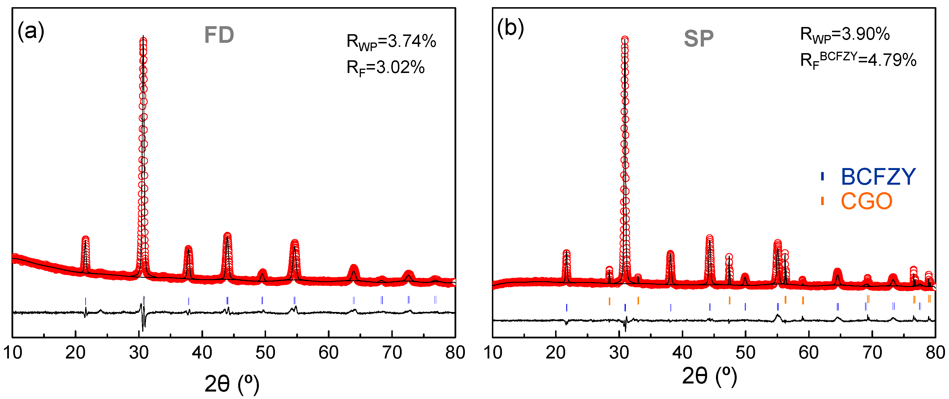
3.1. Structural Analysis

XRD patterns of BCFZY powders and layers prepared from freeze-dried precursors (FD) and spray-pyrolysis onto CGO substrates (SP), respectively, are compared in Figure 1. Both samples are single phases after calcining at 950 °C, showing comparable average crystal sizes, between 30 and 40 nm, which were calculated by the Scherrer equation after correction for instrumental broadening. The similar crystal size is attributed to the identical thermal treatment conditions of FD powders and SP layers. However, the FD electrode suffers a significant grain growth up to 100 nm after screen-printing and sintering at 1000 °C for 1 h, needed to achieve enough adherence with the electrolyte. Thus, SP samples exhibit lower crystal size due to fewer preparation steps and lower sintering temperature, reducing the cation diffusion and the particle growth.
Notice that the XRD data of SP shows two well-differentiated crystalline phases attributed to BCFZY and the CGO substrate (Figure 1b). No secondary phases are observed, which demonstrate a good chemical compatibility between BCFZY and CGO up to the studied temperature, preventing any performance losses.
The Rietveld method was employed to analyze the XRD data. A cubic perovskite type structure (s.g. Pm-3m) and a cubic fluorite (s.g. Fm-3m) were considered for the refinements of BCFZY and CGO, respectively. Occupancy factors were adjusted to the corresponding stoichiometries. Background, scale factor, unit cell, isotropic displacement and peak shape parameters were refined, obtaining low disagreement factors of Rwp = 3.74 and 3.90%; and RF = 3.02 and 4.79% for FD and SP samples, respectively (Figure 1).
Regarding the unit cell parameters, these are similar for both preparation methods ~4.082 Å, which is very close to those reported by other authors ~4.08 Å, indicating that a material with the same structure is obtained [21]. This value is somewhat higher than that reported for isostructural Ba0.5Sr0.5Co0.8Fe0.2O3-δ (BSCF) ~3.98 Å [40].

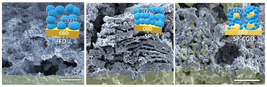
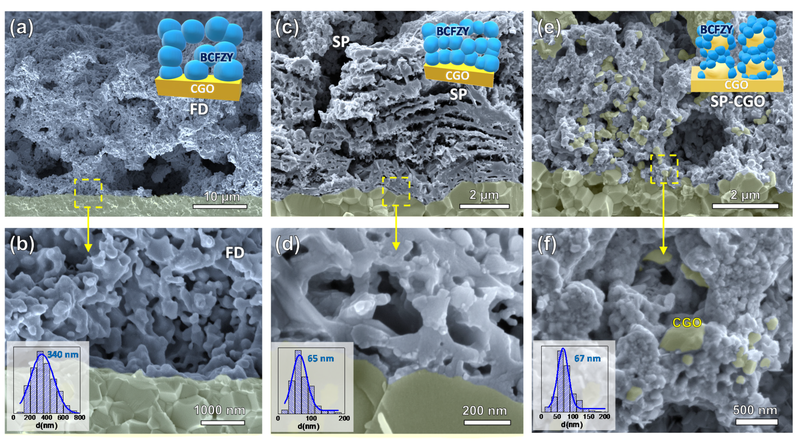
3.2. Morphology of the Electrodes

SEM cross-section images of the three electrode architectures at different magnifications are shown in Figure 2. The BCFZY electrodes prepared by FD and deposited by the traditional screen-printing technique have a thickness of ~25 µm (Figure 2a), presenting a high porosity and constituted by aggregates of particles of approximately 340 nm diameter (Figure 2b).
Electrodes prepared by SP onto polished CGO pellets show much lower thickness, about ~7 µm (Figure 2c). A laminated microstructure is clearly observed due to the multiple spray coating steps and the decomposition of the organic residues after the post-deposition thermal treatment. Such morphologies, typical of a spinodal phase decomposition, have been previously observed in related materials and they are associated with the presence of EDTA in the precursor solution [41]. The SP electrode is highly porous due to the low deposition temperature and the presence of residual organic materials, creating a porous microstructure after the final heat treatment in the furnace. Figure 2d, at higher magnification, shows that the electrode is formed by well sintered particles and strong adherence to the electrolyte, ensuring high mechanical strength and low contact ohmic resistance. The average grain size of 65 nm is much lower than those obtained by the traditional FD method.
BCFZY cathodes deposited by spray-pyrolysis onto a porous CGO backbone have a quite different morphology as can be observed in Figure 2e. The large grains with a diameter of approximately 400 nm correspond to the CGO backbone and the smaller ones are ascribed to BCFZY. Higher magnification SEM images clearly reveal that CGO grains are completely coated by the BCFZY nanoparticles with a size of 67 nm. Thus, this electrode morphology provides an extended triple phase boundary length for the ORR. In addition, the CGO scaffold provides an efficient conduction path for the oxide ion beyond the electrolyte/electrode interface (Figure 2f). It is worth noting that the low deposition temperature and low flow rate used allow the infiltration of the partially decomposed BCFZY precursors into the CGO backbone during the deposition process. This results in a high mass load of BCFZY, ~25 wt. %, in only one step, in contrast to the classical wet infiltration method, where up to 10 impregnation/calcination steps are need to obtain the same active phase loading [42]. Moreover, this method is potentially scalable from lab scale research to industrial scale production, unlike the classical wet infiltration method.

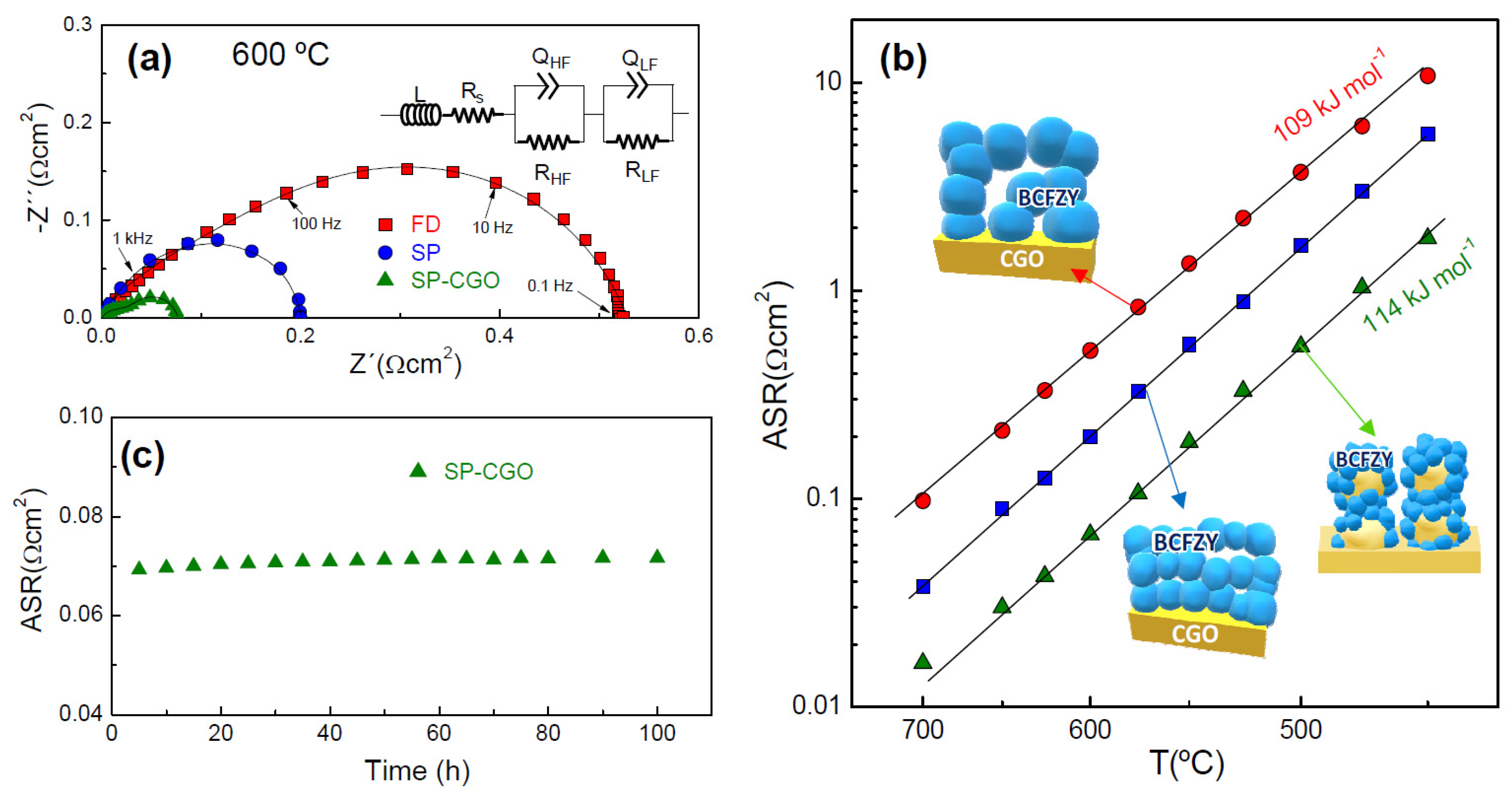
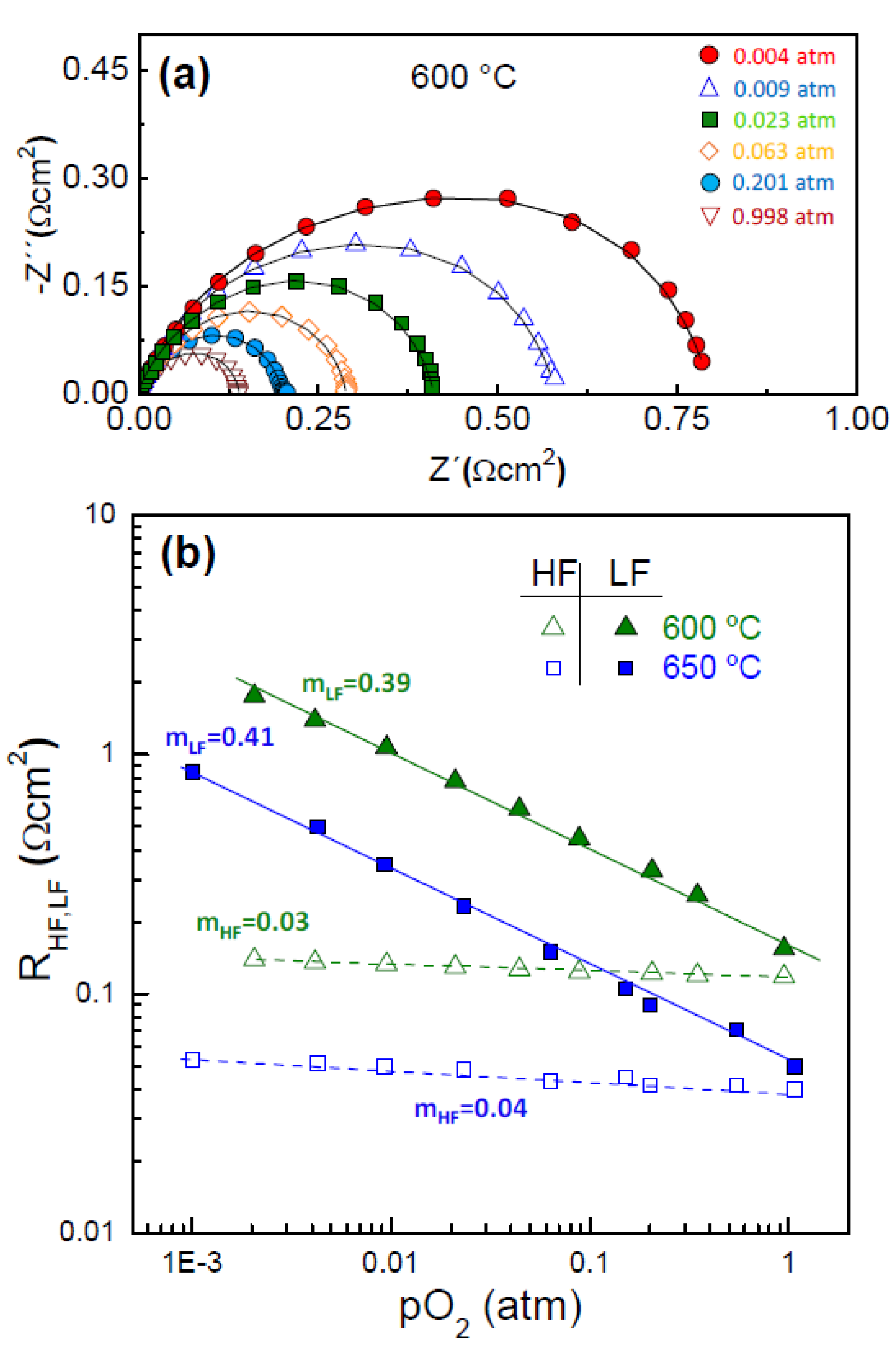
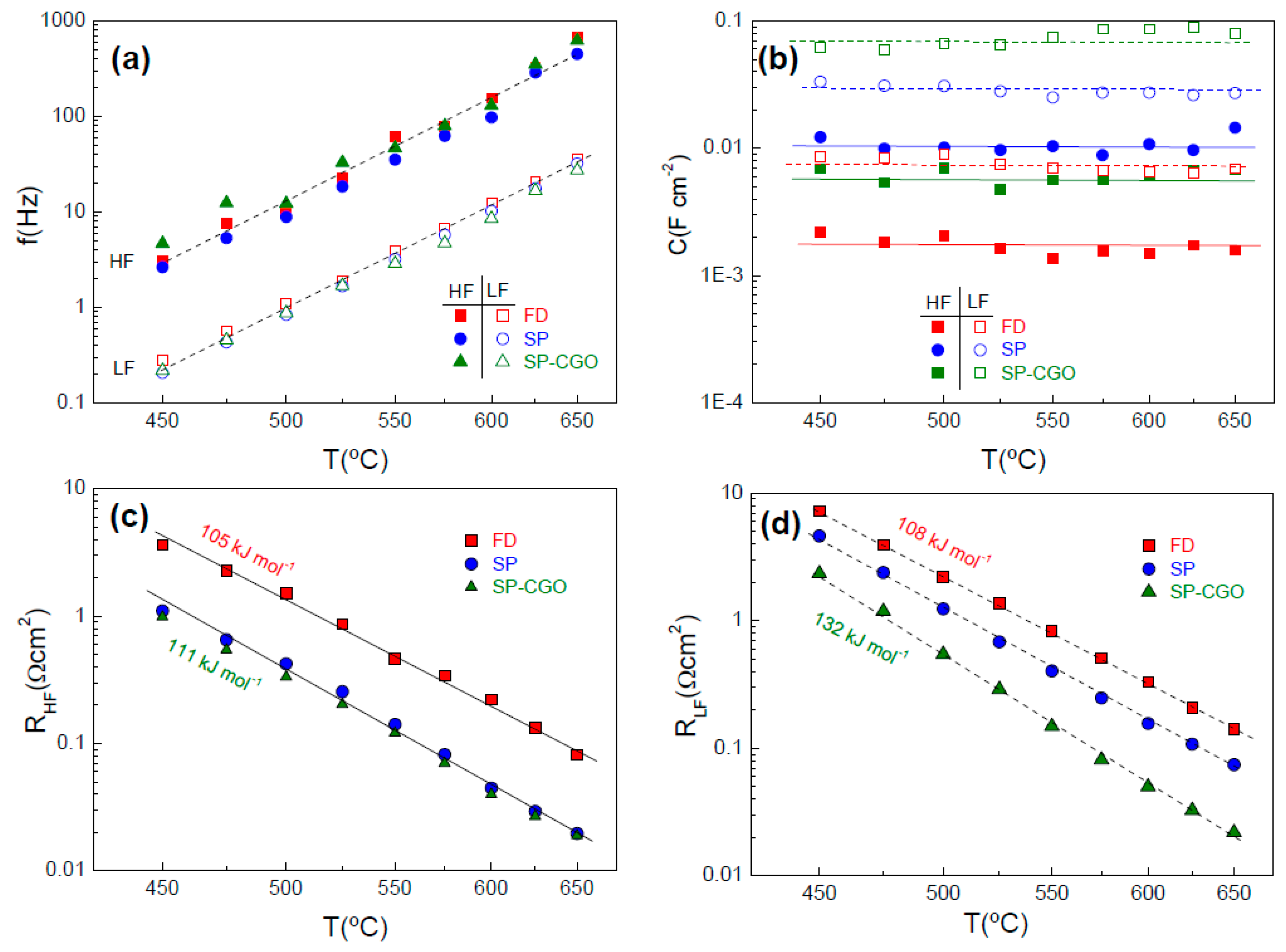
3.3. Electrochemical Properties

Figure 3a shows the impedance spectra for the different electrode architectures at 600 °C in air. Notice that the ohmic resistance was subtracted for better comparison of the electrode polarization response. All the spectra show similar features with two different electrode contributions. Consequently, the spectra were fitted using the equivalent circuit of the inset Figure 3a, where L is an inductor due to the electrochemical setup and Rs a serial resistance associated with the total ohmic losses of the symmetrical cells. Since at least two contributions are discernible in the spectra, two (RQ) elements at high frequency (HF) and low frequency (LF) were used to simulate the electrode response.
Figure 3b compares the area specific resistance (ASR) of the electrodes as a function of the temperature. In the whole temperature range studied, ASR decreases in the order: FD > SP > SP-CGO. All plots are parallel with similar values of activation energy 109−114 kJ·mol−1, which is practically identical to that reported for BSCF, 116 kJ·mol−1 [21,43]. However, the values of activation energies reported in the literature vary in a broad range depending on the preparation method, and electrolyte and gas atmosphere. For instance, Duan et al. reported the lowest value ~79.2 kJ·mol−1 with a CGO20 electrolyte [21]. These values change significantly in dry and wet air for BCFZY in contact with proton-conducting electrolytes, i.e., 111.6 and 80.8 kJ·mol−1, respectively, associated with the presence of proton conductivity in this cathode [19].
Regarding the values of ASR, these decrease from 0.52 Ω·cm2 for FD to 0.067 Ω·cm2 for SP-CGO at 600 °C. Thus, ASR is improved by a factor of 8 by microstructural engineering (Table 1). It is worth noting that these values are lower than those firstly reported by Duan et al. 0.25 Ω·cm2, although the differences are reduced at low temperatures, i.e., 0.54 Ω·cm2 for SP-CGO and 1.1 Ω·cm2 at 500 °C [21].
The ASR values of BCFZY with proton conductor electrolytes are also compared in Table 1. As can be observed, they vary significantly in dry and wet atmospheres. In this case, the results are not directly comparable with those obtained in this study because the electrochemical reaction for ORR may be different for oxide ion and proton-conducting electrolytes. Nevertheless, ASR values in the present work are lower, suggesting that the proposed microstructural designs may be used to improve the performance of proton-conducting SOFCs.
The ASR of SP-CGO remains stable over time, indicating a negligible degradation at least at low operating temperature (Figure 3c).

Contributions of the Electrode Polarization

The overall ORR: 1 2 O 2 + 2 e 2 O 2 is a complex multistep process, which involves gas diffusion, surface adsorption/dissociation and charge transfer reactions [5,6]. Additional reactions take place for mixed proton conductors such as the formation and desorption of H2O and proton migration from electrolyte to TPB. Each of these processes have a different oxygen (pO2) and water partial pressure (pH2O) dependence. Thus, the analysis of the high (RHF) and low (RLF) frequency resistance contributions on the pO2 and pH2O dependence is a useful method to identify the rate limiting steps for ORR, according to [37,38,47]:
R i ( p O 2 ) n ( p H 2 O ) m
If the water partial pressure is constant the following relation is assumed:
R i ( p O 2 ) n
where n provides information about the type of the species involved in ORRs.
Figure 4a displays the impedance spectra of the SP electrode at 600 °C and various pO2 values. All the spectra are composed by two different processes and fitted by using the equivalent circuit of Figure 3a. The variation of the RHF and RLF resistance contributions against the pO2 is shown in Figure 4b. The HF contribution is nearly pO2-independent, suggesting that atomic or molecular oxygen are not involved in this process, and therefore, this is associated with the oxygen ion incorporation from the TPB to the electrolyte, according to: O TPB 2 + V O ¨ O O x . The LF contribution, with n close to 3/8, a high capacitance of 0.1 F·cm−2 and a relaxation frequency in the range of 0.1–10 Hz, is assigned to different elementary reactions in the electrode surface, i.e., atomic oxygen dissociative adsorption and diffusion of atomic oxygen, followed by a charge transfer: O ad + e O [48,49].
The contributions of the electrode polarization were studied separately for a better understanding of the influence of the electrode architecture on the ORR activity. The relaxation frequency of the HF and LF processes present an Arrhenius type behaviour with the temperature with similar values for the different electrode architectures, suggesting that the same processes are involved in the ORR (Figure 5a). The LF contribution appears in the frequency range of 0.1–10 Hz, while the HF process is located at 1–1000 Hz.
The values of capacitance are almost independent on the temperature in the range of 450–650 °C; however, they vary significantly for the different electrodes designs (Figure 5b). For both HF and LF processes, the capacitance increases in the order FD < SP < SP-CGO, which is explained by an increase of the TPB length in agreement with the particle size decrease [50]. The HF contribution, assigned to charge transfer at the BCFZY/CGO interface, has a capacitance between 1.7 mF·cm−2 for FD and 10 mF·cm−2 for SP. The LF process, attributed to reactions in the electrode surface, exhibit a large capacitance of 8 and 70 mF·cm−2 for FD and SP-CGO, respectively.
The Arrhenius representation of the HF and LF resistance contributions are shown in Figure 5c,d. The resistance of the HF process is much lower for those electrodes prepared by spray-pyrolysis deposition. This behaviour could be explained by the smaller particle size of the SP electrodes and reduced fabrication temperature, improving the charger transfer at the BCFZY/CGO interface, and minimizing the cation interdiffusion between the materials layers.
In contrast, the RLF decreases in the following order: FD < SP < SP-CGO, which is clearly attributed to the higher electrode surface and extended TPB length for the electrochemical reactions. The corresponding activation energies are 105–111 kJ·mol−1 for the HF process and somewhat higher 108–132 kJ·mol−1 for LF process (Figure 5c,d).

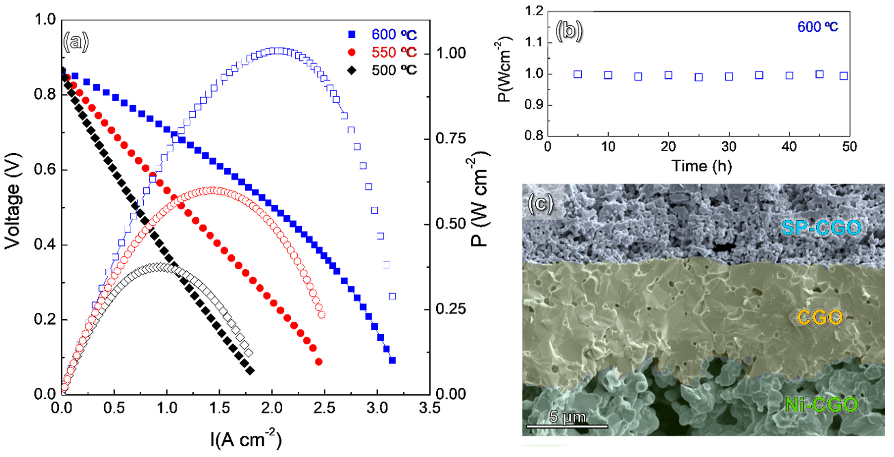
3.4. Fuel Cell Performance

Figure 6a shows the I–V and power density curves of the cells with configuration Ni-CGO/CGO/SP-CGO. The open circuit voltage (OCV) is clearly lower than the theoretical Nernst potential (1.1 V) due to a minor electronic contribution of the CGO electrolyte. However, these are comparable to those previously reported for similar cell configuration, indicating that a leakage in the cell sealing is ruled out [21].
The maximum power densities of the cell are 1.0, 0.6 and 0.38 W·cm−2 at 600, 550 and 500 °C, respectively. These values are higher than those reported for BCFZY cathode in proton conductor SOFC but lower than those reported by Duan et al. 0.97 W·cm2 at 500 °C (Table 1). These differences are possibly explained by the different electrolyte thickness and anode microstructure because the ASR values of BCFZY, obtained in this study, are improved compared to the previous ones [19,20,21,43,44,45,46].
The cell performance was continuously tested for two days and no appreciable performance degradation was observed (Figure 6b). After that the microstructure was examined by SEM, the electrolyte has a thickness of approximately 10 µm and low porosity (Figure 6c). The electrodes are still adequately adhered to the electrolyte without visible formation of cracks or delaminations. It has to be noticed that BCFZY exhibits a thermal expansion coefficient of 21.6 × 10⁻⁶ K−1, higher than that of the CGO electrolyte ~12.5 × 10⁻⁶ K−1 [21], which might leads to mechanical instability after successive thermal cycles. The SP-CGO electrode is formed by a rigid CGO backbone coated with BCFZY particles, and therefore, the physical compatibility issues due to thermal expansion mismatch with the electrolyte are reduced.
In summary, the proposed electrode designs allow to improve the electrochemical performance of BCFZY. In addition, the physical and the chemical compatibility issues with the electrolyte are minimized because the temperature and fabrication steps are reduced compared to traditional method. Moreover, these approaches are economic and suitable for mass production.

4. Conclusions

A spray-deposition method was used to obtain a BCFZY cathode with different microstructural architectures. A BCFZY cathode deposited onto polished CGO electrolyte showed a laminated-type microstructure with high porosity, particle size of 30–90 nm and good adherence to the electrolyte. The cathode prepared by spraying onto a porous CGO backbone is formed by CGO grains coated with BCFZY nanoparticles of 30–80 nm. The reduction in the particle size resulted in extended TPB sites for the electrochemical reactions and lower values of area specific resistance, i.e., 0.52, 0.2 and 0.067 Ω·cm2 at 600 °C for FD, SP and SP-CGO, respectively. The ASR values have been drastically reduced compared to those previously reported in the literature.
The deconvolution of the impedance spectra by equivalent circuits demonstrated that the same processes are presented, regardless of the electrode architecture. The high frequency process, attributed to charge transfer at the electrode/electrolyte interface, was improved for samples prepared by spray-pyrolysis due to the lower fabrication temperature. The low frequency process, assigned to the electrode surface, decreased in the order FD > SP > SP-CGO, confirming a clear relationship between the TPB length and resistance.
A SOFC with the optimized SP-CGO cathode demonstrated a power density of 1.0 and 0.6 W·cm−2 at 600 and 550 °C, respectively. These values are among the highest ones reported for a SOFC with BCFZY as cathode, demonstrating the importance of the microstructural engineering in the enhancement of the SOFC performance.

Author Contributions

Conceptualization: L.d.S.-G. and D.M.-L.; Methodology: L.d.S.-G., J.M.P.-V. and J.Z.-G.; Investigation: L.d.S.-G. and J.Z.-G.; Formal analysis: L.d.S.-G., J.M.P.-V., D.M.-L. and J.Z.-G.; Validation: D.M.-L. and E.R.L.; Visualization: L.d.S.-G. and D.M.-L.; Project administration: D.M.-L.; Writing - original draft: L.d.S.-G. and D.M.-L.; review and editing: J.M.P.-V., J.Z.-G. and E.R.L. All authors have read and agreed to the published version of the manuscript.

Funding

This research was funded by Ministerio de Ciencia, Innovación y Universidades (Spain), grant number RTI2018-093735-B-I00 and UMA18-FEDERJA-033.

Acknowledgments

Lucía dos Santos-Gómez thanks the Ministerio de Ciencia, Innovación y Universidades for her Juan de la Cierva Formación grant (FJC2018-036746-I).

Conflicts of Interest

The authors declare no conflict of interest.

References

  1. Wachsman, E.D.; Lee, K.T. Lowering the temperature of solid oxide fuel cells. Science 2011, 334, 935–939. [Google Scholar] [CrossRef]
  2. Radhika, D.; Nesaraj, A.S. Materials and components for low temperature solid oxide fuel cells – an overview. Int. J. Renew. Energy Dev. 2013, 2, 87–95. [Google Scholar] [CrossRef]
  3. Gao, Z.; Mogni, L.V.; Miller, E.C.; Railsback, J.G.; Barnett, S.A. A perspective on low-temperature solid oxide fuel cells. Energy Environ. Sci. 2016, 9, 1602–1644. [Google Scholar] [CrossRef]
  4. Kan, W.H.; Samson, A.J.; Thangadurai, V. Trends in electrode development for next generation solid oxide fuel cells. J. Mater. Chem. A 2016, 4, 17913–17932. [Google Scholar] [CrossRef] [Green Version]
  5. Fleig, J. Solid oxide fuel cell cathodes: Polarization mechanisms and modeling of the electrochemical performance. Annu. Rev. Mater. Res. 2003, 33, 361–382. [Google Scholar] [CrossRef]
  6. Adler, S.B. Factors governing oxygen reduction in solid oxide fuel cell cathodes. Chem. Soc. Rev. 2004, 104, 4791–4844. [Google Scholar] [CrossRef]
  7. Jacobson, A.J. Materials for solid oxide fuel cells. Chem. Mater. 2010, 22, 660–674. [Google Scholar] [CrossRef]
  8. Azad, A.K.; Kim, J.H.; Irvine, J.T.S. Structure–property relationship in layered perovskite cathode LnBa0.5Sr0.5Co2O5+δ (Ln = Pr, Nd) for solid oxide fuel cells. J. Power Sources 2011, 196, 7333–7337. [Google Scholar] [CrossRef]
  9. Celikbilek, O.; Dessemond, L.; Djurado, E. State-of-the-Art La0.6Sr0.4Co0.2Fe0.8O3-δ cathode for SOFC: Microstructural and electrochemical properties. ECS Trans. 2017, 78, 747–758. [Google Scholar] [CrossRef]
  10. Muñoz-Gil, D.; Pérez-Coll, D.; Peña-Martínez, J.; Garcia-Martín, S. New insights into the GdBaCo2O5+δ material: Crystal structure, electrical and electrochemical properties. J. Power Sources 2014, 263, 90–97. [Google Scholar] [CrossRef]
  11. Zhu, C.; Liu, X.; Yi, C.; Yan, D.; Su, W. Electrochemical performance of PrBaCo2O5+δ layered perovskite as an intermediate-temperature solid oxide fuel cell cathode. J. Power Sources 2008, 185, 193–196. [Google Scholar] [CrossRef]
  12. Egger, A.; Schrödl, N.; Gspan, C.; Sitte, W. La2NiO4+δ as electrode material for solid oxide fuel cells and electrolyzer cells. Solid State Ion. 2017, 299, 18–25. [Google Scholar] [CrossRef]
  13. Choi, S.; Yoo, S.; Kim, J.; Park, S.; Jun, A.; Sengodan, S.; Kim, J.; Shin, J.; Jeong, H.Y.; Choi, Y.M.; et al. Highly efficient and robust cathode materials for low-temperature solid oxide fuel cells: PrBa0.5Sr0.5Co2−xFexO5+δ. Sci. Rep. 2013, 3, 2426. [Google Scholar] [CrossRef] [Green Version]
  14. Efimov, K.; Xu, Q.; Feldhoff, A. Transmission electron microscopy study of Ba0.5Sr0.5Co0.8Fe0.2O3−δ perovskite decomposition at intermediate temperatures. Chem. Mater. 2010, 22, 5866–5875. [Google Scholar] [CrossRef]
  15. Saher, S.; Meffert, M.; Störmer, H.; Gerthsen, D.; Bouwmeester, H.J.M. Grain-size dependence of the deterioration of oxygen transport for pure and 3 mol% Zr-doped Ba0.5Sr0.5Co0.8Fe0.2O3−δ induced by thermal annealing. J. Mater. Chem. A 2017, 5, 4982–4990. [Google Scholar] [CrossRef]
  16. dos Santos-Gómez, L.; Porras-Vázquez, J.M.; Losilla, E.R.; Martín, F.; Ramos-Barrado, J.R.; Marrero-López, D. Stability and performance of La0.6Sr0.4Co0.2Fe0.8O3 nanostructured cathodes with Ce0.8Gd0.2O1.9 surface coating. J. Power Sources 2017, 347, 178–185. [Google Scholar] [CrossRef]
  17. Niania, M.; Podor, R.; Britton, T.B.; Li, C.; Cooper, S.J.; Svetkov, N.; Skinner, S.; Kilner, J. In situ study of strontium segregation in La0.6Sr0.4Co0.2Fe0.8O3−δ in ambient atmospheres using high-temperature environmental scanning electron microscopy. J. Mater. Chem. A 2018, 6, 14120–14135. [Google Scholar] [CrossRef]
  18. Le, M.V.; Tsai, D.S.; Nguyen, T.A. BSCF/GDC as a refined cathode to the single-chamber solid oxide fuel cell based on a LAMOX electrolyte. Ceram. Int. 2018, 44, 1726–1730. [Google Scholar] [CrossRef]
  19. Ren, R.; Wang, Z.; Xu, C.; Sun, W.; Qiao, J.; Rooney, D.W.; Sun, K. Tuning the defects of the triple conducting oxide BaCo0.4Fe0.4Zr0.1Y0.1O3−δ perovskite toward enhanced cathode activity of protonic ceramic fuel cells. J. Mater. Chem. A 2019, 7, 18365–18372. [Google Scholar] [CrossRef]
  20. Duan, C.; Tong, J.; Shang, M.; Nikodemski, S.; Sanders, M.; Ricote, S.; Almansoori, A.; O’Hayre, R. Readily processed protonic ceramic fuel cells with high performance at low temperatures. Science 2015, 349, 1321–1326. [Google Scholar] [CrossRef]
  21. Duan, C.; Hook, D.; Chen, Y.; Tong, J.; O’Hayre, R. Zr and Y co-doped perovskite as a stable, high performance cathode for solid oxide fuel cells operating below 500 °C. Energy Environ. Sci. 2017, 10, 176–182. [Google Scholar] [CrossRef]
  22. Kleitz, M.; Petitbon, F. Optimized SOFC electrode microstructure. Solid State Ion. 1996, 92, 65–74. [Google Scholar] [CrossRef]
  23. Connor, P.A.; Yue, X.; Savaniu, C.D.; Price, R.; Triantafyllou, G.; Cassidy, M.; Kerherve, G.; Payne, D.J.; Maher, R.C.; Cohen, L.F.; et al. Tailoring SOFC Electrode Microstructures for Improved Performance. Adv. Energy Mater. 2018, 8, 1800120. [Google Scholar] [CrossRef]
  24. Liu, Z.; Liu, B.; Ding, D.; Liu, M.; Chen, F.; Xia, C. Fabrication and modification of solid oxide fuel cell anodes via wet impregnation/infiltration technique. J. Power Sources 2013, 237, 243–259. [Google Scholar] [CrossRef]
  25. Liu, Y.; Hashimoto, S.I.; Nishino, H.; Takei, K.; Mori, M.; Suzuki, T.; Funahashi, Y. Fabrication and characterization of micro-tubular cathode-supported SOFC for intermediate temperature operation. J. Power Sources 2007, 174, 95–102. [Google Scholar] [CrossRef]
  26. Park, J.Y.; Wachsman, E.D. Stable and high conductivity ceria/bismuth oxide bilayer electrolytes for lower temperature solid oxide fuel cells. Ionics 2006, 12, 15–20. [Google Scholar] [CrossRef] [Green Version]
  27. Choi, S.; Kucharczyk, C.J.; Liang, Y.; Zhang, X.; Takeuchi, I.; Ji, H.I.; Haile, S.M. Exceptional power density and stability at intermediate temperatures in protonic ceramic fuel cells. Nat. Energy 2018, 3, 202–210. [Google Scholar] [CrossRef] [Green Version]
  28. Zapata-Ramírez, V.; dos Santos-Gómez, L.; Mather, G.C.; Marrero-López, D.; Pérez-Coll, D. Enhanced intermediate-temperature electrochemical performance of air electrodes for solid oxide cells with spray-pyrolyzed active layers. ACS Appl. Mater. Interfaces 2020, 12, 10571–10578. [Google Scholar] [CrossRef]
  29. dos Santos-Gómez, L.; Porras-Vázquez, J.M.; Losilla, E.R.; Marrero-López, D. Improving the efficiency of layered perovskite cathodes by microstructural optimization. J. Mater. Chem. A 2017, 5, 7896–7904. [Google Scholar] [CrossRef]
  30. dos Santos-Gómez, L.; Losilla, E.R.; Martín, F.; Ramos-Barrado, J.R.; Marrero-López, D. Novel microstructural strategies to enhance the electrochemical performance of La0.8Sr0.2MnO3-δ cathodes. ACS Appl. Mater. Interfaces 2015, 7, 7197–7205. [Google Scholar] [CrossRef] [Green Version]
  31. dos Santos-Gómez, L.; Porras-Vázquez, J.M.; Martín, F.; Ramos-Barrado, J.R.; Losilla, E.R.; Marrero-López, D. An easy and innovative method to obtain high efficiency cathodes for Solid Oxide Fuel Cells. J. Power Sources 2016, 319, 48–55. [Google Scholar] [CrossRef]
  32. Zhang, S.L.; Yu, H.X.; Li, C.X.; Lai, S.Y.; Li, C.J.; Yang, G.J.; Sun, H.B.; Wei, T.; Liu, M. Thermally sprayed high-performance porous metal-supported solid oxide fuel cells with nanostructured La0.6Sr0.4Co0.2Fe0.8O3−δ cathodes. J. Mater. Chem. A 2016, 4, 7461–7468. [Google Scholar] [CrossRef]
  33. Hong, T.; Lee, S.; Ohodnicki, P.R.; Brinkman, K. A highly scalable spray coating technique for electrode infiltration: Barium carbonate infiltrated La0.6Sr0.4Co0.2Fe0.8O3-δ perovskite structured electrocatalyst with demonstrated long term durability. Int. J. Hydrogen Energy 2017, 42, 24978–24988. [Google Scholar] [CrossRef]
  34. dos Santos-Gómez, L.; Compana, J.M.; Bruque, S.; Losilla, E.R.; Marrero-López, D. Symmetric electrodes for solid oxide fuel cells based on Zr-doped SrFeO3−δ. J. Power Sources 2015, 279, 419–427. [Google Scholar] [CrossRef]
  35. PANalytical X′Pert HighScore Plus; Malvern Panalytical: Almelo, The Netherlands, 2014.
  36. Larson, A.C.; von Dreele, R.B. General Structure Analysis System (GSAS); Los Alamos National Laboratory: Los Alamos, NM, USA, 1994.
  37. Escudero, M.J.; Aguadero, A.; Alonso, J.A.; Daza, L. A kinetic study of oxygen reduction reaction on La2NiO4 cathodes by means of impedance spectroscopy. J. Electroanal. Chem. 2007, 611, 107–116. [Google Scholar] [CrossRef]
  38. Chen, X.J.; Khor, K.A.; Chan, S.H. Identification of O2 reduction processes at yttria stabilized zirconia vertical bar doped lanthanum manganite interface. J. Power Sources 2003, 123, 17–25. [Google Scholar] [CrossRef]
  39. Johnson, D. ZView: A Software Program for IES Analysis; Version 2.9; Scribner Associates Inc.: Southern Pines, NC, USA, 2005. [Google Scholar]
  40. Koster, H.; Mertins, F.H.B. Powder diffraction of the cubic perovskite Ba0.5Sr0.5Co0.8Fe0.2O3−δ. Powder Diffr. 2003, 18, 56–59. [Google Scholar] [CrossRef]
  41. dos Santos-Gómez, L.; Porras-Vázquez, J.M.; Martín, F.; Ramos-Barrado, J.R.; Losilla, E.R.; Marrero-López, D. A novel multilaminated composite cathode for solid oxide fuel cells. Ceram. Int. 2019, 45, 18124–18127. [Google Scholar] [CrossRef]
  42. Fan, H.; Keane, M.; Li, N.; Tang, D.; Singh, P.; Han, M. Electrochemical stability of La0.6Sr0.4Co0.2Fe0.8O3-δ-infiltrated YSZ oxygen electrode for reversible solid oxide fuel cells. Int. J. Hydrogen Energy 2014, 39, 14071–14078. [Google Scholar] [CrossRef]
  43. Shao, Z.; Haile, S. A high-performance cathode for the next generation of solid-oxide fuel cells. Nature 2004, 431, 170–173. [Google Scholar] [CrossRef]
  44. Qi, H.; Zhao, Z.; Tu, B.; Cheng, M. Reaction tuned formation of hierarchical BaCo0.4Fe0.4Zr0.1Y0.1O3-δ cathode. J. Power Sources 2020, 455, 227971. [Google Scholar] [CrossRef]
  45. Yu, Y.; Yu, L.; Shao, K.; Li, Y.; Maliutina, K.; Yuan, W.; Wu, Q.; Fan, L. BaZr0.1Co0.4Fe0.4Y0.1O3-SDC composite as quasi-symmetrical electrode for proton conducting solid oxide fuel cells. Ceram. Int. 2020, 46, 11811–11818. [Google Scholar] [CrossRef]
  46. Wei, K.; Li, N.; Wu, Y.; Song, W.; Wang, X.; Guo, L.; Khan, M.; Wang, S.; Zhou, F.; Ling, Y. Characterization and optimization of highly active and Ba-deficient BaCo0.4Fe0.4Zr0.1Y0.1O3-δ-based cathode materials for protonic ceramics fuel cells. Ceram. Int. 2019, 45, 18583–18591. [Google Scholar] [CrossRef]
  47. Grimaud, A.; Mauvy, F.; Bassat, J.M.; Fourcade, S.; Marrony, M.; Grenier, J.C. Hydration and transport properties of the Pr2xSrxNiO4+δ compounds as H+-SOFC Cathodes. J. Mater. Chem. 2012, 22, 16017. [Google Scholar] [CrossRef]
  48. He, F.; Wu, T.; Peng, R.; Xia, C. Cathode reaction models and performance analysis of Sm0.5Sr0.5CoO3−δ–BaCe0.8Sm0.2O3−δ composite cathode for solid oxide fuel cells with proton conducting electrolyte. J. Power Sources 2009, 194, 263. [Google Scholar] [CrossRef]
  49. Peng, R.; Wu, T.; Liu, W.; Liu, X.; Meng, G. Cathode processes and materials for solid oxide fuel cells with proton conductors as electrolytes. J. Mater. Chem. 2010, 20, 6218–6225. [Google Scholar] [CrossRef]
  50. Wu, L.; Jiang, Z.; Wang, S.; Xia, C. (La,Sr)MnO3–(Y,Bi)2O3 composite cathodes for intermediate-temperature solid oxide fuel cells. Int. J. Hydrogen Energy 2013, 38, 2398–2406. [Google Scholar] [CrossRef]
Figure 1. X-ray powder diffraction (XRD) Rietveld fitting of BaCo0.4Fe0.4Zr0.1Y0.1O3-δ (BCFZY) cathodes prepared by (a) freeze-drying method and (b) spray-pyrolysis onto Ce0.9Gd0.1O1.95 (CGO) substrate.
Nanomaterials 10 01055 g001
Figure 2. Scanning electron microscopy (SEM) of the different electrode architectures obtained by (a,b) freeze-drying and spray-pyrolysis deposition onto (c,d) polished CGO and (e,f) porous CGO backbone. The grain size distributions are included in the insets.
Nanomaterials 10 01055 g002
Figure 3. (a) Impedance spectra of the symmetrical cells and the equivalent circuit used to simulate the data. (b) Polarization resistance as a function of the temperature. (c) ASR over time at 600 °C.
Nanomaterials 10 01055 g003
Figure 4. (a) Impedance spectra of SP electrode at 600 °C at different pO2 values. (b) Polarization resistance of the different electrode contributions as a function of pO2.
Nanomaterials 10 01055 g004
Figure 5. (a) Relaxation frequency, (b) capacitance and (c) RHF and (d) RLF resistance contributions for the different electrodes architectures.
Nanomaterials 10 01055 g005
Figure 6. (a) I–V and the corresponding power density curves of the Ni-CGO supported cell with BCFZY cathode at different temperature. (b) Power density over time at 600 °C. (c) Cross-sectional SEM image of the cell after electrochemical test.
Nanomaterials 10 01055 g006
Table 1. Area specific resistance, activation energy and power density values reported in the literature for BaCo0.4Fe0.4Zr0.1Y0.1O3-δ cathode.
CompoundElectrolyteASR (Ω·cm2)Ea
(KJ·mol−1)
P (W·cm−2)
(600 °C)
Reference
500 °C600 °C
FDCGO3.710.52109-This work
SPCGO1.650.2114-This work
SP-CGOCGO0.540.0671141.0 This work
BCFZYCGO201.1 (dry)0.25 (dry)79.2 (dry)0.97 (500 °C)[21]
BCFZYYSZ-0.39 (650 °C)-1.07 (650 °C)[44]
BCFZYBaZr0.1Ce0.7Y0.2O3-δ2 (dry)
0.5 (wet)
0.2 (dry)
0.1 (wet)
111.6 (dry)
80.8 (wet)
0.67[19]
BCFZYBaCe0.7Zr0.1Y0.1Yb0.1O3−δ2.0 (wet)0.6 (wet)88.8 (wet)0.65[20]
BCFZYBaZr0.2Ce0.7Y0.1O3-0.81105.20.07 [45]
BCFZYBaZr0.1Ce0.7Y0.2O3-δ1.45 (550 °C)-100.20.25[46]
BSCFCGO0.60.071161.01[43]

