An Easy Method of Synthesis CoxOy@C Composite with Enhanced Microwave Absorption Performance

Abstract
:1. Introduction
2. Experimental
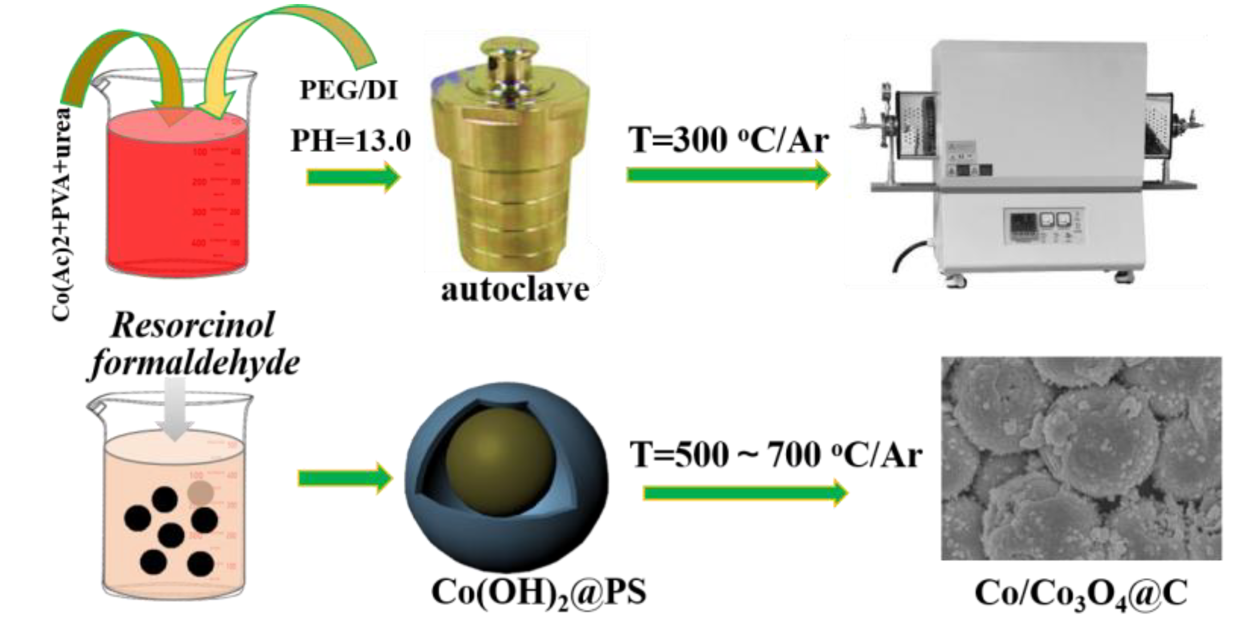
2.1. Preparation of Co3O4 Nanospheres
2.2. Synthesis of Co/Co3O4@C Hybrids
2.3. Characterization
3. Results and Discussion
4. Conclusions
Supplementary Materials
Author Contributions
Funding
Conflicts of Interest
References
- Xu, Y.; Yang, Y.; Yan, D.; Duan, H.; Zhao, G.; Liu, Y. Gradient Structure Design of Flexible Waterborne Polyurethane Conductive Films for Ultraefficient Electromagnetic Shielding with Low Reflection Characteristic. ACS Appl. Mater. Interfaces 2018, 10, 19143–19152. [Google Scholar] [CrossRef]
- Pastore, R.; Delfini, A.; Micheli, D.; Vricella, A.; Marchetti, M.; Santoni, F.; Piergentili, F. Carbon foam electromagnetic mm-wave absorption in reverberation chamber. Carbon 2019, 144, 63–71. [Google Scholar] [CrossRef]
- Lv, H.; Yang, Z.; Xu, H.B.; Wang, L.Y.; Wu, R.B. An electrical switch-driven flexible electromagnetic absorber. Adv. Funct. Mater. 2019, 30, 1907251. [Google Scholar] [CrossRef]
- Lou, Z.C.; Yaun, C.L.; Zhang, Y.; Li, Y.; Cai, J.B.; Yang, L.T.; Wang, W.K.; Han, H.; Zou, J. Synthesis of porous carbon matrix with inlaid Fe3C/Fe3O4 microparticles as an effective electromagnetic absorber from natural wood shavings. J. Alloys Compd. 2019, 775, 800–809. [Google Scholar] [CrossRef]
- Feng, A.; Hou, T.; Jia, Z. Synthesis of a hierarchical carbon fiber@cobalt ferrite@manganese dioxide composite and its application as a microwave absorber. RSC Adv. 2020, 10, 10501. [Google Scholar] [CrossRef]
- Zhou, X.F.; Jia, Z.R.; Kou, J.H.; Cao, H.J.; Liu, X.H. Construction of multiple electromagnetic loss mechanism for enhanced electromagnetic absorption performance of fish scale-derived biomass absorber. Compos. Part B-Eng. 2020, 192, 107980. [Google Scholar] [CrossRef]
- Lou, Z.; Li, R.; Wang, P.; Zhang, Y.; Chen, B.; Huang, C.; Wang, C.; Han, H.; Li, Y. Phenolic foam-derived magnetic carbon foams (MCFs) with tunable electromagnetic wave absorption behavior. Chem. Eng. J. 2019. [Google Scholar] [CrossRef]
- Zhang, Y.; Huang, Y.; Zhang, T.F.; Chang, H.C.; Xiao, P.S.; Chen, H.H.; Huang, Z.Y.; Chen, Y.S. Broadband and tunable high-performance microwave absorption of an ultralight and highly compressible graphene foam. Adv. Mater. 2015, 27, 2049–2053. [Google Scholar] [CrossRef]
- Lim, H.R.; Jung, S.J.; Hwang, T.Y.; Lee, J.M.; Kim, K.H.; Cho, H.B.; Choa, Y.H. Electromagnetic wave absorption properties of Fe/MgO composites synthesized by a simple ultrasonic spray pyrolysis method. Appl. Surf. Sci. 2019, 473, 1009–1013. [Google Scholar] [CrossRef]
- Lv, H.; Zhang, H.Q.; Zhao, J.; Ji, G.; Du, Y.W. Achieving excellent bandwidth absorption by a mirror growth process of magnetic porous polyhedron structures. Nano Res. 2016, 9, 1813–1822. [Google Scholar] [CrossRef]
- Lu, Y.Y.; Wang, Y.T.; Li, H.L.; Lin, Y.; Jiang, Z.Y.; Xie, Z.X.; Kuang, Q.; Zheng, L.S. MOF-derived porous Co/C nanocomposites with excellent electromagnetic wave absorption properties. ACS Appl. Mater. Interface 2015, 7, 13604–13611. [Google Scholar] [CrossRef] [PubMed]
- Wu, G.; Zhang, H.X.; Luo, X.X.; Yang, L.J. Investigation and optimization of Fe/ZnFe2O4 as a wide-band electromagnetic absorber. J. Colloid Interf. Sci. 2019, 536, 548–555. [Google Scholar] [CrossRef] [PubMed]
- Zhao, B.; Li, Y.; Liu, J.W.; Fan, L.; Gao, K.; Bai, Z.Y.; Liang, L.Y.; Gao, X.Q.; Zhang, R. Symmetrical polyhedron-bowl Co/CoO with hexagonal plate to forward electromagnetic wave absorption ability. CrystEngComm 2019, 5, 816–826. [Google Scholar] [CrossRef]
- Li, S.P.; Huang, Y.; Zhang, N.; Zong, M.; Liu, P.B. Synthesis of polypyrrole decorated FeCo@SiO2 as a high-performance electromagnetic absorption material. J. Alloys Compd. 2019, 774, 532–539. [Google Scholar] [CrossRef]
- Xu, Z.; Du, Y.C.; Liu, D.W.; Wang, Y.H.; Ma, W.J.; Wang, Y.; Xu, P.; Han, X.J. Pea-like Fe/Fe3C nanoparticles embedded in Nitrogen-doped carbon nanotubes with tunable dielectric/magnetic loss and efficient electromagnetic absorption. ACS Appl. Mater. Interfaces 2019, 11, 4268–4277. [Google Scholar] [CrossRef]
- Chen, C.; Zhen, S.; Zhang, B.S.; Zhou, Y.Y.; Li, S.M. Development of sulfide-doped graphene/Fe3O4 absorber with wide band electromagnetic absorption performance. J. Alloys Compd. 2019, 770, 90–97. [Google Scholar] [CrossRef]
- Huangfu, Y.M.; Liang, C.B.; Han, Y.X.; Qiu, H.; Song, P.; Wang, L.; Kong, J.; Gu, J.W. Fabrication and investigation on the Fe3O4/thermally annealed graphene aerogel/epoxy electromagnetic interference shielding nanocomposites. Compos. Sci. Technol. 2019, 169, 70–75. [Google Scholar] [CrossRef]
- Lv, H.L.; Guo, Y.H.; Wu, G.L.; Ji, G.B.; Zhao, Y.; Xu, Z.C.J. Interface polarization strategy to solve electromagnetic interference issue. ACS Appl. Mater. Interfaces. 2017, 9, 5660–5668. [Google Scholar] [CrossRef]
- Ma, J.R.; Shu, J.C.; Cao, W.Q.; Zhang, M.; Wang, X.X.; Yuan, J.; Cao, M.S. A green fabrication and variable temperature electromagnetic properties for thermal stable microwave absorption towards flower-like Co3O4@rGO/SiO2 composites. Compos. Part B-Eng. 2019, 166, 187–195. [Google Scholar] [CrossRef]
- Zhang, M.; Li, Z.J.; Wang, T.; Ding, S.Q.; Song, G.Y.; Zhao, J.; Meng, A.; Yu, H.Y.; Li, Q.D. Preparation and electromagnetic wave absorption performance of Fe3Si@SiC@SiO2 nanocomposites. Chem. Eng. J. 2019, 362, 619–627. [Google Scholar] [CrossRef]
- Lv, H.; Ji, G.; Liu, W.; Du, Y.W.Y. Achieving hierarchical hollow carbon@Fe@Fe3O4 nanospheres with superior microwave absorption properties and lightweight features. J. Mater. Chem. C 2015, 3, 10232–10241. [Google Scholar] [CrossRef]
- Liang, X.; Cheng, Y.; Zhang, H. Coin-like α-Fe2O3@CoFe2O4 core-shell composites with excellent electromagnetic absorption performance. ACS Appl. Mater. Interfaces. 2015, 7, 4744–4750. [Google Scholar]
- Yang, Z.; Ong, S.J.H.; Wei, C.; Liao, H.; Xi, S.B.; Du, Y.H. A flexible microwave shield with tunable frequency-transmission and electromagnetic compatibility. Adv. Funct. Mater. 2019, 29, 1900163. [Google Scholar]
- Yang, L.J.; Zhang, Y.; Liu, J.C.; Yang, Z.H. Multiple polarization effect of shell evolution on hierarchical hollow C@MnO2 composites and their wideband electromagnetic wave absorption properties. Chem. Eng. J. 2020, 392, 123666. [Google Scholar] [CrossRef]
- Zhang, H.X.; Jia, Z.; Feng, A.; Zhou, Z.H.; Zhang, C.H.; Wang, K.K.; Liu, N. Enhanced microwave absorption performance of sulfur-doped hollow carbon microspheres with mesoporous shell as broadband absorber. Compos. Commun. 2020, 19, 42–50. [Google Scholar] [CrossRef]
- Lv, H.; Yang, Z.; Wang, P.L.Y.; Ji, G.; Song, J.Z.; Zheng, L.R. A voltage-boosting strategy enabling a low-frequency, flexible electromagnetic wave absorption device. Adv. Mater. 2018, 30, 1706343. [Google Scholar] [CrossRef]
- Kong, L.; Yin, X.W.; Xu, H.L.; Yuan, X.Y.; Wang, T.; Xu, Z.W.; Huang, J.F.; Yang, R.; Fan, H. Powerful absorbing and lightweight electromagnetic shielding CNTs/RGO composite. Carbon 2019, 145, 61–66. [Google Scholar] [CrossRef]
- Wu, G.L.; Cheng, Y.H.; Yang, Z.H.; Jia, Z.R.; Wu, H.J.; Yang, L.J.; Li, H.L.; Guo, P.Z. Design of carbon sphere/magnetic quantum dots with tunable phase compositions and boost loss behavior. Chem. Eng. J. 2018, 333, 519–528. [Google Scholar] [CrossRef]
- Li, W.C.; Cai, H.W.; Kang, Y.; Ying, Y.; Yu, J.; Zheng, J.W.; Qiao, L.; Jiang, Y.; Che, S.L. High permeability and low loss bioinspired soft magnetic composites with nacre-like structure for high frequency applications. Acta Mater. 2019, 167, 267–274. [Google Scholar] [CrossRef]
- Li, J.; Zhao, X.L.; Liu, J.P.; Zhang, L.; Yang, C.H. Ultralight carbon-based Co(OH)2-Co3O4/nanocomposite with superior performance in wave absorption. J. Alloys Compd. 2019, 777, 954–962. [Google Scholar] [CrossRef]
- Zhao, B.; Guo, X.Q.; Zhao, W.Y.; Deng, J.S.; Fan, B.B.; Shao, G.; Bai, Z.Y.; Zhang, R. Facile synthesis of yolk-shell Ni@void@SnO2(Ni3Sn2) ternary composites via galvanic replacement/Kirkendall effect and their enhanced microwave absorption properties. Nano Res. 2017, 10, 331–343. [Google Scholar] [CrossRef]
- Wu, N.N.; Qiao, J.; Liu, J.R.; Du, W.J.; Xu, D.M.; Liu, W. Strengthened electromagnetic absorption performance derived from synergistic effect of carbon nanotube hybrid with Co@C beads. Adv. Compos. Mater. 2018, 1, 149–159. [Google Scholar] [CrossRef]
- Zhao, B.; Deng, J.S.; Liang, L.Y.; Zuo, C.Y.X.; Bai, Z.Y.; Guo, X.Q.; Zhang, R. Lightweight porous Co3O4 and Co/CoO nanofibers with tunable impedance match configuration-dependent microwave absorption properties. CrystEngComm 2017, 41, 6095–6106. [Google Scholar] [CrossRef]
- Zhu, C.L.; Zhang, S.; Sun, Y.; Chen, Y.J. Incorporation of CoO@Co yolk-shell nanoparticles and ZnO nanoparticles with graphene sheets as lightweight and high-performance electromagnetic wave absorbing material. J. Alloys Compd. 2017, 711, 552–559. [Google Scholar] [CrossRef]
- Zhang, X.; Yan, F.; Zhang, S.; Yuan, H.R.; Zhu, C.L.; Zhang, X.T.; Chen, Y.J. Hollow N-doped carbon polyhedron containing CoNi alloy nanoparticles embedded within few-layer N-doped graphene as high-performance electromagnetic wave absorbing material. ACS Appl. Mater. Interfaces 2018, 10, 24920–24929. [Google Scholar] [CrossRef] [PubMed]
- Liao, Q.; He, M.; Zhou, Y.M.; Nie, S.X.; Wang, Y.J.; Hu, S.C.; Yang, H.Y.; Li, J.F.; Tong, Y. Highly cuboid-shaped heterobimetallic metal-organic frameworks derived from porous Co/ZnO/C microrods with improved electromagnetic wave absorption capabilities. ACS Appl. Mater. Interfaces 2018, 10, 29136–29144. [Google Scholar] [CrossRef] [PubMed]
- Li, Y.; Li, S.; Zhang, T.; Shi, L.L.; Liu, S.T.; Zhao, Y. 3D hierarchical Co3O4/reduced graphene oxide/melamine derived carbon foam as a comprehensive microwave absorbing material. J. Alloys Compd. 2019, 792, 424–431. [Google Scholar] [CrossRef]
- Jia, H.X.; Xing, H.L.; Ji, X.L.; Gao, S.T. Synergistic effect of hexagonal flake Co3O4@PANI core-shell composites with excellent microwave absorbing properties. J. Mater. Sci. Mater. Electron. 2019, 30, 3386–3395. [Google Scholar] [CrossRef]
- Liang, X.H.; Ji, G.B.; Zhang, H.Q.; Du, Y.W. Porous three-dimensional flower-like Co/CoO and excellent electromagnetic absorption properties. ACS Appl. Mater. Interfaces 2015, 7, 9776–9783. [Google Scholar]
- Liu, H.H.; Li, Y.J.; Yuan, M.W.; Sun, G.B.; Li, H.F.; Ma, S.M.; Liao, Q.L.; Zhang, Y. In-situ preparation of cobalt nanoparticles decorated in N-doped carbon nanofibers as excellent electromagnetic wave absorbers. ACS Appl. Mater. Interfaces 2018, 10, 22591–22601. [Google Scholar] [CrossRef]
- Dong, S.; Zhang, X.H.; Hu, P.T.; Zhang, W.Z.; Han, J.C.; Hu, P. Biomass-derived carbon and polypyrrole addition on SiC whiskers for enhancement of electromagnetic wave absorption. Carbon 2019, 359, 882–893. [Google Scholar] [CrossRef]
- Liu, L.; He, N.; Wu, T.; Hu, P.B.; Tong, G.X. Co/C/Fe/C hierarchical flowers with strawberry-like surface as surface plasmon for enhanced permittivity, permeability, and microwave absorption properties. Chem. Eng. J. 2019, 355, 103–108. [Google Scholar] [CrossRef]
- Yang, M.L.; Yuan, Y.; Yin, W.L.; Peng, Q.Y.; Li, J.J.; He, X.D. Co/CoO@C nanocomposites with a hierarchical bowknot-like nanostructure for high-performance broadband electromagnetic wave absorption. Appl. Surf. Sci. 2019, 469, 607–616. [Google Scholar] [CrossRef]
- Wu, G.; Jia, Z.; Zhou, X.F.; Nie, G. Interlayer controlled of hierarchical MWCNTs@C@FexOy cross-linked composite with wideband electromagnetic absorption performance. Compos. Part A-Appl. Sci. Manuf. 2020, 128, 105687. [Google Scholar] [CrossRef]
- Lv, H.; Zhang, H.; Ji, G. Interface strategy to achieve tunable high frequency attenuation. ACS Appl. Mater. Interfaces 2016, 8, 6295–6538. [Google Scholar] [CrossRef] [PubMed]
- Sheng, A.; Ren, W.; Yang, Y.; Yan, D.X.; Duan, H.; Zhao, G.; Liu, Y.; Li, Z.M. Multilayer WPU conductive composites with controllable electro-magnetic gradient for absorption-dominated electromagnetic interference shielding. Compos. Part A 2020, 129, 105692. [Google Scholar] [CrossRef]
- Liu, X.F.; Nie, X.Y.; Yu, R.H.; Feng, H.B. Design of dual-frequency electromagnetic wave absorption by interface modulation strategy. Chem. Eng. J. 2018, 334, 153–161. [Google Scholar] [CrossRef]
- Guo, Y.H.; Yang, Z.; Zhao, Y. A brief introduction to the fabrication and synthesis of graphene based composites for the realization of electromagnetic absorbing materials. J. Mater. Chem. C 2017, 3, 491–512. [Google Scholar]
- Li, J.S.; Xie, Y.Z.; Lu, W.B.; Chou, T.W. Flexible electromagnetic wave absorbing composite based on 3D rGO-CNT-Fe3O4 ternary films. Carbon 2018, 129, 76–84. [Google Scholar] [CrossRef]
- Jia, Z.; Kou, K.; Yin, S.; Feng, A. Magnetic Fe nanoparticle to decorate N dotted C as an exceptionally absorption-dominate electromagnetic shielding material. Compos. Part B-Eng. 2020, 189, 107895. [Google Scholar] [CrossRef]


| Samples | RLmin (dB) | Effective Absorption Region (GHz) | Thickness (mm) | Ref. |
|---|---|---|---|---|
| Co@C | ~−10 | <3.0 | 1.5 | [32] |
| Porous carbon | −23.8 | ~3.8 | 2.0 | [33] |
| CoO@Co/ZnO/graphene | −51.5 | 4.7 | 2.6 | [34] |
| CoNi@C | −24.03 | 4.32 | 2.5 | [35] |
| Co/ZnO/C | −52.6 | 4.9 | 3.0 | [36] |
| Co3O4/graphene | −31.88 | 3.4 | 2.0 | [37] |
| Co3O4@PANI | −37.39 | ~4.2 | 4.0 | [38] |
| Co/CoO | −50 dB | 4.2 | 2.0 | [39] |
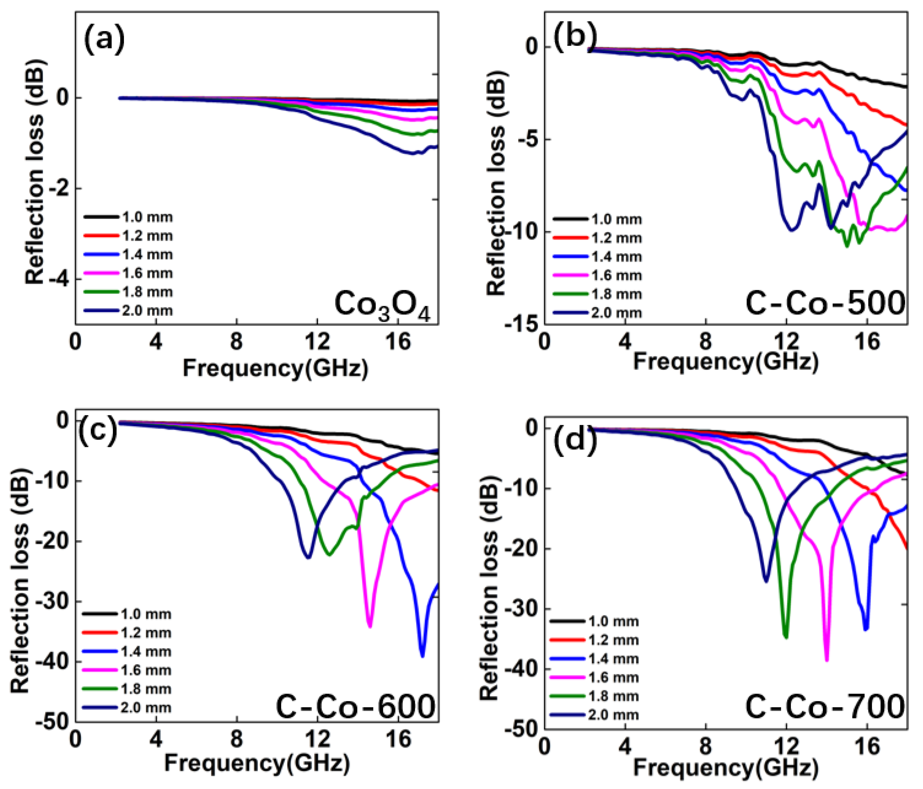
| C-Co-600 | −39.4 dB | 4.3 | 1.4 mm | This work |
© 2020 by the authors. Licensee MDPI, Basel, Switzerland. This article is an open access article distributed under the terms and conditions of the Creative Commons Attribution (CC BY) license (http://creativecommons.org/licenses/by/4.0/).
Share and Cite
Bao, W.; Chen, C.; Si, Z. An Easy Method of Synthesis CoxOy@C Composite with Enhanced Microwave Absorption Performance. Nanomaterials 2020, 10, 902. https://doi.org/10.3390/nano10050902
Bao W, Chen C, Si Z. An Easy Method of Synthesis CoxOy@C Composite with Enhanced Microwave Absorption Performance. Nanomaterials. 2020; 10(5):902. https://doi.org/10.3390/nano10050902
Chicago/Turabian StyleBao, Wenli, Cong Chen, and Zhenjun Si. 2020. "An Easy Method of Synthesis CoxOy@C Composite with Enhanced Microwave Absorption Performance" Nanomaterials 10, no. 5: 902. https://doi.org/10.3390/nano10050902