
Combined Porous-Monolithic TiNi Materials Surface-Modified with Electron Beam for New-Generation Rib Endoprostheses
 ,
,  , , , , , and
Abstract
:1. Introduction
2. Materials and Methods
2.1. Material Preparation
2.2. Sample Characterization
2.3. Electrochemical Corrosion Study
2.4. Biocompatibility and Cytotoxicity Experiments
2.4.1. Hemolysis Study
2.4.2. Cytotoxicity Study
2.4.3. Cell Viability Study
2.4.4. Cell Growth Study
3. Results and Discussion
3.1. Structure and Composition of Combined Monolithic-Porous Material
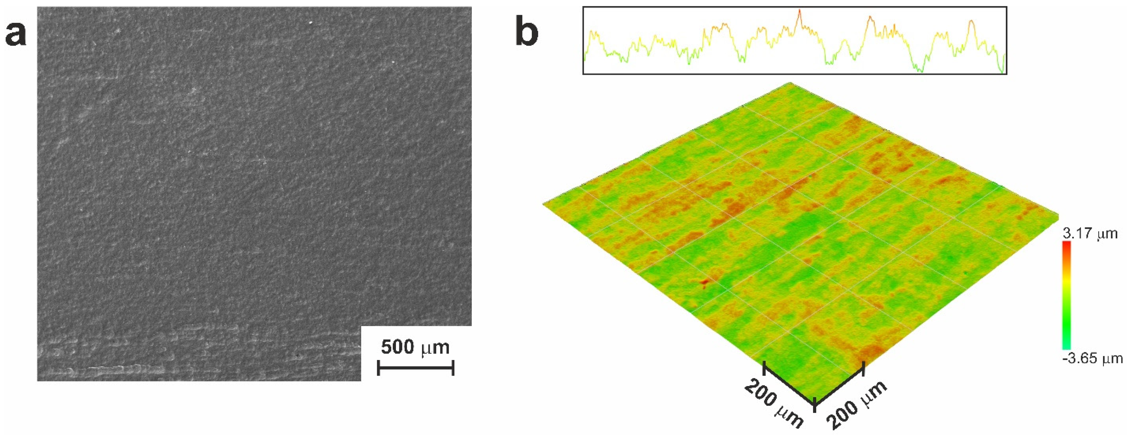
3.1.1. Monolithic Part of the Material
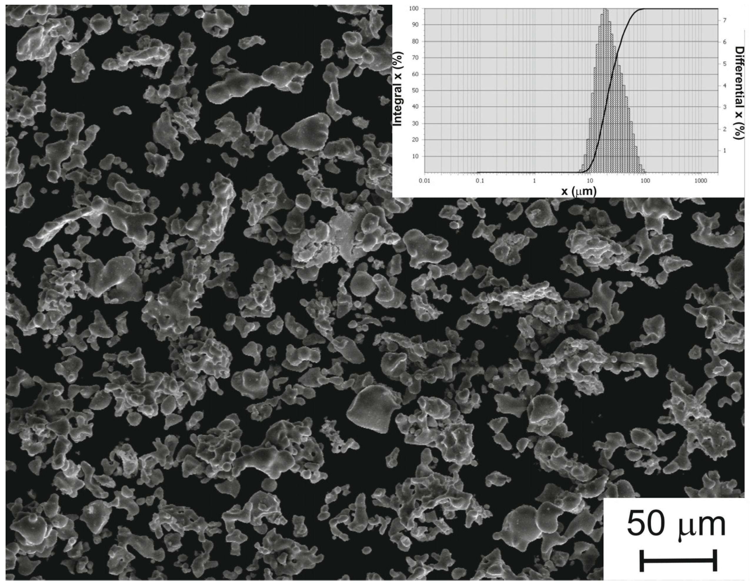
3.1.2. TiNi Powder Used in the Study
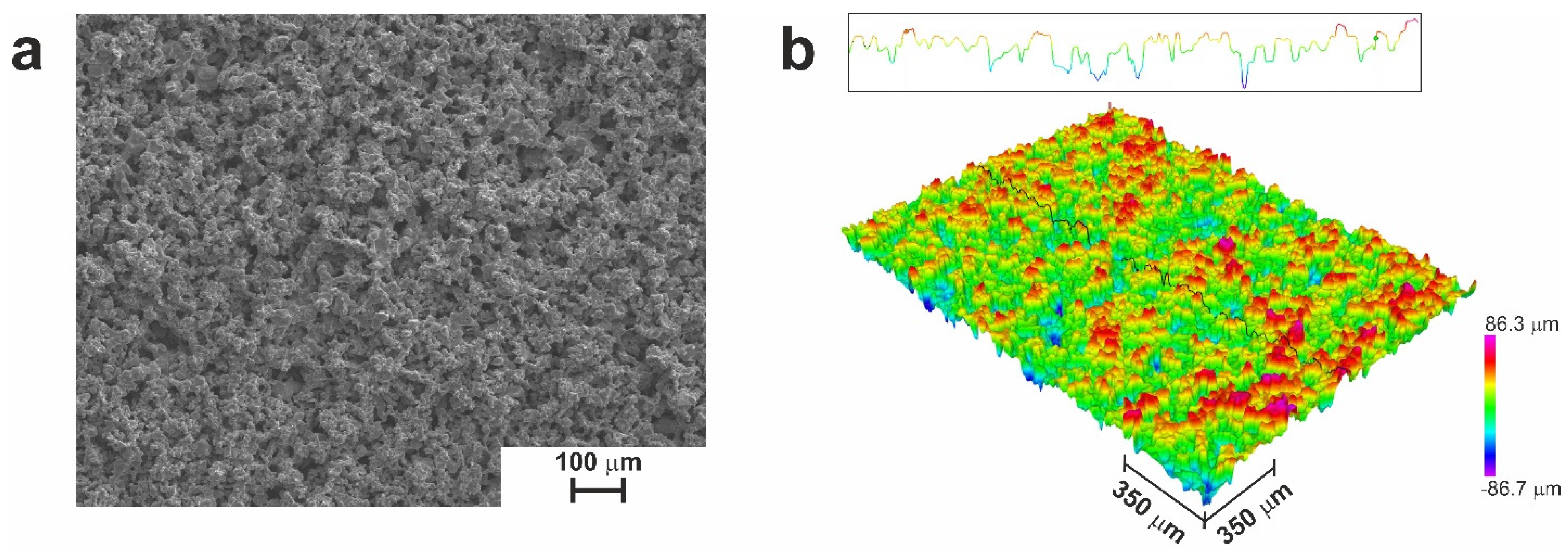
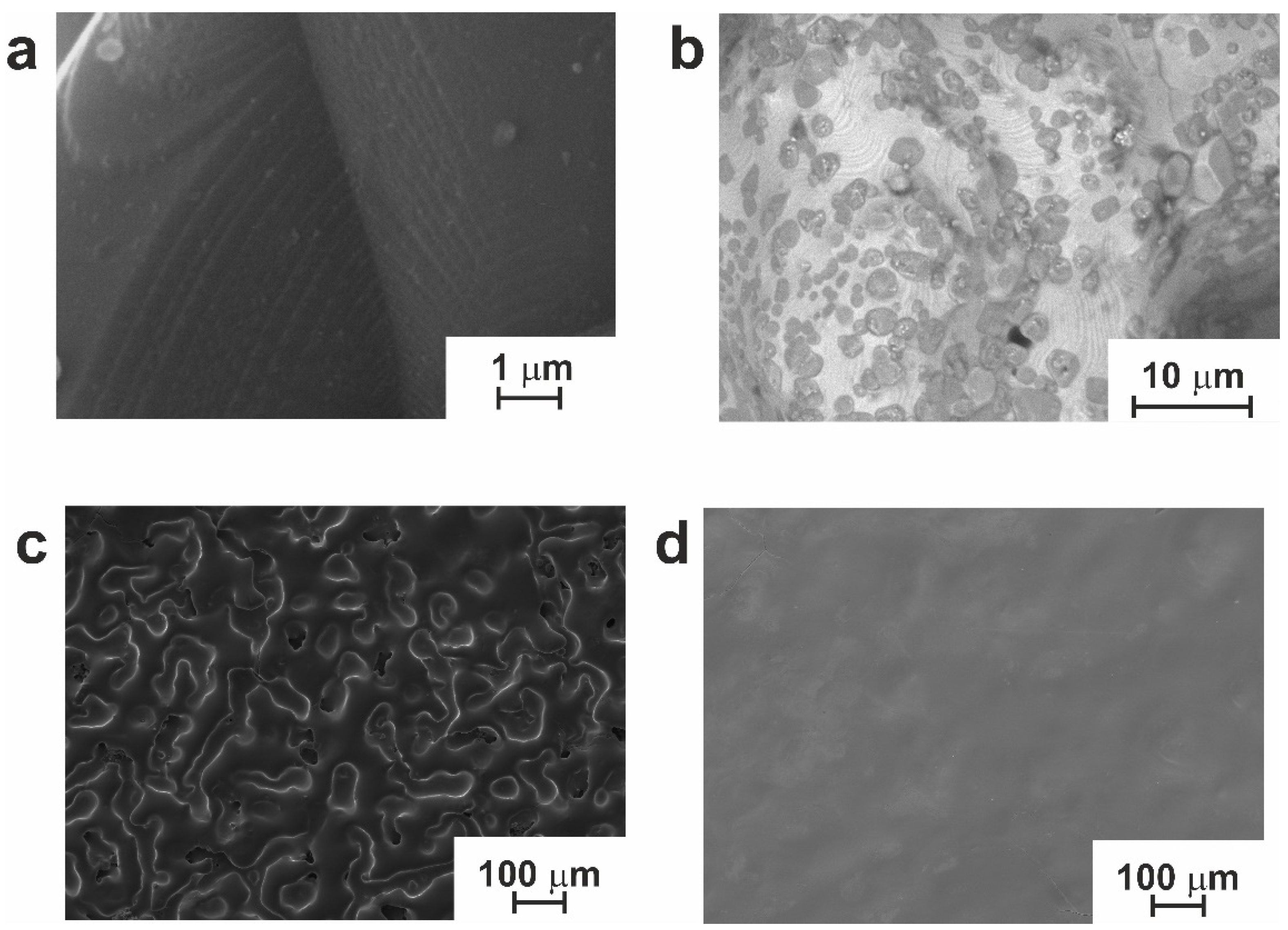
3.1.3. Resultant Structure of TiNi Powder and Monolithic Parts and Their Subsequent Treatment
3.1.4. Composition of Obtained Materials
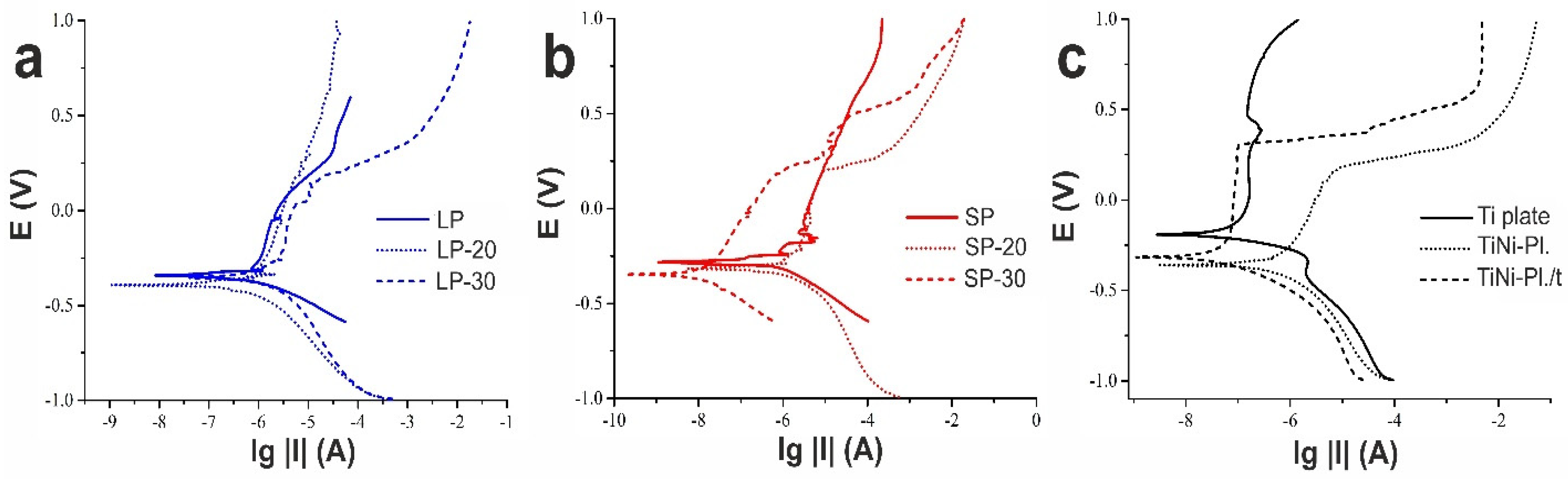
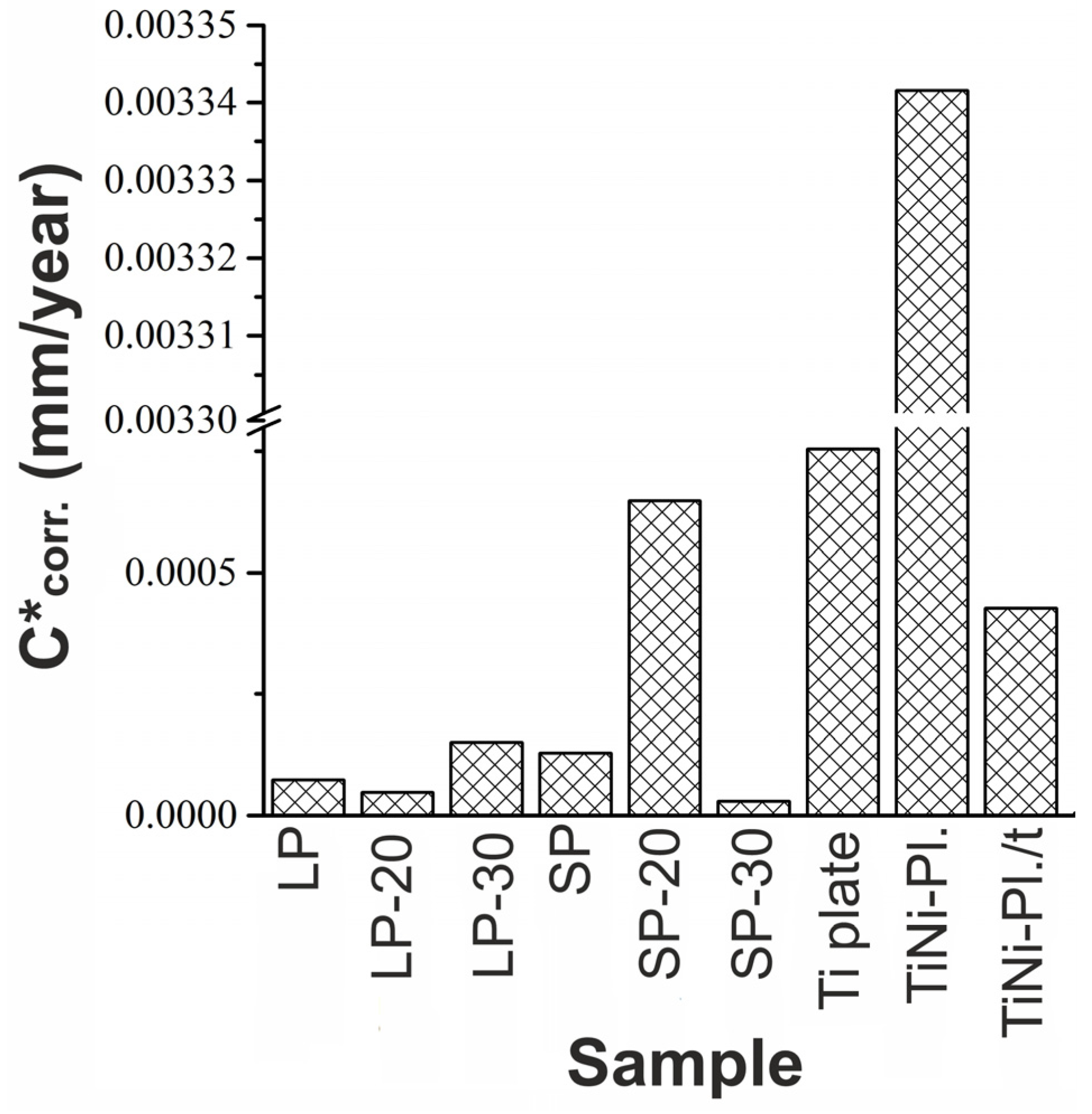
3.2. Corrosion Study of the Materials
3.3. Biomedical Characterization
3.3.1. Hemolysis and Cytotoxicity Study
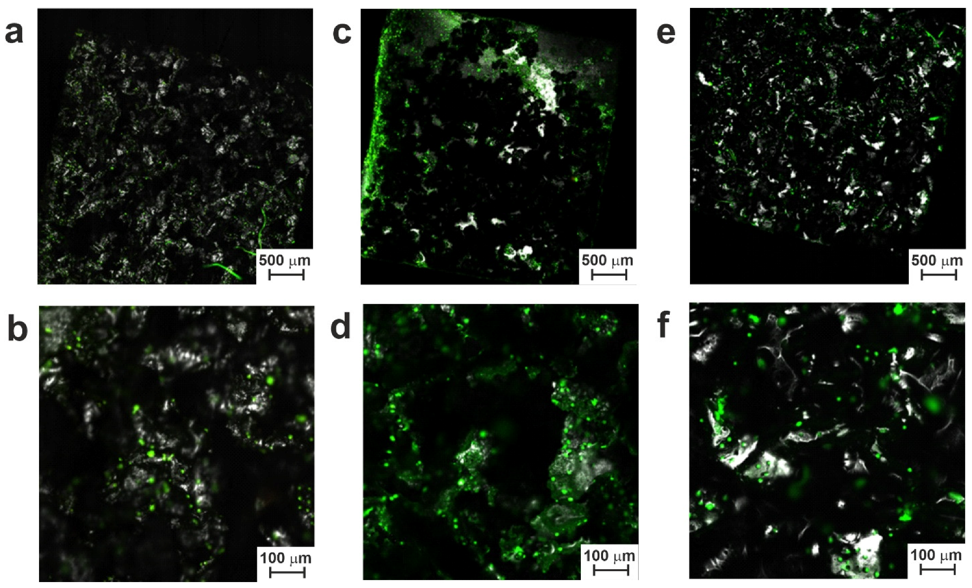
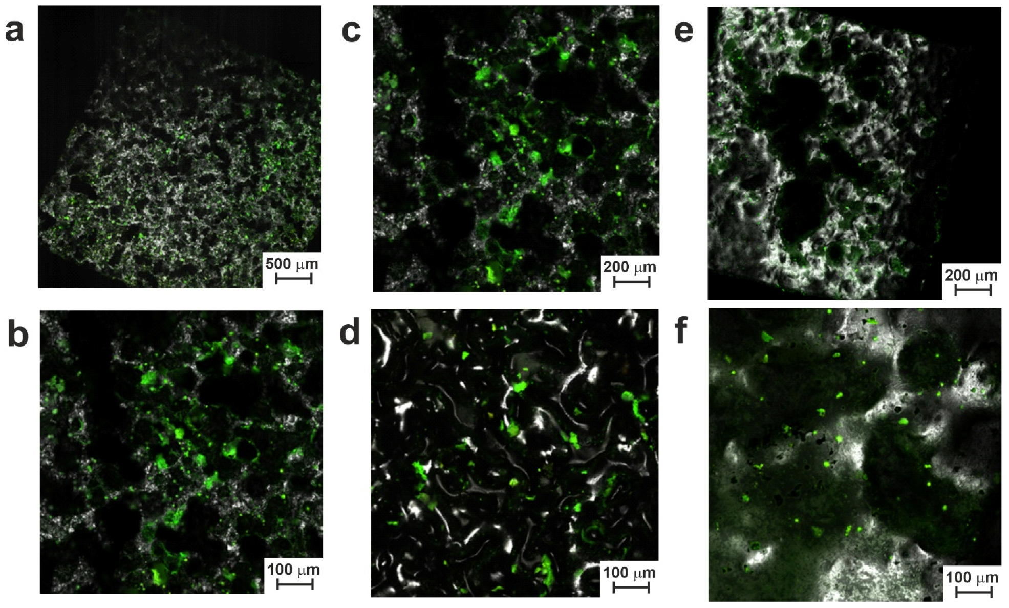
3.3.2. Cell Growth Experiments
4. Conclusions
Supplementary Materials
Author Contributions
Funding
Institutional Review Board Statement
Informed Consent Statement
Data Availability Statement
Acknowledgments
Conflicts of Interest
References
- Buehler, W.J.; Gilfrich, J.W.; Wiley, R.C. Effect of low-temperature phase changes on the mechanical properties of alloys near composition TiNi. J. Appl. Phys. 1963, 34, 1475–1477. [Google Scholar] [CrossRef]
- Otsuka, K.; Ren, X. Physical metallurgy of Ti-Ni based shape memory alloys. Prog. Mater Sci. 2005, 50, 511–678. [Google Scholar] [CrossRef]
- Saburi, T. Ti-Ni shape memory alloys. In Shape Memory Materials; Otsuka, K., Waymann, C.M., Eds.; Cambridge University Press: Cambridge, UK, 1999; pp. 49–96. [Google Scholar]
- Parvizi, S.; Hashemi, S.M.; Asgarinia, F.; Nematollahi, M.; Elahinia, M. Effective parameters on the final properties of NiTi-based alloys manufactured by powder metallurgy methods: A review. Prog. Mater. Sci. 2021, 117, 100739. [Google Scholar] [CrossRef]
- Saber, O.; Ansari, S.A.; Alshoaibi, A. Development of Ti/Ni nanolayered structures to be a new candidate for energy storage applications. Appl. Sci. 2020, 10, 6935. [Google Scholar] [CrossRef]
- Jani, J.M.; Leary, M.; Subic, A.; Gibson, M.A. A review of shape memory alloy research, applications and opportunities. Mater. Des. 2014, 56, 1078–1113. [Google Scholar] [CrossRef]
- Carpegna, G.; Alovisi, M.; Paolino, D.S.; Marchetti, A.; Gibello, U.; Scotti, N.; Pasqualini, D.; Scattina, A.; Chiandussi, G.; Berutti, E. Evaluation of pressure distribution against root canal walls of NiTi rotary instruments by finite element analysis. Appl. Sci. 2020, 10, 2981. [Google Scholar] [CrossRef]
- Sachdeva, R.C.L.; Miyazaki, S. Nitinol as a biomedical material. Encycl. Mater. Sci. Technol. 2001, 6155–6160. [Google Scholar] [CrossRef]
- Wadood, A. Brief overview on nitinol as biomaterial. Adv. Mater. Sci. Eng. 2016, 2016, 4173138. [Google Scholar] [CrossRef]
- Dagna, A.; Gastaldo, G.; Beltrami, R.; Poggio, C. Debris evaluation after root canal shaping with rotating and reciprocating single-file systems. J. Funct. Biomater. 2016, 7, 28. [Google Scholar] [CrossRef]
- Poggio, C.; Dagna, A.; Chiesa, M.; Beltrami, R.; Bianchi, S. Cleaning effectiveness of three NiTi rotary instruments: A focus on biomaterial properties. J. Funct. Biomater. 2015, 6, 66–76. [Google Scholar] [CrossRef]
- Stoeckel, D.; Pelton, A.; Duerig, T. Self-expanding nitinol stents for the treatment of vascular disease. Shape Mem. Alloy. Biomed. Appl. 2009, 237–256. [Google Scholar] [CrossRef]
- Pelton, A.R.; Schroeder, V.; Mitchell, M.R.; Gong, X.Y.; Barney, M.; Robertson, S.W. Fatigue and durability of nitinol stents. J. Mech. Behav. Biomed. Mater. 2008, 1, 153–164. [Google Scholar] [CrossRef] [PubMed]
- Early, M.; Kelly, D.J. The consequences of the mechanical environment of peripheral arteries for NiTi stenting. Med. Biol. Eng. Comput. 2011, 49, 1279–1288. [Google Scholar] [CrossRef] [PubMed]
- Dordoni, E.; Meoli, A.; Wu, W.; Dubini, G.; Migliavacca, F.; Pennati, G.; Petrini, L. Fatigue behaviour of nitinol peripheral stents: The role of plaque shape studied with computational structural analyses. Med. Eng. Phys. 2014, 36, 842–849. [Google Scholar] [CrossRef] [PubMed]
- Wawrzynski, J.; Gil, J.A.; Goodman, A.D.; Waryasz, G.R. Hypersensitivity to orthopedic implants: A review of the literature. Rheumatol. Ther. 2017, 4, 45–56. [Google Scholar] [CrossRef] [PubMed]
- Majumdar, T.; Eisenstein, N.; Frith, J.E.; Cox, S.C.; Birbilis, N. Additive manufacturing of titanium alloys for orthopedic applications: A materials science viewpoint. Adv. Eng. Mater. 2018, 20, 1800172. [Google Scholar] [CrossRef]
- Anikeev, S.G.; Kaftaranova, M.I.; Hodorenko, V.N.; Ivanov, S.D.; Artyukhova, N.V.; Shabalina, A.V.; Kulinich, S.A.; Slizovsky, G.V.; Mokshin, A.V.; Gunther, V.E. TiNi-based material with shape-memory effect for surgical treatment of diseases of small intestine in newborn and young children. J. Funct. Biomater. 2023, 14, 155. [Google Scholar] [CrossRef]
- Iliushenov, V.N.; Iliushenov, A.V.; Iliushenov, S.V.; Anikeev, S.G.; Marchenko, E.S.; Baigonakova, G.A.; Gunther, V.E. Surgical treatment of fractures of long tubular bones of elderly and old-aged people with the usage of shape memory implants. KnE Mater. Sci. 2017, 2, 227–235. [Google Scholar] [CrossRef]
- Shtin, V.I.; Novikov, V.A.; Gunther, V.E.; Choinzonov, E.I.; Ryabova, A.I.; Sirkashev, V.A.; Surkova, P.V.; Yasenchuk, Y.F.; Anikeev, S.G.; Vasilev, R.V. Current aspects in reconstructive surgery for nasal cavity and paranasal sinus cancer. KnE Mater. Sci. 2017, 2, 327–333. [Google Scholar] [CrossRef]
- Steblyuk, A.N.; Gunther, V.E.; Bodnia, V.N.; Avakimyan, R.A.; Tserkovnaya, A.A. A new method for non-invasive surgery in ophthalmology. KnE Mater. Sci. 2017, 2, 261–266. [Google Scholar] [CrossRef]
- Gunther, S.V.; Anikeev, S.G.; Ji-soon, K.; Monogenov, A.N.; Gunther, V.E. The technology of the manufacturing thin wire of TiNi-based alloys by using infrared radiation. KnE Mater. Sci. 2017, 2, 88–97. [Google Scholar] [CrossRef]
- Nikoomanzari, E.; Karbasi, M.; Melo, W.C.; Moris, H.; Babaei, K.; Giannakis, S.; Fattah-alhosseini, A. impressive strides in antibacterial performance amelioration of Ti-based implants via plasma electrolytic oxidation (PEO): A review of the recent advancements. Chem. Eng. J. 2022, 441, 136003. [Google Scholar] [CrossRef]
- Jang, S.R.; Suh, I.W.; Heng, L. Nanoscale polishing technique of biomedical grade NiTi wire by advanced maf process: Relationship between surface roughness and bacterial adhesion. J. Funct. Biomater. 2023, 14, 177. [Google Scholar] [CrossRef] [PubMed]
- Benčina, M.; Mavrič, T.; Junkar, I.; Bajt, A.; Krajnović, A.; Lakota, K.; Žigon, P.; Sodin-Šemrl, S.; Kralj-Iglič, V.; Iglič, A. The importance of antibacterial surfaces in biomedical applications. Adv. Biomembr. Lipid Self-Assem. 2018, 28, 115–165. [Google Scholar] [CrossRef]
- Sysolyatin, P.G.; Gunther, V.E.; Sysolyatin, S.P.; Mirgazizov, M.Z.; Radkevich, A.A.; Olesova, V.N.; Khodorenko, V.N.; Dyuryagin, N.M.; Melnik, D.D.; Tazin, I.D.; et al. Medical materials with shape memory. In Shape Memory Implants in Maxillofacial Surgery, 4th ed.; NPP «MIC»: Tomsk, Russia, 2012; p. 384. (In Russian) [Google Scholar]
- Dambaev, G.T.; Topolnitsky, E.B.; Gunter, V.E.; Shefer, N.A.; Khodorenko, V.N.; Sokolovich, E.G.; Fomina, T.I.; Kapitanov, V.A.; Zheravin, A.A.; Gunter, S.V.; et al. Shape Memory Implants in Thoracic Surgery; NPP «MIC»: Tomsk, Russia, 2016; p. 232. (In Russian) [Google Scholar]
- Mirgazizov, M.Z.; Gunter, V.E.; Galonsky, V.G.; Olesova, V.N.; Radkevich, A.A.; Khafizov, R.G.; Mirgazizov, R.M.; Yudin, P.S.; Starosvetsky, S.I.; Zvigintsev, M.A. et al. Materials and Implants with Shape Memory in Dentistry, 5th ed.; NPP «MIC»: Tomsk, Russia, 2011; p. 220. (In Russian) [Google Scholar]
- Topolnitskiy, E.; Chekalkin, T.; Marchenko, E.; Yasenchuk, Y.; Kang, S.B.; Kang, J.H.; Obrosov, A. Evaluation of clinical performance of TiNi-based implants used in chest wall repair after resection for malignant tumors. J. Funct. Biomater. 2021, 12, 60. [Google Scholar] [CrossRef]
- Topolnitskiy, E.; Chekalkin, T.; Marchenko, E.; Yasenchuk, Y. Repair of huge thoracic defect combined with hernia after multimodality treatment of breast cancer. Respir. Med. Case Rep. 2021, 34, 101558. [Google Scholar] [CrossRef]
- Zheravin, A.A.; Gyunter, V.E.; Anisenya, I.I.; Garbukov, E.Y.; Zhamgaryan, G.S.; Bogoutdinova, A.V. Reconstruction of the chest wall using titanium nickelid for cancer patients. Sib. J. Oncol. 2015, 1, 31–37. (In Russian) [Google Scholar]
- Choinzonov, E.L.; Gunter, V.E.; Mukhamedov, M.R. Medical materials with shape memory. In Shape Memory Implants in Oncology, 13th ed.; NPP «MIC»: Tomsk, Russia, 2012; p. 336. (In Russian) [Google Scholar]
- Scientific Electronic Library Elibrary.Ru. Available online: https://www.elibrary.ru/item.asp?id=49994737 (accessed on 21 April 2023). (In Russian).
- Anikeev, S.; Yakovlev, E.; Artyukhova, N.; Mamazakirov, O.; Kaftaranova, M.; Promakhov, V. Production of two-dimensional porous TiNi-based powder material by diffusion sintering and electron-beam processing. In Proceedings of the 7th International Congress on Energy Fluxes and Radiation Effects (EFRE), Tomsk, Russia, 14–26 September 2020; pp. 1240–1243. [Google Scholar] [CrossRef]
- Anikeev, S.G.; Artyukhova, N.V.; Kaftaranova, M.I.; Khodorenko, V.N.; Yakovlev, E.V.; Markov, A.B.; Promakhov, V.V.; Mamazakirov, O.R. The influence of electron-beam treatment on the structure of a TiNi powder alloy obtained by calcium-hydride reduction. J. Surf. Investig. 2021, 15, 1067–1071. [Google Scholar] [CrossRef]
- Anikeev, S.G.; Shabalina, A.V.; Kulinich, S.A.; Artyukhova, N.V.; Korsakova, D.R.; Yakovlev, E.V.; Vlasov, V.A.; Kokorev, O.V.; Hodorenko, V.N. Preparation and electron-beam surface modification of novel TiNi material for medical applications. Appl. Sci. 2021, 11, 4372. [Google Scholar] [CrossRef]
- Anikeev, S.G.; Garin, A.S.; Artyukhova, N.V.; Khodorenko, V.N.; Gunther, V.E. Structural and morphological features of TiNi-based powder manufactured by the method of hybrid-calcium reduction. Russ. Phys. J. 2018, 61, 749–756. [Google Scholar] [CrossRef]
- Kasimtsev, A.V.; Markova, G.V.; Shuitsev, A.V.; Levinskii, Y.V.; Sviridova, T.A.; Alpatov, A.V. Change in structure during consolidation of calcium hydride powders of TiNi intermetallic. Metallurgist 2015, 58, 1038–1045. [Google Scholar] [CrossRef]
- Kasimtsev, A.V.; Markova, G.V.; Volodko, S.S.; Yudin, S.N.; Karpov, B.V.; Alimov, I.A. Powder titanium nickelide: Technology and properties. Russ. Metall. 2020, 11, 1267–1273. [Google Scholar] [CrossRef]
- Abdul’menova, E.V.; Kul’kov, S.N. Ti-Ni powder structure after mechanical activation and interaction with hydrogen. Russ. Phys. J. 2019, 62, 1455–1460. [Google Scholar] [CrossRef]
- Abdulmenova, E.V.; Buyakova, S.P.; Kulkov, S.N. Electrochemical hydrogenation of Ti–Ni powder mechanochemically alloyed with titanium. Intermetallics 2022, 151, 107739. [Google Scholar] [CrossRef]
- Markov, A.B.; Mikov, A.V.; Ozur, G.E.; Padei, A.G. A PÈTM-CP facility for the surface alloying. Instrum. Exp. Tech. 2011, 54, 862–866. [Google Scholar] [CrossRef]
- Frolov, Y.G. Course of Colloidal Chemistry. Surface Phenomena and Disperse Systems: Chemistry; Metallyrgy: Moscow, Russia, 1988; p. 464. (In Russian) [Google Scholar]
- Rotshtein, V.P.; Shulov, V.A. Surface modification and alloying of aluminum and titanium alloys with low-energy, high-current electron beams. J. Metall. 2011, 2011, 1–15. [Google Scholar] [CrossRef]
- Meisner, L.L.; Markov, A.B.; Proskurovsky, D.I.; Rotshtein, V.P.; Ozur, G.E.; Meisner, S.N.; Yakovlev, E.V.; Poletika, T.M.; Girsova, S.L.; Semin, V.O. Effect of inclusions on cratering behavior in TiNi shape memory alloys irradiated with a low-energy, high-current electron beam. Surf. Coatings Technol. 2016, 302, 495–506. [Google Scholar] [CrossRef]
- Meisner, L.L.; Markov, A.B.; Rotshtein, V.P.; Ozur, G.E.; Meisner, S.N.; Yakovlev, E.V.; Gudimova, E.Y. Formation of microcraters and hierarchically-organized surface structures in TiNi shape memory alloy irradiated with a low-energy, high-current electron beam. AIP Conf. Proc. 2015, 1683, 020145. [Google Scholar] [CrossRef]
- Zhang, K.M.; Zou, J.X.; Grosdidier, T.; Gey, N.; Weber, S.; Yang, D.Z.; Dong, C. Mechanisms of structural evolutions associated with the high current pulsed electron beam treatment of a NiTi shape memory alloy. J. Vac. Sci. Technol. A Vac. Surf. Film 2007, 25, 28–36. [Google Scholar] [CrossRef]
- Meisner, L.L.; Semin, V.O.; Mironov, Y.P.; Meisner, S.N.; D’yachenko, F.A. Cross-sectional analysis of the graded microstructure and residual stress distribution in a TiNi alloy treated with low energy high-current pulsed electron beam. Mater. Today Commun. 2018, 17, 169–179. [Google Scholar] [CrossRef]
- Meisner, L.L.; Lotkov, A.I.; Mironov, Y.P.; Neyman, A.A. Evolution of structural-phase states in TiNi surface layers synthesized by electron beam treatment. J. Nanotechnol. 2010, 2010, 605362. [Google Scholar] [CrossRef]
- Lippi, G.; Plebani, M.; Favaloro, E.J. Interference in coagulation testing: Focus on spurious hemolysis, icterus, and lipemia. Semin. Thromb Hemost. 2013, 39, 258–266. [Google Scholar] [CrossRef] [PubMed]
- Lippi, G.; Cervellin, G.; Favaloro, E.J.; Plebani, M. Management of hemolyzed specimens. Lab. Serv. 2017, 6, 38–46. (In Russian) [Google Scholar] [CrossRef]
- Shayan, M.; Jankowitz, B.T.; Shridhar, P.; Chun, Y. Use of micropatterned thin film nitinol in carotid stents to augment embolic protection. J. Funct. Biomater. 2016, 7, 34. [Google Scholar] [CrossRef] [PubMed]
- Biela, S.A.; Su, Y.; Spatz, J.P.; Kemkemer, R. Different sensitivity of human endothelial cells, smooth muscle cells and fibroblasts to topography in the nano–Micro range. Acta Biomater. 2009, 5, 2460–2466. [Google Scholar] [CrossRef] [PubMed]
- Vandrangi, P.; Gott, S.C.; Kozaka, R.; Rodgers, V.G.J.; Rao, M.P. Comparative endothelial cell response on topographically patterned titanium and silicon substrates with micrometer to sub-micrometer feature sizes. PLoS ONE 2014, 9, 111465. [Google Scholar] [CrossRef]
- Aubin, H.; Nichol, J.W.; Hutson, C.B.; Bae, H.; Sieminski, A.L.; Cropek, D.M.; Akhyari, P.; Khademhosseini, A. Directed 3D cell alignment and elongation in microengineered hydrogels. Biomaterials 2010, 31, 6941–6951. [Google Scholar] [CrossRef]
- Shen, Y.; Wang, G.; Chen, L.; Li, H.; Yu, P.; Bai, M.; Zhang, Q.; Lee, J.; Yu, Q. Investigation of surface endothelialization on biomedical nitinol (NiTi) alloy: Effects of surface micropatterning combined with plasma nanocoatings. Acta Biomater. 2009, 5, 3593–3604. [Google Scholar] [CrossRef]
- Belkaid, W.; Thostrup, P.; Yam, P.T.; Juzwik, C.A.; Ruthazer, E.S.; Dhaunchak, A.S.; Colman, D.R. Cellular response to micropatterned growth promoting and inhibitory substrates. BMC Biotechnol. 2013, 13, 86. [Google Scholar] [CrossRef]


| Sample Name | Plate | Powder | Sintering | Energy Mode of HCPEB |
|---|---|---|---|---|
| TiNi-Pl. | TiNi | – | – | – |
| TiNi-Pl./t | TiNi | – | 1200 °C for 15 min | – |
| SP | TiNi | 0–100 µm | 1200 °C for 15 min | – |
| SP-20 | TiNi | 0–100 µm | 1200 °C for 15 min | 20 keV |
| SP-30 | TiNi | 0–100 µm | 1200 °C for 15 min | 30 keV |
| LP | TiNi | 100–200 µm | 1200 °C for 15 min | – |
| LP-20 | TiNi | 100–200 µm | 1200 °C for 15 min | 20 keV |
| LP-30 | TiNi | 100–200 µm | 1200 °C for 15 min | 30 keV |
| Sample | Ra (µm) | Rz (µm) |
|---|---|---|
| TiNi-Pl. | 0.5 | 5.5 |
| SP | 22 | 140 |
| SP-20 | 18 | 90 |
| SP-30 | 3 | 15 |
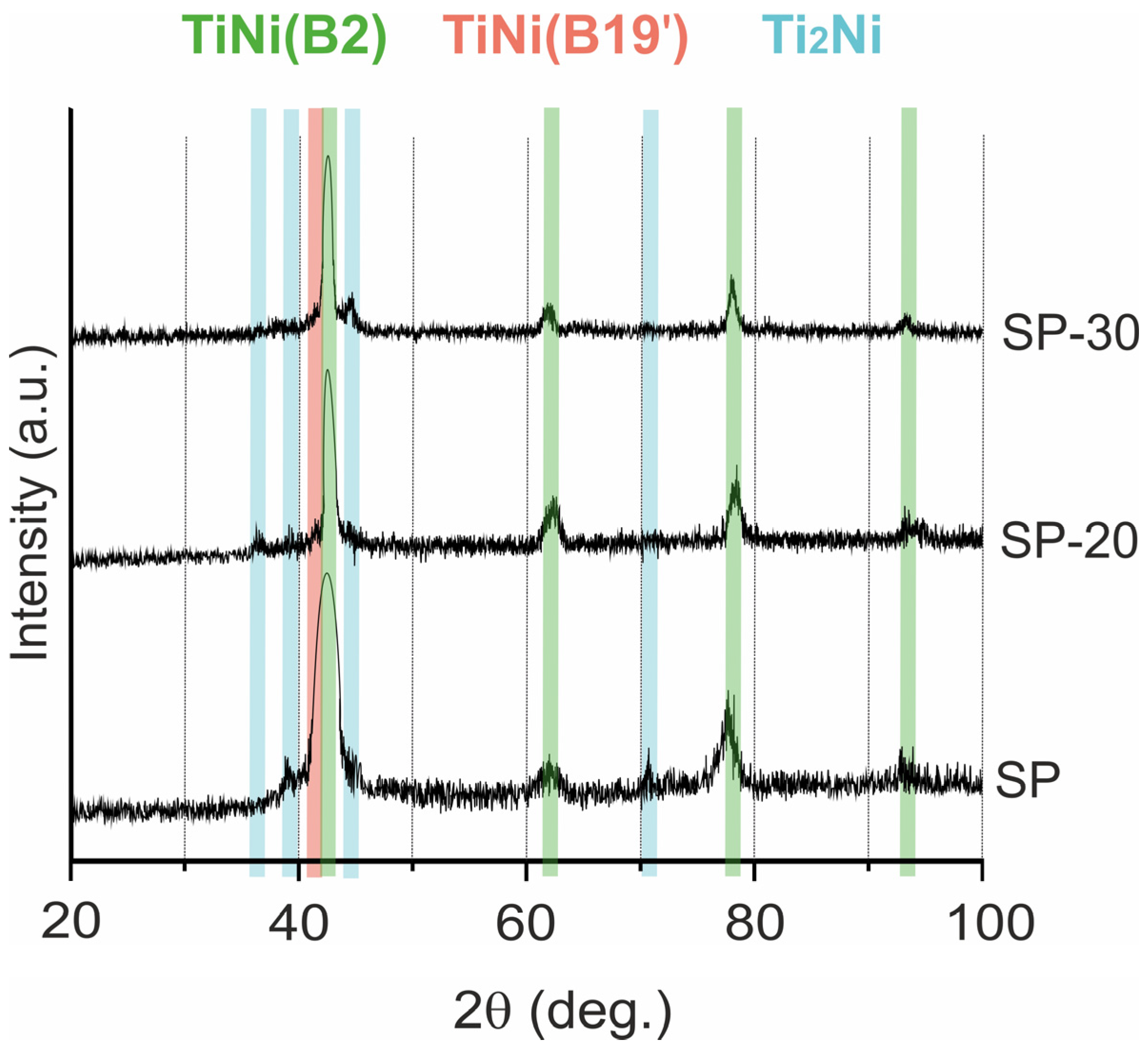
| Phase | Content in Samples (vol.%) | ||
|---|---|---|---|
| SP | SP-20 | SP-30 | |
| TiNi (B2) | 73 | 85 | 91 |
| TiNi (B19′) | 15 | 9 | 5 |
| Ti2Ni | 12 | 6 | 4 |
| Sample | Icorr, µA | Ecorr, mV | Ra, µm | , mm/year |
|---|---|---|---|---|
| LP | 0.936 | −345.6 | 80 | 7.3 × 10⁻⁵ |
| LP-20 | 0.533 | −391.4 | 70 | 4.8 × 10⁻⁵ |
| LP-30 | 1.44 | −350.2 | 60 | 1.5 × 10⁻⁴ |
| SP | 0.452 | −278.7 | 22 | 1.3 × 10⁻⁴ |
| SP-20 | 1.86 | −332.9 | 18 | 6.5 × 10⁻⁴ |
| SP-30 | 0.014 | −343.2 | 3 | 2.9 × 10⁻⁵ |
| Ti plate | 0.058 | −194.9 | 0.48 | 7.6 × 10⁻⁴ |
| TiNi-Pl. | 0.742 | −358.5 | 1.41 | 3.3 × 10⁻³ |
| TiNi-Pl./t | 0.036 | −313.6 | 0.55 | 4.3 × 10⁻⁴ |
Disclaimer/Publisher’s Note: The statements, opinions and data contained in all publications are solely those of the individual author(s) and contributor(s) and not of MDPI and/or the editor(s). MDPI and/or the editor(s) disclaim responsibility for any injury to people or property resulting from any ideas, methods, instructions or products referred to in the content. |
© 2023 by the authors. Licensee MDPI, Basel, Switzerland. This article is an open access article distributed under the terms and conditions of the Creative Commons Attribution (CC BY) license (https://creativecommons.org/licenses/by/4.0/).
Share and Cite
Shabalina, A.V.; Anikeev, S.G.; Kulinich, S.A.; Artyukhova, N.V.; Vlasov, V.A.; Kaftaranova, M.I.; Hodorenko, V.N.; Yakovlev, E.V.; Pesterev, E.A.; Lukyanenko, A.V.; et al. Combined Porous-Monolithic TiNi Materials Surface-Modified with Electron Beam for New-Generation Rib Endoprostheses. J. Funct. Biomater. 2023, 14, 277. https://doi.org/10.3390/jfb14050277
Shabalina AV, Anikeev SG, Kulinich SA, Artyukhova NV, Vlasov VA, Kaftaranova MI, Hodorenko VN, Yakovlev EV, Pesterev EA, Lukyanenko AV, et al. Combined Porous-Monolithic TiNi Materials Surface-Modified with Electron Beam for New-Generation Rib Endoprostheses. Journal of Functional Biomaterials. 2023; 14(5):277. https://doi.org/10.3390/jfb14050277
Chicago/Turabian StyleShabalina, Anastasiia V., Sergey G. Anikeev, Sergei A. Kulinich, Nadezhda V. Artyukhova, Vitaly A. Vlasov, Maria I. Kaftaranova, Valentina N. Hodorenko, Evgeny V. Yakovlev, Evgeny A. Pesterev, Anna V. Lukyanenko, and et al. 2023. "Combined Porous-Monolithic TiNi Materials Surface-Modified with Electron Beam for New-Generation Rib Endoprostheses" Journal of Functional Biomaterials 14, no. 5: 277. https://doi.org/10.3390/jfb14050277