

Accuracy and Technical Predictability of Computer Guided Bone Harvesting from the Mandible: A Cone-Beam CT Analysis in 22 Consecutive Patients
 , ,
, ,  and
and
Abstract
:1. Introduction
2. Materials and Methods
2.1. Study Population and Patients’ Groups
2.2. Computer-Aided Surgical Planning
2.3. Surgical Procedure
2.4. Accuracy Assessment
2.5. Statistical Analysis
3. Results
3.1. Overall Accuracy and Cutting Planes Features
3.2. Groups Analysis
4. Discussion
5. Conclusions
Author Contributions
Funding
Institutional Review Board Statement
Informed Consent Statement
Data Availability Statement
Conflicts of Interest
References
- Tonetti, M.S.; Hämmerle, C.H.F.; on behalf of the European Workshop on Periodontology Group C. Advances in bone augmentation to enable dental implant placement: Consensus Report of the Sixth European Workshop on Periodontology. J. Clin. Periodontol. 2008, 35, 168–172. [Google Scholar] [CrossRef] [PubMed] [Green Version]
- Jensen, A.T.; Jensen, S.S.; Worsaae, N. Complications related to bone augmentation procedures of localized defects in the alveolar ridge. A retrospective clinical study. Oral Maxillofac. Surg. 2016, 20, 115–122. [Google Scholar] [CrossRef] [PubMed]
- Schmitt, C.M.; Doering, H.; Schmidt, T.; Lutz, R.; Neukam, F.W.; Schlegel, K.A. Histological results after maxillary sinus augmentation with Straumann® BoneCeramic, Bio-Oss®, Puros®, and autologous bone. A randomized controlled clinical trial. Clin. Oral Implant. Res. 2012, 24, 576–585. [Google Scholar] [CrossRef] [PubMed]
- Chiapasco, M.; Zaniboni, M.; Rimondini, L. Autogenous onlay bone grafts vs. alveolar distraction osteogenesis for the correction of vertically deficient edentulous ridges: A 2–4 year prospective study on humans. Clin. Oral Implant. Res. 2007, 18, 432–440. [Google Scholar] [CrossRef] [PubMed]
- Jensen, S.S.; Terheyden, H. Bone augmentation procedures in localized defects in the alveolar ridge: Clinical results with different bone grafts and bone-substitute materials. Int. J. Oral Maxillofac. Implant. 2009, 24, 218–236. [Google Scholar]
- Pistilli, R.; Felice, P.; Piatelli, M.; Nisii, A.; Barausse, C.; Esposito, M. Blocks of autogenous bone versus xenografts for the rehabilitation of atrophic jaws with dental implants: Preliminary data from a pilot randomised controlled trial. Eur. J. Oral Implant. 2014, 7, 153–171. [Google Scholar]
- Sakkas, A.; Wilde, F.; Heufelder, M.; Winter, K.; Schramm, A. Autogenous bone grafts in oral implantology—Is it still a “gold standard”? A consecutive review of 279 patients with 456 clinical procedures. Int. J. Implant. Dent. 2017, 3, 23. [Google Scholar] [CrossRef]
- Sakkas, A.; Ioannis, K.; Winter, K.; Schramm, A.; Wilde, F. Clinical results of autologous bone augmentation harvested from the mandibular ramus prior to implant placement. An analysis of 104 cases. GMS Interdiscip. Plast. Reconstr. Surg. DGPW 2016, 5, Doc21. [Google Scholar] [CrossRef]
- Misch, C.M. Ridge augmentation using mandibular ramus bone grafts for the placement of dental implants: Presentation of a technique. Pr. Periodontics Aesthet. Dent. PPAD 1996, 8, 127–135. [Google Scholar]
- Happe, A. Use of a piezoelectric surgical device to harvest bone grafts from the mandibular ramus: Report of 40 cases. Int. J. Periodontics Restor. Dent. 2007, 27, 241–249. [Google Scholar]
- Khoury, F.; Khoury, C. Mandibular bone block grafts: Diagnosis, instrumentation, harvesting techniques and surgical pro-cedures. In Bone Augmentation in Oral Implantology; Quintessence: London, UK, 2007; pp. 115–212. [Google Scholar]
- Clavero, J.; Lundgren, S. Ramus or Chin Grafts for Maxillary Sinus Inlay and Local Onlay Augmentation: Comparison of Donor Site Morbidity and Complications. Clin. Implant. Dent. Relat. Res. 2003, 5, 154–160. [Google Scholar] [CrossRef] [PubMed]
- Nkenke, E.; Neukam, F.W. Autogenous bone harvesting and grafting in advanced jaw resorption: Morbidity, resorption and implant survival. Eur. J. Oral Implant. 2014, 7 (Suppl. S2), S203–S217. [Google Scholar]
- Reininger, D.; Cobo-Vazquez, C.; Monteserin-Matesanz, M.; Lopez-Quiles, J. Complications in the use of the mandibular body, ramus and symphysis as donor sites in bone graft surgery. A systematic review. Med. Oeal Patol. Oral Cir. Bucal. 2016, 21, e241–e249. [Google Scholar] [CrossRef] [PubMed]
- Jacobs, R.; Salmon, B.; Codari, M.; Hassan, B.; Bornstein, M.M. Cone beam computed tomography in implant dentistry: Recommendations for clinical use. BMC Oral Health 2018, 18, 88. [Google Scholar] [CrossRef] [Green Version]
- Cordaro, L.; Torsello, F.; Morcavallo, S.; Di Torresanto, V.M. Effect of bovine bone and collagen membranes on healing of mandibular bone blocks: A prospective randomized controlled study. Clin. Oral Implant. Res. 2011, 22, 1145–1150. [Google Scholar] [CrossRef]
- Schneider, D.; Marquardt, P.; Zwahlen, M.; Jung, R.E. A systematic review on the accuracy and the clinical outcome of computer-guided template-based implant dentistry. Clin. Oral Implant. Res. 2009, 20 (Suppl. 4), 73–86. [Google Scholar] [CrossRef] [Green Version]
- D’Haese, J.; Van De Velde, T.; Komiyama, A.; Hultin, M.; De Bruyn, H. Accuracy and Complications Using Computer-Designed Stereolithographic Surgical Guides for Oral Rehabilitation by Means of Dental Implants: A Review of the Literature. Clin. Implant. Dent. Relat. Res. 2010, 14, 321–335. [Google Scholar] [CrossRef]
- Van Assche, N.; Vercruyssen, M.; Coucke, W.; Teughels, W.; Jacobs, R.; Quirynen, M. Accuracy of computer-aided implant placement. Clin. Oral Implant. Res. 2012, 23, 112–123. [Google Scholar] [CrossRef]
- Bover-Ramos, F.; Viña-Almunia, J.; Cervera-Ballester, J.; Peñarrocha-Diago, M.; García-Mira, B. Accuracy of Implant Placement with Computer-Guided Surgery: A Systematic Review and Meta-Analysis Comparing Cadaver, Clinical, and In Vitro Studies. Int. J. Oral Maxillofac. Implant. 2018, 33, 101–115. [Google Scholar] [CrossRef]
- Marlière, D.A.A.; Demètrio, M.S.; Picinini, L.S.; De Oliveira, R.G.; Netto, H.D.D.M.C. Accuracy of computer-guided surgery for dental implant placement in fully edentulous patients: A systematic review. Eur. J. Dent. 2018, 12, 153–160. [Google Scholar] [CrossRef]
- Seo, C.; Juodzbalys, G. Accuracy of Guided Surgery via Stereolithographic Mucosa-Supported Surgical Guide in Implant Surgery for Edentulous Patient: A Systematic Review. J. Oral Maxillofac. Res. 2018, 9, e1. [Google Scholar] [CrossRef] [PubMed]
- Zhu, N.; Liu, J.; Ma, T.; Zhang, Y.; Lin, Y. Fully digital versus conventional workflow for horizontal ridge augmentation with intraoral block bone: A randomized controlled clinical trial. Clin. Implant Dent. Relat. Res. 2022. [Google Scholar] [CrossRef] [PubMed]
- Wang, J.; Luo, Y.; Qu, Y.; Man, Y. Horizontal ridge augmentation in the anterior maxilla with in situ onlay bone grafting: A retrospective cohort study. Clin. Oral Investig. 2022, 26, 5893–5908. [Google Scholar] [CrossRef] [PubMed]
- De Stavola, L.; Fincato, A.; Albiero, A.M. A computer-guided bone block harvesting procedure: A proof-of-principle case report and technical notes. Int. J. Oral Maxillofac. Implant. 2015, 30, 1409–1413. [Google Scholar] [CrossRef] [Green Version]
- De Stavola, L.; Fincato, A.; Bressan, E.; Gobbato, L. Results of Computer-Guided Bone Block Harvesting from the Mandible: A Case Series. Int. J. Periodontics Restor. Dent. 2017, 37, e111–e119. [Google Scholar] [CrossRef]
- De Stavola, L.; Fincato, A. Method for Making a Surgical Guide for Bone Harvesting. U.S. Patent 10,242,127, 3 March 2014. [Google Scholar]
- Cristoforetti, A.; De Stavola, L.; Fincato, A.; Masè, M.; Ravelli, F.; Nollo, G.; Tessarolo, F. Assessing the accuracy of computer-planned osteotomy guided by stereolithographic template: A methodological framework applied to the mandibular bone harvesting. Comput. Biol. Med. 2019, 114, 103435. [Google Scholar] [CrossRef]
- Khoury, F.; Hanser, T. Mandibular Bone Block Harvesting from the Retromolar Region: A 10-Year Prospective Clinical Study. Int. J. Oral Maxillofac. Implant. 2015, 30, 688–697. [Google Scholar] [CrossRef] [Green Version]
- van Baar, G.J.; Forouzanfar, T.; Liberton, N.P.; Winters, H.A.; Leusink, F.K. Accuracy of computer-assisted surgery in mandibular reconstruction: A systematic review. Oral Oncol. 2018, 84, 52–60. [Google Scholar] [CrossRef]
- Annino, D.J.; Sethi, R.K.; Hansen, E.E.; Horne, S.; Dey, T.; Rettig, E.M.; Uppaluri, R.; Kass, J.I.; Goguen, L.A. Virtual planning and 3D-printed guides for mandibular reconstruction: Factors impacting accuracy. Laryngoscope Investig. Otolaryngol. 2022, 1–10. [Google Scholar] [CrossRef]
- Roser, S.M.; Ramachandra, S.; Blair, H.; Grist, W.; Carlson, G.W.; Christensen, A.M.; Weimer, K.A.; Steed, M.B. The Accuracy of Virtual Surgical Planning in Free Fibula Mandibular Reconstruction: Comparison of Planned and Final Results. J. Oral Maxillofac. Surg. 2010, 68, 2824–2832. [Google Scholar] [CrossRef]
- Foley, B.D.; Thayer, W.P.; Honeybrook, A.; McKenna, S.; Press, S. Mandibular Reconstruction Using Computer-Aided Design and Computer-Aided Manufacturing: An Analysis of Surgical Results. J. Oral Maxillofac. Surg. 2013, 71, e111–e119. [Google Scholar] [CrossRef] [PubMed]
- Shu, D.-L.; Liu, X.-Z.; Guo, B.; Ran, W.; Liao, X.; Zhang, Y.-Y. Accuracy of using computer-aided rapid prototyping templates for mandible reconstruction with an iliac crest graft. World J. Surg. Oncol. 2014, 12, 190. [Google Scholar] [CrossRef] [PubMed] [Green Version]
- Metzler, P.; Geiger, E.J.; Alcon, A.; Ma, X.; Steinbacher, D.M. Three-Dimensional Virtual Surgery Accuracy for Free Fibula Mandibular Reconstruction: Planned Versus Actual Results. J. Oral Maxillofac. Surg. 2014, 72, 2601–2612. [Google Scholar] [CrossRef]
- Schepers, R.H.; Raghoebar, G.M.; Vissink, A.; Stenekes, M.W.; Kraeima, J.; Roodenburg, J.L.; Reintsema, H.; Witjes, M.J. Accuracy of fibula reconstruction using patient-specific CAD/CAM reconstruction plates and dental implants: A new modality for functional reconstruction of mandibular defects. J. Craniomaxillofac. Surg. 2015, 43, 649–657. [Google Scholar] [CrossRef]
- Weijs, W.L.; Coppen, C.; Schreurs, R.; Vreeken, R.D.; Verhulst, A.C.; Merkx, M.A.; Bergé, S.J.; Maal, T.J. Accuracy of virtually 3D planned resection templates in mandibular reconstruction. J. Craniomaxillofac. Surg. 2016, 44, 1828–1832. [Google Scholar] [CrossRef]
- Ren, W.; Gao, L.; Li, S.; Chen, C.; Li, F.; Wang, Q.; Zhi, Y.; Song, J.; Dou, Z.; Xue, L.; et al. Virtual Planning and 3D printing modeling for mandibular reconstruction with fibula free flap. Med. Oral. Patol. Oral. Cir. Bucal. 2018, 98, e359–e366. [Google Scholar] [CrossRef] [PubMed]
- Pietruski, P.; Majak, M.; Swiatek-Najwer, E.; Popek, M.; Szram, D.; Zuk, M.; Jaworowski, J. Accuracy of experimental mandibular osteotomy using the image-guided sagittal saw. Int. J. Oral Maxillofac. Surg. 2016, 45, 793–800. [Google Scholar] [CrossRef]
- Bernstein, J.M.; Daly, M.; Chan, H.; Qiu, J.; Goldstein, D.; Muhanna, N.; De Almeida, J.R.; Irish, J.C. Accuracy and reproducibility of virtual cutting guides and 3D-navigation for osteotomies of the mandible and maxilla. PLoS ONE 2017, 12, e0173111. [Google Scholar] [CrossRef] [PubMed]
- ter Braak, T.P.; de Koning, S.G.B.; van Alphen, M.J.A.; van der Heijden, F.; Schreuder, W.H.; van Veen, R.L.P.; Karakullukcu, M.B. A surgical navigated cutting guide for mandibular osteotomies: Accuracy and reproducibility of an image-guided mandibular osteotomy. Int. J. Comput. Assist. Radiol. Surg. 2020, 15, 1719–1725. [Google Scholar] [CrossRef]
- Tarce, M.; Merheb, J.; Meeus, M.; Vasconcelos, K.D.F.; Quirynen, M. Surgical guides for guided bone augmentation: An in vitro study. Clin. Oral Implant. Res. 2022, 33, 558–567. [Google Scholar] [CrossRef]
- Battles, J.B. Improving patient safety by instructional systems design. Qual. Saf. Health Care 2006, 15, i25–i29. [Google Scholar] [CrossRef] [PubMed]


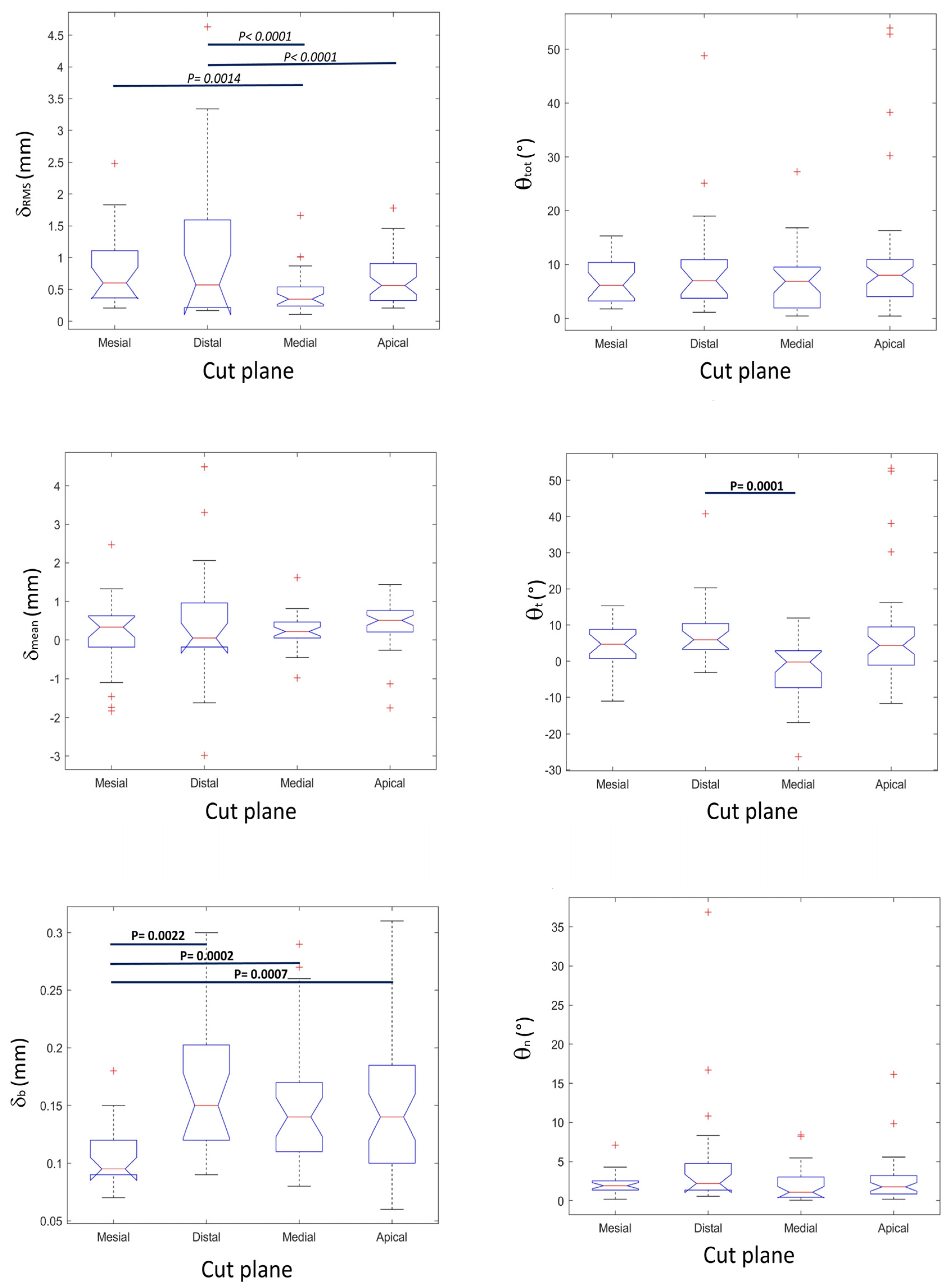
| Displacement Indexes (mm) Median (First Quartile–Third Quartile) | Angular Discrepancy Indexes (°) Median (First Quartile–Third Quartile) | |||||
|---|---|---|---|---|---|---|
| δRMS | δmean | δb | θtot | θt | θn | |
| Mesial osteotomy | 0.60 (0.37–1.11) | 0.33 (−0.18–0.63) | 0.095 (0.09–0.12) | 6.12 (3.23–10.37) | 4.73 (0.74–8.73) | 1.91 (1.35–2.54) |
| Distal osteotomy | 0.57 (0.22–1.59) | 0.05 (−0.18–0.96) | 0.15 (0.12–0.20) | 6.98 (3.75–10.91) | 5.89 (3.26–10.38) | 2.20 (1.35–4.76) |
| Medial osteotomy | 0.35 (0.24–0.54) | 0.22 (0.05–0.46) | 0.14 (0.11–0.17) | 6.88 (1.95–9.53) | −0.20 (−7.31–2.91) | 1.08 (0.43–3.03) |
| Apical osteotomy | 0.56 (0.33–0.91) | 0.51 (0.21–0.77) | 0.14 (0.10–0.18) | 7.98 (4.06–10.95) | 4.39 (−1.10–9.43) | 1.76 (0.85–3.21) |
| Overall | 0.52 (0.30–0.97) | 0.28 (0.05–0.62) | 0.14 (0.10–0.17) | 6.91 (3.30–10.12) | 3.29 (−1.11–8.79) | 1.77 (0.90–3.22) |
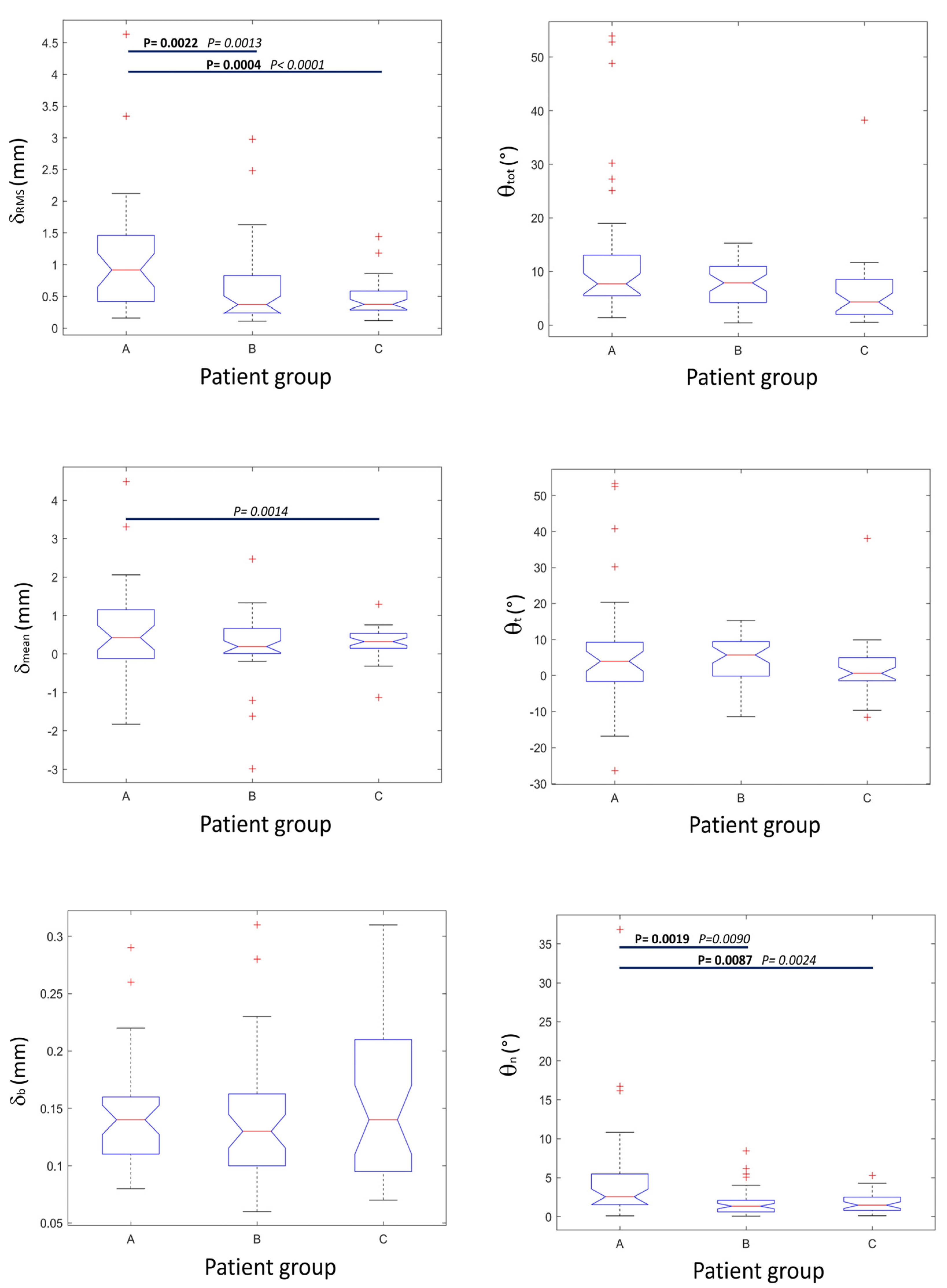
| Displacement Indexes (mm) Median (First Quartile–Third Quartile) | Angular Discrepancy Indexes (°) Median (First Quartile–Third Quartile) | |||||
|---|---|---|---|---|---|---|
| δRMS | δmean | δb | θtot | θt | θn | |
| Group A | 0.91 (0.42–1.46) | 0.42 (−0.12–1.15) | 0.14 (0.11–0.16) | 7.72 (5.49–13.06) | 3.97 (−1.68–9.23) | 2.54 (1.54–5.49) |
| Group B | 0.37 (0.24–0.83) | 0.19 (0.01–0.66) | 0.13 (0.10–0.16) | 7.90 (4.21–10.95) | 5.72 (−0.18–9.43) | 1.35 (0.60–2.11) |
| Group C | 0.37 (0.28–0.58) | 0.32 (0.14–0.53) | 0.14 (0.09–0.21) | 4.30 (2.00–8.55) | 0.60 (−1.50–4.96) | 1.48 (0.80–2.47) |
Publisher’s Note: MDPI stays neutral with regard to jurisdictional claims in published maps and institutional affiliations. |
© 2022 by the authors. Licensee MDPI, Basel, Switzerland. This article is an open access article distributed under the terms and conditions of the Creative Commons Attribution (CC BY) license (https://creativecommons.org/licenses/by/4.0/).
Share and Cite
De Stavola, L.; Cristoforetti, A.; Fincato, A.; Nollo, G.; Ghensi, P.; Cantarutti, A.; Tessarolo, F. Accuracy and Technical Predictability of Computer Guided Bone Harvesting from the Mandible: A Cone-Beam CT Analysis in 22 Consecutive Patients. J. Funct. Biomater. 2022, 13, 292. https://doi.org/10.3390/jfb13040292
De Stavola L, Cristoforetti A, Fincato A, Nollo G, Ghensi P, Cantarutti A, Tessarolo F. Accuracy and Technical Predictability of Computer Guided Bone Harvesting from the Mandible: A Cone-Beam CT Analysis in 22 Consecutive Patients. Journal of Functional Biomaterials. 2022; 13(4):292. https://doi.org/10.3390/jfb13040292
Chicago/Turabian StyleDe Stavola, Luca, Alessandro Cristoforetti, Andrea Fincato, Giandomenico Nollo, Paolo Ghensi, Anna Cantarutti, and Francesco Tessarolo. 2022. "Accuracy and Technical Predictability of Computer Guided Bone Harvesting from the Mandible: A Cone-Beam CT Analysis in 22 Consecutive Patients" Journal of Functional Biomaterials 13, no. 4: 292. https://doi.org/10.3390/jfb13040292