Article

Hydraulic Performance Optimization of a Submersible Drainage Pump

1
National Research Center of Pumps, Jiangsu University, Zhenjiang 212013, China
2
Department of Mechanical Engineering, International University of Business Agriculture and Technology, Dhaka 1230, Bangladesh
3
School of Mechanical Engineering, Soongsil University, Seoul 06978, Republic of Korea
4
IVAI Ltd., Gangseo-gu, Seoul 157-754, Republic of Korea
5
Daeyoung Power Pump, Hwaseong City 445-861, Republic of Korea
*
Authors to whom correspondence should be addressed.
Computation 2024, 12(1), 12; https://doi.org/10.3390/computation12010012
Submission received: 18 November 2023 / Revised: 7 December 2023 / Accepted: 8 January 2024 / Published: 10 January 2024

Abstract

:
Small submersible drainage pumps are used to discharge leaking water and rainwater in buildings. In an emergency (e.g., heavy rain or accident), advance monitoring of the flow rate is essential to enable optimal operation, considering the point where the pump operates abnormally when the water level is increased rapidly. Moreover, pump performance optimization is crucial for energy-saving policy. Therefore, it is necessary to meet the challenges of submersible pump systems, including sustainability and pump efficiency. The final goal of this study was to develop an energy-saving and highly efficient submersible drainage pump capable of performing efficiently in emergencies. In particular, this paper targeted the hydraulic performance improvement of a submersible drainage pump model. Prior to the development of driving-mode-related technology capable of emergency response, a way to improve the performance characteristics of the existing submersible drainage pump was found. Disassembling of the current pump followed by reverse engineering was performed instead of designing a new pump. Numerical simulation was performed to analyze the flow characteristics and pump efficiency. An experiment was carried out to obtain the performance, and it was validated with numerical results. The results reveal that changing the cross-sectional shape of the impeller reduced the flow separation and enhanced velocity and pressure distributions. Also, it reduced the power and increased efficiency. The results also show that the pump’s efficiency was increased to 5.56% at a discharge rate of 0.17 m3/min, and overall average efficiency was increased to 6.53%. It was concluded that the submersible pump design method is suitable for the numerical designing of an optimized pump’s impeller and casing. This paper provides insight on the design optimization of pumps.

1. Introduction

This study focused on the performance improvement of submersible drainage pumps. Submersible drainage pumps are divided into two categories. One is referred to as “large submersible pumps”, which are used for drainage (rainwater) pumping stations, and the other is known as “small submersible pumps”, which are used in buildings. Small submersible drainage pumps are used for draining from buildings when leakage and rainwater flow into the basement [1,2,3]. The TRL (Technology Readiness Level) of submersible drainage pumps is 7–9, and it is a situation from which no unique technology will arise. Existing technology patents also utilize technology used in other fields. According to patent acquisition, vibration sensors are installed on the pump shaft to solve the blocking phenomenon caused by foreign substances and vibration problems caused by, e.g., cavitation. The shape of the impeller can be changed without impacting performance to prevent the clogging of foreign substances or improve existing monitoring technologies. Pump efficiency is a significant energy-saving policy factor [4,5]. If pump efficiency increases, a significant amount of energy will be saved.
Due to the complicated, implicit relationship between hydraulic performance and the complex geometry shape of impeller passages, the study of optimization and the inverse problem of the submersible pump is moving slowly [6,7]. Shi et al. [8] started to design a new submersible pump for deep wells with the computational fluid dynamics (CFD) technique. They achieved sufficient pump efficiency compared with that of traditional pumps. Zhu et al. [9] investigated a mechanistic model for improving system performance with gas–liquid flow in a submersible pump. Manivannan [10] conducted a study on the computational fluid dynamics of a mixed-flow pump to predict the flow pattern inside the impeller. Different parameters and optimization techniques were used to obtain optimal output for the pump impeller numerically [11]. The pump impeller head was optimized using various optimization algorithms to reduce frictional loss during pump operation [12]. Using an inverse design, Zangeneth et al. [13] investigated using a mixed-flow pump for suppressing secondary flows. Afterwards, they [14] performed an experimental study to confirm the validity of the model pump. Kim et al. [15] attempted to improve suction performance and efficiency by optimizing a mixed-flow pump with the CFD technique. Another researcher [16] studied the suction performance improvement of mixed-flow pumps. The result exhibited that the specific speed and shape of the pump’s impeller greatly influence the suction performance.
Yan et al. [17] investigated a CFD-based pump redesign of a centrifugal to improve efficiency and decrease unsteady radial forces. The CFD method was applied to study the effect of the volute and the number of impeller blades and trailing-edge modification of pumps [18,19]. Qian et al. [20] adopted the Plackett–Buram test design method for the performance optimization of multistage centrifugal pumps. The results showed a significantly impacted pump axial force and hydraulic performance when considering the blade exit angle, outlet diameter, blade wrap angle, etc. Liu et al. [21] studied the RBF neural network and particle swarm optimization method to improve the performance of submersible well pumps. They found that the pressure gradient in the impeller was increased, and the pressure amplitude of the impeller was significantly reduced. Ling Bai et al. [22] highlighted the performance improvement of an EPS impeller based on the Taguchi approach and found that the front and rear shrouds of the impeller meridian significantly affect the ESP performance. Chen et al. [23] studied performance improvement of a mixed-flow pump based on the entropy production method. They found that the geometric and hydrodynamic parameters greatly influenced the pump’s energy characteristics. Suh et al. [24] optimized impeller and suction performance to increase the hydraulic efficiency of a mixed-flow pump. Jeon et al. [25] conducted a study on a regenerative pump impeller and enhanced the model’s efficiency by numerical simulation and design of experiments (DoE). Siddique et al. [26] investigated the impeller design optimization of a centrifugal pump by numerically enhancing the pump head and significantly reducing the input power. Shim et al. [27] presented a study on enhancement flow recirculation and cavitation of a centrifugal pump by controlling the meridional profile of the blade. Yang et al. [28] investigated multistage ESP to improve hydraulic performance using the Taguchi optimization method. The Taguchi method was a remarkably handy tool for optimizing the ESP. Arocena et al. [29] designed and analyzed the intake structure of a submersible pump numerically. Wei et al. [30] investigated the influence of impeller gap drainage width on the performance of a low-specific-speed centrifugal pump, and the results revealed that using a smaller gap width could significantly improve the performance. Han et al. [31] presented the influence of various impeller blade outlet angles on the performance of a high-speed ESP using experimental and computational methods. It was found that the impeller vane exit angle had a significant effect on the pump performance curve. Tong et al. [32] conducted axial flow pump performance analysis experimentally and numerically. The results showed that a higher head led to increased pump rotation speed. Fakher et al. [33] studied the efficiency improvement of an electric submersible pump. They replaced the conventional motor with a permanent magnetic one to achieve prolonged ESP mean failure. The flow patterns inside an electrical submersible pump are presented using CFD and compared with visualization experiments [34]. However, the study did not show whether optimizing the shape of the pump casing and impeller can improve the hydraulic performance in a single-stage submersible drainage pump.
Therefore, this study focused especially on the hydraulic performance optimization of a centrifugal-type submersible drainage pump as a development target. To improve our understanding of the flow characteristics inside pumps, existing and developed pumps’ performances were analyzed through simulations and experiments. Moreover, this study was intended to provide a basic design of the pump shape to enhance the performance of significant parts, manufacture parts and conduct pump tests using 3D printing technology. In addition, primary research findings were patented based on the developed technology.

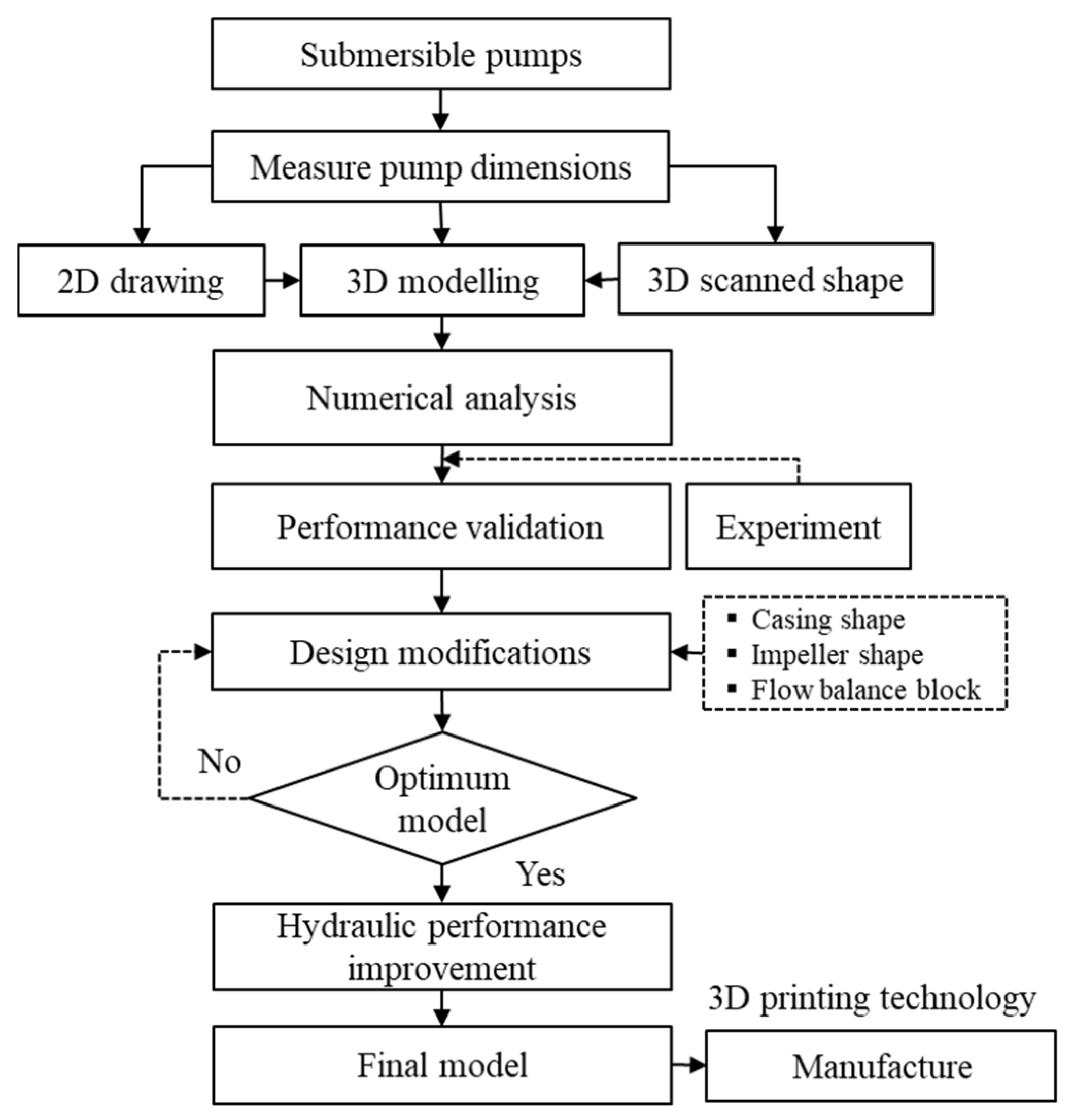
2. Materials and Methods

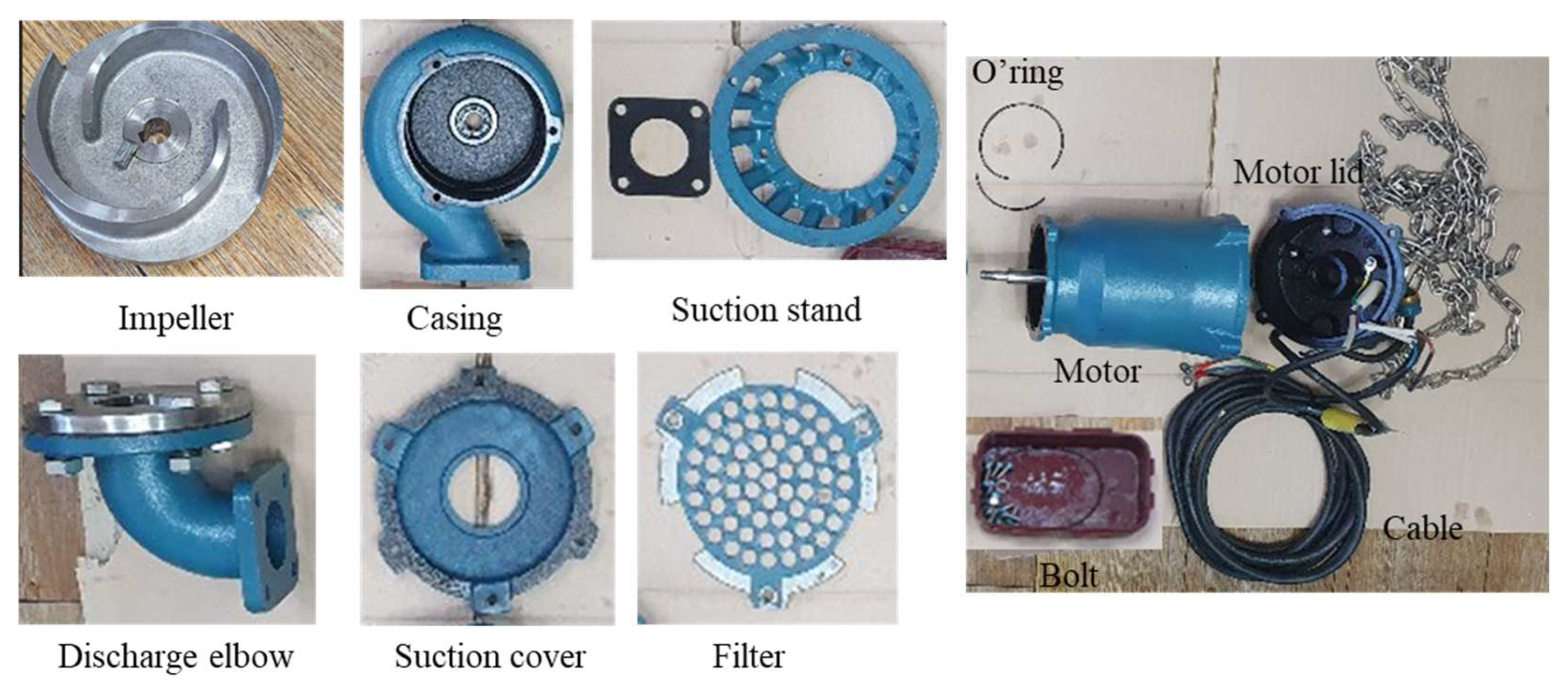
2.1. Pump Dimensions and 3D Model

Three-dimensional scanning was performed to accurately obtain the dimensions of the pump casing and impeller to be analyzed. For this purpose, a DWE-08B submersible drainage pump was disassembled, as shown in Figure 1. The exact dimensions of the pump were required for analysis through computational methods. Of the pump components, only the significant parts of the pump impeller and casing were scanned using a noncontact portable 3D scanner (Creaform 50, with a tolerance of 1/100, Creaform, Lévis, QC, Canada). The software generated the three-dimensional geometrical shape and imported it to CAD software (ANSYS-ICEM (21R2)) for cleaning.
This study used ANSYS-ICEM commercial software to clean-scan 3D geometry and create an .STP file. Figure 2 shows an assembly and disassembly drawing of the vertical semi-open-type submersible pump (model—DWE-08B). Figure 3 illustrates the cross-sectional view of the main components of the pump. Table 1 presents the major design dimensions of the pump impeller and the casing obtained from the pump company’s catalog.

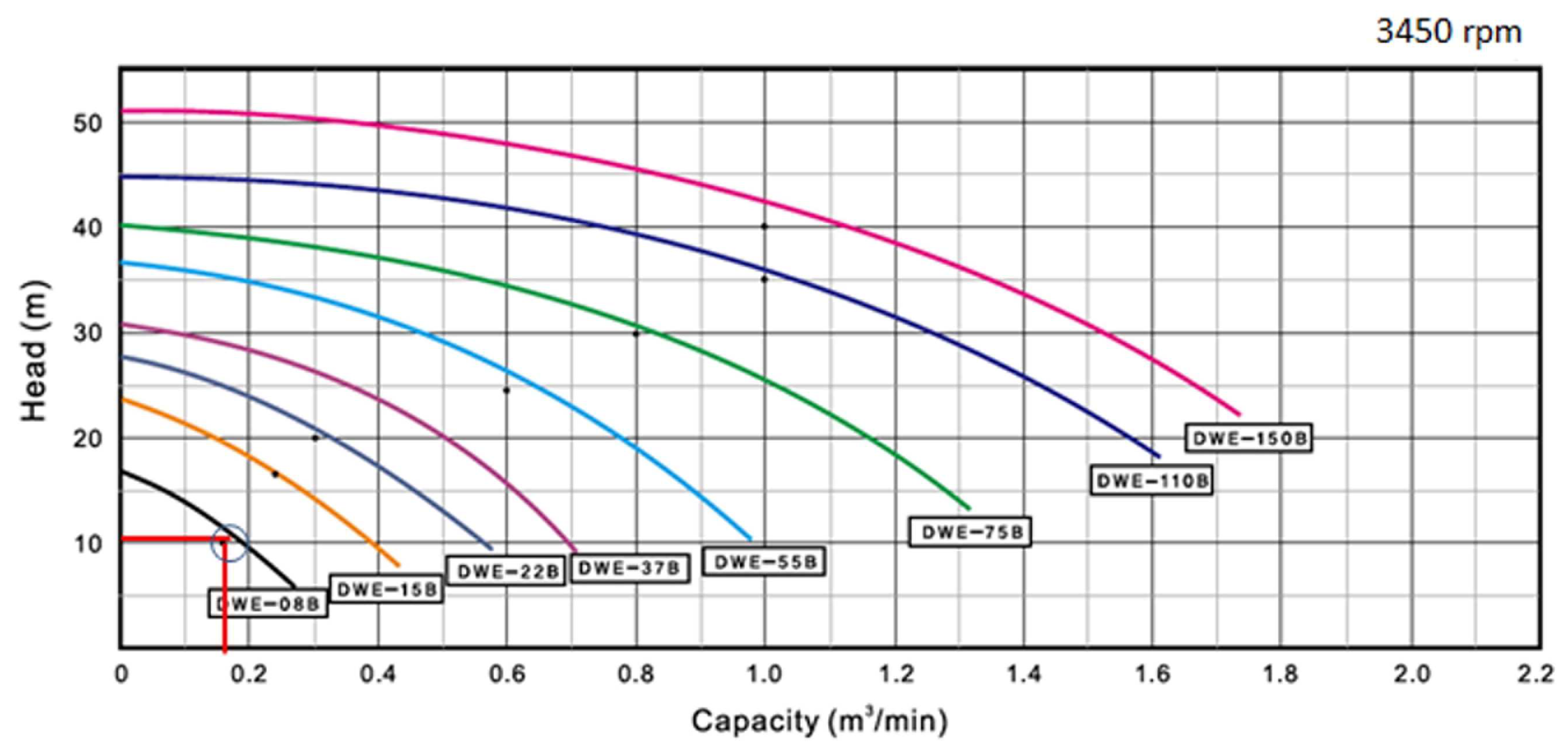
2.2. Specifications of the Submersible Pump

The pump company only provided the major pump specifications. Figure 4 illustrates the various pump models’ performance curves. The DWE-08B model performance data are represented in the black curve with a circle and red line. Table 2 shows the submersible pump’s data, as presented in the pump company’s catalog [2]. Specific points of the subject pump were determined from the record. Figure 5 illustrates the hydraulic performance optimization procedure.

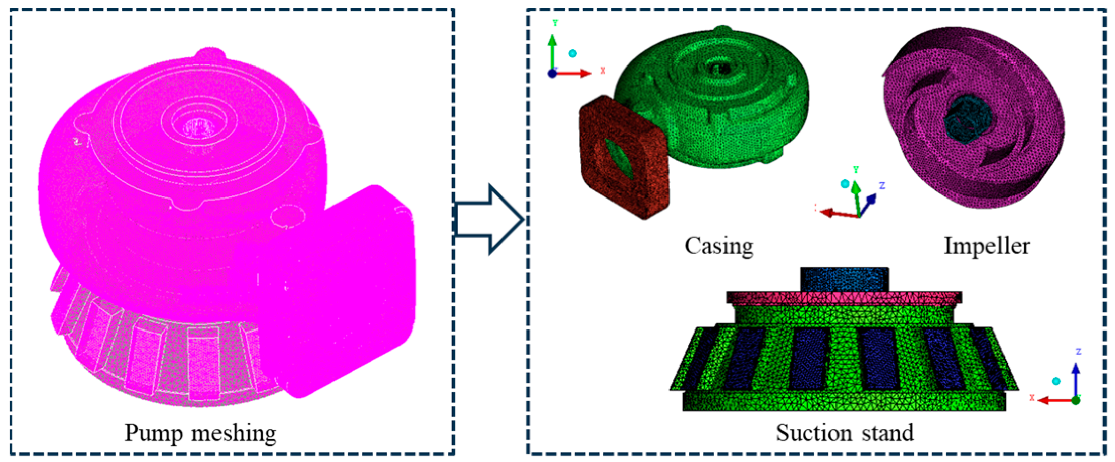
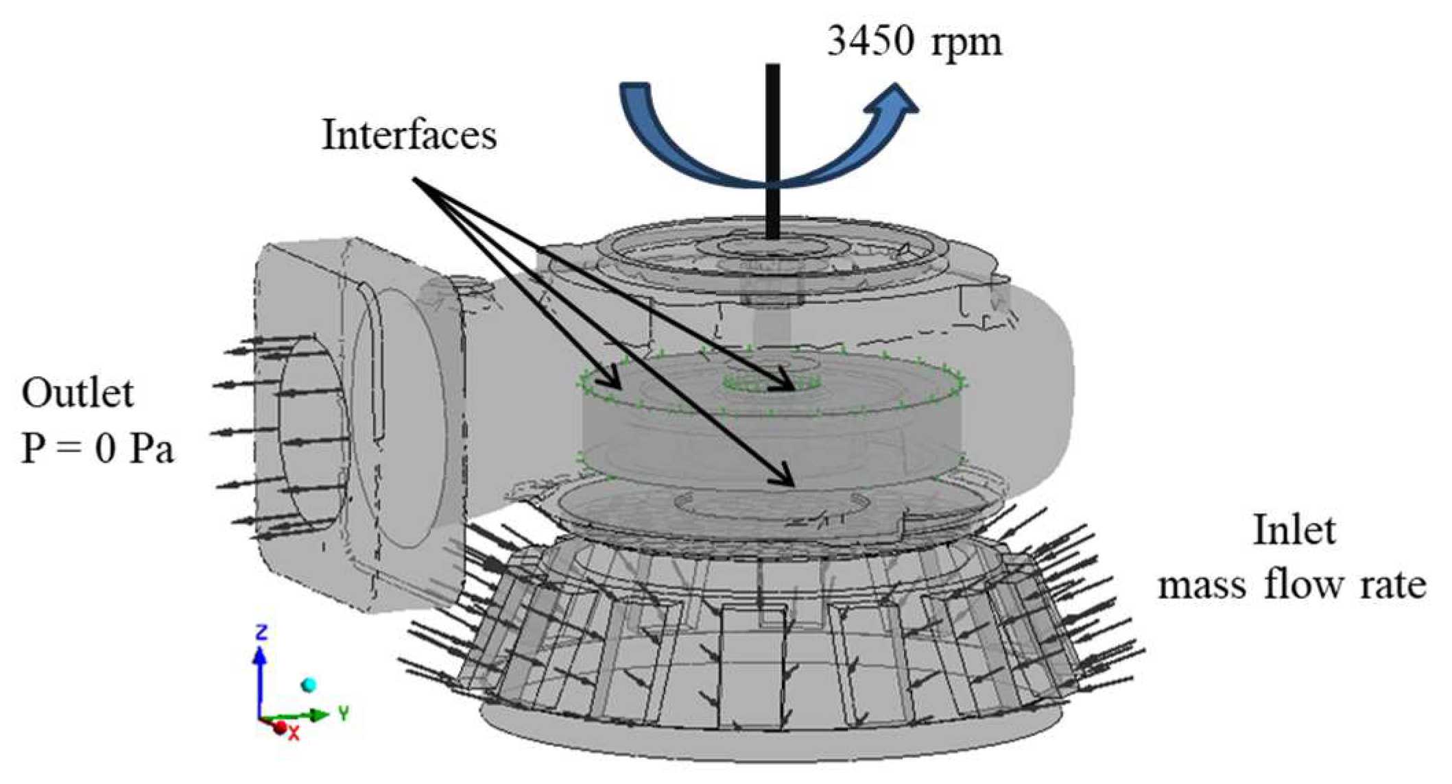
2.3. Computational Domain and Boundary Conditions

The ANSYS ICEM-CFX commercial software (21R2, ANSYS Inc., Canonsburg, PA, USA, 2021) based on the finite volume method was utilized for grid generation and analysis of the pump. Then, unconstructed tetrahedral meshing grids were created, as shown in Figure 6. Changing the number of meshing grids confirms the grid dependency [35]. Table 3 shows the various pump meshing grids performance and relative errors. The proposed total meshed grids had 272,563 nodes and 1,374,829 elements.
To run the computer simulation, this study accounted for the Reynolds Average Navier–Stokes (RANS) equations for calculating the flow analysis of the pump [36]. The following assumptions were considered: (i) incompressible, (ii) steady-state flow and (iii) turbulence model. The fluid was assumed to be Newtonian fluid, and the thermophysical properties were constant with temperature. Under the assumptions of incompressible and steady state, the governing equations of the continuity and momentum equations (known as Navier–Stokes) are expressed as [36,37]
u i x i = 0
ρ u i t + u j u i x j = p x i + τ i j x j + S
In the above equations,  u i  represents the velocity vector, x is the component of the position vector, p is the scalar pressure,  ρ  is the density of the fluid,  τ i j  designates the stress tensor, S is the source term, and i and j represent tensor notations.
To calculate the turbulent flow, eddy viscosity was added. The SST (shear stress transport turbulence) model was considered to calculate the fluid’s turbulent shear stress [38,39]. The standard k-ω model was originally developed by Wilcox [38]. The k-ω-based SST model was developed by Menter [39] and can be used to effectively blend the robust and accurate formulation of the model in the near-wall region. This model is widely applicable in turbomachinery and pumps and can also predict the onset of flow separation under an adverse pressure gradient. Therefore, the SST model was chosen for the current application. Turbulent viscosity  μ t  was determined by solving two-transport equations: turbulent energy k and the turbulence frequency ω. The two k-ω-based equations can be expressed as
k-equation:
ρ k t + ρ u j k x j = x j μ + μ t σ k k x j + P k ρ β * k ω + P k b
ω-equation:
ρ ω t + ρ u j ω x j = x j μ + μ t σ ω ω x j + α ω k P k ρ β ω 2 + P ω b
The turbulent eddy viscosity  μ t  was calculated from
μ t = ρ k m a x ω , S · F 2
where  P k b  and  P ω b  are the shear production of turbulence, S is the invariant measure of the strain rate, and  F 2  is a blending function that restricts the limiter to the wall boundary layer defined by
F 2 = t a n h m a x 2 k β * ω y ;   500 μ ρ y 2 ω 2
The first SST blending function is formulated as
F 1 = t a n h m i n m a x k β * ω y ;   500 μ ρ y 2 ω ; 4 ρ k C D k ω σ ω 2 y 2 4
where y is the distance to the nearest wall, and  C D k ω  is the positive part of the cross-diffusion term, i.e.,
C D k ω = m a x 2 ρ 1 σ ω 2 ω k x j ω x j ,   10 10
The turbulence model coefficients are given as
α = 0.55 ,   β = 0.075 ,   β * = 0.09 ,   σ k = 2.0 ,   σ ω = 2.0
In this work, the boundary conditions used for the simulation were mass flow rate as the inlet and 0 Pa as the pressure outlet. All boundary walls were assumed to be smooth walls with no-slip conditions. A frozen rotor operating at a specific rotational speed of 3450 rpm was selected for steady-state, incompressible flow analysis. Figure 7 represents the boundary conditions for numerical analysis of the DWE-08 pump domain. The velocity and pressure residual value was 1 × 10⁻⁵, controlled by convergence criteria.

3. Results and Discussion

Section 3.1 provides the pump performance validation of the computed data. Section 3.2 describes the performance analysis of the submersible pump under different operating conditions. Additionally, design modifications of the casing and impeller are illustrated in Section 3.3. Moreover, Section 3.4 presents the pump’s hydraulic performance improvement and optimum model.

3.1. Verification of the Numerical Results

An experimental setup was constructed for comparison with the computed data to verify the reliability of the test pump that the test facility employed to meet the KSB 6321 and ISO 5198 standards [40,41]. The measurement sensors used in the test pump to obtain the test data allowed a standard deviation of ±2%. The test environmental working fluid temperature and relative humidity were 13 ± 1 °C and 32 ± 5%, respectively.
The hydraulic performance parameters such as head, volume flow rate, power and efficiency are sufficient for comparing the measured with the calculated data. The equations for pump head, energy and efficiency are expressed as
H = p 2 p 1 ρ g + V 2 2 V 1 2 2 g + z 2 z 1
P = ω T
η = ρ g Q H ω T
where H represents the pump head in m, p is the static pressure of the pump in N/m2, V is the velocity of the pump in m/s, z is the elevation of the pump in m, P is the shaft power in kW,  Q  is the volumetric flow rate in m3/min, ω is the rotational speed in rad/s, T is the toque in N·m, ρ is the working fluid density in kg/m3, and  g  is the gravitational acceleration in m/s2, respectively. Subscripts 1 and 2 denote the inlet and outlet sections of the pump.
Figure 8 presents the experimental measurement data tested by the KTC (Korea Testing Certification Institute) at the pump test facility center. By examining the results in Figure 8, it can be seen that when the flow-specific point (volumetric flow rate) was 0.165 m3/min, the total head was 10 m, and the overall efficiency was only 32.14%, which was not the same as the pump efficiency. Because the test pump was in the water and could not measure the torque, the motor’s power factor (0.78) must be considered in comparing it with the experimental results. In addition, the catalog’s performance data, test data and analysis data were all presented for each outcome. When comparing all data, the average head error value was only 0.0456%, the power average error was only 0.0808%, and the efficiency average error was only 0.0617%. The head and efficiency differences were only 0.07% and 10.18% at the design flow rate. The lower difference was observed at the higher flow rate of the pump. The standard deviation of the pump head was 0.046%, the power was 0.0047%, and the rotational speed was 1.54%. At the 95% confidence limit, the normal distribution of the test pump was measured, revealing that the uncertainty of the pump head was H ± 0.00989 m, the discharge rate was Q ± 0.00178 m3/min, the power was P ± 0.0102 kW, and the rotational speed was N ± 3.298 rpm.
First, looking at Figure 8a, there is a clear difference between the test and catalog results. As observed from the H-Q curve, the analysis results agree relatively well with the experimental data, except for the low flow rate. The two results do not match well in the low-flow region due to the influence of the grid and y+. Therefore, we decided it would be best to exclude or modify the catalog data. In comparing this with the test value, it was found that the test results are well matched when considering the motor power factor of 0.78, as mentioned in the shaft power report. The values of Samples 1 and 2 in Figure 8b are the efficiencies mentioned in the high-efficiency energy equipment report. Moreover, in this study, the mechanical losses of the submersible pump were not taken into consideration in the numerical analysis.

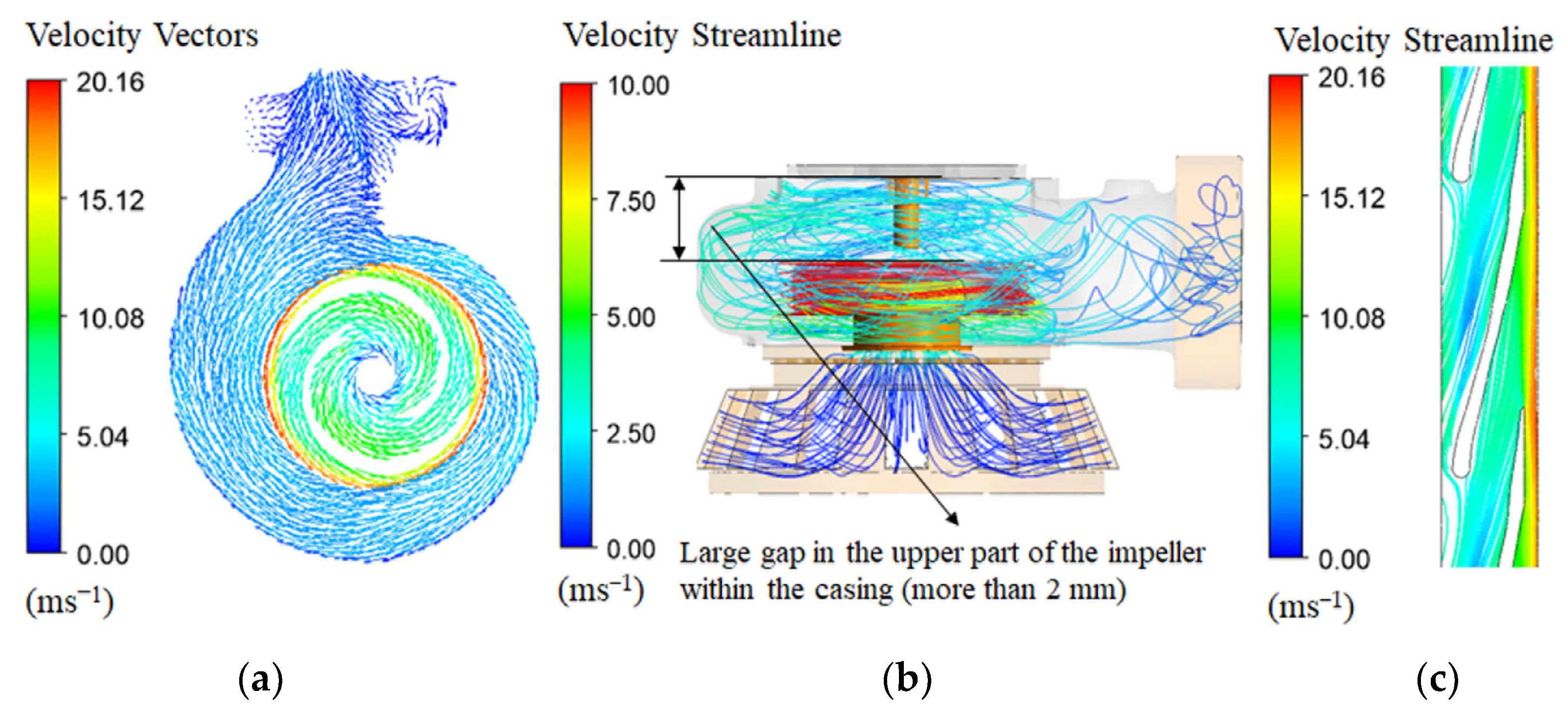
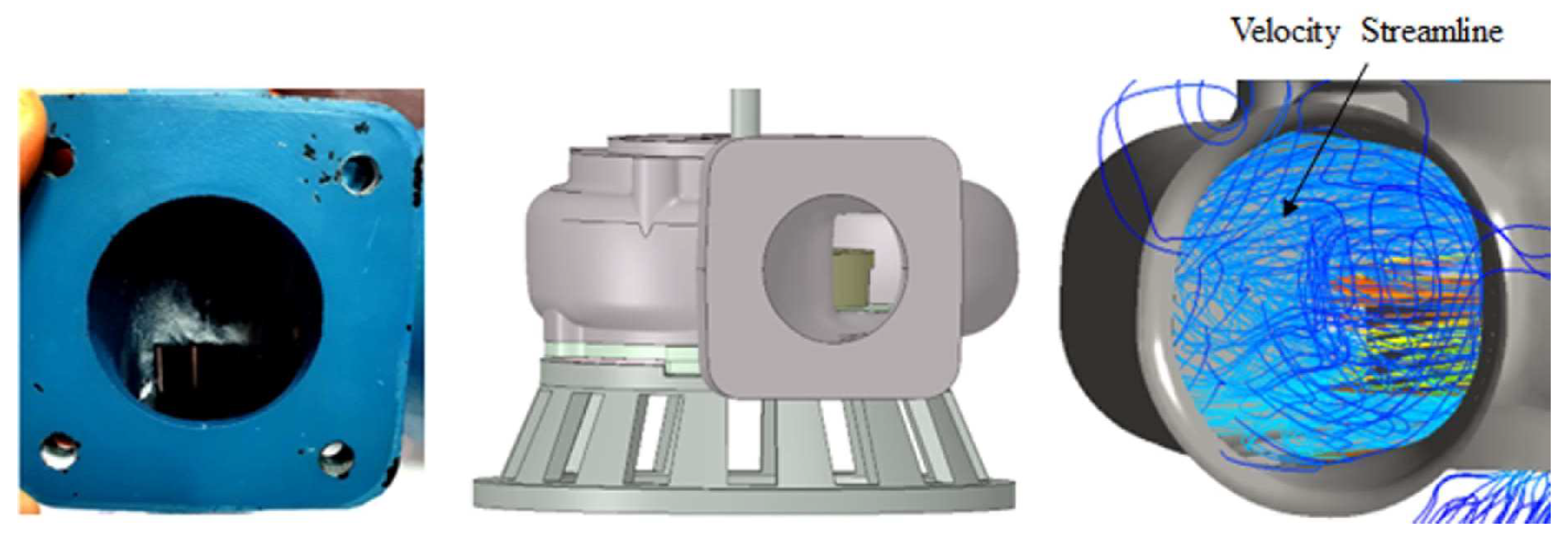
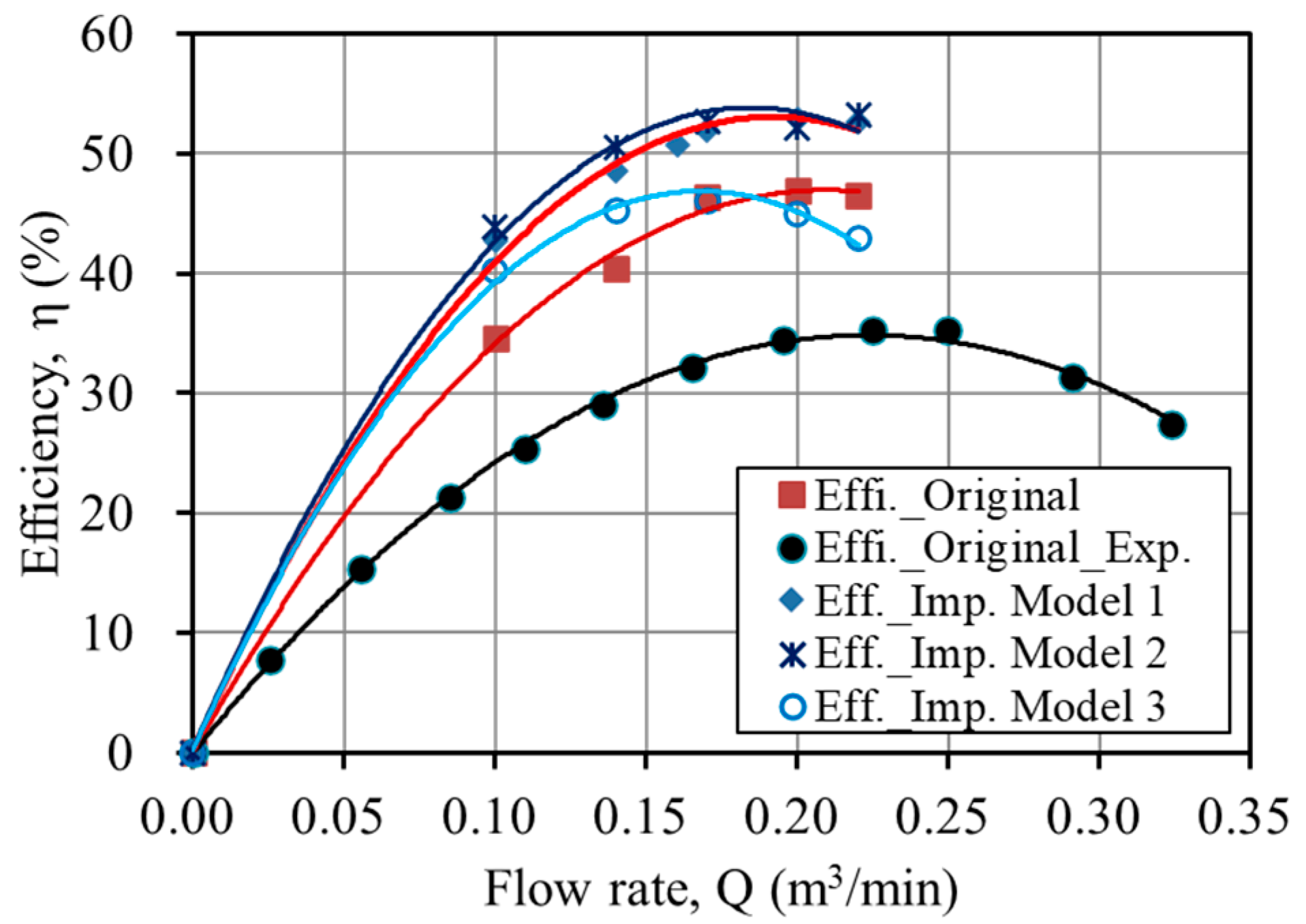
3.2. Performance Analysis

Additionally, this study analyzed the flow pattern inside the pump and velocity distributions at the design flow rate. Figure 9 shows the velocity vectors and velocity streamline distribution of the pump. As can be observed, the flow recirculates in the pump discharge region, where the energy dissipates, resulting in significant pump losses. The flow separation in the casing caused relatively large vortices at the outlet of the pump casing. Also, the clearance gap between the pump volute and impeller was large (more than 2 mm). This clearance gap flow creates vortices that separate from the impeller blade and reduce local pressure. Also, the impeller was located in the casing at the bottom of the pump, as shown in Figure 10. Henceforth, changing the impeller’s center further reduced the pump’s efficiency. Therefore, a CFD-based design modification study and research analyzing the behavior of the flow in various geometries are needed to enhance pump performance.
Based on the experimental and simulation results, we determined that there is a possibility of increasing efficiency by using an efficient pump motor and designing or shaping the part where the loss occurs. The use of an efficient pump motor was outside the scope of this study; this study examined the cause of the decrease in efficiency and found a way to supplement the design of the pump components. It was noted from the loss analysis of the pump that the mechanical loss, the ratio of impeller loss to casing, and inlet loss were also high [42]. The efficiency of the DWE-08B pump ranged from 30% to 40%, which is not an optimal performance condition. Of course, since the impeller was a semi-open type, it was less efficient than the closed type, but its efficiency was comparatively low compared with other pumps. Therefore, this study considered improving the efficiency to create the optimal design of the impeller and casing, suggesting improvements in the geometry of the two components.

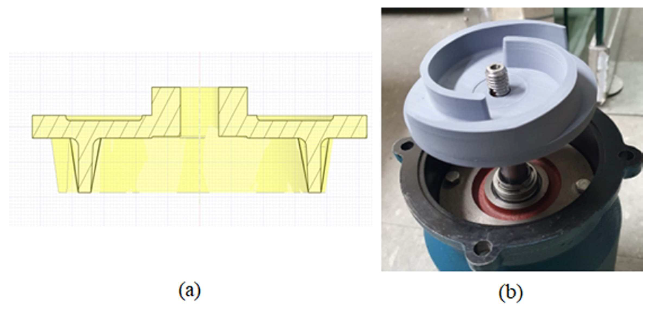
3.3. Design Modifications of the Casing and Impeller

In this study, two shapes that can reduce the large gap in the upper region of the pump impeller were proposed and analyzed to optimize the shape of the casing. Model 1 was created with a reduced flow path compared with the original model; model 2 was created with a cochlear (tubular) flow passage in the intact casing. Figure 11 shows the casing shape change model.
Figure 12 displays the comparison of velocity streamlines for the casing shape change model. As shown in Figure 12, the fluid flow formed a streamlined shape, eliminating the idle space at the top; the fluid flow at the outlet of the pump casing was discharged without swirling using a guide rib. Figure 13 shows the performance comparison for the casing shape change model. Table 4 presents the pump efficiency of the casing shape change models. By changing the casing shape, the relative efficiency was improved by up to 4~5%.
However, it is difficult to make a new one with die and casting; therefore, an in-depth investigation is a prerequisite for optimization. We applied the optimization plan of the casing shape to prevent the need for wood-shaped and casting work. One method involves attaching a simple installable member to the pump casing to reduce the space. Optimizing the casing shape utilizes an approach of changing the casing shape using a flow balance block (FBB), which can be easily installed. Here, we employed an FBB instead of the casing shape change model. Figure 14 shows the flow balance block model. We utilized an FBB to reduce secondary and friction losses where the flow in the casing was stagnant.
Also, we modified the three different shapes of the impeller. Impeller 1’s vanes were created diagonal (oblique line) in the basic model. Impeller 2 had an extended tip compared with Impeller model 1. Impeller model 3’s vanes were thicker compared with the vanes of the basic model. Figure 15 shows the impeller shape change model. The impeller shape change involved inclining the vane to improve the flow in front of the rear shroud. These pump simulation data were compared to assess the performance characteristics of the different impeller shapes to improve the efficiency of the original model.
Furthermore, Figure 16 illustrates the pressure and velocity streamline distribution in other planes of the pump impeller. As observed, the flow losses could be reduced by improving the streamline in the lower area (planes 1, 2) via a change in the impeller shape. Figure 17 shows the performance comparison of various impeller shape change models. The result shows that changing the shape of the impeller increased the pump efficiency. Hence, changing the impeller shape reduces the shaft power and increases the efficiency to 5.56% by preventing flow disturbance. Therefore, this study found the impeller shape change model 1 optimal for manufacturing.

3.4. Optimum Model

The existing model’s performance analysis and modification of the casing and impeller were reviewed. This study examined the flow around the impeller of the current model and devised a strategy to increase efficiency. The pump efficiency was significantly increased to 49.30%, less than 2.64% of that of the modified impeller, by modifying the casing shape at a 0.17 m3/min flow rate. Also, changing the impeller shape of the pump enhanced the internal pressure distribution and reduced the flow separation at the discharge side and its efficiency. The design flow rate of the pump was shifted from 0.16 m3/min to 0.17 m3/min.
Moreover, the efficiency increased to 5.56% at 0.17 m3/min, and the average efficiency increased to 6.27%. It is understood that changing the shape of the impeller and casing is the best solution to improving a pump’s performance [43]. Figure 18 shows the cross-sectional view of the original and newly designed impellers. Therefore, impeller shape change model 1 was considered optimal for manufacture.

4. Conclusions

Hydraulic performance optimization in a submersible pump was performed. A new pump impeller and flow balance block were designed, computational simulation was performed, parts were manufactured, and experiments were conducted. The results of this study on performance improvement are summarized as follows:
(a)
The test data verified the computed results, confirming the pump’s performance.
(b)
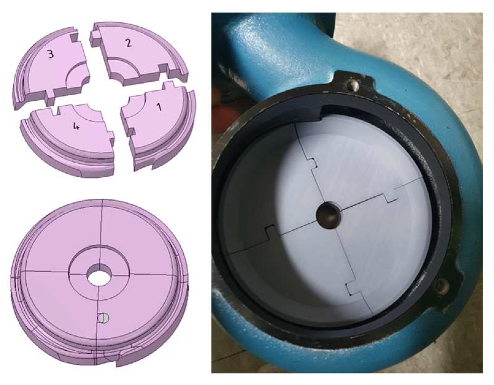
We modified the casing and impeller shape to improve hydraulic performance and used a flow balance block to reduce the inner space of the pump.
(c)
Changing the impeller shape reduced the power and increased efficiency, which can prevent flow disturbance. The attachment of the flow balance block increased the efficiency in the flow area more significantly than the operating point.
(d)
The flow separation inside the pump was significantly improved and increased pump performance by up to 5.56% at the design flow rate.
(e)
This research obtained two Korean patents based on the identified performance improvement results.
(f)
Further studies should consider conducting a performance test for the shape change model for a submersible pump.

5. Patents

Impeller for submersible pump (patent no.: 20-2021-0001433) and centrifugal submersible pump (patent no.: 10-2021-0058374). http://engpat.kipris.or.kr/engpat/searchLogina.do?next=MainSearch (17 November 2023).

Author Contributions

M.R. conceived and designed the study, analyzed the results, wrote the paper and edited the draft; S.-H.S. contributed to project administration and conceptualization and supervised the work; H.-W.R. managed resources, conducted the experiment and edited the draft; K.H.S. contributed to fund acquisitions and resources for the work; K.C.S. contributed to the experiment; and L.Z. advised on project work. All authors have read and agreed to the published version of the manuscript.

Funding

This research was funded by the Daeyoung Power Pump Co., Ltd., for the promotion of science.

Data Availability Statement

The study did not report any data.

Acknowledgments

This research was supported by Daeyoung Power Pump.

Conflicts of Interest

The authors declare no conflicts of interest.

References

  1. Dabade, S.P.; Gajendragadkar, J. Design, Modelling and CFD Analysis of Submersible Vertical Turbine Pump (Polder Pump). In Proceedings of the National Conference on Recent Trends in Mechanical Engineering, Sangli, India, 28–29 April 2016. [Google Scholar]
  2. Daeyoung Power Pump Catalog (DWE-Submersible Pump), Daeyoung Power Pump Co., Ltd., Korea. Available online: http://www.dypump.co.kr/eng/sub02/view.php?id=95&ca_id=50&page= (accessed on 8 May 2023).
  3. Takacs, G. Electrical Submersible Pumps Manual: Design, Operations and Maintenance; Gulf Professional Publishing: Burlington, MA, USA, 2009; ISBN 9781856175579. [Google Scholar]
  4. Suh, S.-H.; Rakibuzzaman; Kim, K.-W.; Kim, H.-H.; Yoon, I.S.; Cho, M.-T. A Study on Energy Saving Rate for Variable Speed Condition of Multistage Centrifugal Pump. J. Therm. Sci. 2015, 24, 566–573. [Google Scholar] [CrossRef]
  5. Kaya, D.; Yagmur, E.A.; Yigit, K.S.; Kilic, F.C.; Eren, A.S.; Celik, C. Energy Efficiency in Pumps. Energy Convers. Manag. 2008, 49, 1662–1673. [Google Scholar] [CrossRef]
  6. Goto, A.; Nohmi, M.; Sakurai, T.; Sogawa, Y. Hydrodynamic Design System for Pumps Based on 3-D CAD, CFD, and Inverse Design Method. J. Fluids Eng. Trans. ASME 2002, 124, 329–335. [Google Scholar] [CrossRef]
  7. Parrondo-Gayo, J.L.; González-Pérez, J.; Fernández-Francos, J. The Effect of the Operating Point on the Pressure Fluctuations at the Blade Passage Frequency in the Volute of a Centrifugal Pump. J. Fluids Eng. Trans. ASME 2002, 124, 784–790. [Google Scholar] [CrossRef]
  8. Shi, W.-D.; Lu, W.-G.; Wang, H.-L.; Li, Q.-F. Research on the Theory and Design Methods of the New Type Submersible Pump for Deep Well. In Proceedings of the ASME 2009 Fluids Engineering Division Summer Meeting, Vail, CO, USA, 2–6 August 2009; pp. 1–7. [Google Scholar]
  9. Zhu, J.; Zhang, J.; Zhu, H.; Zhang, H.Q. A Mechanistic Model to Predict Flow Pattern Transitions in Electrical Submersible Pump under Gassy Flow Condition. In Proceedings of the SPE Artificial Lift Conference and Exhibition—Americas, The Woodlands, TX, USA, 28–30 August 2018. [Google Scholar] [CrossRef]
  10. Manivannan, A. Computational Fluid Dynamics Analysis of a Mixed Flow Pump Impeller. Int. J. Eng. Sci. Technol. 2011, 2, 200–206. [Google Scholar] [CrossRef]
  11. Ragoth Singh, R.; Nataraj, M. Parametric Study and Optimization of Pump Impeller by Varying the Design Parameter Using Computational Fluid Dynamics. Int. Rev. Mech. Eng. 2012, 6, 1581–1585. [Google Scholar]
  12. Ajay, A.J.; Stephen, S.E.A.; Smart, D.S.R. Shape Optimization of Submersible Pump Impeller Design. In Proceedings of the 2017 First International Conference on Recent Advances in Aerospace Engineering (ICRAAE), Coimbatore, India, 3–4 March 2017; Volume 8, pp. 56–69. [Google Scholar] [CrossRef]
  13. Zangeneh, M.; Goto, A.; Takemura, T. Suppression of Secondary Flows in a Mixed-Flow Pump Impeller by Application of Three-Dimensional Inverse Design Method: Part 1-Design and Numerical Validation. ASME J. Turbomach. 1996, 118, 536–543. [Google Scholar] [CrossRef]
  14. Goto, A.; Takemura, T.; Zangeneh, M. Suppression of Secondary Flows in a Mixed-Flow Pump Impeller by Application of 3d Inverse Design Method: Part 2-Experimental Validation. In Proceedings of the ASME 1994 International Gas Turbine and Aeroengine Congress and Exposition, The Hague, Netherlands, 13–16 June 1994; Volume 1, pp. 536–543. [Google Scholar] [CrossRef]
  15. Kim, S.; Lee, K.Y.; Kim, J.H.; Choi, Y.S. A Numerical Study on the Improvement of Suction Performance and Hydraulic Efficiency for a Mixed-Flow Pump Impeller. Math. Probl. Eng. 2014, 2014, 269483. [Google Scholar] [CrossRef]
  16. Kim, S.; Kim, Y.I.; Kim, J.H.; Choi, Y.S. Design Optimization for Mixed-Flow Pump Impeller by Improved Suction Performance and Efficiency with Variables of Specific Speeds. J. Mech. Sci. Technol. 2020, 34, 2377–2389. [Google Scholar] [CrossRef]
  17. Yan, P.; Chu, N.; Wu, D.; Cao, L.; Yang, S.; Wu, P. Computational Fluid Dynamics- Based Pump Redesign to Improve Efficiency and Decrease Unsteady Radial Forces. J. Fluids Eng. Trans. ASME 2017, 139, 011101. [Google Scholar] [CrossRef]
  18. Baun, D.O.; Flack, R.D. Effects of Volute Design and Number of Impeller Blades on Lateral Impeller Forces and Hydraulic Performance. Int. J. Rotating Mach. 2003, 9, 145–152. [Google Scholar] [CrossRef]
  19. Wu, D.; Yan, P.; Chen, X.; Wu, P.; Yang, S. Effect of Trailing-Edge Modification of a Mixed-Flow Pump. J. Fluids Eng. Trans. ASME 2015, 137, 101205. [Google Scholar] [CrossRef]
  20. Qian, C.; Luo, X.; Yang, C.; Wang, B. Multistage Pump Axial Force Control and Hydraulic Performance Optimization Based on Response Surface Methodology. J. Brazilian Soc. Mech. Sci. Eng. 2021, 43, 136. [Google Scholar] [CrossRef]
  21. Liu, Z.M.; Gao, X.G.; Pan, Y.; Jiang, B. Multi-Objective Parameter Optimization of Submersible Well Pumps Based on RBF Neural Network and Particle Swarm Optimization. Appl. Sci. 2023, 13, 8772. [Google Scholar] [CrossRef]
  22. Bai, L.; Yang, Y.; Zhou, L.; Li, Y.; Xiao, Y.; Shi, W. Optimal Design and Performance Improvement of an Electric Submersible Pump Impeller Based on Taguchi Approach. Energy 2022, 252, 124032. [Google Scholar] [CrossRef]
  23. Chen, J.; Wang, M.; Bao, Y.; Chen, X.; Xia, H. Mixed-Flow Pump Performance Improvement Based on Circulation Method. Front. Energy Res. 2023, 11, 1177437. [Google Scholar] [CrossRef]
  24. Suh, J.W.; Yang, H.M.; Kim, Y.I.; Lee, K.Y.; Kim, J.H.; Joo, W.G.; Choi, Y.S. Multi-Objective Optimization of a High Efficiency and Suction Performance for Mixed-Flow Pump Impeller. Eng. Appl. Comput. Fluid Mech. 2019, 13, 744–762. [Google Scholar] [CrossRef]
  25. Jeon, S.Y.; Kim, C.K.; Lee, S.M.; Yoon, J.Y.; Jang, C.M. Performance Enhancement of a Pump Impeller Using Optimal Design Method. J. Therm. Sci. 2017, 26, 119–124. [Google Scholar] [CrossRef]
  26. Siddique, H.; Mrinal, K.R.; Samad, A. Optimization of a Centrifugal Pump Impeller by Controlling Blade Profile Parameters. In Proceedings of the ASME Turbo Expo 2016: Turbomachinery Technical Conference and Exposition, Seoul, South Korea, 13–17 June 2016; American Society of Mechanical Engineers: Seoul, South Korea, 2016; pp. 1–8. [Google Scholar]
  27. Shim, H.S.; Kim, K.Y.; Choi, Y.S. Three-Objective Optimization of a Centrifugal Pump to Reduce Flow Recirculation and Cavitation. J. Fluids Eng. Trans. ASME 2018, 140, 091202. [Google Scholar] [CrossRef]
  28. Yang, Y.; Zhou, L.; Hang, J.; Du, D.; Shi, W.; He, Z. Energy Characteristics and Optimal Design of Diffuser Meridian in an Electrical Submersible Pump. Renew. Energy 2021, 167, 718–727. [Google Scholar] [CrossRef]
  29. Arocena, V.M.; Abuan, B.E.; Reyes, J.G.T.; Rodgers, P.L.; Danao, L.A.M. Numerical Investigation of the Performance of a Submersible Pump: Prediction of Recirculation, Vortex Formation, and Swirl Resulting from off-Design Operating Conditions. Energies 2021, 14, 5082. [Google Scholar] [CrossRef]
  30. Wei, Y.; Yang, Y.; Zhou, L.; Jiang, L.; Shi, W.; Huang, G. Influence of Impeller Gap Drainage Width on the Performance of Low Specific Speed Centrifugal Pump. J. Mar. Sci. Eng. 2021, 9, 106. [Google Scholar] [CrossRef]
  31. Han, C.; Liu, J.; Yang, Y.; Chen, X. Influence of Blade Exit Angle on the Performance and Internal Flow Pattern of a High-Speed Electric Submersible Pump. Water 2023, 15, 2774. [Google Scholar] [CrossRef]
  32. Tong, Z.; Yuan, Y.; Zhang, C.; Zhang, Z.; Zhang, Y. Performance Analysis and Experimental Verification of Hydraulic Driven Axial Flow Pumps. J. Mech. Sci. Technol. 2023, 37, 2941–2947. [Google Scholar] [CrossRef]
  33. Fakher, S.; Khlaifat, A.; Nameer, H. Improving Electric Submersible Pumps Efficiency and Mean Time between Failure Using Permanent Magnet Motor. Upstream Oil Gas Technol. 2022, 9, 100074. [Google Scholar] [CrossRef]
  34. Zhu, J.; Zhu, H.; Zhang, J.; Zhang, H.Q. A Numerical Study on Flow Patterns inside an Electrical Submersible Pump (ESP) and Comparison with Visualization Experiments. J. Pet. Sci. Eng. 2019, 173, 339–350. [Google Scholar] [CrossRef]
  35. Kim, H.-H.; Rakibuzzaman, M.; Kim, K.; Suh, S.-H. Flow and Fast Fourier Transform Analyses for Tip Clearance Effect in an Operating Kaplan Turbine. Energies 2019, 12, 264. [Google Scholar] [CrossRef]
  36. Ansys Inc. ANSYS-CFX (CFX Introduction, CFX Reference Guide, CFX Tutorials, CFX-Pre User’s Guide, CFX-Solver Manager User’s Guide, Theory Guide), Release 21.00R2, USA 2021; Ansys Inc.: Bloomington, MN, USA, 2021. [Google Scholar]
  37. Anderson, D.A.; Tannehill, J.C.; Pletcher, R.H. Computational Fluid Mechanics and Heat Transfer; Taylor & Francis: Washington DC, USA, 1984. [Google Scholar]
  38. David, C. Wilcox Turbulence Modeling for CFD, 1st ed.; DCW Industries, Inc.: La Cañada Flintridge, CA, USA, 1994. [Google Scholar]
  39. Menter, F.R. Two-Equation Eddy-Viscosity Turbulence Models for Engineering Applications. AIAA J. 1994, 32, 1598–1605. [Google Scholar] [CrossRef]
  40. KS B 6301; Testing Methods for Centrifugal Pumps, Mixed Flow Pumps and Axial Flow Pumps, National Standard. Korean Standards Association: Seoul, Korea, 2015.
  41. ISO 5198; Centrifugal, Mixed Flow and Axial Pumps-Code for Hydraulic Performance Tests-Precision Class. International Standard: Geneva, Switzerland, 1987.
  42. Douglas, J.F.; Gasiorek, J.; Swaffield, J. Fluid Mechanics, 4th ed.; Prantise Hall: Upper Saddle River, NJ, USA, 2001. [Google Scholar]
  43. Rakibuzzaman, M.; Suh, S.H.; Kim, H.H.; Ryu, Y.; Kim, K.Y. Development of a Hydropower Turbine Using Seawater from a Fish Farm. Processes 2021, 9, 266. [Google Scholar] [CrossRef]
Figure 1. Disassembling the submersible drainage pump (DWE-08).
Computation 12 00012 g001
Figure 2. Assembly and disassembly drawing of the submersible drainage pump (DWE-08B) and different views.
Computation 12 00012 g002
Figure 3. Cross-sectional view of the pump’s key components.
Computation 12 00012 g003
Figure 4. Hydraulic performance curve of various submersible pumps [2].
Computation 12 00012 g004
Figure 5. Procedure for hydraulic performance optimization of the submersible drainage pump.
Computation 12 00012 g005
Figure 6. Submersible pump meshing grids used for computation.
Computation 12 00012 g006
Figure 7. Boundary conditions of the computational domain.
Computation 12 00012 g007
Figure 8. Performance comparison between the experiment and computational results for the submersible pump: (a) head vs. flow rate and (b) efficiency vs. flow rate (experimental uncertainty in N ± 3.298 rpm, Q ± 0.00178 m3/min, H ± 0.0989 m and P ± 0.0102 kW).
Computation 12 00012 g008
Figure 9. Velocity distributions analysis inside the casing: (a) velocity vectors; (b) velocity streamlines; (c) blade-to-blade velocity streamlines.
Computation 12 00012 g009
Figure 10. The position of the impeller inside the casing of the pump.
Computation 12 00012 g010
Figure 11. Casing shape change model: (a) original model; (b) model 1 (c) model 2.
Computation 12 00012 g011
Figure 12. Velocity streamline comparison for shape change model: (a) original model; (b) model 1; (c) model 2.
Computation 12 00012 g012
Figure 13. Performance comparison for casing shape change model.
Computation 12 00012 g013
Figure 14. Flow balance block model.
Computation 12 00012 g014
Figure 15. Impeller shape model 1.
Computation 12 00012 g015
Figure 16. Pressure and velocity streamline distribution in different planes: (a) original impeller; (b) impeller model 1.
Computation 12 00012 g016
Figure 17. Performance comparison of impeller shape change models.
Computation 12 00012 g017
Figure 18. Cross-sectional view of the optimum model: (a) impeller model 1; (b) manufactured model.
Computation 12 00012 g018
Table 1. Original submersible pump model (DWE-08B) design parameters.
DescriptionPowerFlow RateHeadImpellerCasing
BladesD1D2Flow Path HeightInlet HeightOutlet Dia.
ModelH.P.m3/minmNo.mmmmmmmmmm
DWE-08B10.16102251055413560
Table 2. Submersible pump performance data [2].
ModelOutlet Height (mm)Power (H.P.)Flow Rate (m3/min)Head (m)
DWE-08B5010.1610
Table 3. Meshing grids of the DWE-08 submersible pump.
DescriptionElementsNodesHead (m)Relative Error (%)
Model 1205,9621,241,3659.824-
Model 2272,5631,374,8299.8710.47842
Model 3532,9242,733,3199.8530.18235
Model 41,085,6835,648,7309.8160.37552
Table 4. Comparison of pump efficiency for casing shape change model.
Flow Rate
(m3/min)
Original (%)Model 1 (%)Model 2 (%)Efficiency Improvement (%)
Model 1Model 2
0.1034.59340.54238.9045.9494.311
0.1440.42048.35845.4747.9385.054
0.1645.41550.68749.2305.2723.815
0.1746.37551.51349.3015.1382.926
0.2046.92152.82652.3575.9055.436
0.2246.56253.48752.2216.9255.659
Disclaimer/Publisher’s Note: The statements, opinions and data contained in all publications are solely those of the individual author(s) and contributor(s) and not of MDPI and/or the editor(s). MDPI and/or the editor(s) disclaim responsibility for any injury to people or property resulting from any ideas, methods, instructions or products referred to in the content.

