Article

Optimized Packing Titanium Alloy Powder Particles

1
Department of Materials Science and Engineering, Lviv Polytechnic National University, 12 Bandera St., 79013 Lviv, Ukraine
2
Department of Natural Sciences and Technology, Institute of Engineering and Sciences, Katolicki Uniwersytet Lubelski Jana Pawła II, Al. Racławickie 14, 20-950 Lublin, Poland
3
Department of Mathematical Modelling and Optimal Design, Institute for Mechanical Engineering Problems of the National Academy of Sciences of Ukraine, Pozharskogo St., 2/10, 61046 Kharkiv, Ukraine
4
Department of Systems Engineering, Kharkiv National University of Radioelectronics, 14 Nauky Ave., 61166 Kharkiv, Ukraine
5
Graduate Program in Systems Engineering, Nuevo Leon State University (UANL), Av. Universidad s/n, Col. Ciudad Universitaria, San Nicolas de los Garza 66455, Nuevo Leon, Mexico
6
Faculty of Business, University of Leeds, Maurice Keyworth Building, Leeds LS2 9JT, UK
*
Author to whom correspondence should be addressed.
Computation 2023, 11(2), 22; https://doi.org/10.3390/computation11020022
Submission received: 18 December 2022 / Revised: 26 January 2023 / Accepted: 30 January 2023 / Published: 1 February 2023
(This article belongs to the Special Issue Intelligent Computing, Modeling and its Applications)

Abstract

:
To obtain high-quality and durable parts by 3D printing, specific characteristics (porosity and proportion of various sizes of particles) in the mixture used for printing or sintering must be assured. To predict these characteristics, a mathematical model of optimized packing polyhedral objects (particles of titanium alloys) in a cuboidal container is presented, and a solution algorithm is developed. Numerical experiments demonstrate that the results obtained by the algorithm are very close to experimental findings. This justifies using numerical simulation instead of expensive experimentation.

1. Introduction

Additive manufacturing is important in economy, medicine, industry, and education. Many challenging issues in energy and material saving, as well as important environmental problems, can be solved using additive manufacturing [1,2]. Using a 3D printer, physical objects can be created based on their three-dimensional images [3]. Additive technologies are widely used in industrial production, medical and aerospace industries [4].
State-of-the-art laser 3D printers can work with different materials: Polymers, ceramics, organics, etc. [4]. However, most industrial technologies use metal powders as consumables. Metal raw materials are subjected to the sintering process (or completely melted), which allows obtaining a variety of products, from specialized precision parts to models, prototypes, or jewelry. During sintering, the metal powder is partially melted so that the particles can merge with each other [4].
Materials, such as titanium, titanium alloys, steel, stainless steel, aluminum, copper, nickel alloys, and superalloys, can be used as powder raw materials [5]. Some high-value metals are also available in powder form. Among all these materials, the most promising for industrial purposes are powders of titanium and nickel alloys, which are characterized by high strength and corrosion resistance while low density [5].
There are two main technologies for producing metal powder parts by additive manufacturing: Bed deposition and direct deposition [4]. In this paper, we focus on the first technique based on fixing (melting, sintering) the previous layer of powder and supply of already sintered powder layer by layer to obtain a product in accordance with the developed CAD model.
After layer-by-layer build-up, metal powders in the microstructure become close to equilibrium, and some annealing or aging effect may arise caused by the low cooling rate [1].
The high porosity of the finished products during the 3D printing process leads to decreasing their mechanical properties [6]. The packing density influences the ability of powder sintering. Optimization of the particle size distribution before sintering is important in the process of 3D printing when the microstructure is subject to certain requirements, such as a combination of fraction sizes and a microstructure of individual particles [1,4]. Thus, a certain proportion between the particle characteristics must be maintained to reduce the porosity.
To get a quality product (or 3D part), the shapes of particles, as well as their size distribution, must be controlled to optimize the technological process of obtaining metal powders. This enables eliminating defects on the product surface.
Recently, the use of various alloys based on zirconium and titanium powders incremented significantly [7,8]. An important stage in the formation of high-quality parts is the assessment of the chemical, phase, and fractional composition of the powder mixture. To control the configuration of individual powder particles, the specific correspondence between various sizes fractions and the porosity of the prepared mixture for printing or sintering is important. This can be done by physical, mathematical, and computer modeling. After all, to solve material science and technological issues, one should simultaneously optimize the filling of a given volume for powder particles of different shapes and sizes.
The proposed multidisciplinary study uses smart technologies for controlling the technological processes of 3D printing and monitoring the degradation of the microstructure [9,10,11,12,13,14].
The aim of this work is to develop an approach to modeling layer-by-layer filling of a certain 3D volume (container) with non-spherical (polyhedral) particles. A fast heuristic is proposed for solving the packing problem. Experimental findings for titanium alloys and computational results for polyhedral particles are compared. The close results permit using cheap numerical simulations instead of expensive experimental studies.
The novelty of the paper involves four main contributions:
  • Optimizing characteristics of titanium alloys used for 3D printing.
  • Nonlinear programming model for filling a working volume with polyhedral particles.
  • Fast solution approach based on a flexible active layer strategy.
  • Comparing numerical and experimental findings.
The paper is organized as follows. A general formulation for packing convex polyhedral in a cuboidal container is presented in Section 2. The corresponding nonlinear programming problem is formulated in Section 3 using the phi-functions approach. A heuristic solution scheme is highlighted in Section 4. Numerical indicators are provided in Section 5, and Section 6 presents concluding remarks.

2. Formulation of the Packing Problem

Let Ω = { ( x , y , z ) : 0 x l , 0 y w , 0 z h } be a cuboidal container (a model of given volume). As models of non-spherical particles, a set of convex polyhedra K i , i I N = { 1 , 2 , , N } is given. Assume that u i = ( v i , θ i ) denotes the variable motion vector (placement parameters) of K i , where θ i = ( θ i 1 , θ i 2 , θ i 3 ) , θ i 1 , θ i 2 , θ i 3 are Euler angles.
The motion of each polyhedron K is denoted by K ( u ) = { p R 3 : p = v + M ( θ ) · p 0 ,   p 0 K } where K is non-rotated and non-translated polyhedron, M ( θ )   is a rotation matrix of the form:
cos θ 1 cos θ 3 sin θ 1 cos θ 2 sin θ 3 cos θ 1 sin θ 3 sin θ 1 cos θ 2 cos θ 3 sin θ 1 sin θ 2 sin θ 1 cos θ 3 + cos θ 1 cos θ 2 sin θ 3 sin θ 1 sin θ 3 + cos θ 1 cos θ 2 cos θ 3 cos θ 1 sin θ 2 sin θ 2 sin θ 3 sin θ 2 cos θ 3 cos θ 2
A problem of filling a certain 3D volume (container Ω) with non-spherical (polyhedral) particles can be stated as an optimization packing problem as follows.
Let L be the number of given types (shapes) t 1 , t 2 , , t L of polyhedra with M gradations of the average Ferret diameter r 1 , r 2 , , r M for each type. Therefore, we associate with each polyhedron K i an appropriate type T i { t 1 , t 2 , , t L } of the average Ferret diameter (a measure of particle size), denoted by R i { r 1 , r 2 , , r M } .
The number N of polyhedra that must be completely arranged into Ω is unknown, therefore, we assume that N = V Ω / V ˜ . Here, V ˜   is the minimum volume of objects to be placed.
The statistic probabilities p 1 , p 2 , , p M of the appearance of the average Fere diameters are given, where p m = (the number of packed polyhedra of radius   r m )/(a total number of packed polyhedra) m = 1 M p m = 1 and statistical probabilities f 1 , f 2 , , f L   of object type occurrence, where f l = (the number of packed polyhedra of type t l )/(a total number of packed polyhedra), l = 1 L f l = 1 . Here, numerators and denominators are determined using fragments of the test filling of the cuboid found experimentally.
We need to pack a set of polyhedra K i , i I N minimizing the volume of a cuboidal container Ω subject to the following placement conditions:
Pairwise non-overlapping of objects, i.e., int   K i ( u i ) int K j ( u j ) = , i > j I N , and containment of each object in the container Ω of variable sizes l , w , h , i.e., K i ( u i ) Ω ( l , w , h ) , i I N meeting statistical probabilities f 1 , f 2 , , f L of the appropriate object type occurrence.
This problem is aimed at modeling the filling of the container Ω with polyhedra K i of type T i   of the average Ferret diameter R i , i I N by “pouring” the polyhedral particles down to the axis OZ into the container Ω, while calculating the packing factor (the inverse of the porosity).
Many publications address packing non-spherical shapes (see [15,16,17] and corresponding references). The approach presented in the next section permits formulating the packing problem in the form of a nonlinear optimization problem. We use the phi-function technique for the arrangement of non-spherical particles (polyhedra) in the container, considering their continuous rotations [18,19,20,21].

3. Geometric Tools and Mathematical Model

We use a quasi-phi-function for two convex polyhedra K i ( u i ) and K j ( u j ) for describing non-overlapping of particles.
Let convex polygons K i ( u i ) and K j ( u j ) be given by their vertices p k i ,   k = 1 , , m i , and p l j ,   l = 1 , , m j . Let P ( u P ) = { ( x , y , z ) : ψ P = α x + β y + γ z + μ P 0 } be a half-space, α = sin θ P 1 sin θ P 2 ,   β = cos θ P 1 sin θ P 2 , γ = cos θ P 2 . Here θ P 1 and θ P 2 are the corresponding variable Euler angles (while θ P 3 = 0 ).
A quasi-phi-function Φ i j ( u i , u j , u i j = u P ) for convex polyhedra K i ( u i ) and K j ( u g ) can be defined in the form:
Φ i j ( u i , u j , u P ) = min { Φ K i P ( u i , u P ) , Φ K j P * ( u j , u P ) }  
where Φ K i P ( u i , u P ) is the phi-function for the polyhedron K i ( u i ) and the halfspace P ( u P ) , Φ K j P * ( u j , u P ) is the phi-function for the polyhedron K j ( u j ) and the halfspace P * ( u P ) = R 3 \ int P ( u P ) , int P ( u P ) is the interior of P ( u P ) , u P = ( θ P 1 , θ P 2 , μ P ) , Φ K i P ( u i , u P ) = m i n 1 k m i ψ P ( p k i ) ,   Φ K j P * ( u j , u P ) = m i n 1 l m j ( ψ P ( p l j ) ) .
If Φ K i K j ( u i , u j , u P ) > 0 then L P = { ( x , y , z ) : ψ P ( u P ) = 0 } is a separating plane for convex polyhedra K i ( u i ) and K j ( u j ) .
Thus, if int K i ( u i ) int   K j ( u j ) = , then there exists a vector u P = ( θ P 1 , θ P 2 , μ P ) , such that m a x u P Φ i j ( u i , u j , u P ) > 0 .
Therefore, Φ i j ( u i , u j , u P ) 0   for   some   u P   implies   int K i ( u i ) int K j ( u j ) = .
Let us describe the containment constraint, K i ( u i ) Ω int K i ( u i ) Ω * = .
Denote vertices of a convex polyhedron K i ( u i ) by   p k i ,   k = 1 , , m i , p k i = ( p x k i , p y k i , p z k i ) .
A phi-function for K i ( u i ) and the container Ω * can be defined in the following form:
Φ K i Ω * ( l , w , h , u i ) = min { m i n 1 k m i φ k i j ( l , w , h , u i ) , j = 1 , , 6 } ,  
φ k i 1 ( u i , l , w , h , ) = x i + p x k i ,   φ k i 2 ( u i , l , w , h , ) = ( x i + p x k i ) + l
φ k i 3 ( u i , l , w , h ) = y i + p y k i ,   φ k i 4 ( u i , l , w , h , ) = ( y i + p y k i ) + w
φ k i 5 ( u i , l , w , h , ) = z i + p z k i ,   φ k i 6 ( u i , l , w , h , ) = ( z i + p z k i ) + h
Using continuous functions (1), (2), a mathematical model of the polyhedral packing problem can be stated in the form:
min κ ( u )
subject to:
Φ i j ( u i , u j , u i j ) 0 , ( i , j ) I N × I N , i < j , Φ i ( u i , l , w , h ) 0 , i I N
where u R σ is a vector of all variables; σ = 3 + 6 N + 3 N ( N 1 ) / 2 is the number of the problem variables; u = ( ς , τ ) R σ ,   ς = ( u 1 , , u N , l , w , h , ) ; l , w , h are variable metrical characteristics of cuboid Ω ; u i = ( v i , θ i ) is a variable motion vector of K i ( u i ) ; τ = ( u 1 , , u m ) is a vector of auxiliary variables; u s = ( θ P 1 s , θ P 2 s , μ P s ) , s = 1 , , m ,   m = 3 N ( N 1 ) / 2 ; κ ( u ) = l w h , Φ i j is a quasi-phi-function (1) for K i ( u i ) and K j ( u j ) ; Φ i is a phi-function (2) for K i ( u i ) and Ω * ( l , w , h ) .

4. Solution Approach

The non-spherical particle packing algorithm is a modification of the spherical particle packing algorithm [22]. In practice, millions of polyhedral particles are used for filling a given volume to define the correspondence between the cuboid dimensions and the average Fere diameters of polyhedra. Taking into account the additive production, all filling operations should be performed in the upper layer of the container, which is referred to as an active layer. The placement of non-overlapping polyhedra is controlled in the active layer only. The height of the active layer is iteratively updated to the current data. This way, the simulation time can be reduced significantly.
The following iterative algorithm simulates filling the cuboid with different shapes and sizes of polyhedra. The active level parameters are updated in each iteration of the procedure.

4.1. The Principal Steps of the Approach

  • Step 1. “Normalizing” objects and the container Ω.
  • Define
    r = ( r 1 , r 2 , , r M ) = ( r 1 r , r 2 r , , r M r ) ,   L = l r ,   W = w r ,   H = h r ,   r = 1 M m = 1 M r m p m , M = m = 1 M r m
  • Next, consider packing polyhedra of type T i { t 1 , t 2 , , t L } associated with the appropriate radii R i { r 1 , r 2 , , r M } into a cuboid of sizes L × W × H .
  • Step 2. Set i = 2 , j 0 = 1 , h m a x , Δ = 4 max { r 1 , r 2 , , r M } . Define P = ( P 1 , P 2 , , P M ) , P m = j = 1 m p j , m = 1 , 2 , , M . Set F = ( F 1 , F 2 , , F L ) , where F l = j = 1 l f j .
  • Step 3. Randomly generate the radius R 1 (see algorithm Q) associated with the polyhedron K 1 of type T 1 (see algorithm G).
  • Step 4. Place the center of the polyhedron K 1 at a point ( x 1 , y 1 , z 1 ) , where   x 1 [ R 1 , L R 1 ] ,   y 1 [ R 1 , W R 1 ] ,   z 1 = R 1 . Assume Euler angles are random variables.
  • Step 5. Create the arrangement of the object with the center at a random point ( x i 0 , y i 0 , z i 0 ) in a cuboid with dimensions L × W × ( H + 2 R i ) , providing non-overlapping with already packed polyhedra (algorithm S). If a feasible point cannot be found, then go to step 9.
    Step 6. Solve the nonlinear programming problem to search for the minimum of z c i   (coordinate of the gravity center of the polyhedron K i ):
    min ( z c i ) ,   s . t .   ( u i , u ) V i
    V i = { ( u i , u i j ) R σ | Φ i j ( u i , u j , u i j ) 0 ,
    Φ K i Ω * ( u i ) 0 , z i > z m i n , j = j 0 , j 0 + 1 , , i 1 }
    where u i = ( x i , y i , z i , θ i ) , θ i = θ i 1 , θ i 2 , θ i 3 , Φ i j ( u i , u j , u i j ) is the quasi-phi-function (3) for fixed  u j , Φ K i Ω * ( u i ) is the phi-function (4), σ = 6 + 2 ( i j 0 )   z m i n (algorithm S). The corresponding optimal solution ( x i 0 , y i 0 , z i 0 , θ i 0 , u i j 0 )   gives the appropriate placement parameters of the polyhedron K i and is considered as the initial point for the algorithm D below.
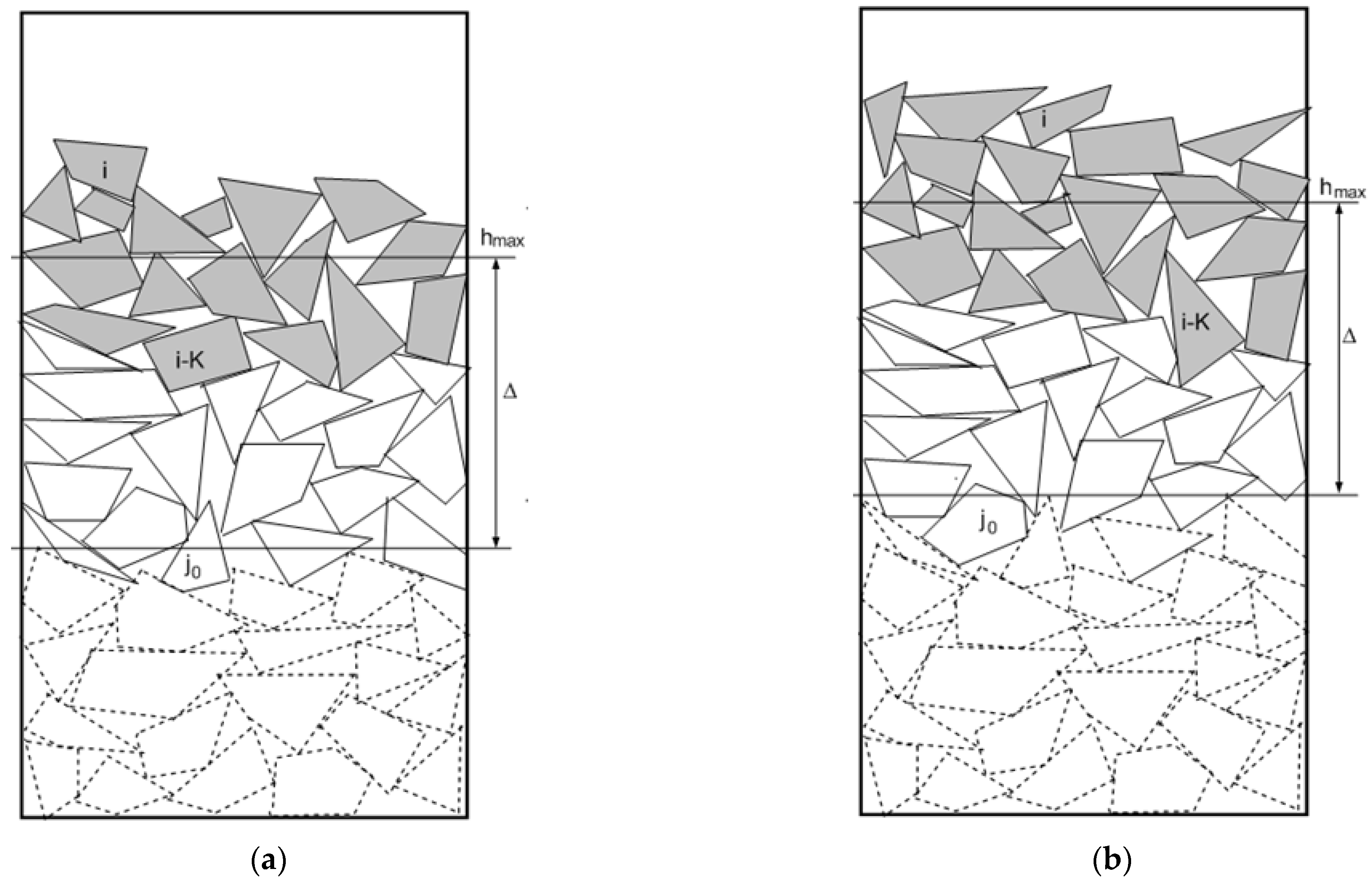
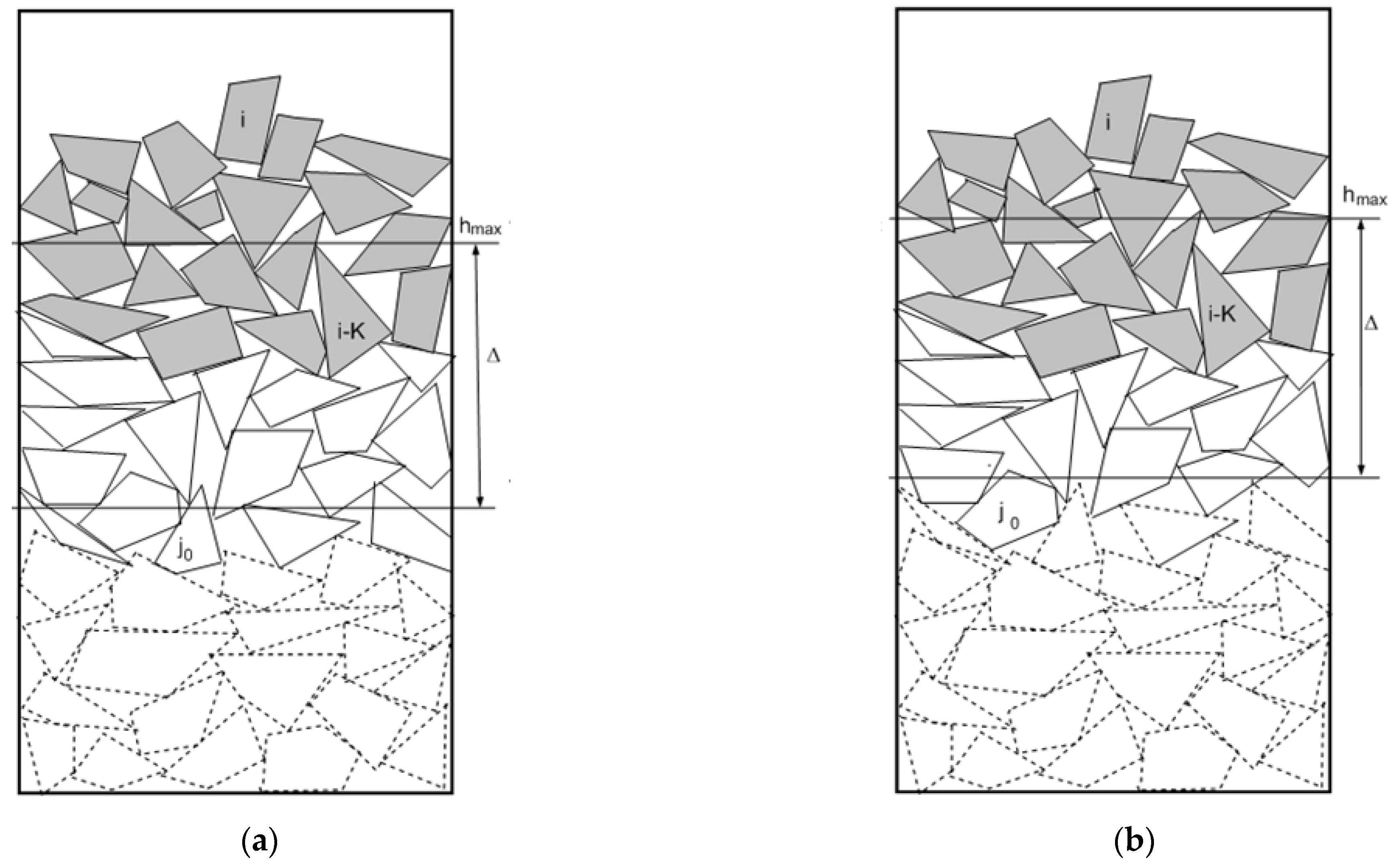
  • Step 7. Updating the size of the active layer:
    • Change the thickness of the active layer: if z i = h max + R i Δ then define Δ = 1.1 × Δ (increasing the thickness if the lower limit of the active layer is attained) and set j 0 = j 0 1 , while j 0 > 1 and z j 0 h m a x R j 0 Δ (see Figure 1);
    • Set H = 1000 (the maximal height of the active layer). If z i > H then set h max = h max + z i H H , otherwise set h max = h max + z i H to determine the upper bound of the active layer.
    • Polyhedra that are arranged under the active layer are not considered: set j 0 = j 0 + 1 for z j 0 < h max R j 0 Δ (Figure 2).
  • Step 8. If i < N , set i = i + 1 and go to step 4, otherwise, go to step 9.
  • Step 9. Recalculate corresponding coordinates for the centers of polyhedra, multiplying them by r while updating the original size of the polyhedra and the cuboid.
  • Step 10. Delete from the set of polyhedra that are not completely packed in a cuboid with dimensions l × w × h .

4.2. Description of Algorithms Q, G, S, and D Used in This Optimization Procedure

In the subsection, we provide a brief description of algorithms Q, G, S, and D used in this optimization procedure.
  • Algorithm Q. Generating a discrete value of the radius R depending on vectors r and P.
  • Step Q1. Find random value of p [ 0 , 1 ] .
  • Step Q2. Find the minimum index m for which p P m .
  • Step Q3. Set R = r m .
  • Algorithm G. Generating a discrete value of the type T with distribution law defined by vectors t   and F.
  • Step G1. Find random value of f [ 0 , 1 ] .
  • Step G2. Find the minimum index m for which f F m .
  • Step G3. Set T = t m .
  • Algorithm S. Generating a feasible packing of polyhedra (with radius R) of the active layer of the cuboid with size L × W × ( H + 2 R ) subject to i already packed polyhedra.
  • Step S1. Select g [ 1 , 100 ] to determine the “gravity” that affects the particles and define z m i n = H + 2 R .
  • Step S2. Set k = 1 , z m i n = 9999999 (a large number) and fix the angles of rotation of the object.
  • Step S3. Form and fix randomly chosen values of variables x i [ R , L R ] , y i [ R , W R ] .
  • Step S4. Define an index set
    Ξ = { j : j = j 0 , j 0 + 1 , , i 1 , | x i x j | < R i + R j , | y i y j | < R i + R j }
  • Step S5. Solve the nonlinear programming problem
    min ( z i ) ,   s . t .   ( z i , u i j ) V i V i = { ( z i , u ij ) R 1 + 3 q | Φ i j ( u i , u j , u i j ) 0 , ( i , j ) Ξ , z max ( z ki , z min ) }
    where   Φ i j ( u i , u j , u i j ) is the quasi-phi-function of the form (2) provided that   x i , y i , θ i , u j are fixed, q is the cardinality of the set Ξ .
  • Step S6. If z min > z i then set x min = x max ,   y min = y max ,   z min = z max .
  • Step S7. Set k = k + 1 . If k > g , then terminate algorithm S, otherwise go to step S2.
  • The output of algorithm S is a point ( x min , y min , z min , θ i ) .
  • If z min > H + R , then the current polyhedron cannot be placed in a cuboid with dimensions L × W × ( H + 2 R ) .
  • Algorithm D. Finding the minimal value of the z-th coordinate of a polyhedron using   ( x 0 , y 0 , z 0 , θ 0 ) as a starting feasible point.
  • Step D1. Set k = 0 and perform the decomposition step δ = 2 for the problem with normalized dimensions of the polyhedron.
  • Step D2. Define
    Ξ k = { j : j = j 0 , j 0 + 1 , , i 1 , | x x j | < R i + R j + δ , | y y j | < R i + R j + δ }
  • Step D3. Obtain the zth-coordinate of the i-th polyhedron by solving the following nonlinear programming problem:
    m i n ( z c i ) ,   s . t .   ( u i , u i j ) V i k V i k = { ( u i , u i j ) R 6 + 3 q |   Φ   i j ( u i , u j , u i j ) 0 , ( i , j ) Ξ k Φ K i Ω * ( u i ) 0 , z i > z m i n , j = j 0 , j 0 + 1 , , i 1 }
    where u i = ( x i , y i , z i , θ i ) , θ i = ( θ i 1 , θ i 2 , θ i 3 ) ,   Φ   i j is the quasi-phi-function (1), provided that the vector u j = ( x j , y j , z j , θ j ) is fixed, Φ K i Ω *   is the phi-function (2), q is the cardinality of the set Ξ k .
  • Take ( x i k , y i k , z i k ,   θ i k , u i j k ) as a starting point.
  • Step D4. Find a vector of coordinates ( x k + 1 , y k + 1 , z k + 1 ) of the center of the polyhedra.
  • Step D5. If z k + 1 = z k , then algorithm D is terminated, otherwise, set k = k + 1 and go to step D2.

5. Computational Results and Comparison with Experimental Findings

Computational results found by our algorithm and compared with experimental findings are considered in this section. We used AMD FX(tm)-6100, 3.30 GHz computer, Programming Language C++, Windows 7. The open solver IPOPT [23] was used for local optimization under default options.
The study was performed for powders of titanium alloys VT20 with particle sizes from 100 to 300 μm. The corresponding chemical composition (in %) was as follows: 88.9Ti, 6.5Al, 0.3Fe, 0.1C, 0.15Si, 1.0Mo, 0.8V, 0.05N, 0.7Zr, 0.5 impurities.
The sieve method was used to get powder fractions with a small variance of particle sizes (Figure 3). Metallographic analysis demonstrates that (after the hydrogenation-dehydrogenation process) the powder particles have non-spherical shapes and similar sizes.
To get a quality product, the parameters of powders of titanium alloys must be optimized. In particular, the powder particles must be maximally homogeneous.
The sizes of the particles in titanium alloy powder VT20 were analyzed by the image analysis software ImageJ [24,25]. Corresponding results are presented in Figure 4.
Distribution histograms for powder particles of the alloy BT20 show that in the fraction 200–250 μm, dominant particles have an average diameter 226 μm, while for the fraction 160–200 μm, the dominant diameter is 177 μm, and for 100–160 μm—114 μm, respectively.
As can be seen from Figure 4, decreasing the average particle size of the powder within a certain fraction results in increasing the scatter of sizes relative to this value of other particles.
Numerical results are presented in Table 1. Here, columns 3 and 4 present distributions of sizes of particles, absolute and percentage, while Ferret diameters corresponding to each fraction are presented in column 2. From Table 1, we may conclude that the fractions of the powder are well homogeneous for use in 3D printing processes.
Table 2 presents results obtained by the proposed algorithm for powder filling into a cuboid with ( l , w , h ) = ( 2000 , 2000 , 2000 ) compared with experimental results. The experimental results correspond to the bulk packing density of VT20 alloy powder particles [26]. For each fraction, the filling factor was defined as the ratio (total volume of packed polyhedra)/(container volume). As can be seen from Table 2, the difference between the algorithmic results and the experimental findings is less than 5%. The arrangement of particles calculated by the algorithm for 13 h 24 m, 18 h 35 m, and 27 h 41 m are presented in Figure 5, Figure 6 and Figure 7, correspondingly.
We may conclude that the proposed approach is reliable and can be applied to estimate the density (inverse of the porosity) for powders with different fractional compositions. Thus, cheaper numerical simulations can be used instead of expensive experimental research.

6. Conclusions

The size of fractions for non-spherical powders in VT20 titanium alloy is important to reduce defects in built-up layers. The surface morphology of VT20 alloy powder with different fractional compositions is studied. In contrast to traditional DEM methods used for analyses of granular structures [27,28,29,30], here, an optimization approach was applied. The results of the algorithm demonstrate that the built-up layers of non-spherical powders of Fraction 1 (200–250 microns) of VT20 titanium alloy have the best micromechanical properties. To avoid nonlinear optimization problems, simple grid approximations [31,32] can be considered to linearize optimized packing problems. The proposed models and algorithm can also be used for other alloys, such as stainless steels and superalloys, subject to adjusting the corresponding input parameters.
In this paper, non-spherical shapes of the alloy powder particles were studied. Compared with pure spherical shapes, considering convex polyhedral particles provides a more realistic approximation of real shapes and gives novel modeling opportunities. However, to make analyses of granular structures more realistic, more sophisticated shapes must be introduced. Considering irregular, non-convex, or convex-composed shapes is an interesting area for future research. Some results in this direction are on the way. The proposed modeling and algorithmic approach can also be used for ceramic materials [33,34]. Testing the approach for ceramics based on zirconium oxide modified with yttrium oxide is planned in the near future.

Author Contributions

Conceptualization, Z.D., T.R. and I.L. (Igor Litvinchev); methodology, A.P. and J.B.; software, A.P., I.L. (Igor Lemishka) and S.M.; validation, Z.D. and A.P.; formal analysis, T.R. and I.L. (Igor Litvinchev); investigation, T.R., I.L. (Igor Litvinchev) and J.B.; resources, I.L. (Igor Litvinchev) and J.B.; data curation, Z.D., A.P. and S.M.; writing—original draft preparation, Z.D., T.R. and I.L. (Igor Litvinchev); writing—review and editing, T.R. and I.L. (Igor Litvinchev); visualization, A.P., S.M.; supervision, T.R. and I.L. (Igor Litvinchev); project administration, T.R.; funding acquisition, T.R. and I.L. (Igor Litvinchev). All authors have read and agreed to the published version of the manuscript.

Funding

This research received no external funding.

Data Availability Statement

The data presented in this study are available on request from the corresponding author.

Acknowledgments

Tetyana Romanova was supported by Volkswagen Foundation under grant # 97775, 9C086, grant # 02.2020/167 of the National Research Foundation of Ukraine.

Conflicts of Interest

The authors declare no conflict of interest.

References

  1. Gibson, I.; Rosen, D.; Stucker, B. Additive Manufacturing Technologies, 1st ed.; Springer: New York, NY, USA, 2010. [Google Scholar] [CrossRef]
  2. Romanova, T.; Stoyan, Y.; Pankratov, A.; Litvinchev, I.; Avramov, K.; Chernobryvko, M.; Yanchevskyi, I.; Mozgova, I.; Bennell, J. Optimal layout of ellipses and its application for additive manufacturing. Int. J. Prod. Res. 2019, 59, 560–575. [Google Scholar] [CrossRef]
  3. Milewski, J.O. Additive Manufacturing of Metals, 1st ed.; Springer: New York, NY, USA, 2017. [Google Scholar] [CrossRef]
  4. Gibson, I.; Rosen, D.; Stucker, B.; Khorasani, M. Additive Manufacturing Technologies, 3rd ed.; Springer: New York, NY, USA, 2021. [Google Scholar]
  5. Qian, M.; Froes, F.H. Titanium Powder Metallurgy: Science, Technology and Applications; Butterworth-Heinemann: Oxford, UK, 2015. [Google Scholar]
  6. Duriagina, Z.A.; Lemishka, I.A.; Trostianchyn, A.M.; Kulyk, V.V.; Shvachko, S.G.; Tepla, T.L.; Pleshakov, E.I.; Kovbasyuk, T.M. The Effect of Morphology and Particle-Size Distribution of VT20 Titanium Alloy Powders on the Mechanical Properties of Deposited Coatings. Sov. Powder Met. Met. Ceram. 2019, 57, 697–702. [Google Scholar] [CrossRef]
  7. Duriagina, Z.; Holyaka, R.; Tepla, T.; Kulyk, V.; Arras, P.; Eyngorn, E. Identification of Fe3O4 Nanoparticles Biomedical Purpose by Magnetometric Methods; InTech: Rijeka, Croatia, 2018; Chapter 17. [Google Scholar] [CrossRef]
  8. Izonin, I.; Trostianchyn, A.; Duriagina, Z.; Tkachenko, Z.; Tepla, R.; Lotoshynska, T.N. The combined use of the wiener poly-nomial and SVM for material classification task in medical implants production. Int. J. Intell. Syst. Appl. 2018, 10, 40–47. [Google Scholar]
  9. Tepla, T.; Izonin, I.; Duriagina, Z.; Tkachenko, R.; Trostianchyn, A.; Lemishka, I.; Kulyk, V.; Kovbasyuk, T. Alloys selection based on the supervised learning technique for design of biocompatible medical materials. Arch. Mater. Sci. Eng. 2018, 1, 32–40. [Google Scholar] [CrossRef]
  10. Vastola, G.; Pei, Q.; Zhang, Y.-W. Predictive model for porosity in powder-bed fusion additive manufacturing at high beam energy regime. Addit. Manuf. 2018, 22, 817–822. [Google Scholar] [CrossRef]
  11. Bayat, M.; Dong, W.; Thorborg, J.; To, A.C.; Hattel, J.H. A review of multi-scale and multi-physics simulations of metal additive manufacturing processes with focus on modeling strategies. Addit. Manuf. 2021, 47, 102278. [Google Scholar] [CrossRef]
  12. Hebert, R.J.; Sun, Y.; Aindow, M.; Garboczi, E.J. Three-dimensional particle size, shape, and internal porosity characterization: Application to five similar titanium alloy (Ti–6Al–4V) powders and comparison to two-dimensional measurements. Addit. Manuf. 2021, 44, 102060. [Google Scholar] [CrossRef]
  13. Liu, R.; Liu, S.; Zhang, X. A physics-informed machine learning model for porosity analysis in laser powder bed fusion additive manufacturing. Int. J. Adv. Manuf. Technol. 2021, 113, 1943–1958. [Google Scholar] [CrossRef]
  14. Wang, W.; Ning, J.; Liang, S.Y. Analytical prediction of keyhole porosity in laser powder bed fusion. Int. J. Adv. Manuf. Technol. 2022, 119, 6995–7002. [Google Scholar] [CrossRef]
  15. Liu, X.; Liu, J.-M.; Cao, A.-X.; Yao, Z.-L. HAPE3D—A new constructive algorithm for the 3D irregular packing problem. Front. Inf. Technol. Electron. Eng. 2015, 16, 380–390. [Google Scholar] [CrossRef]
  16. Leao, A.A.; Toledo, F.M.; Oliveira, J.F.; Carravilla, M.A.; Alvarez-Valdés, R. Irregular packing problems: A review of mathematical models. Eur. J. Oper. Res. 2019, 282, 803–822. [Google Scholar] [CrossRef]
  17. Kallrath, J. Business Optimization Using Mathematical Programming, 2nd ed.; Springer: New York, NY, USA, 2021; Chapter 15. [Google Scholar] [CrossRef]
  18. Stoyan, Y.; Pankratov, A.; Romanova, T. Placement Problems for Irregular Objects: Mathematical Modeling, Optimization and Applications; Springer: Cham, Germany, 2017; Volume 130, pp. 521–559. [Google Scholar] [CrossRef]
  19. Stoyan, Y.; Pankratov, A.; Romanova, T.; Fasano, G.; Pintér, J.D.; Stoian, Y.E.; Chugay, A. Optimized Packings in Space Engineering Applications: Part I; Springer: Cham, Germany, 2019; Volume 144, pp. 395–437. [Google Scholar] [CrossRef]
  20. Pankratov, A.; Romanova, T.; Litvinchev, I. Packing ellipses in an optimized convex polygon. J. Glob. Optim. 2019, 75, 495–522. [Google Scholar] [CrossRef]
  21. Romanova, T.; Litvinchev, I.; Pankratov, A. Packing ellipsoids in an optimized cylinder. Eur. J. Oper. Res. 2020, 285, 429–443. [Google Scholar] [CrossRef]
  22. Duriagina, Z.; Lemishka, I.; Litvinchev, I.; Marmolejo, J.A.; Pankratov, A.; Romanova, T.; Yaskov, G. Optimized Filling of a Given Cuboid with Spherical Powders for Additive Manufacturing. J. Oper. Res. Soc. China 2020, 9, 853–868. [Google Scholar] [CrossRef]
  23. Wächter, A.; Biegler, L.T. On the implementation of an interior-point filter line-search algorithm for large-scale nonlinear programming. Math. Program. 2005, 106, 25–57. [Google Scholar] [CrossRef]
  24. Duriagina, Z.A.; Tkachenko, R.O.; Trostianchyn, A.M.; Lemishka, I.A.; Kovalchuk, A.M.; Kulyk, V.V.; Kovbasyuk, T.M. Deter-mination of the best microstructure and titanium alloy powders properties using neural network. J. Ach. Mater. Manuf. Eng. 2018, 87, 25–31. [Google Scholar]
  25. Verguet, A.; Messaoudi, C.; Marco, S.; Donnadieu, P. An ImageJ tool for simplified post-treatment of TEM phase contrast images (SPCI). Micron 2019, 121, 90–98. [Google Scholar]
  26. OriginLab. Available online: http://www.originlab.com/doc/User-Guide (accessed on 3 December 2022).
  27. Zhao, B.; An, X.; Wang, Y.; Zhao, H.; Shen, L.; Sun, X.; Zou, R. Packing of different shaped tetrahedral particles: DEM simulation and experimental study. Powder Technol. 2019, 360, 21–32. [Google Scholar] [CrossRef]
  28. Zhao, B.; An, X.; Zhao, H.; Gou, D.; Shen, L.; Sun, X. DEM simulation on random packings of binary tetrahedron-sphere mixtures. Powder Technol. 2019, 361, 160–170. [Google Scholar] [CrossRef]
  29. Li, J.; An, X.; Wang, J.; Zhao, H.; Zou, R.; Dong, K.; Gou, D. Experimental study on 3D vibrated packing densification of mono-sized dodecahedral particles. Powder Technol. 2020, 367, 703–712. [Google Scholar] [CrossRef]
  30. Wang, H.; Lim, J.Y. Metal-ceramic bond strength of a cobalt chromium alloy for dental prosthetic restorations with a porous structure using metal 3D printing. Comput. Biol. Med. 2019, 112, 103364. [Google Scholar] [CrossRef] [PubMed]
  31. Litvinchev, I.; Infante, L.; Espinosa, E.L.O. Approximate Circle Packing in a Rectangular Container: Integer Programming Formulations and Valid Inequalities. In Computational Logistics. ICCL 2014. Lecture Notes in Computer Science; González-Ramírez, R.G., Schulte, F., Voß, S., Ceroni Díaz, J.A., Eds.; Springer: Cham, Switzerland, 2014; Volume 8760, pp. 47–60. [Google Scholar] [CrossRef]
  32. Litvinchev, I.; Espinosa, E.L.O. Integer Programming Formulations for Approximate Packing Circles in a Rectangular Container. Math. Probl. Eng. 2014, 2014, 317697. [Google Scholar] [CrossRef]
  33. Michaelis, A.; Scheithauer, U.; Moritz, T.; Weingarten, S.; Abel, J.; Schwarzer, E.; Kunz, W. Advanced Manufacturing for Advanced Ceramics. Procedia CIRP 2020, 95, 18–22. [Google Scholar] [CrossRef]
  34. Abel, J.; Scheithauer, U.; Janics, T.; Hampel, S.; Cano, S.; Müller-Köhn, A.; Günther, A.; Kukla, C.; Moritz, T. Fused Filament Fabrication (FFF) of Metal-Ceramic Components. J. Vis. Exp. 2018, 143, e57693. [Google Scholar] [CrossRef] [Green Version]
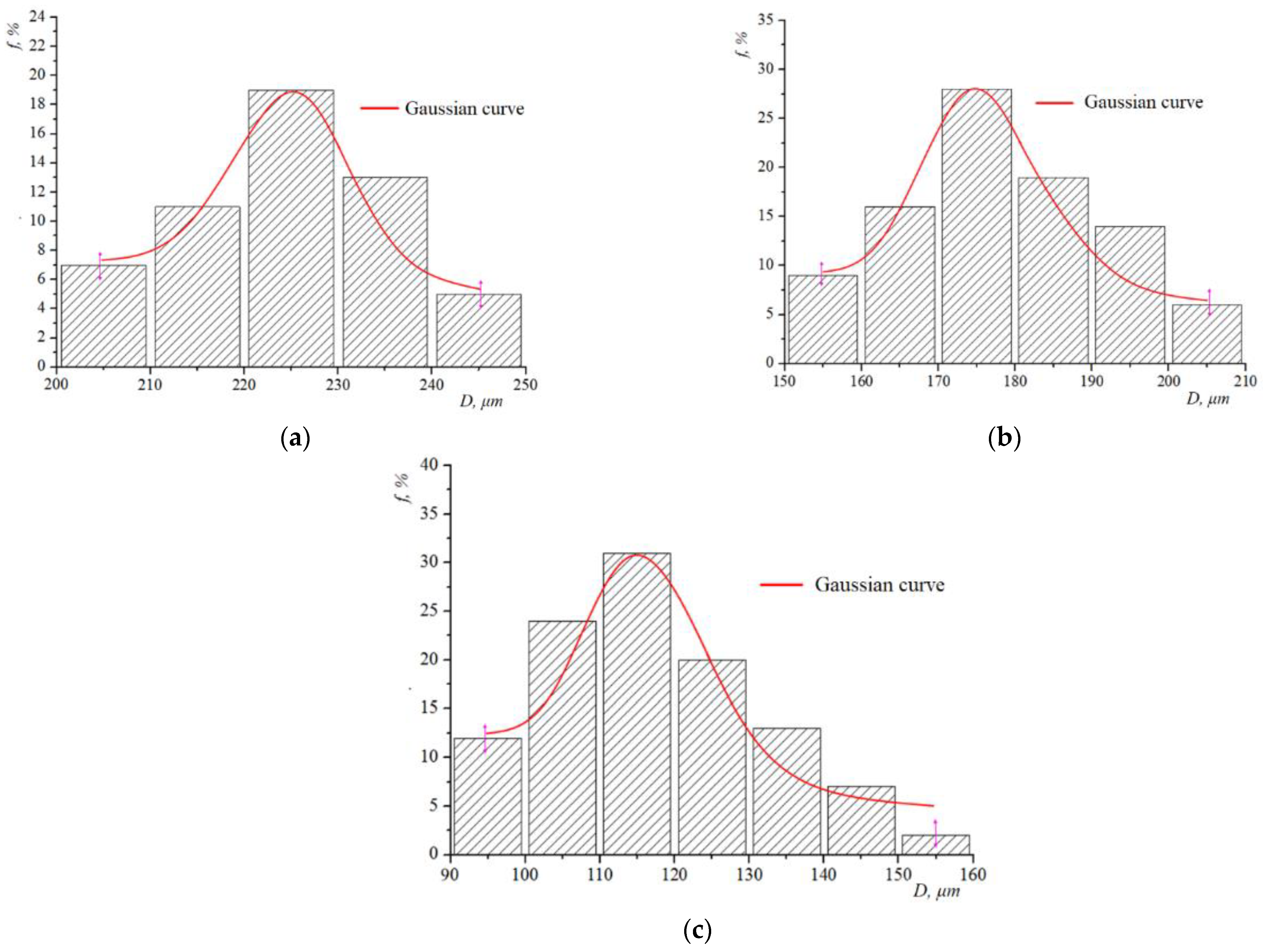
Figure 1. Illustrations to step 7: (a z i = h max + R i Δ ; (b) recalculation of h m a x  and Δ of the active layer.
Computation 11 00022 g001
Figure 2. Illustrations to step 7: (a) z i >   h max + R i Δ ; ; (b) recalculation of the values h m a x and Δ of the active layer.
Computation 11 00022 g002
Figure 3. Morphology of polyhedral particles of VT20 alloy powder for different fractions: (a) 200–250 μm, (b) 160–200 μm, (c) 100–160 μm.
Computation 11 00022 g003
Figure 4. Gaussian curves for distributions of powder alloy VT20 particles corresponding to various fractions after hydrogenation-dehydrogenation: (a) 200–250 microns, (b) 160–200 μm, (c) 100–160 μm.
Computation 11 00022 g004
Figure 5. Arrangement of particles for Fraction 1.
Computation 11 00022 g005
Figure 6. Arrangement of particles for Fraction 2.
Computation 11 00022 g006
Figure 7. Arrangement of particles for Fraction 3.
Computation 11 00022 g007
Table 1. Experimental distribution of titanium alloy powder particle sizes with polyhedral shapes.
Powder FractionExperimentally Determined Particle Sizes by Ferret Diameter, μmNumber of Particles
Pcs.%
Fraction 1
(200–250 μm)
96.612.3
156.924.7
199.71227.9
214.51739.5
228.3511.6
241.3614.0
Fraction 2
(160–200 μm)
178.81419.2
183.479.6
187.61824.7
193.61419.2
200.12027.4
Fraction 3
(100–160 μm)
75.956.6
92.333.9
106.279.2
118.467.9
129.556.6
139.822.6
149.379.2
158.32026.3
166.82127.6
Table 2. Filling factors for polyhedral particles.
Powder FractionExperimental Filling Factor, %Calculated Filling
Factor, %
Error, %
Fraction 1
(200–250 μm)
62.0759.432.64
Fraction 2
(160–200 μm)
67.1862.214.97
Fraction 3
(100–160 μm)
73.5668.774.79
Disclaimer/Publisher’s Note: The statements, opinions and data contained in all publications are solely those of the individual author(s) and contributor(s) and not of MDPI and/or the editor(s). MDPI and/or the editor(s) disclaim responsibility for any injury to people or property resulting from any ideas, methods, instructions or products referred to in the content.

