Article

Research on Optimization and Verification of the Number of Stator Blades of kW Ammonia Working Medium Radial Flow Turbine in Ocean Thermal Energy Conversion

1
Institute of Marine Science and Technology, School of Mechanical Engineering, Shandong University, Qingdao 266237, China
2
Key Laboratory of “High Efficiency Clean Advanced Manufacturing” Ministry of Education, Shandong University, Jinan 250061, China
3
Southern Marine Science and Engineering Guangdong Laboratory, Zhanjiang 524000, China
*
Author to whom correspondence should be addressed.
J. Mar. Sci. Eng. 2021, 9(8), 901; https://doi.org/10.3390/jmse9080901
Submission received: 5 August 2021 / Revised: 18 August 2021 / Accepted: 19 August 2021 / Published: 20 August 2021
(This article belongs to the Special Issue Ocean Engineering and Oceanography for Carbon Neutralization)

Abstract

:
Ocean Thermal Energy Conversion (OTEC) is one of the emerging industries of ocean energy and an important link in carbon neutrality. Turbine is a key component of ocean thermal energy conversion, which has an important impact on the performance and energy conversion efficiency of the system. This paper fully considers the application characteristics of ocean thermal energy conversion and the state conversion characteristics of ammonia working fluid. Taking the 100 kW radial inflow turbine in the OTEC application system as an example, based on the design, the turbine is optimized for the key parameters of the turbine stator and the influence of different geometric parameters is analyzed. Subsequently, the optimization results are verified by CFD numerical simulation analysis under different conditions. The results show that the number of stator blades has an important influence on the performance of the turbine. Further optimization studies have shown that through optimization, when the number of stator blades is 33, the internal flow field performance is the best, and the working conditions of the inlet and outlet working fluids are in accordance with the design points without obvious shock wave and reverse flow phenomenon, the efficiency is 89.46%, 3.94% higher than the design value.

1. Introduction

In a modern society with rapid economic and social development, understanding how to establish a balance between energy and the environment is an old topic. The development and utilization of marine renewable energy is a potential solution to this problem [1,2,3,4,5]. On the issue of recent climate change, the attention of ocean energy has increased to a higher level [6,7,8,9]. Ocean thermal energy conversion [10] is a new type of renewable energy and an important link in carbon neutrality. For example, if coal is solidified solar energy, then ocean thermal energy conversion is liquefied solar energy. Ocean thermal energy conversion [11] (OTEC) refers to the use of surface warm seawater to heat certain low-boiling point working fluids and vaporize them to drive steam turbines to generate electricity; at the same time, deep-layer cold seawater is used to condense the exhausted steam after work into liquid, forming System circulation. The temperature of seawater below 800 m is constant at about 4 °C, thus, the resource distribution of ocean temperature difference energy mainly depends on the surface temperature of the seawater. The lower the latitude, the higher the surface seawater temperature, the more abundant ocean thermal energy is stored. Theoretically speaking, the temperature difference energy resources can be developed and utilized in sea areas with a water depth of more than 800 m and a temperature difference of more than 18 °C. Therefore, among all kinds of marine energy, its resource reserves are very large. Different from coal, it is a new energy technology that is developed and applied, environmentally friendly, pollution-free, and inexhaustible [12,13]. Rankine cycle [14,15] is the most basic cycle of ocean thermal energy conversion, and the national ocean cycle [16] is currently the most efficient. In the cycle, the turbine is used to convert the internal energy of the working fluid into rotating mechanical energy and finally into electrical energy, the performance of which plays a decisive role in the output power and energy conversion efficiency of the entire power generation system. In various forms of turbines, the radial inflow turbine has fewer components, and the overall structure is simple and compact. In the case of reasonable design, the efficiency is higher. It can be used under the conditions of small flow, low pressure and low temperature. Achieve higher turbine efficiency.
Although turbines specially used for ocean thermal energy conversion have been applied in many thermoelectric energy systems abroad, there are not too many related documents to introduce and elaborate, and there are very few aspects of ocean thermal energy conversion radial inflow turbine stator optimization. In the ORC turbine optimization, Li Xiao [17] took the stator efficiency as the optimization goal, controlled the four angle parameters of the stator profile as design variables, and performed the response surface for the stator profile of the radial inflow turbine with organic working fluid. After analysis and optimization, the stator efficiency increased by 2% after optimization. Yonghui Xie et al. [18] took the maximum stress minimum as the optimization goal, and selected four parameters: the middle thickness of the blade hub, the middle thickness of the blade inlet end, the absolute airflow angle (the angle with the radial direction), and the relative airflow angle of the blade outlet. The geometry channel has been optimized. Li Yan et al. [19] used NURBS curves to conduct aerodynamic optimization research on organic working fluid radial inflow turbines, and optimized the stator blade profile and the meridian flow channel of the blade wheel to make the flow channel change more uniform. Tan Xin [20] used a high-precision flow field simulation method for a centrifugal annular cascade turbine. Based on the optimization method, the optimized single-row stator total pressure loss coefficient was reduced by 18.85%, and the wheel circumference efficiency of the entire stage was increased by 4.18%. Wang Xing et al. [21] found that in the stator design process, reducing the thickness of the front and middle sections of the stator can effectively reduce the stator loss coefficient; the change of the profile of the middle section of the blade suction surface has a greater impact on the blade loss coefficient, and the pressure surface of the blade. The change of the middle profile has the least influence on the stator loss coefficient. Peng Song et al. [22] took the total efficiency of the turbine as the optimization goal. The two-dimensional stators were parameterized by Bezier splines with 8 control points, and the rotor channel was generated by Bezier splines with 5 parameters. The runoff turbine has been aerodynamically optimized. Ayad et al. [23] used the B-spline curve technique to describe the blade angle and thickness changes, and used 20 design points to optimize the geometric structure of the stator and rotor blades, and finally determined the best blade shape of the turbine. Although there are many studies on ocean thermal energy conversion, most of the turbines currently used are directly borrowed from traditional thermoelectric turbines. However, the application requirements for different ocean temperature differences will be different, and the turbines need to be specifically designed and optimized [24]. Based on the experimental platform of the First Institute of Oceanography of the Ministry of Natural Resources and considering the application characteristics of ocean thermal energy conversion and the state conversion characteristics of ammonia working fluid, this paper takes the 100 kW ammonia working fluid radial inflow turbine in the national ocean cycle as the research object, designs the aerodynamic part and completes the CFD aerodynamic performance simulation analysis. The optimization goal was determined according to the characteristics of the internal flow field of the turbine, and the influence of the number of stator in the standard operating conditions on the turbine performance was further discussed, the aerodynamic performance of the turbine was optimized, and the expansion efficiency of the radial turbine was further improved, which provides a technical guarantee for improving the efficiency of ocean thermal power generation.

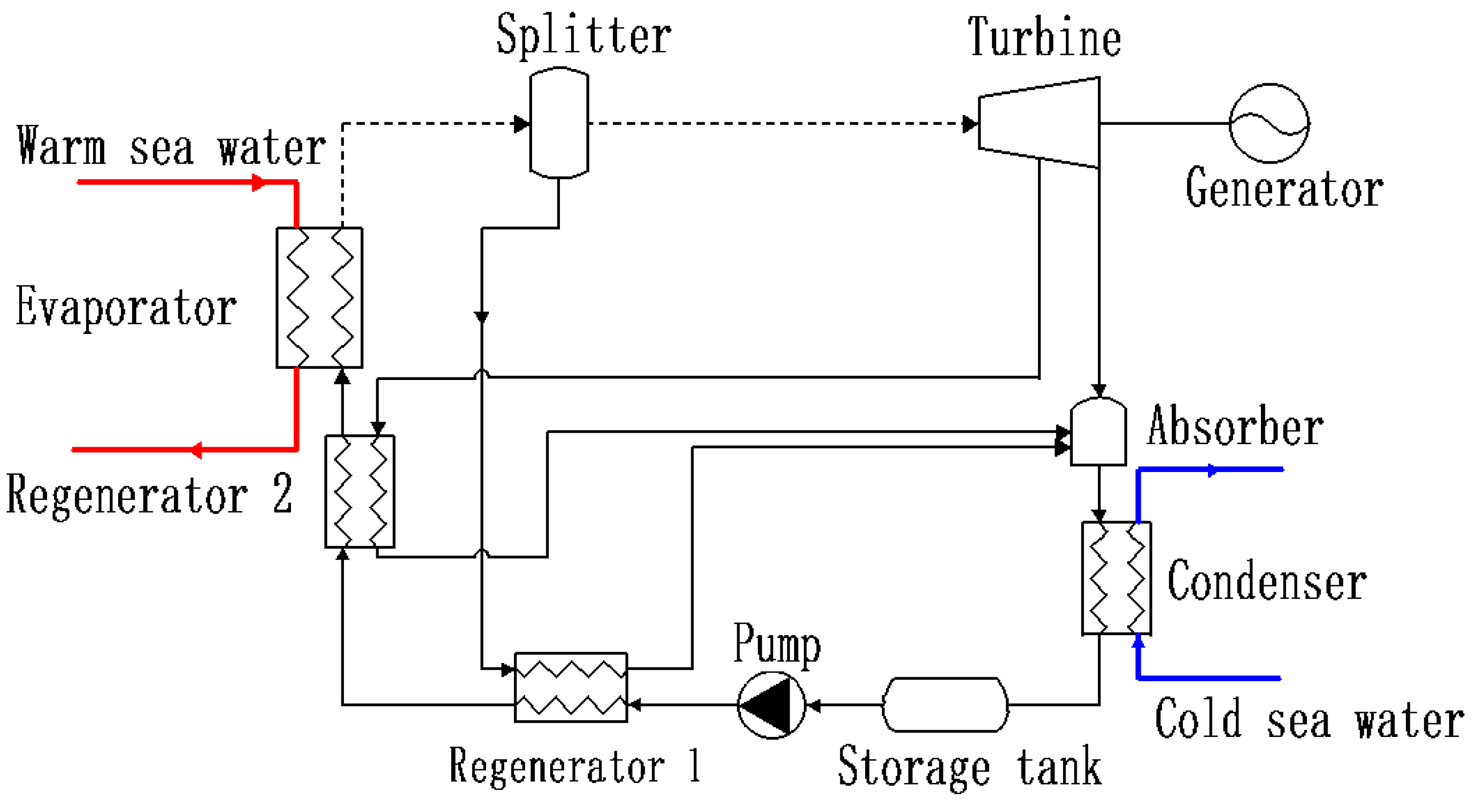
2. Materials and Methods

2.1. Turbine Aerodynamic Design and 3D Modeling

2.1.1. Selection of Pneumatic Parameters

The cycle system proposed by the First Institute of Oceanography, Ministry of Natural Resources [25], is shown in Figure 1. This cycle has the following characteristics: Firstly, the ammonia vaporized from the evaporator first passes through the separator, which ensures the purity of the gas passing through the turbine, and on the other hand, the lean ammonia solution from the separator passes through the regenerator 1, and preliminary heating of the solution from the pump to improve energy utilization. Second, part of the ammonia from the separator passes through the turbine to perform work, and the other part of the ammonia passes through the regenerator 2 to continue to heat the solution from the regenerator 1. The efficiency of the system is improved by fully applying the absorbed heat [16].
Based on the National Sea Cycle, the thermal calculation of the overall cycle system is first performed [26]. The relevant thermal parameters of the turbine inlet and outlet are obtained, and the results are shown in Table 1.

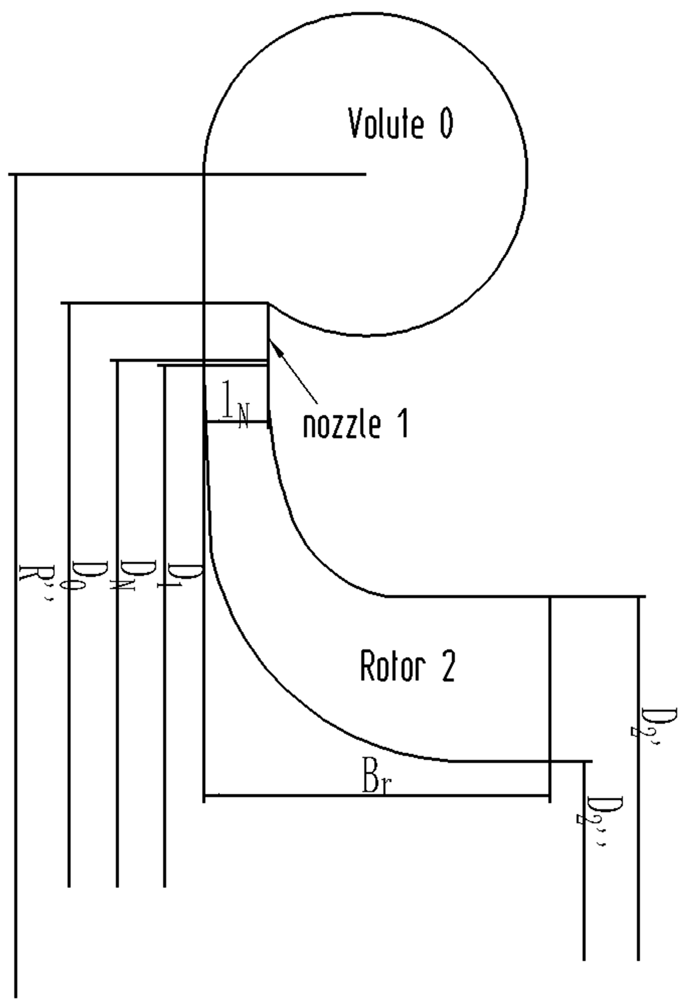
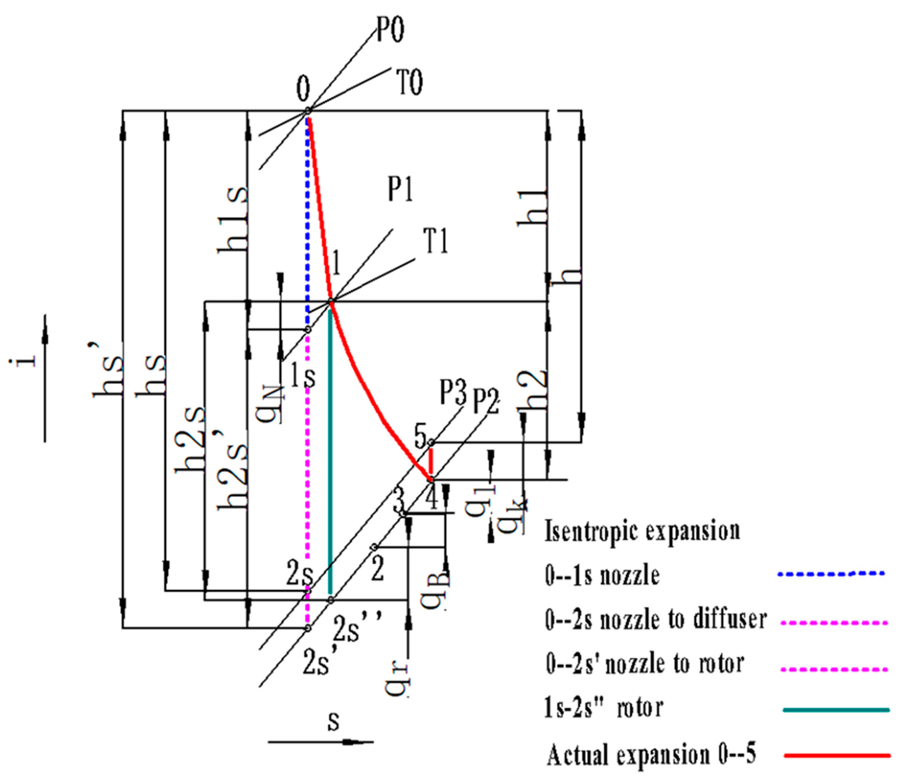
2.1.2. Initial Aerodynamic Design and Three-Dimensional Modling

Taking full account of the influence of the thermal properties of the ammonia working fluid and the environmental peculiarities (small temperature difference) in the actual application process of the ocean thermal energy conversion, combined with the design ideas of the ORC radial turbine [27,28], carry out the preliminary startup design and simulation of the turbine optimization. The overall working process and thermal conversion process of the ammonia working fluid radial inflow turbine are similar to the working process and thermal process of the R134 thermal energy conversion radial steam turbine previously designed by our team [29], as shown in Figure 2 and Figure 3. Since the focus of this article is to introduce the optimization of the ammonia working fluid radial inflow turbine nozzle, the one-dimensional aerodynamic design process will not be expanded in detail.
The ammonia working fluid first enters the volute, and the airflow flows evenly to the stator through the volute; the gas enters the stator for initial expansion, realizing the conversion of internal energy of gas to kinetic energy (0–1). The gas accelerated in the stator enters the rotor and the kinetic energy of the gas is transformed into the mechanical energy of the rotor, and finally converted into electrical energy. On the other hand, the gas expands further in the moving blades to complete the transformation from internal energy to mechanical energy (1–2), and the working fluid after work flows out after passing through the diffuser. Combining the working process of the turbine, based on the known design parameters, according to the unary flow theory, under the design conditions, by referring to the fluid properties of NISTREFPROP 9.0 [30], the thermal parameters of the ammonia working radial inflow turbine radially are calculated, and the main design dimensions and structure of the turbine are obtained, which mainly involve the volute, stator and rotor.
In the actual process of the preliminary design of radial inflow turbine with the ammonia working fluid, the selection of empirical parameters takes a lot of time. First, select the three dimensionless parameters reaction degree Ω, wheel diameter ratio μ, speed ratio u ¯ , and use genetic algorithm for single-objective optimization [31] to obtain the design value corresponding to the maximum turbine efficiency. If the three parameters obtained are within the parameter range given in the reference, the matching stator speed coefficient φ, rotor speed coefficient ψ, rotor inlet absolute airflow angle α1 and outlet relative airflow angle β2 are further determined; If it is not within the parameter range given in the reference, adjust the parameter to further optimize. Finally, the optimal 7 basic parameter values under the design conditions are obtained. The specific results and experience range [32] are shown in Table 2.
Specifically, the three dimensionless parameters reaction degree Ω, wheel diameter ratio μ, speed ratio u ¯ , are defined as follows:
Ω = h 2 s h s   ,
μ = D 2 D 1 = u 2 m u 1   ,
u ¯ 1 = u 1 C S ,
In addition, h 2 s and h s are the rotor isentropic enthalpy drop and permeability enthalpy drop, respectively, calculated by Equations (4) and (5), D 1 ,     D 2 ,   u 1 ,   u 2 m are the diameter and circumferential velocity of rotor inlet and outlet, C S is the ideal isentropic speed, calculated by Equation (6).
h 2 s = i 1 s i 2 s   ,
h s = i 0 i 2 s   ,
C S = 2 h s ,
The results of the initial aerodynamic design are shown in Table 3. It can be seen that the designed turbine output is 121.45 kW and the isentropic efficiency is 0.8552, which meets the requirements of the turbine design.
Based on the one-dimensional calculation, the corresponding three-dimensional modeling and meshing of the pneumatic components of the turbine are carried out. The volute is divided into tetrahedral meshes, whose tongue is locally encrypted. The rotor and stator are divided into hexahedral mesh, and the value of y+ near the wall of which is set to 30, and the O-shaped mesh is used to encrypt it. The overall grid assembled in the CFX pre-processing is shown in Figure 4, and the diffuser is not shown for the convenience of display.
In this article, the commercial numerical analysis software ANSYS CFX V19.0 [33,34] is used to verify the radial inflow turbine designed in the previous section. In the initial stage of the study, the total turbine inlet pressure was set to 0.83 MPa, the total temperature was 297.15 K, and the turbine outlet mass flow rate was 2.44 kg/s, which was calculated by cycles. The rotation speed of the rotor is 18,300 rpm. The relatively moving surface is set as Frozen-rotor, and the relatively static surface is defined as Stage-Frame Change, In addition, the “No Sliding Wall” option applies to all walls.

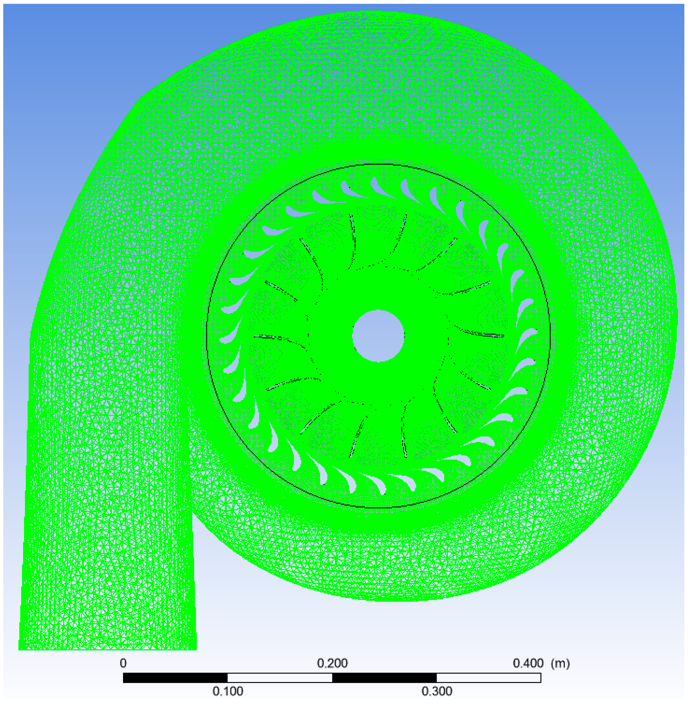
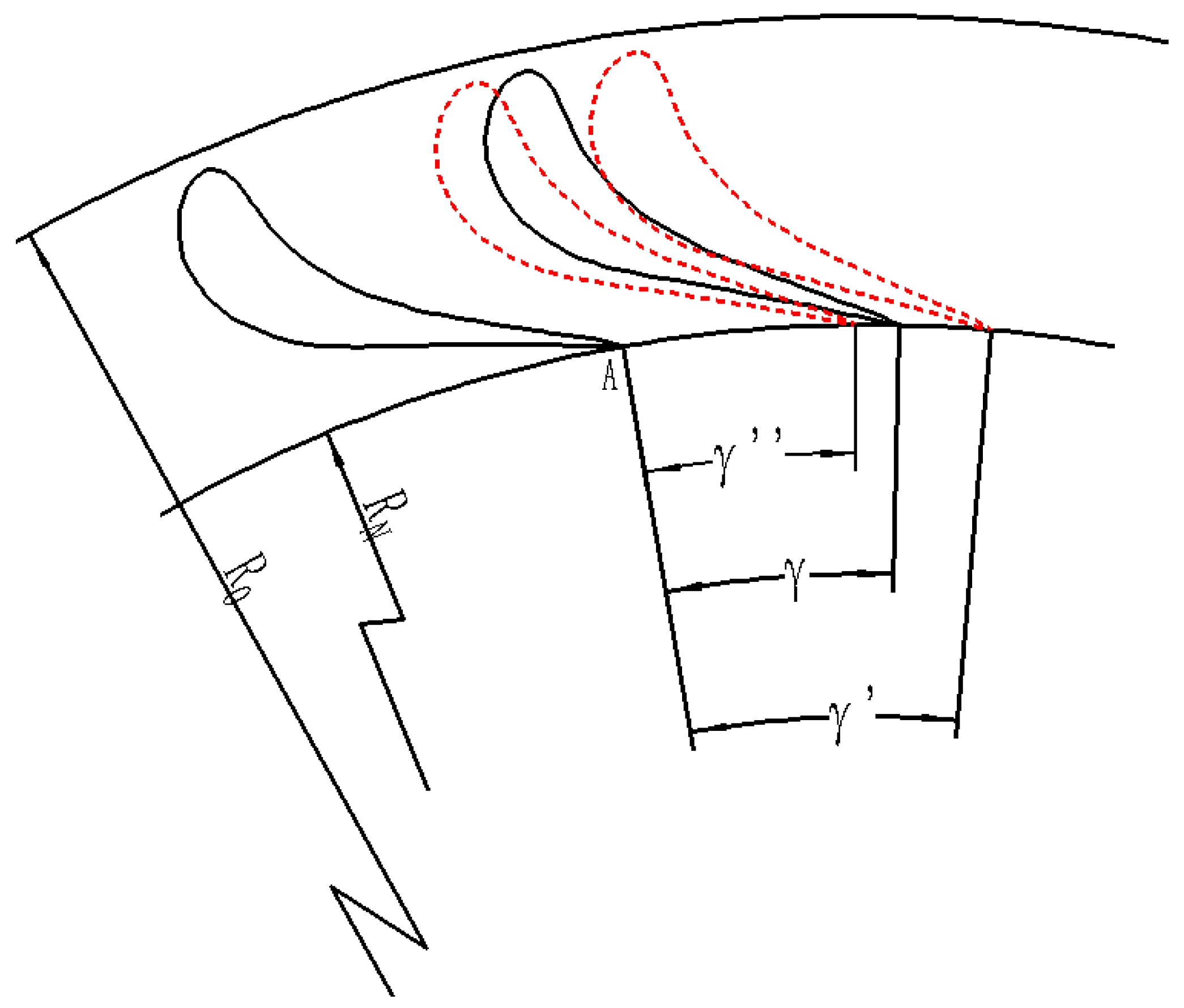
2.2. Optimized Method
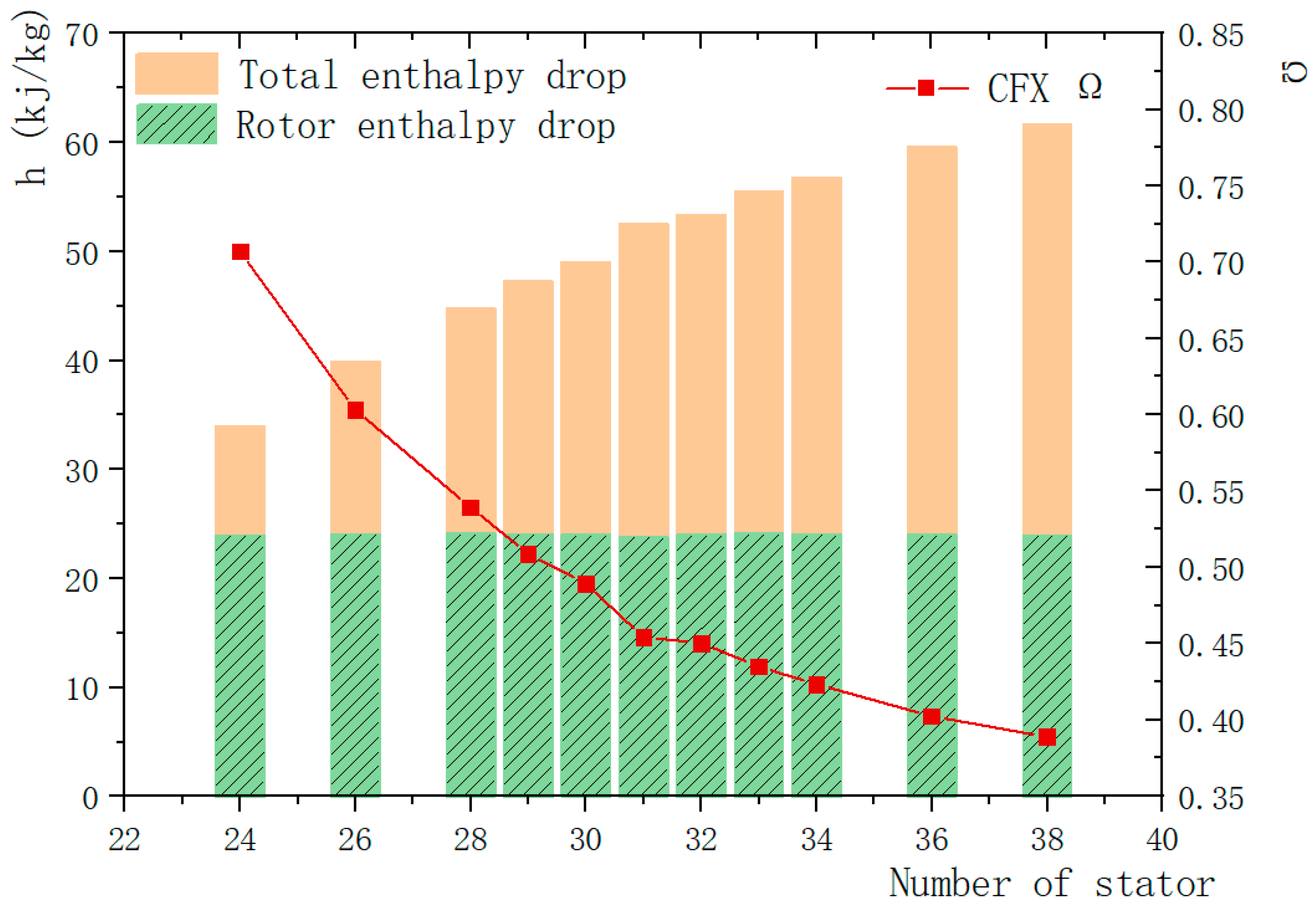
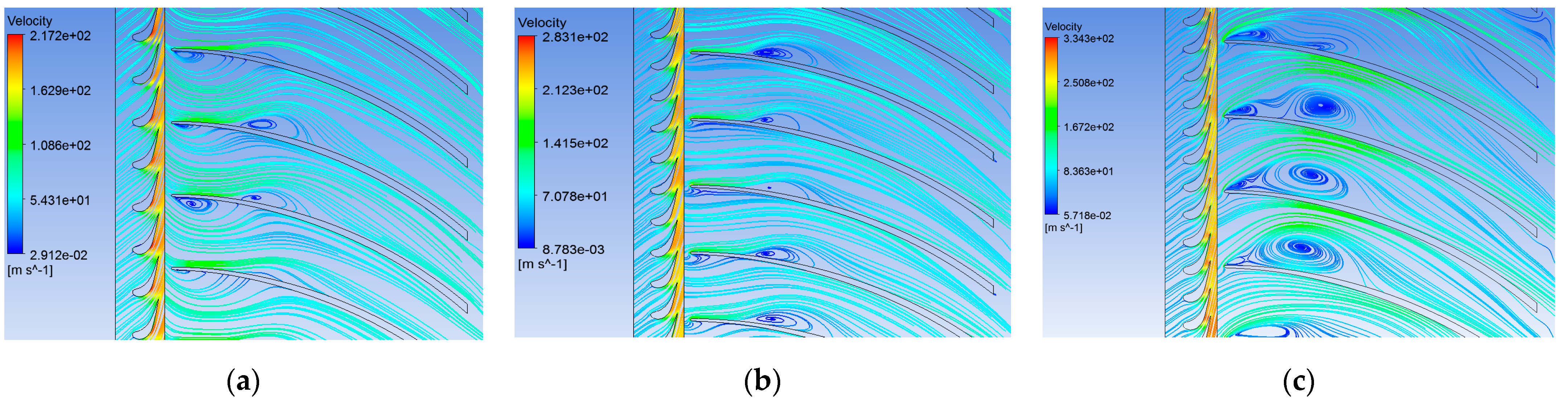
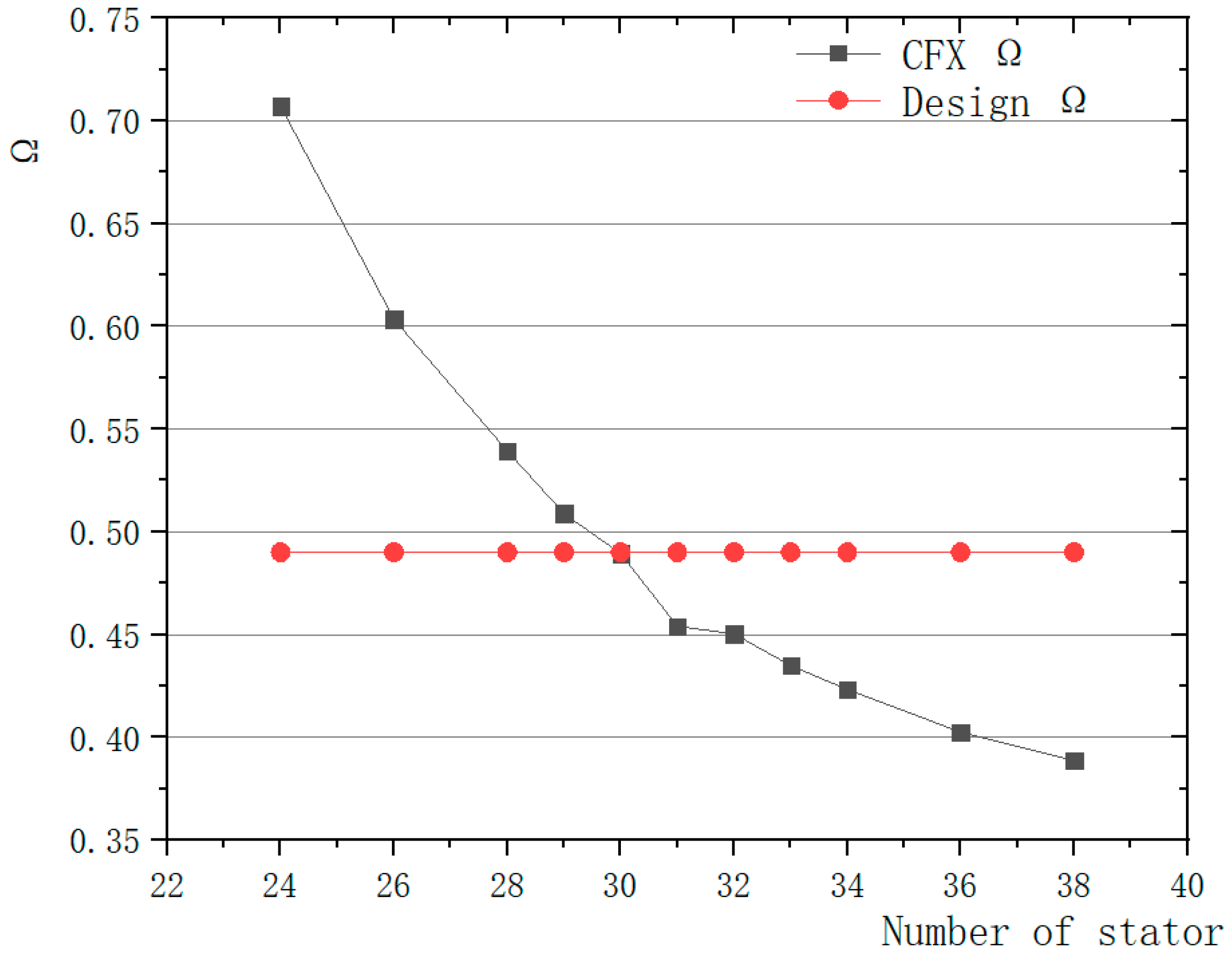
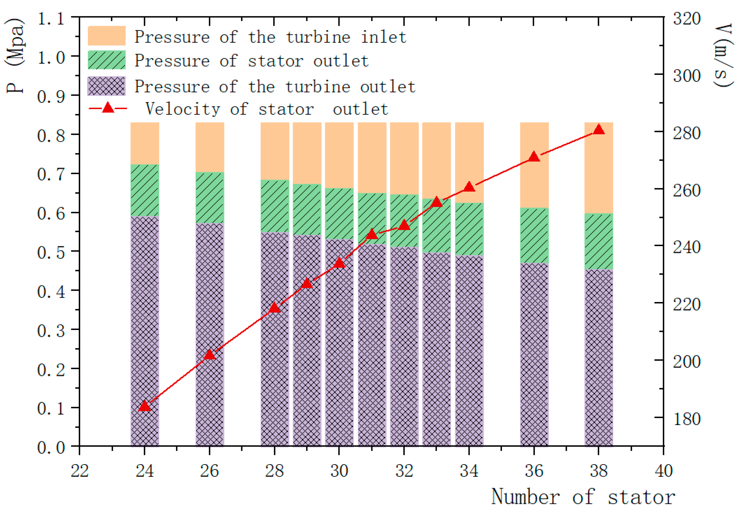
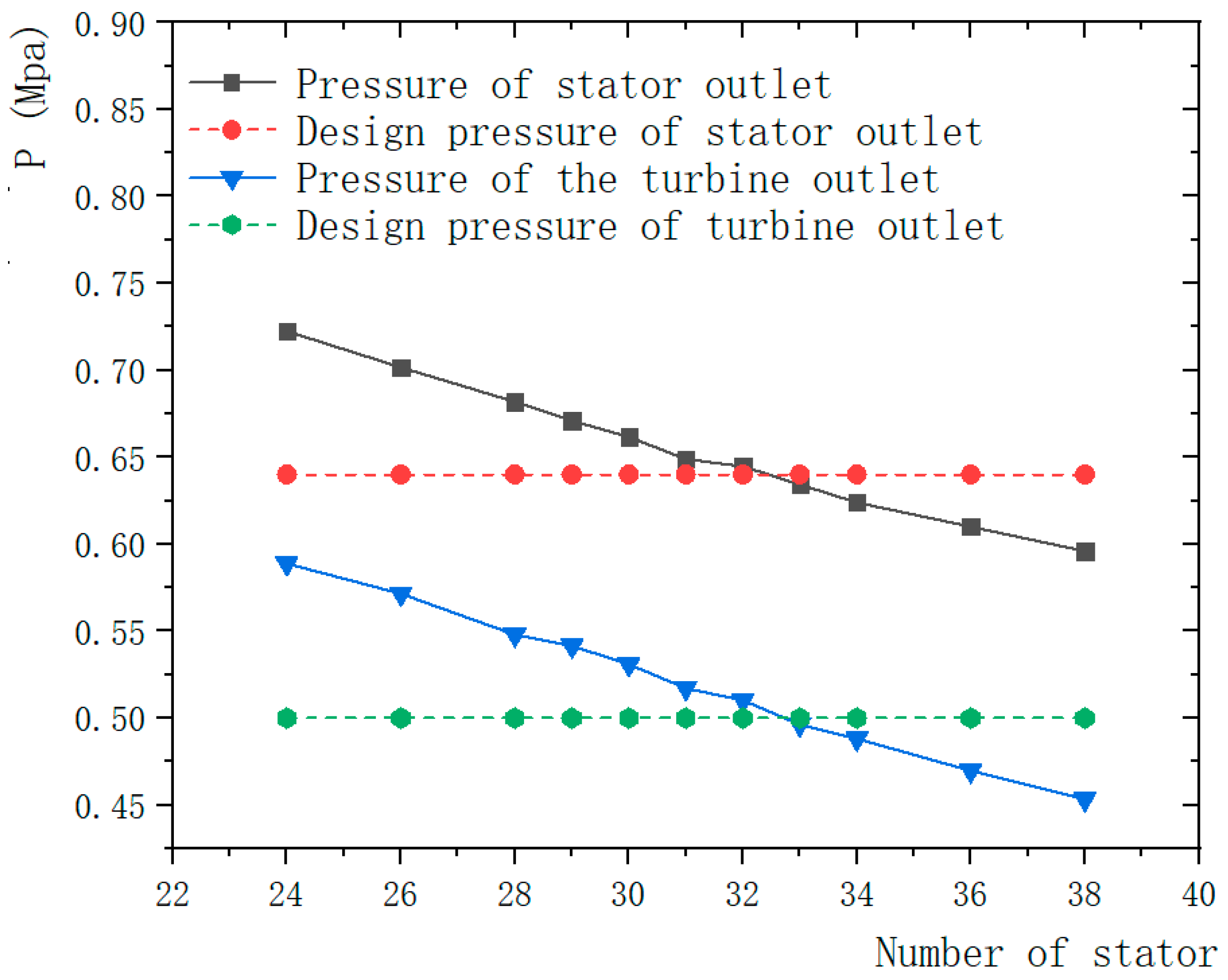
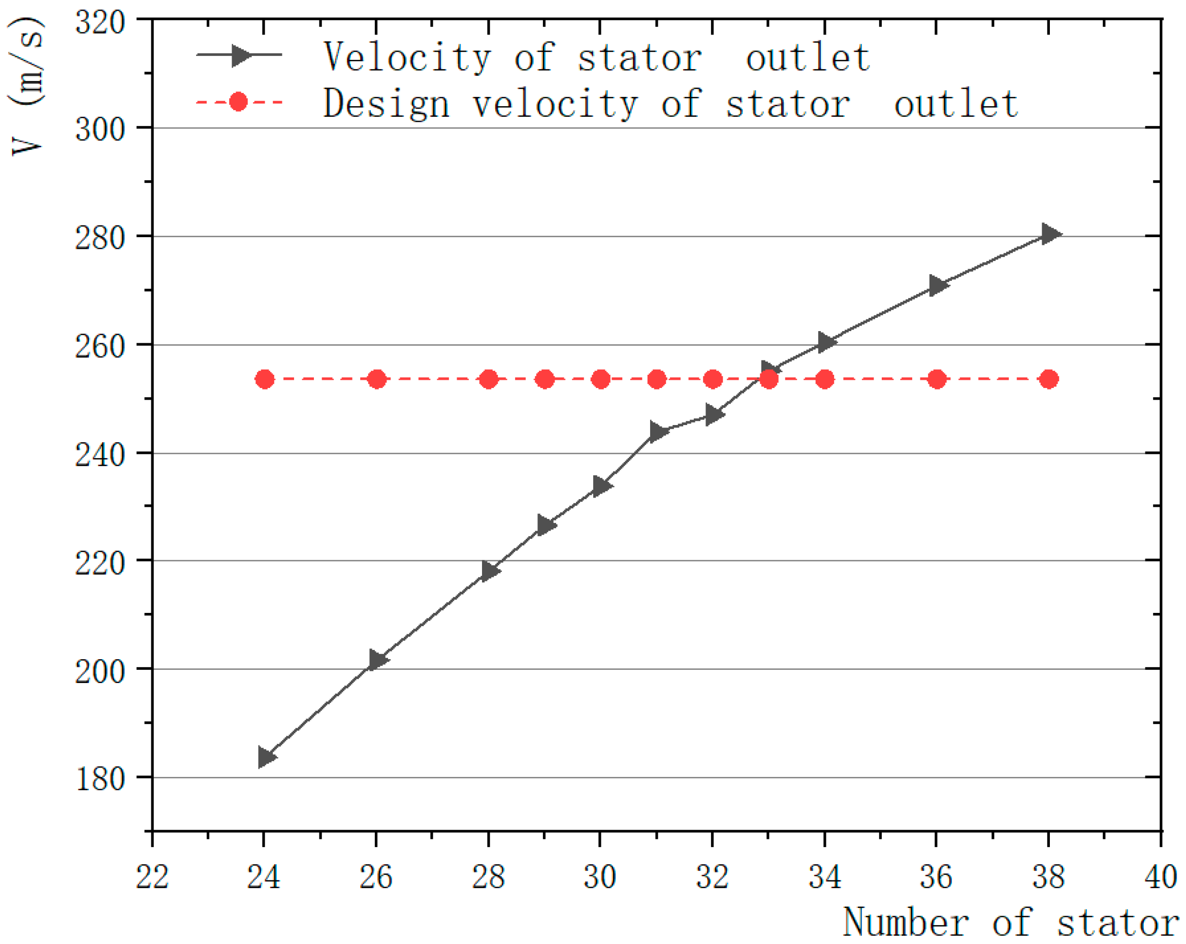
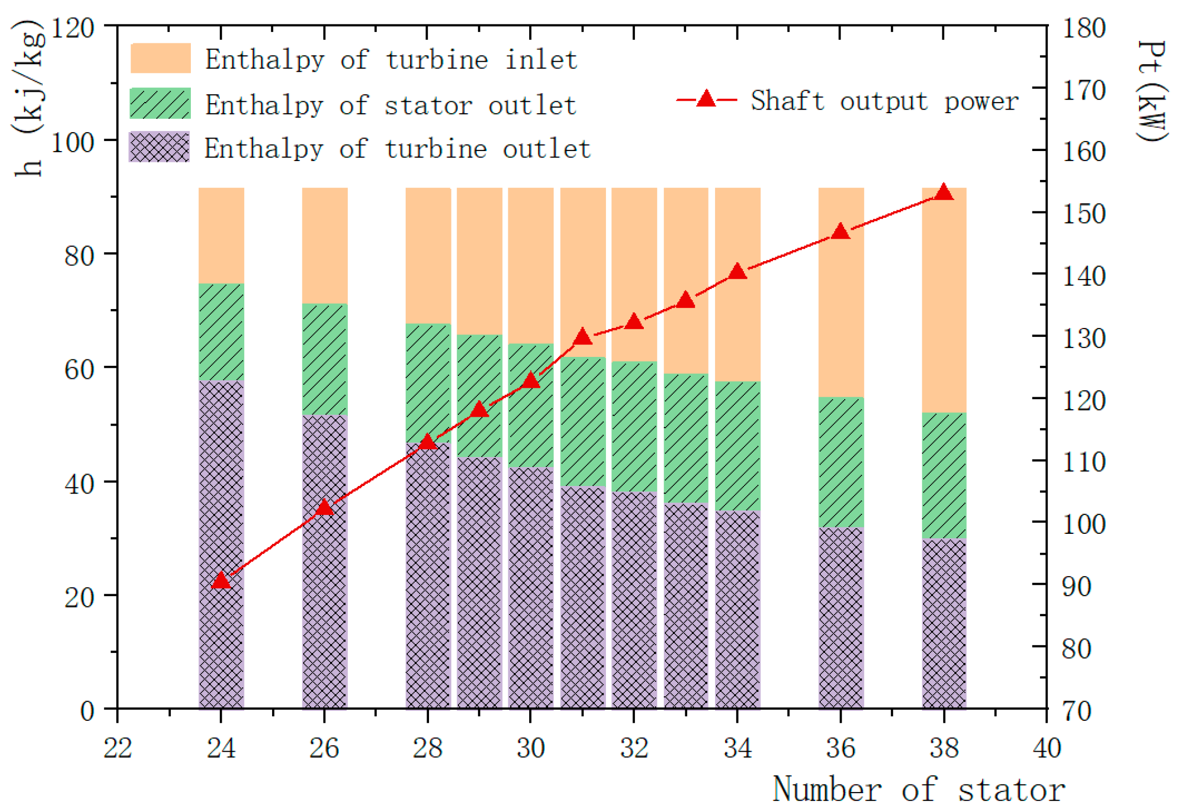
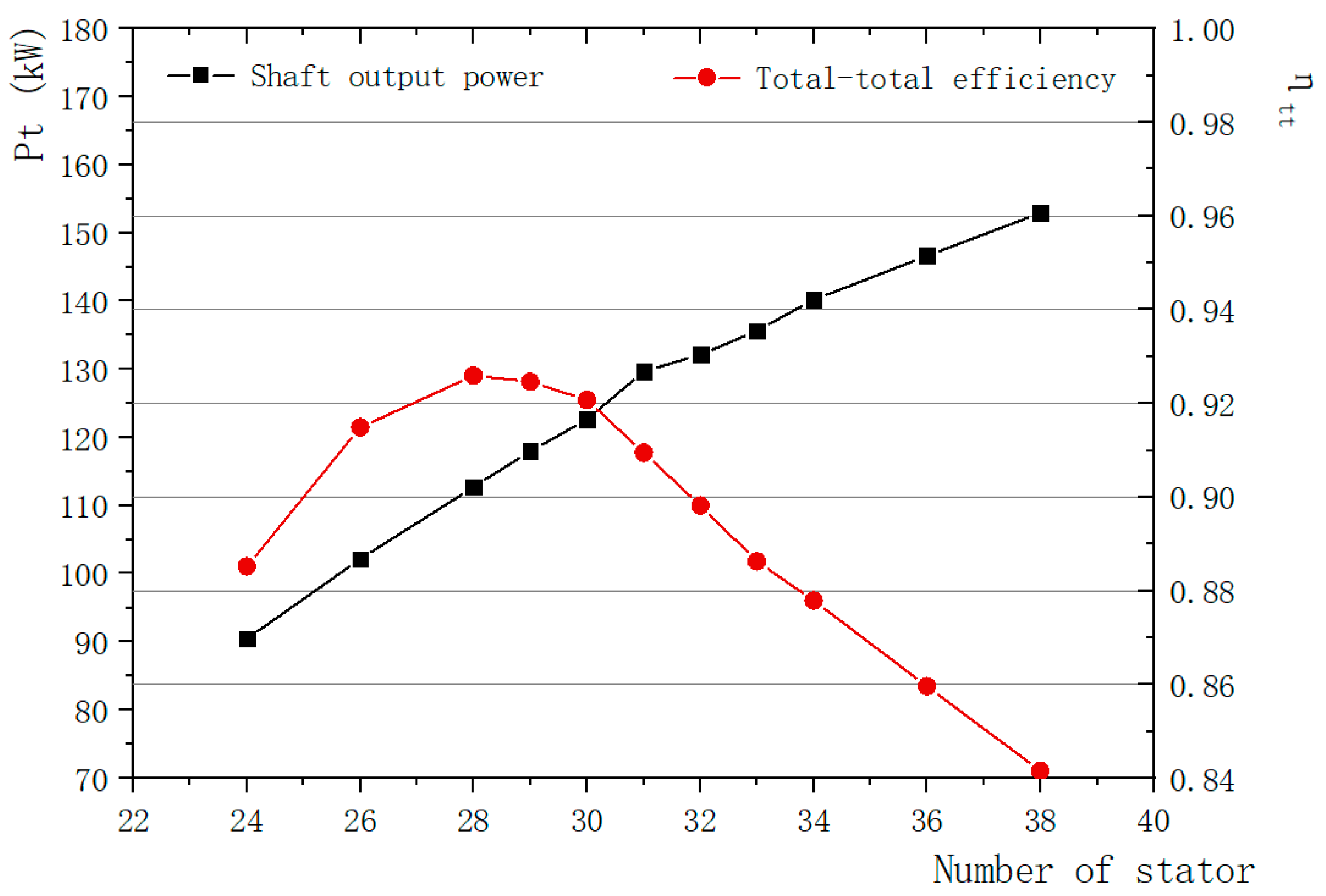
The number of stator blades is a key factor affecting the performance of the turbine. The gas from the volute enters the stator to make contact with the stator. A reasonable number of stator blades can not only achieve smooth flow distribution, but also enable the gas to complete ideal expansion in the stator. On the one hand, theoretically, the more stator blades, the smoother the streamlines and the more uniform streamlines entering the rotor. However, as the number of stator blades increases, the contact between the gas and the blade surface will increase, which will increase unnecessary Friction loss. At the same time, the increase in the number of blades will reduce the flow area, which is equivalent to increasing a part of the blocking loss. On the other hand, the number of stator blades will also affect the stator exit speed, and the stator exit speed is the absolute speed of the rotor inlet, which has an important influence on the speed and the airflow angle of the rotor inlet. If the matching is not good, a large flow loss will occur at the stator outlet and the rotor inlet, which will result in a decrease in the output work of the turbine and a decrease in the efficiency of the turbine.
On the premise that the stator-rotor radial gap remains unchanged, the optimization method is used to optimize the number of blades. By increasing and decreasing the number of stator blades around the design value, stator blades with different numbers of blades can be obtained. Firstly, the numerical simulation is carried out by selecting nearby points within the range of ±2 around the design point. After approaching the optimal number, the variation range is reduced to ±1, and the optimal solution is gradually approached. As shown in the figure, the number of stator blades has increased from 24 to 38, and the angle between stator blades has been reduced from γ’ to γ’’ and γ is the design point value, as shown in Figure 5.

3. Results

According to the above optimization method, 11 sets of design values are selected within the range of the number of stator blades from 24–38, which are respectively modeled and simulated in a full three-dimensional state. The influence of different blade numbers on the performance of the turbine is analyzed and the following results are obtained.
The effect of the number of stator blades on the total enthalpy drop of the turbine, the enthalpy drop of the rotor and the degree of reaction is shown in Figure 6. It can be seen from the figure that as the number of stator blades increases, the total enthalpy drop of the turbine increases, while the rotor enthalpy drop decreases, and the degree of reaction decreases as the number of stator blades increases. Along with the increase in the stator blades, the gas flow in the stator is more uniform and closer to idealization, so the total enthalpy drop of the turbine increases. However, the stator blades have a thickness, and the increase of the stator blades has a certain blocking effect. In the same situation, the speed of the stator outlet will increase, causing impact loss at the rotor inlet, so the rotor enthalpy drop decreases as the stator blades increase.
The degree of reaction is calculated by Equation (1), which reflects the relationship between the enthalpy drop of the rotor and the total enthalpy drop of the turbine, and which is a good predictor of the performance of the turbine. A large degree of reaction means that the expansion of the gas in the rotor accounts for a large proportion. Correspondingly, the expansion of the gas in the stator accounts for a small proportion. As a result, the stator outlet velocity is low, and the reverse flow is at the rotor inlet. The velocity streamline diagram when the number of stator blades is 24 in Figure 7a is shown, which shows that when the number of stator blades is small, gas can’t achieve good distribution and initial expansion. If the reaction is too small, it means that the expansion of the gas in the stator is greater than the expansion in the rotor, and the stator exit velocity is high, which will cause impact loss at the rotor entrance. In the velocity streamline diagram, there are streamline concentration on the pressure surface and vortex on the suction surface, as shown in Figure 7c (the number of stationary blades is 38). Both the reverse flow and the vortex on the suction side of the turbine will cause the flow loss of the turbine, which directly affects the output of the turbine and reduces the efficiency of the turbine. Therefore, it is particularly important to select the appropriate number of stator blades in the design.
The comparison between the design results and the simulation results of the degree of reaction corresponding to the number of stator blades is shown in Figure 8. When the number of stator blades is 30, the difference between the simulation result and the design result is the smallest. At this time, the corresponding streamline diagram is shown in Figure 7b. It can be seen from the figure that the gas is evenly distributed in the stator, especially from the stator outlet to the rotor inlet, the streamline has achieved a smooth transition, and the impeller reaches 90° air intake. There is no backflow, and there is no obvious suction surface vortex.
Figure 9 shows the effect of the number of stator blades on turbine inlet and outlet pressure, stator outlet pressure and stator outlet velocity. The boundary condition of the turbine inlet is the pressure inlet, so the inlet pressure is constant, and the boundary condition of turbine outlet is set as the mass flow outlet, so the outlet pressure is affected by the number of stator blades, and as the number of stator blades increases, the outlet pressure decreases. Therefore, the total pressure drop increases. The stator outlet pressure also decreases with the increase in the number of stator blades, which makes the pressure drop across the entire stator increase, so the speed of the stator outlet increases. The comparison curves of the calculated and simulated values of turbine inlet and outlet pressure, stator outlet pressure and stator outlet velocity are shown in Figure 10 and Figure 11. It can be seen from the figure that when the number of stator blades is 31 to 33, the turbine inlet and outlet pressure and the stator outlet pressure have the high degree of agreement between simulation value and the calculated value indicates that with this number of stator blades, the overall turbine expansion state is good, and the pressure drop gradient is uniform. When the number of stator blades is 33, the simulation result of the stator exit speed is the closest to the calculation result, indicating that the transition from the stator exit to the moving rotor entrance is more in line with the design value, so that it will not have a big impact on the moving rotor, nor will cause greater flow loss due to backflow.
Figure 12 shows the effect of the number of stator blades on the turbine inlet and outlet enthalpy, stator outlet enthalpy and shaft power. The boundary conditions of the turbine inlet are the same, so the inlet enthalpy is constant. However, as the number of stator blades changes, the flow state of the ammonia working fluid in the turbine will change. Correspondingly, the enthalpy of the turbine outlet and the enthalpy value of the stator outlet will be affected. It is obvious from the figure that the enthalpy value of the stator exit decreases as the number of stator blades increases, which increases the enthalpy drop of the entire stator, which directly leads to an increase in the speed of the stator exit. Moreover, as the number of stator blades increases, the enthalpy value of the turbine outlet also decreases, and the total enthalpy drop of the turbine increases, which is finally reflected in the change of shaft power. As shown by the curve in the figure, the shaft power keeps increasing as the number of stator blades increases. Shaft power can be calculated by Equation (7), which can better reflect the true value of shaft power in the simulation state:
Pt = n * t a     ,
Here, Pt is the shaft power/kW, t is the shaft torque/N·m, which can be obtained from the simulation results, a is a constant, and a = 9549.
Although the shaft power keeps increasing as the number of stator blades increases, the total-total efficiency is different. As shown in Figure 13, the total-total efficiency shows a trend of rising first and then falling with the increase in the number of stator blades. And before the number of stator blades is 30, the efficiency drops slowly. After the number of stator blades is 30, the efficiency drops rapidly. When the number of stator blades is 28, the maximum value of total-total efficiency is obtained. The total-total efficiency is defined as Equation (8):
η tt = h t t h s t t   ,
h t t = i i n i o u t   ,
h s t t = i s i n i s o u t ,
Among them, η tt is the total-total efficiency, h t t is the actual enthalpy drop, h s t t is the equal entropy enthalpy drop, i i n and i o u t are the total enthalpy of the turbine inlet and outlet respectively, and i s i n and i s o u t are respectively the total isentropic enthalpy of the turbine inlet and outlet. All above enthalpy values are all obtained by simulation.
Through the above analysis, it can be seen that when the number of stator blades is 33, the difference between the stator outlet speed, outlet static pressure and shaft power of the turbine is the smallest from the one-dimensional design result, and when the number of stator blades is 30, the reaction degree is closest to the originally given design value and the efficiency is the highest. The specific data are shown in Table 4. Both results are better than the results before optimization (the number of stator blades is 32).

4. Discussion

Through the above analysis, it can be seen that when the number of stator blades is 30 and 33, both have obvious advantages to a certain extent, and it is impossible to judge which result is the best through a standard. In order to further verify the analysis and ensure the scientificity of the results, the outlet boundary of the turbine was changed to static pressure 0.5 MPa, and other conditions were kept unchanged, and then the simulation was carried out, while paying attention to the outlet mass flow rate and turbine efficiency. The simulation data of the number of stator blades of 30 and 33 under the pressure inlet to pressure outlet conditions are obtained.
The comparison of simulation results is shown in Table 5. Under the boundary conditions of pressure inlet and pressure outlet, it can be seen from the comparison between the two sets of data in the table and the design value that when the number of stator blades is 33, the difference between the outlet mass flow and the design value is smaller. At the same time, comparing the two sets of data with the same number of stator blades under different import and export conditions, it can be seen that when the number of stator blades is 33, the two sets of data show better consistency, that is, when the inlet and outlet boundary conditions of the turbine are changed, the turbine can still show good working performance, and the robustness of the turbine is better.
After verification and analysis, combined with the optimization results of 3 sections, it can be concluded that under the design conditions, when the number of stator blades is 33, the performance of the turbine is the best.

5. Conclusions

In this paper, through the optimization of the number of stator blades of a radial inflow turbine with a 100 kW ammonia working fluid converted from ocean thermal energy, the following conclusions are obtained:
(1) Within a certain range, as the number of stator blades increases, the outlet pressure and outlet enthalpy of the turbine will decrease, and the shaft power will increase accordingly.
(2) Within a certain range, with the increase in the number of stator blades, the turbine stator outlet speed gradually increases. Outlet speed that is too slow will result in countercurrents and eddy currents at the inlet of the moving rotor, but an excessively large stator outlet speed will also have an impact on the moving rotor and increase the loss. Therefore, the total-total efficiency shows a trend of rising first and then falling with the increase in the number of stator blades.
(3) After optimization analysis and verification comparison, there is an optimal number of stator blades under design conditions to make the pressure field and velocity field the best, and at the same time obtain higher output power, efficiency and robustness. The optimal number of stator blades is 33. At this time, the efficiency is 89.46%, which is 3.94% higher than the design value, and the output power is 135.74kW, which meets the design requirements.
(4) The optimization research method in this study is simple and direct, and is suitable for the optimization of other parameters of the turbine. The results and verification analysis also have a certain reference effect and provide a certain method basis for future research.
(5) This study uses full three-dimensional simulation, and the simulation results are more accurate and reliable. However, due to the large number of grids, the corresponding simulation time is relatively long. In further research, the sampling method can be further optimized to improve the optimization speed

Author Contributions

Conceptualization, software, methodology, data curation, writing—original draft preparation and validation, Y.C.; conceptualization, supervision and funding acquisition Y.L. and Y.W. (Yongpeng Wu); supervision, Y.L.; writing—review and editing, W.Y. and Y.W. (Yiming Wang); project administration, L.Z. All authors contributed to the design of the study. All authors discussed, read, edited and approved the article. All authors have read and agreed to the published version of the manuscript.

Funding

This research was funded by the Fund of Southern Marine Scienceand Engineering Guangdong Laboratory (Zhanjiang) Project (ZJW-2019-05).

Institutional Review Board Statement

Not applicable.

Informed Consent Statement

Not applicable.

Acknowledgments

Thank you for the equipment support of the Ocean Thermal Energy Laboratory of the First Institute of Oceanography, Ministry of Natural Resources. Thanks to Yunzheng Ge, teacher of the First Institute of Oceanography, Ministry of Natural Resources.

Conflicts of Interest

The authors declare no conflict of interest.

References

  1. Carroquino, J.; Dufo-López, R.; Bernal-Agustín, J.L. Sizing of off-grid renewable energy for drip irrigation in Mediterranean crops. J. Renew. Energy 2015, 76, 566–574. [Google Scholar] [CrossRef]
  2. Crowley, B. Statistical review of world energy. Hydrocarb. Process. 2000, 79, 23. [Google Scholar]
  3. Zhang, X.P. Marine Energy: The Key for the Development of Sustainable Energy Supply. Proc. IEEE 2011, 100, 3–5. [Google Scholar] [CrossRef]
  4. Wang, S.; Yuan, P.; Li, D. An overview of ocean renewable energy in China. J. Renew. Sustain. Energy Rev. 2011, 15, 91–111. [Google Scholar] [CrossRef]
  5. Bahaj, A.S. Generating electricity from the oceans. J. Renew. Sustain. Energy Rev. 2011, 15, 3399–3416. [Google Scholar] [CrossRef]
  6. Martínez, M.L.; Vázquez, G.; Pérez-Maqueo, O.; Silva, R.; Moreno-Casasola, P.; Mendoza-González, G.; López-Portillo, J.; MacGregor-Fors, I.; Heckel, G.; Hernández-Santana, J.R.; et al. A systemic view of potential environmental impacts of ocean energy production. J. Renew. Sustain. Energy Rev. 2021, 149, 111332. [Google Scholar] [CrossRef]
  7. Feng, C.; Ye, G.; Jiang, Q.; Zheng, Y.; Chen, G.; Wu, J.; Feng, X.; Si, Y.; Zeng, J.; Li, P.; et al. The contribution of ocean-based solutions to carbon reduction in China. J. Sci. Total Environ. 2021, 797, 149168. [Google Scholar] [CrossRef]
  8. Zereshkian, S.; Mansour, Y.D. A study on the feasibility of using solar radiation energy and ocean thermal energy conversion to supply electricity for offshore oil and gas fields in the Caspian Sea. J. Renew. Energy 2021, 163, 66–77. [Google Scholar] [CrossRef]
  9. Hernández-Fontes, J.V.; Martínez, M.L.; Wojtarowski, A.; González-Mendoza, J.L.; Landgrave, R.; Silva, R. Is ocean energy an alternative in developing regions? A case study in Michoacan, Mexico. J. Clean. Prod. 2020, 266, 121984. [Google Scholar] [CrossRef]
  10. Avery, W.H.; Wu, C. An energy alternative. (Book reviews: renewable energy from the ocean. A guide to OTEC.). J. Sci. 1994, 265, 419–420. [Google Scholar]
  11. Vega, L.A. Ocean thermal energy conversion primer. J. Mar. Technol. Soc. J. 2002, 36, 25–35. [Google Scholar] [CrossRef]
  12. Zhang, X.; Li, X.; Shi, Y.; Wang, Y. The development status and prospect of ocean energy. J. Sci. Technol. Vis. 2015, 16, 258. [Google Scholar]
  13. Yage, Y.; Wei, L.; Weimin, L.; Xiaoying, L.; Feng, W. Development status and prospects of ocean energy power generation technology. J. Autom. Electr. Power Syst. 2010, 34, 1–12. [Google Scholar]
  14. Al-Weshahi, M.A. Working fluid selection of low grade heat geothermal Organic Rankine Cycle (ORC). Int. J. Therm. Sci. 2014, 4, 6–12. [Google Scholar]
  15. Imran, M.; Park, B.S.; Kim, H.J.; Lee, D.H.; Usman, M.; Heo, M. Thermo-economic optimization of regenerative organic rankine cycle for waste heat recovery applications. Energy Convers. Manag. 2014, 87, 107–118. [Google Scholar] [CrossRef]
  16. Chen, F.; Liu, L.; Peng, J.; Ge, Y.; Wu, H.; Liu, W. Theoretical and experimental research on the thermal performance of ocean thermal energy conversion system using the rankine cycle mode. Energy 2019, 183, 497–503. [Google Scholar] [CrossRef]
  17. Li, X.; Li, Z.; Zhang, Y. Study on the optimization of the organic working fluid centripetal permeable calm leaf shape. Therm. Turbine 2017, 46, 258–262. [Google Scholar]
  18. Xie, Y.; Deng, Q.; Zhang, D.; Feng, Z. Strength design and numerical analysis of radial inflow turbine rotor for a 100kW microturbine. Turbo Expo Power Land Sea Air 2005, 46997, 881–888. [Google Scholar]
  19. Li, Y.; Gu, C. Research on aerodynamic optimization of a centripetal turbine with a high expansion ratio organic working fluid. J. Eng. Thermophys. 2013, 34, 1239–1242. [Google Scholar]
  20. Tan, X.; Guo, H.J.; Li, H.; Huang, D.G. Centrifugal turbine blade design based on NURBS curve. J. Therm. Energy Power Eng. 2017, 32, 47–53. [Google Scholar]
  21. Wang, X.; Liu, X. Response surface analysis and optimization of organic working fluid turboexpander stator. J. Xi’an Jiaotong Univ. 2015, 49, 7–13. [Google Scholar]
  22. Song, P.; Sun, J.; Wang, K.; He, Z. Development of an optimization design method for turbomachinery by incorporating the cooperative coevolution genetic algorithm and adaptive approximate model. In Proceedings of the ASME 2011 Turbo Expo: Turbine Technical Conference and Exposition, Vancouver, BC, Canada, 6–10 June 2011. [Google Scholar]
  23. Al Jubori, A.M.; Al-Dadah, R.; Mahmoud, S. Performance enhancement of a small-scale organic Rankine cycle radial-inflow turbine through multi-objective optimization algorithm. Energy 2017, 131, 297–311. [Google Scholar] [CrossRef]
  24. Liu, W.; Ge, Y.; Liu, L.; Chen, Y. Current Development and Prospect of Turbine in OTEC. 2020. Available online: https://library.oapen.org/bitstream/handle/20.500.12657/43849/external_content.pdf?sequence=1#page=65 (accessed on 19 August 2021).
  25. Liu, W.M.; Chen, F.Y.; Wang, Y.Q.; Jiang, W.J.; Zhang, J.G. Progress of Closed-Cycle OTEC and c of OTEC. J. Adv. Mater. Res. 2012, 354, 275–278. [Google Scholar] [CrossRef]
  26. Chen, F.; Zhang, L.; Liu, W.; Liu, L.; Peng, J. Thermodynamic Analysis of Rankine Cycle in Ocean Thermal Energy Conversion. Int. J. Simul. Syst. 2016, 17, 7.1–7.4. [Google Scholar]
  27. Li, Y.; Lu, G. Radial Inflow Turbine and Centrifugal Compressor, 1st ed.; Machinery Industry Press: Beijing, China, 1992; pp. 110–132. [Google Scholar]
  28. Xu, Z.W.; Guo, H.Y.; Zheng, Z.J.; Jiang, X.H.; Zheng, Y. Improvement of Design Technology for a Radial Inflow Turbine Guide Vane and Its Application. Tuijin Jishu J. Propuls. Technol. 2017, 38, 2358–2364. [Google Scholar]
  29. Chen, Y.; Liu, Y.; Zhang, L.; Yang, X. Three-dimensional performance analysis of a radial–inflow turbine for ocean thermal energy conversion system. J. Mar. Sci. Eng. 2021, 9, 287. [Google Scholar] [CrossRef]
  30. Higashi, Y. NIST thermodynamic and transport properties of refrigerants and refrigerant mixtures (REFPROP). J. Netsu Bussei 2000, 14, 1575–1577. [Google Scholar]
  31. Zhang, J.H.; Zhou, Z.G. Aerodynamic Optimization Design of Radial Turbine Based on Parallel Genetic Algorithm. Aeroengine 2015, 41, 39–43. [Google Scholar]
  32. Bekiloglu, H.E.; Bedir, H.; Anlas, G. Multi-objective optimization of ORC parameters and selection of working fluid using preliminary radial inflow turbine design. J. Energy Convers. Manag. 2019, 183, 833–847. [Google Scholar] [CrossRef]
  33. Rocha, P.C.; Rocha, H.B.; Carneiro, F.M.; da Silva, M.V.; Bueno, A.V. k–ω SST (shear stress transport) turbulence model calibration: A case study on a small scale horizontal axis wind turbine. Energy 2014, 65, 412–418. [Google Scholar] [CrossRef]
  34. Louda, P.; Sváček, P.; Fořt, J.; Fürst, J.; Halama, J.; Kozel, K. Numerical simulation of turbine cascade flow with blade-fluid heat exchange. Appl. Math. Comput. 2013, 219, 7206–7214. [Google Scholar] [CrossRef]
Figure 1. National Sea Cycle.
Jmse 09 00901 g001
Figure 2. Schematic of the radial inflow turbine meridional view.
Jmse 09 00901 g002
Figure 3. Turbine thermodynamic process enthalpy and entropy change diagram.
Jmse 09 00901 g003
Figure 4. Turbine overall grid diagram.
Jmse 09 00901 g004
Figure 5. Changes in the number of stator blades.
Jmse 09 00901 g005
Figure 6. The influence of the number of stator blades on the total enthalpy drop of the turbine, the enthalpy drop of the rotor and the reaction degree.
Jmse 09 00901 g006
Figure 7. Velocity streamline diagram of 50% leaf height under different number of stator blades. (a) The number of stator blades is 24; (b) the number of stator blades is 30; (c) the number of stator blades is 38.
Jmse 09 00901 g007
Figure 8. Comparison of design value and simulation value of reaction degree at different number of stator blades.
Jmse 09 00901 g008
Figure 9. The influence of the number of stator blades on the pressure of the turbine inlet and outlet, the pressure of stator outlet and the velocity of stator outlet.
Jmse 09 00901 g009
Figure 10. Comparison of design value and simulation value of turbine inlet and outlet pressure and stator outlet pressure at different number of stator blades.
Jmse 09 00901 g010
Figure 11. Comparison of design value and simulation value of stator outlet velocity under different at different number of stator blades.
Jmse 09 00901 g011
Figure 12. The influence of the number of stator blades on the enthalpy of the turbine inlet and outlet, the enthalpy of the stator outlet and the shaft power.
Jmse 09 00901 g012
Figure 13. The influence of the number of stator blades on turbine shaft power and total-total efficiency.
Jmse 09 00901 g013
Table 1. Thermal parameters of the turbine inlet and outlet given by cycle calculation.
Thermal ParametersResults
Inlet total pressure p1/MPa0.83
Inlet total temperature T1/K297.15
Outlet static pressure p3/MPa0.5
Massflow rate m ˙ / kg·s−12.44
Isentropic efficiency ηs/-0.85
Table 2. The basic parameters and result.
Empirical ParametersDesign ValueExperience Value
Ω0.490.35–0.55
μ0.440.3–0.5
u ¯ 10.6230.65–0.7
φ0.950.95–0.97
ψ0.860.75–0.85
α116.3112–30
β233.5920–45
Table 3. Initial aerodynamic design results.
Basic ParameterDesign Value
Rotor speed N/r·min−118,300
Power output P/kW121.45
Isentropic expansion efficiency ηs/-0.8552
Height of stator inlet lN/mm9.38
Diameter of stator inlet D 0 / mm326
Diameter of stator onlet D N / mm242
Rotor inlet absolute airflow angle α116.31
Rotor inlet relative airflow angle β190.29
Rotor inlet circumferential speed u1/m·s−1244.11
Rotor inlet absolute speed c1/m·s−1253.57
Rotor inlet relative speed w1/m·s−169.89
Rotor inlet diameter D1/mm240
Rotor inlet height l1/mm11
Rotor outlet absolute airflow angle α287.46
Rotor outlet circumferential speed u2/m·s−1100.53
Rotor outlet absolute speed c2/m·s−174.87
Rotor outlet relative speed w2/m·s-1129.60
Rotor outlet absolute airflow angle β233.59
Rotor outlet outer diameter D2′/mm128
Rotor outlet inner diameter D2″/mm62
Rotor outlet height l 2 / mm32
Rotor axial length Br / mm72
Diffuser inlet diameter D k / mm128
Diffuser outlet diameter D 3 / mm200
Diffuser length L / mm342
Table 4. Statistics and comparison of simulation data for the optimal number of stator blades.
ParametersDesign Result3033No Optimization (32)
Stator outlet velocity c1/m·s−1253.57233.83232.90247.06
Outlet static pressure p3/MPa0.500.530.500.51
Reaction degree Ω0.490.490.430.45
Total-total efficiency ηtt/%85.5292.0788.6389.82
Shaft power Pt/kW131.45122.65135.66132.11
Table 5. Comparative analysis of verification results.
Boundary ConditionsOne-DimensionalDesign ResultP to M 1P to P 2
Number of Stator Blades30333033
Stator outlet velocity c1/m·s−1253.57233.83232.90251.72253.88
Outlet static pressure of p3/MPa0.50.530.500.50.5
Mass flow m ˙ /kg·s−12.442.442.442.572.44
Reaction degree Ω0.490.490.430.43350.4282
Total-total efficiency ηtt/%85.5292.0788.6390.1589.46
Shaft power Pt/kW131.45122.65135.66143.31135.74
1 Pressure inlet to mass flow outlet. 2 Pressure inlet to pressure outlet.
Publisher’s Note: MDPI stays neutral with regard to jurisdictional claims in published maps and institutional affiliations.

