Article

Mitigation Effect of Perforation Drilling on the Sliding Risk during Spudcan Installation Close to Footprints

College of Ocean Science and Engineering, Shanghai Maritime University, Shanghai 201306, China
*
Author to whom correspondence should be addressed.
J. Mar. Sci. Eng. 2020, 8(2), 118; https://doi.org/10.3390/jmse8020118
Submission received: 13 January 2020 / Revised: 12 February 2020 / Accepted: 13 February 2020 / Published: 14 February 2020

Abstract

:
Perforation drilling is a promising technique to mitigate the sliding risk of jack-up units installed around footprints. Based on the coupled Eulerian–Lagrangian (CEL) method, a 1/2 finite element model, including a rigid Lagrangian spudcan and a Eulerian soil part, was established, and the contact interface was modelled with the Coulomb friction model. Validated against an indoor perforation test, the model was adopted to investigate the mitigation mechanism and effects of the borehole diameter, number, depth, and the drilling range. The simulations reveal that the mitigation efficiency increases with the borehole diameter, number, and depth. However, it shows little improvement if the borehole depth increases beyond double footprint depth. The semi-drilling at the outer side of the footprint is a little more effective than the full-drilling at both the inner and outer sides of the footprint. The present work emphasizes the effects of perforation drilling parameters on the mitigation efficiency, which are of great significance to guide the engineering practice and guarantee the safe operation of the jack-up reinstallation close to existing footprints.

1. Introduction

The jack-up unit is widely used in offshore drilling and exploration due to its significant mobility and economic efficiency. After development of offshore oil and gas fields in the past few decades, a large number of depressions have been left on the seabed after the extraction of spudcans, which are often referred to as “footprints” [1]. When the jack-up unit has to be installed in the vicinity of a footprint, the spudcan may slide towards the footprint, as adverse horizontal forces and bending moments on the spudcan would be induced due to the asymmetric ground underneath. Excessive sliding could lead to poor positioning of the jack-up unit, or even cause the whole platform to capsize. Therefore, study of the sliding risk during spudcan re-installation close to footprints and its mitigation measures are of great significance to the operational safety of jack-up units.
It is only in the last two decades that much attention has been paid to the re-installation of jack-up units near existing footprints. Stewart and Finnie [1] initiated the study of spudcan–footprint interaction and investigated the effect of the offset distance between the spudcan and the footprint. Cassidy et al. [2] and Gan [3] assessed the influence of an existing footprint on the bearing capacity and potential horizontal displacement of the spudcan using a geotechnical centrifuge. Gan et al. [4] studied the effect of remolded soil consolidation on the spudcan–footprint interaction. Subsequently, Gaudin et al. [5] stated that the force on the spudcan in the vicinity of the existing footprint depended on the geometry and soil properties of the footprint, as well as the structural characteristics of legs and jack-up units. Kong et al. [6,7] further studied the effect of footprint’s geometry on the reinstallation of a jack-up and investigated the failure mechanisms. More recently, Fang et al. [8] studied the re-penetration of a spudcan on sand. Yuan et al. [9] conducted a 1g test of the re-installation of a three-legged jack-up unit. Besides experimental studies, further insights were recently provided by some numerical studies conducted by Mao et al. [10], Zhang [11], and Yu et al. [12]. Furthermore, Zheng et al. [13] numerically studied the spudcan–footprint interaction in non-uniform clay. Jun et al. [14] used the numerical simulation method to study the global behavior of a jack-up unit close to a footprint.
Mitigation measures to alleviate the sliding risk during the spudcan installation close to footprints can be divided into two categories, namely, footing modifications and seabed modifications [15]. For the first category, Hossian et al. [16] laid a foundation by experimental studies of the effect of spudcan’s shape on spudcan–footprint interaction. Jun et al. [17,18,19] proposed some novel spudcan shapes for easing spudcan–footprint interaction and optimized the shapes through experimental and numerical investigations. For the other category, the “perforation drilling” technique was proposed as a measure of seabed reconstruction, by weakening the bearing capacity of the soil outside the footprint which reduces the eccentricity of the soil under the spudcan. Hossain et al. [20] and Hossain and Stainforth [21] conducted preliminary tests on the “perforation drilling” through experiments and verified the effectiveness of the method in mitigating the sliding risk. Although it has not been successfully implemented in engineering practice to reduce sliding risk, its feasibility to mitigate the punch-through risk in layered clays has been verified in the field [22,23]. Besides, Hartono et al. [24] verified the effectiveness of reaming, however it was very time consuming.
Although the above relevant researches have gained much understanding of the spudcan–footprint interaction, the study on the mitigation effect of perforation drilling is still very limited. In this paper, the coupled Eulerian–Lagrangian method implemented in ABAQUS software was adopted to establish a reasonable numerical model, and the model is validated against a centrifugal test. Then, the effect of “perforation drilling” on the sliding risk mitigation is studied. Finally, further study of the effects of perforation drilling parameters, such as the borehole diameter, number, depth, and the drilling range, are conducted. They are believed to be of great significance for future engineering practices.

2. CEL Model and Verification

Figure 1 shows the schematic diagram of the spudcan penetration close to a footprint which is perforated, and also indicates two drilling range configurations adopted in the present study. Based on previous researches on footprint geometry, the footprint dimensions are selected as 2D wide and 0.33D deep for clay deposit. Additionally, the footprint has a conical shape with a slope angle θ of 18.5°, which represents the upper bound of the profiles recorded in previous tests (Hossain and Stainforth [21]). The perforation boreholes are drilled around the footprint with a depth of hhole. The spudcan is positioned with an offset β from the footprint center.

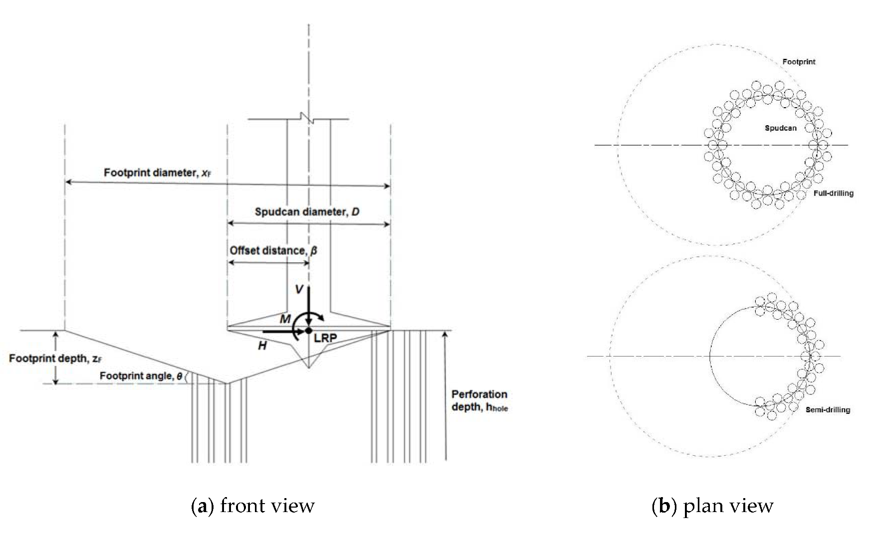
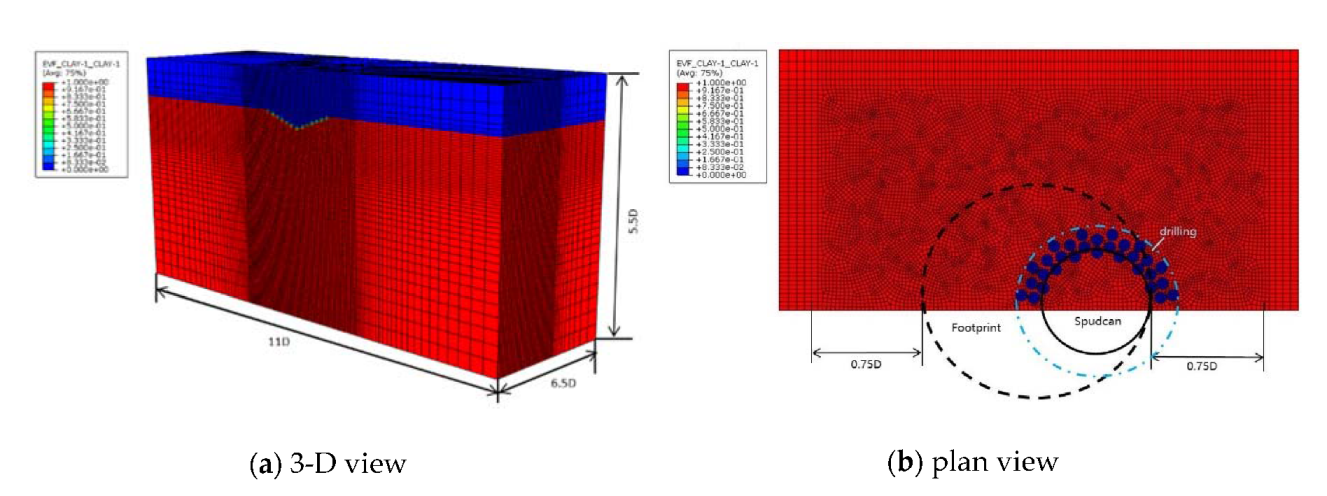
2.1. Finite Element Model

Qiu et al. [25], Tho et al. [26], and Wang et al. [27] all verified that the CEL method can effectively solve the problem of mesh distortion and numerical dispersion in large deformation problems. In this paper, the finite element model is established with the CEL method implemented in Abaqus. In the CEL model, the element volume fraction (EVF) represents how much the element is filled with material. As shown in Figure 2, the EVF_CLAY = 1 means that the element is fully filled with clay.
As the elastic deformation of the spudcan and leg is neglectable, they are set as rigid bodies and discretized with the three dimensional eight nodes elements with reduced integration, denoted as C3D8R. Due to the symmetry of the problem, a 1/2 model was established to reduce the computational cost. As shown in Figure 2, the soil in the numerical model is 11D long, 6.5D wide, and 5.5D deep. It is discretized with the three dimensional eight nodes Eulerian elements with reduced integration, denoted as EC3D8R. As the soil around the spudcan and footprint encounters severe deformation during spudcan penetration, the local mesh is refined, as shown in Figure 2b. The average mesh size in the refined zone is bclay = 0.03D.

2.2. Boundary Conditions

All translational degrees of freedom are restrained at the bottom of the soil, and the symmetric boundary condition is applied to the side boundaries with the normal degree of freedom constrained. The normal direction of spudcan–soil contact is set as “hard contact”, with which no penetration between the contact surfaces are allowed. The Coulomb friction model is adopted to model the tangential behavior of the contact, and the friction coefficient μ between the spudcan and soil is set as 0.3. However, a shear stress limit τlimit at the contact interface is set as the undrained shear strength of the soil, which is the same as the work of Yu et al. [12]. This is to allow sliding between the soil and spudcan if the frictional shear stress exceeds the undrained shear strength of the soil.

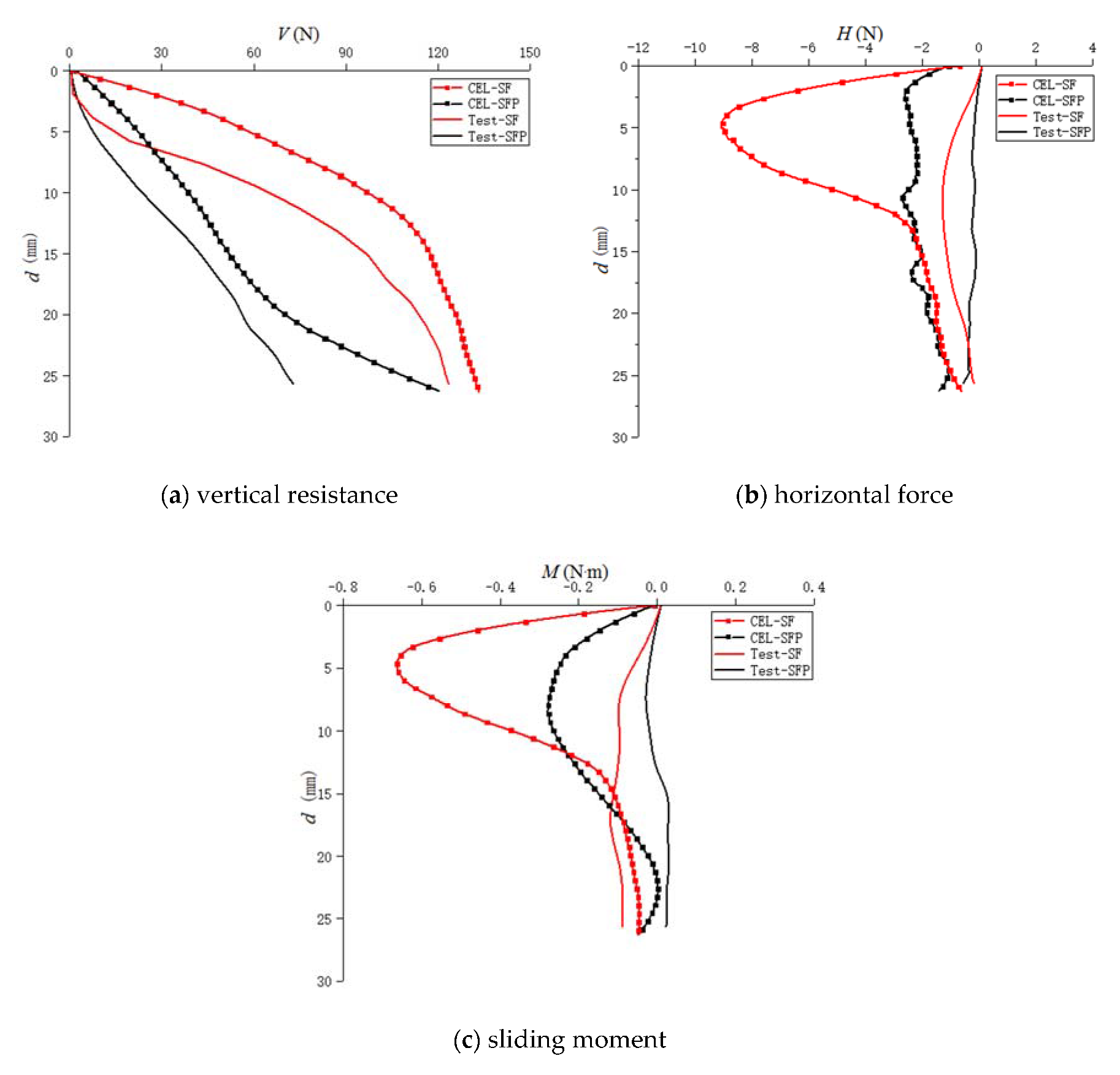
2.3. Model Validation

The numerical model is validated against the 1 g test carried out by Hossain and Stainforth [21]. In the test, the perforation drilling holes formed a pattern of four circles which are concentric to the spudcan, with the diameter ranging from 0.9D to 1.2D (see Figure 1). The holes’ diameter is dhole = 0.062D. The model established considers the normal consolidation of clay, and the clay is modeled as an ideal elastoplastic obeying the Tresca strength criterion. The clay parameters used in the model are listed in Table 1.
Simulation results of both the cases with and without perforation drilling were compared with the test results. As show in Figure 3, the vertical reaction force V, the horizontal sliding force H, and the bending moment M are plotted against the spudcan penetration depth d, which is defined as the depth of the load reference point (LRP, see Figure 1). It is worth noting that H and M first increase and then decrease as the depth increases, and their peak values do not occur at the bottom of the footprint, but at a shallower depth. It is also shown that H and M are significantly reduced by the perforation drilling, which is consistent with the conclusions of Hossain and Stainforth [21].
In the validation case, the numerical simulation exactly resembles the mitigation effect of perforation drilling in the test. However, the numerical result of the force and bending moment is generally larger than the test. This may be attributed to two reasons: one is that the undrained shear strength of the clay used in the simulation is linearized from testing, which introduces error; and the other is that the force and bending moment in the test was not obtained directly but by processing the measured strain on the leg, which might induce measurement error.

3. Results and Discussion

Although Hossain and Stainforth [21] proved the effectiveness of perforation drilling in easing spudcan–footprint interaction, effects of the borehole diameter, number, depth, and range on the mitigation efficacy are still unclear. To study their effects, five series of numerical simulations were conducted, with the parameters listed in Table 2. Series C1 is the base series which simulates the spudcan penetration close to a footprint without any perforation drilling. The other series were conducted to study the effects of perforation borehole parameters.
In the present work, numerical simulations are conducted with the same clay parameters listed in Table 1, and the same footprint profile as Hossain and Stainforth [21].

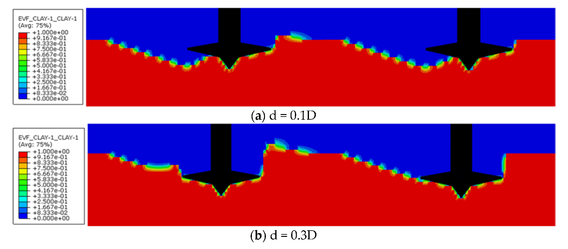
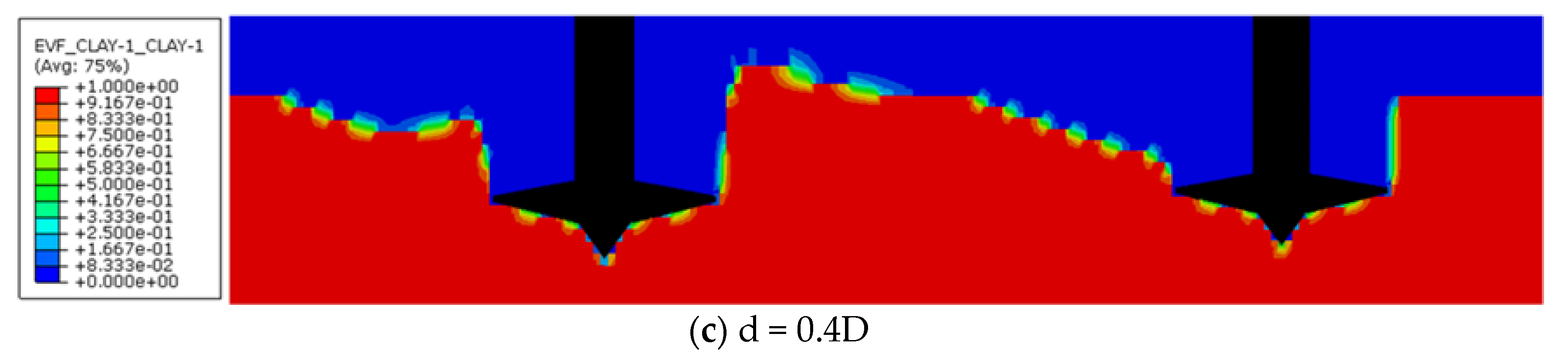
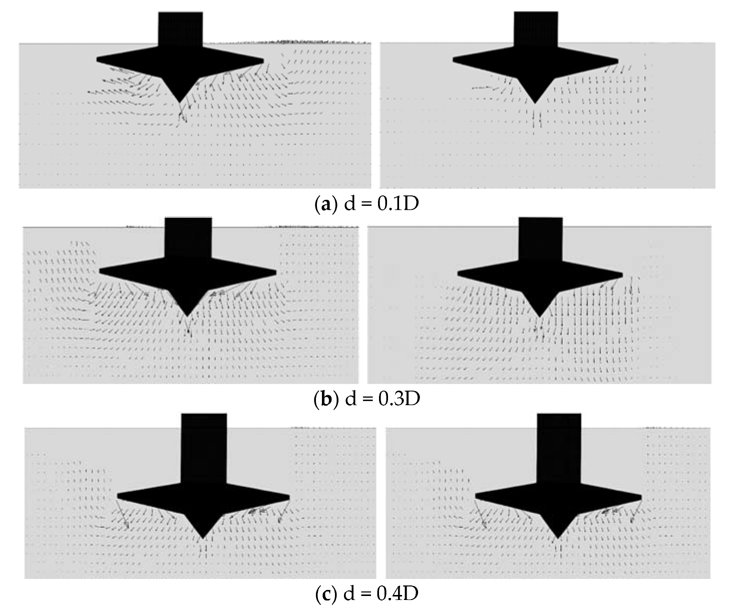
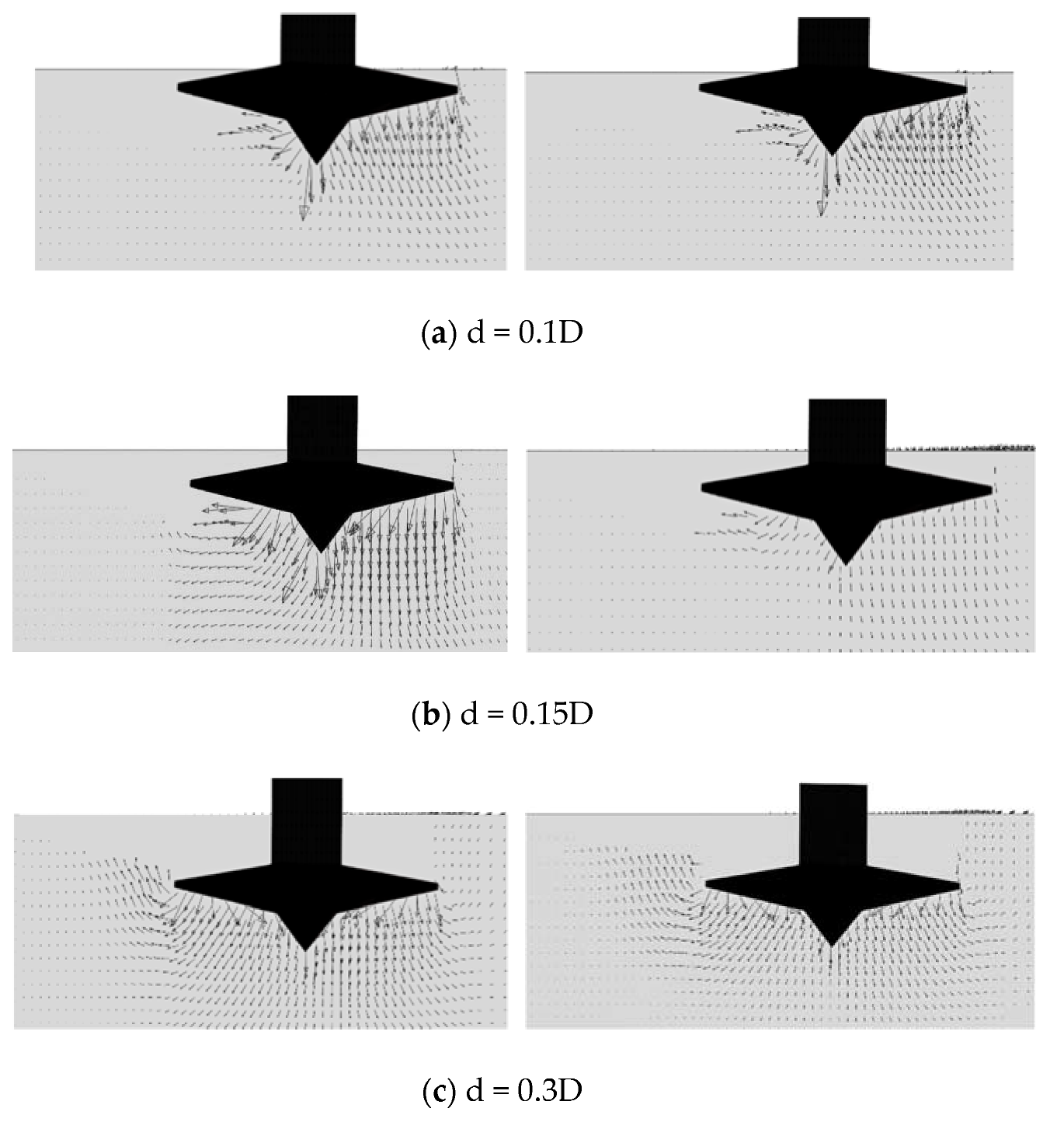
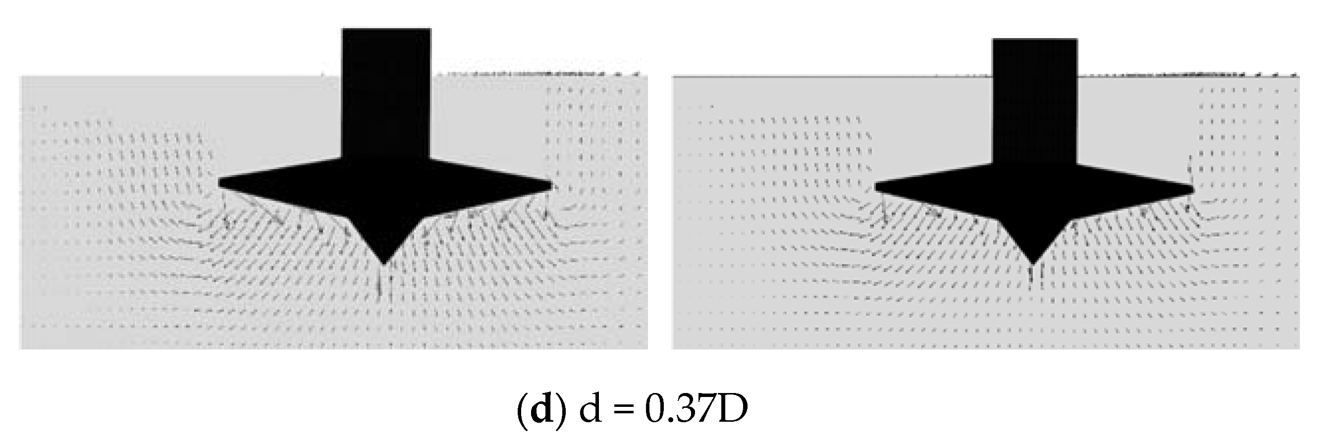
3.1. Mitigation Mechanism

The soil flow mechanism during the spudcan installation close to a footprint without and with drilling is analyzed. As shown in Figure 4, soil deformations at different penetration depths in C1-SF and C2-SFP are compared. The left side of the figure is the un-perforated condition, while the right side is the perforated condition. For the case without perforation, general shear failure occurs to the soil, and the soil at the soil surface rises, forming a heave. However, the soil is locally damaged in the case with perforation, and there is no significant soil heave at the soil surface. For the case with perforation, there is no significant soil heave at the soil surface and no obvious backflow around the spudcan in the whole penetration process.
Moreover, it is shown in Figure 5a that the distortion zone of the soil is significantly larger in the un-perforated case. The velocity vector has a significant component in the horizontal direction, while it is vertically downward with little horizontal component in the case with perforation. The less horizontal velocity component and soil distortion zone indicate less sliding force induced in the perforated case. In general, the perforation drilling method can effectively reduce the horizontal sliding force and mitigate the sliding risk of spudcans.

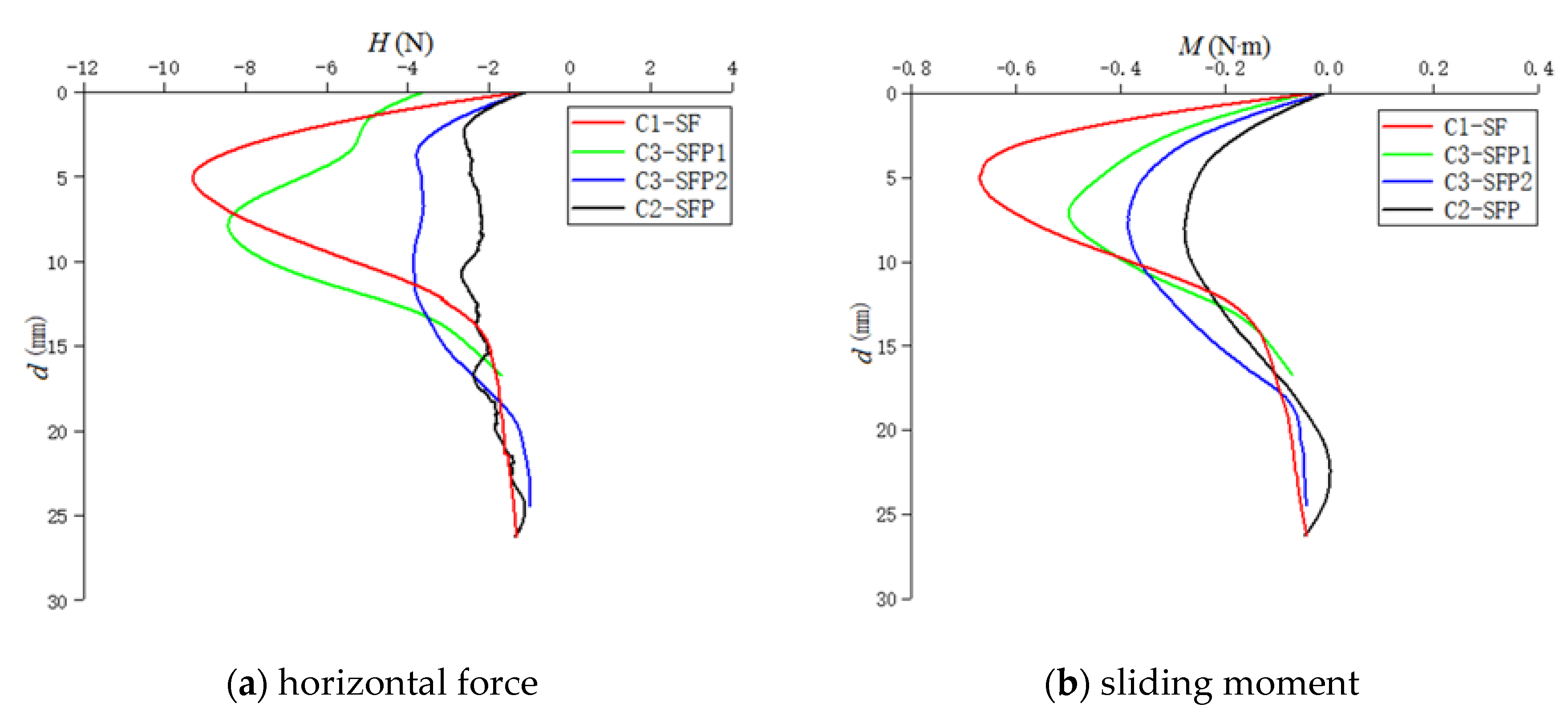
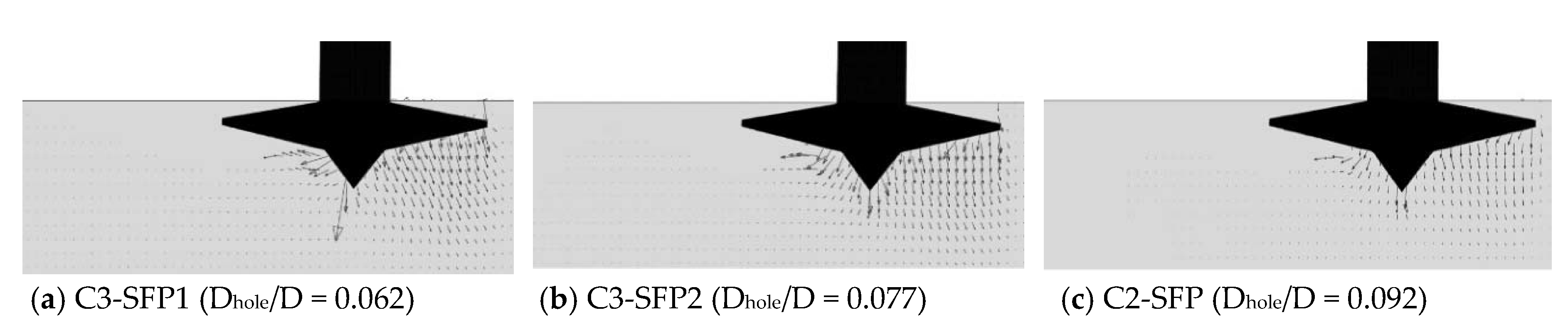
3.2. Effect of Borehole Diameter

Spudcan installation close to a footprint was investigated with different borehole diameters (i.e., Dhole = 0.062D, 0.077D and 0.092D, Groups C2 and C3 in Table 2). This parametric study aims to investigate the effects of the borehole diameter on the spudcan reinstallation process. The horizontal force H and the bending moment M at the spudcan reference point (LRP) are plotted against the penetration depth in Figure 6. As expected, the peak values of H and M in the case with perforation are smaller than those without perforation. Additionally, with the increase of borehole diameter, the induced horizontal force decreases gradually. It is also shown that the maximum bending moment at the LRP decreases with the borehole diameter. In the case with Dhole = 0.092D, the maximum horizontal force Hmax at the LRP is reduced by a ratio of 70%. The maximum bending moment Mmax also decreases by 60%.
Previous studies have shown that the horizontal sliding force is mainly comprised of two parts, i.e., the horizontal component of the contact force between the footprint and the spudcan base, and the lateral soil pressure on the spudcan side. Figure 7 shows the soil flow mechanism at the peak value of H and M under different borehole diameter conditions. In Figure 7a (Dhole = 0.062D), the soil velocity vector under the spudcan has a significant horizontal component, which induces the great potential of spudcan sliding. As the diameter of boreholes increases, Figure 7b,c show that the horizontal component gradually decreases. When Dhole = 0.092D, the soil velocity vector is almost vertically downward, indicating that the sliding risk is reduced. Furthermore, the soil flow field under the spudcan is more uniform than the other two cases, that is to say, the contact force under the spudcan is more uniform.

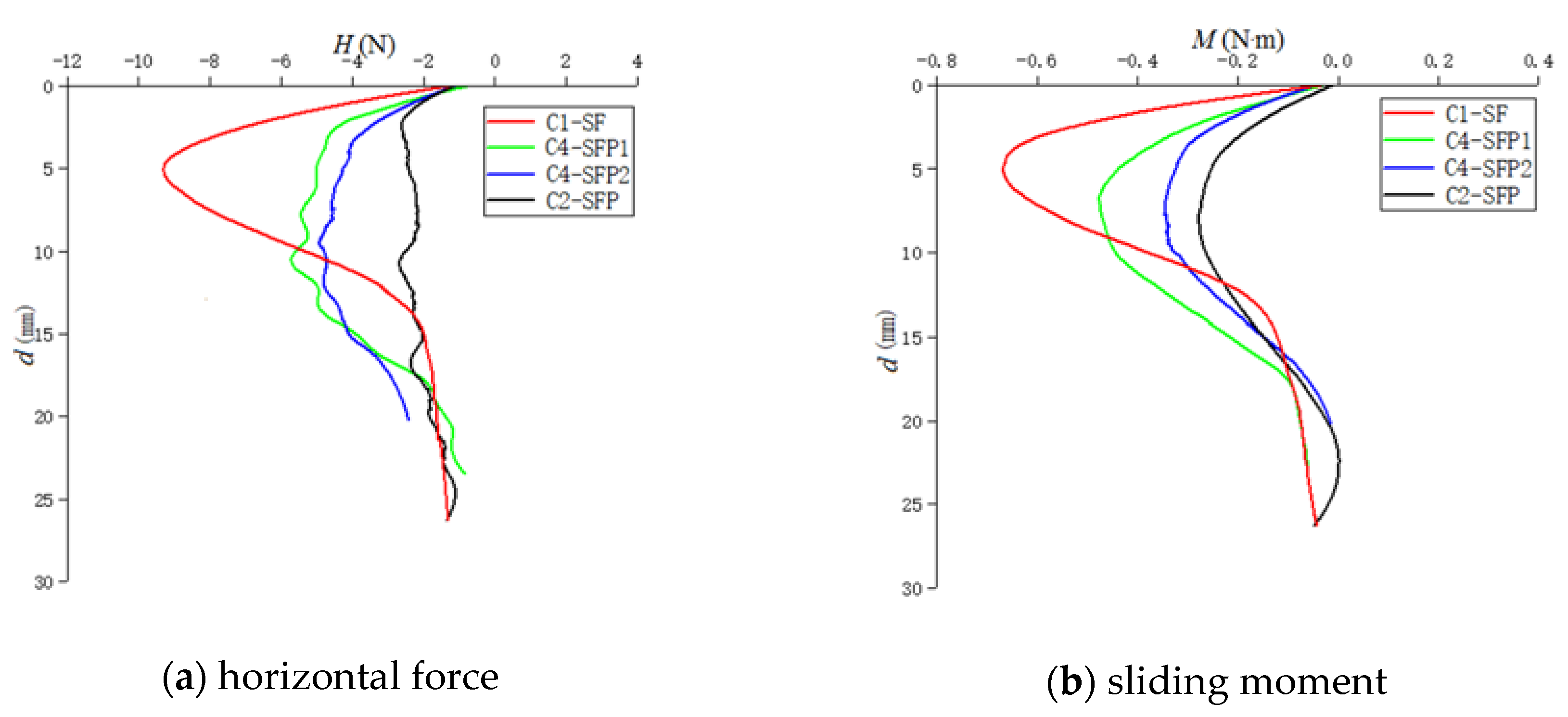
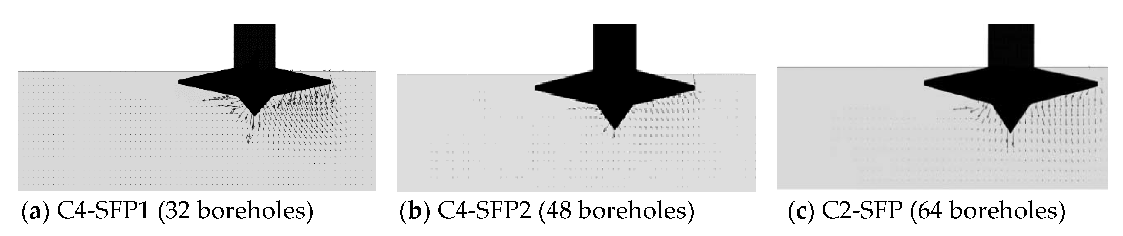
3.3. Effect of Borehole Number

Moreover, three cases are investigated to study the effect of borehole number, configured with 32, 48, and 64 boreholes, respectively (Groups C2 and C4, Table 2). Comparing the three cases with the base case, it is found that the peak value of H and M is reduced by 37% and 28.4%, respectively, for the case with the least number (C4-SFP1, Table 2). As the borehole number increases, the reduction ratio of the peak sliding loads increases. For the case with 64 boreholes, the Hmax and Mmax are reduced by 70% and 60%, respectively (see Figure 8).
The soil flow fields at the peak value of H and M in the cases with different borehole numbers are shown in Figure 9. In C2-SFP, the direction of soil flow under the spudcan is almost vertically downward, with the smallest horizontal velocity component. As the number of boreholes increases, the horizontal component of the velocity vector decreases. In the case with 32 boreholes (C4-SFP1, Table 2), the soil obviously produces a larger velocity vector and a larger horizontal component, which induces larger sliding loads on the spudcan (see Figure 9a). In short, the results show that the more boreholes there are, the smaller the peak value of the horizontal sliding force and bending moment are, that is, the better the sliding risk is mitigated.

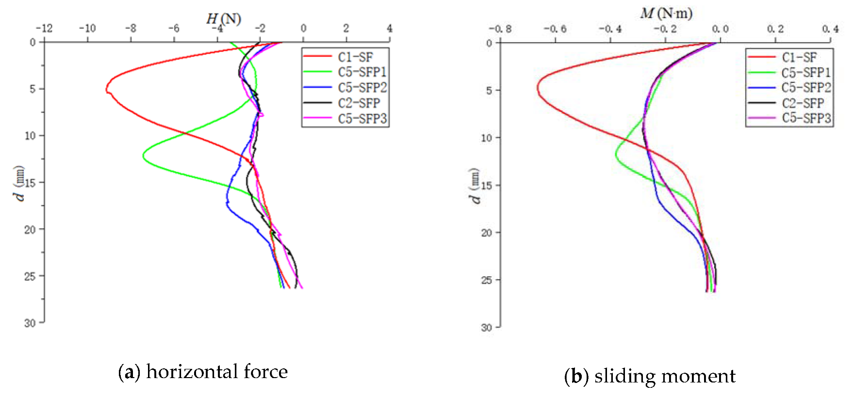
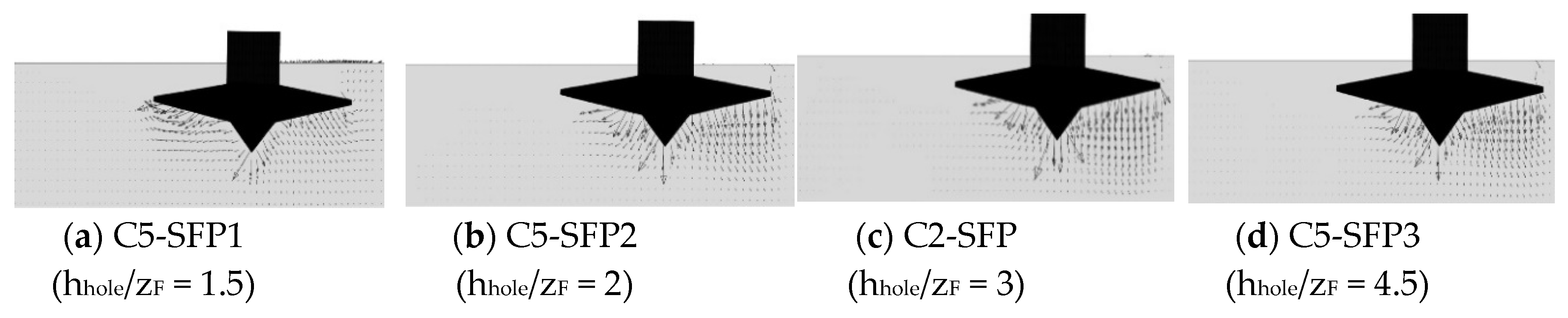
3.4. Effect of Borehole Depth

To investigate the effect of borehole depth on the mitigation efficiency, four cases with different borehole depths of 1.5zF, 2zF, 3zF, and 4.5zF (Groups C2 and C5 in Table 2) were simulated. The H and M in all the cases are plotted in Figure 10. When the borehole is relatively shallow (hhole = 1.5zF), the sliding force and moment are not significantly reduced. However, if the borehole is deeper, as for hhole = 2zF, the sliding loads are significantly reduced by 58–60%. It is worth noting that if the borehole depth continues to increase beyond 2zF, the H and M show little change. The effect of the borehole depth on the mitigation effect is explained by the flow mechanism around the spudcan, as shown in Figure 11. In the case with hhole =1.5zF, a significant horizontal velocity component is observed in the underneath soil, while it significantly decreases when hhole increases to 2zF. For the cases with hhole increasing beyond 2zF, the soil flow field shows little change (see Figure 11b–d).
In summary, with the borehole depth of hhole ≥ 2zF, it shows little influence on the effect of “perforation drilling” on reducing the bending moment and horizontal sliding force. In engineering practice, the borehole depth up to 2zF could be deep enough for sliding risk mitigation, which significantly reduces the operation task.

3.5. Effect of Drilling Range

The location of perforation boreholes could affect the soil flow mechanism under the spudcan, which greatly influences the mitigation efficiency. In order to determine the effect of drilling range on the sliding risk mitigation, comparative studies between three full-drilling cases (C2-SFP, C4-SFP1, and C4-SFP2) and corresponding semi-drilling cases (C6-SFP1, C6-SFP2, and C6-SFP3) with different borehole numbers were conducted. In the full-drilling case, both the inner and outer sides of the footprint are perforated, while only the outer side of the footprint is perforated in the semi-drilling case (see Figure 1). As shown in Figure 12a, the peak value of H shows little difference between the full-drilling and semi-drilling cases. However, it is followed by a much sharper reduction (between d = 0.1D and 0.3D) in the semi-drilling case. For the sliding moment M, a similar phenomenon is observed, as shown in Figure 12b. It is indicated that the semi-drilling configuration is more effective in mitigating sliding risks.
The soil flow mechanisms at different penetration depths were investigated with the full-drilling and semi-drilling cases with 32 boreholes (C4-SFP1 and C6-SFP1 in Table 2). Corresponding to the four depths marked in Figure 12, the soil velocity vector fields were plotted in Figure 13, in which the left column shows the full-drilling case. At d = 0.1D, when the horizontal force in the semi-drilling case reaches the peak (Figure 13a), its corresponding velocity field is almost identical to that of the full-drilling case. At d = 0.15D, the horizontal force in the full-drilling increases to its peak value, while the horizontal force in the semi-drilling case decreases sharply. At this depth, the soil distortion range and its velocity are more significant in the full-frilling case than the semi-drilling case (Figure 13b). This explains why the Hmax is reduced more sharply in the semi-drilling case. As the spudcan penetrates to d = 0.3D, the horizontal sliding force in both cases significantly reduces, while the full-drilling case is a little larger than the semi-drilling case. This is because that the soil velocity is slightly larger in the full-drilling case (Figure 13c). When the spudcan penetrates beyond 0.37D, the velocity fields in the two cases show little difference. The flow mechanism in the two cases clearly explains that the efficiency of semi-drilling is close to that of full-drilling, and even better.
Additionally, it can be explained in a simpler way. For the spudcan installed close to a footprint, the underneath soil can be divided into a weak side and a strong side, which are located in the inner and outer side of the footprint, respectively. The semi-drilling only weakens the strong side, while the full-drilling weakens both sides. With semi-drilling, the underneath soil strength is more symmetric than that of full-drilling. As the asymmetricity of underneath soil strength is the main cause of sliding risks, the mitigation effect of the semi-drilling is more significant. Considering the difficulty and complexity of the perforation drilling operation, it is recommended to only drill holes on the outer side of the footprint.

4. Conclusions

A CEL large-deformation finite element model was established to study the effect of perforation drilling on reducing the sliding risk during spudcan installation close to footprints. The influences of parameters, such as the borehole diameter, number, depth, and the drilling range, were studied. Generally, the following conclusions were drawn:
(1)
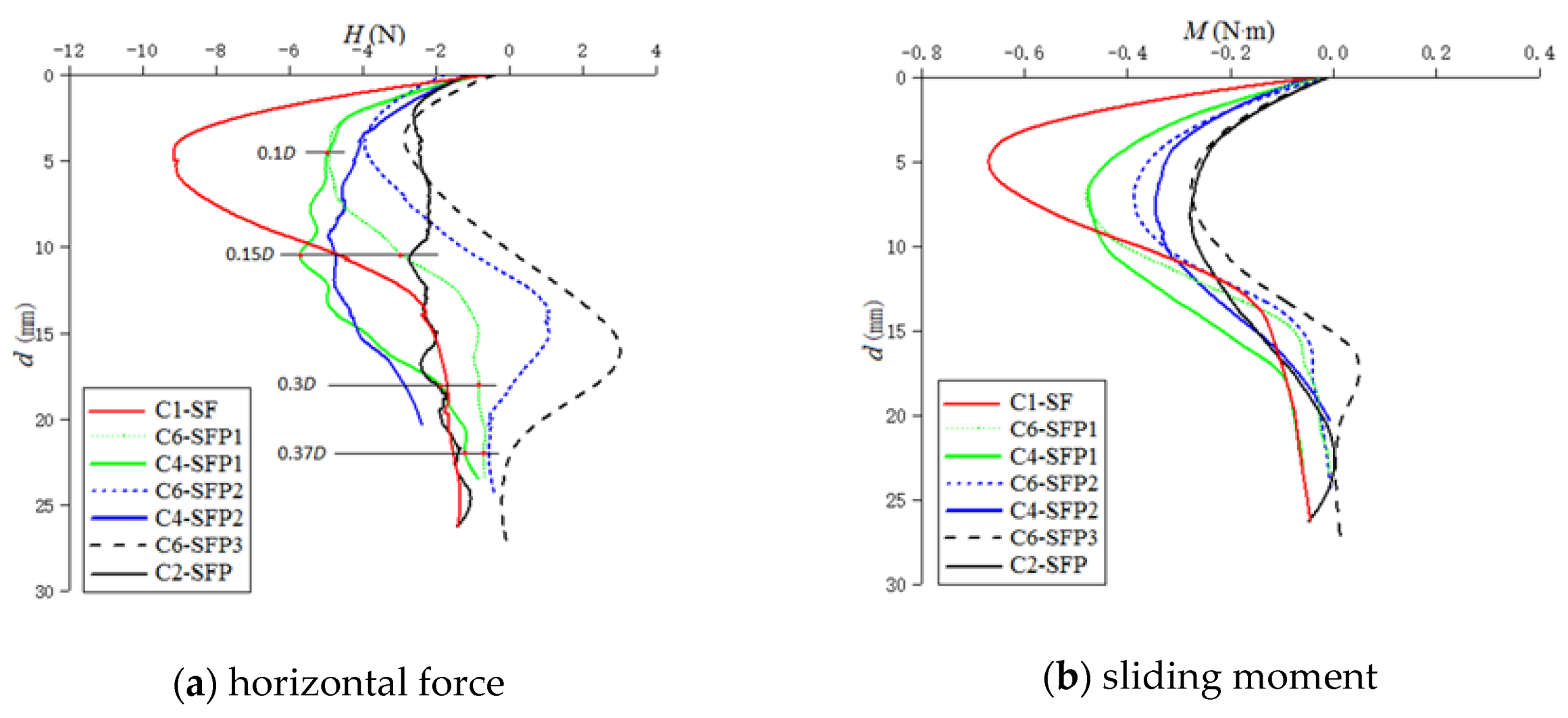
The CEL model is effective in simulating the spudcan installation close to footprints with perforation drilling. During the spudcan installation close to footprints, the induced sliding moment and horizontal force increases and reaches the peak values, followed by a reduction. With proper configuration, the perforation drilling method can significantly reduce the peak sliding loads.
(2)
The larger the borehole diameter and the borehole number are, the smaller the bending moment and horizontal force acting on the spudcan are, indicating higher efficiency in mitigating the sliding risk. The perforation drilling with 64 boreholes of Dhole/D = 0.092 significantly reduces the maximum bending moment and horizontal force by 60% and 71%, respectively.
(3)
The mitigation efficiency increases with the borehole depth. However, it shows little improvement when the borehole depth is deeper than 2zF. Therefore, an optimal perforation drilling depth of 2zF is recommended in the engineering practice.
(4)
The semi-drilling is more effective in mitigating sliding risks than the full-drilling. The main reason is that the semi-drilling only weakens the strong side in the soil under the spudcan, while the full-drilling simultaneously weaken both the strong and weak side. Considering the significant costs of perforation drilling in the engineering practice, it is recommended to perform semi-drilling on the outer side of the footprint for sliding risk mitigation.

Author Contributions

Conceptualization, P.G. and D.S.; Data curation, X.F.; Formal analysis, K.Y.; Investigation, Z.L.; Methodology, P.G.; Software, Z.L.; Supervision, D.S.; Validation, Z.L.; Writing—original draft, P.G.; Writing—review and editing, D.S. All authors have read and agreed to the published version of the manuscript.

Funding

This research and the APC were funded by the National Natural Science Foundation of China, grant number 51709164 and 41772273.

Acknowledgments

This support is gratefully acknowledged, as is the assistance of the English improvement, Mac Darlington Uche Onuoha from China University of Petroleum.

Conflicts of Interest

The authors declare no conflict of interest.

References

  1. Stewart, D.P.; Finnie, M.S. Spudcan–Footprint Interaction During Jack–Up Workovers. In Proceedings of the Eleventh International Offshore and Polar Engineering Conference. International Society of Offshore and Polar Engineers, Stavanger, Norway, 17–22 June 2001. [Google Scholar]
  2. Cassidy, M.J.; Quah, C.K.; Foo, K.S. Experimental Investigation of the Reinstallation of Spudcan Footings Close to Existing Footprints. J. Geotech. Geoenviron. Eng. 2009, 135, 474–486. [Google Scholar] [CrossRef]
  3. Gan, C.T. Centrifuge Model Study on Spudcan-Footprint Interaction. Ph.D. Thesis, National University of Singapore, Singapore, 2009. [Google Scholar]
  4. Gan, C.T.; Leung, C.F.; Cassidy, M.J.; Gaudin, C.; Chow, Y.K. Effect of time on spudcan- footprint interaction in clay. Géotechnique 2012, 62, 401–413. [Google Scholar] [CrossRef]
  5. Gaudin, C.; Kong, V.; Cassidy, M. An Overview of Spudcan Reinstallation Near a Footprint. In Proceedings of the Offshore Technology Conference, Houston, TX, USA, 30 April–3 May 2012. [Google Scholar]
  6. Kong, V.; Cassidy, M.J.; Gan, C.T. Experimental study of the effect of geometry on reinstallation of jack-up next to footprint. Can. Geotech. J. 2013, 50, 557–573. [Google Scholar] [CrossRef]
  7. Kong, V.; Cassidy, M.J.; Gaudin, C. Failure mechanisms of a spudcan penetrating next to an existing footprint. Theor. Appl. Mech. Lett. 2015, 5, 64–68. [Google Scholar] [CrossRef] [Green Version]
  8. Fang, Y.S.; Liu, C.; Shih, Y.C. Re-Penetration of a Spudcan on Sand Near an Existing Footprint. J. Geoengin. 2019, 14, 141–154. [Google Scholar]
  9. Yuan, Y.; Zhang, Y.; Zhang, C.; Fan, L.; Duan, M. Three-legged Jack-up unit Scale Model Experiment Study of Spudcan Reinstallation Close to Footprint. In Proceedings of the 29th International Ocean and Polar Engineering Conference. International Society of Offshore and Polar Engineers, Honolulu, HI, USA, 16–21 June 2019; pp. 2049–2054. [Google Scholar]
  10. Mao, D.F.; Zhang, M.H.; Zhang, L.B.; Duan, M.L.; Song, L.S. Sliding risk of jack-up platform re-installation close to existing footprint and its countermeasure. Pet. Explor. Dev. 2015, 42, 233–237. [Google Scholar] [CrossRef]
  11. Zhang, W. Investigation of Spudcan-Footprint Interaction in Clay with a Novel Implementation of a Three–Dimensional Large Deformation Finite Element Method. Ph.D. Thesis, The University of Western Australia, Perth, Australia, 2018. [Google Scholar]
  12. Yu, L.; Zhang, H.Y.; Li, J.; Wang, X. Finite Element Analysis and Parametric Study of Spudcan Footing Geometries Penetrating Clay Near Existing Footprints. J. Mar. Sci. Eng. 2019, 7, 175. [Google Scholar] [CrossRef] [Green Version]
  13. Zheng, J.; Wang, D. Numerical investigation of spudcan-footprint interaction in non-uniform clays. Ocean. Eng. 2019, 188, 106295. [Google Scholar] [CrossRef]
  14. Jun, M.J.; Kim, Y.H.; Hossain, M.S.; Cassidy, M.J.; Hu, Y.; Park, S.G. Global jack-up rig behaviour next to a footprint. Mar. Struct. 2019, 64, 421–441. [Google Scholar] [CrossRef]
  15. Dean, E.T.R.; Serra, H. Concepts for mitigation of spudcan-footprint interaction in normally consolidated clay. In Proceedings of the Fourteenth International Offshore and Polar Engineering Conference. International Society of Offshore and Polar Engineers, Toulon, France, 23–28 May 2004; pp. 721–728. [Google Scholar]
  16. Hossain, M.S.; Stainforth, R.; Ngo, V.T.; Cassidy, M.J.; Kim, Y.H.; Jun, M.J. Experimental investigation on the effect of spudcan shape on spudcan-footprint interaction. Appl. Ocean Res. 2017, 69, 65–75. [Google Scholar] [CrossRef]
  17. Jun, M.J.; Hossain, M.S.; Cassidy, M.J.; Hu, Y.; Park, S.G. Physical and numerical modelling of novel spudcan to ease spudcan-footprint interactions. In Proceedings of the 28th International Ocean and Polar Engineering Conference. International Society of Offshore and Polar Engineers, Sapporo, Japan, 10–15 June 2018; pp. 557–561. [Google Scholar]
  18. Jun, M.J.; Kim, Y.H.; Hossain, M.S.; Cassidy, M.J.; Hu, Y.; Sim, J.W. Numerical investigation of novel spudcan shapes for easing spudcan-footprint interactions. J. Geotech. Geoenvironmental Eng. 2018, 144, 4018055. [Google Scholar] [CrossRef] [Green Version]
  19. Jun, M.J.; Kim, Y.H.; Hossain, M.S.; Cassidy, M.J.; Hu, Y.; Park, S.G. Optimising spudcan shape for mitigating horizontal and moment loads induced on a spudcan penetrating near a conical footprint. Appl. Ocean Res. 2018, 79, 62–73. [Google Scholar] [CrossRef]
  20. Hossain, M.S.; Dong, D.; Gaudin, C.; Kong, V.W. Skirted spudcans and perforation drilling for installation of spudcans close to existing footprints. In Proceedings of the Offshore Site Investigation and Geotechnics: Integrated Technologies-Present and Future. Society of Underwater Technology, London, UK, 12–14 September 2012; pp. 597–605. [Google Scholar]
  21. Hossain, M.S.; Stainforth, R. Perforation drilling for easing spudcan-footprint interaction issues. Ocean Eng. 2016, 113, 308–318. [Google Scholar] [CrossRef] [Green Version]
  22. Brennan, R.; Diana, H.; Stonor, R.W.P. Installing jackups in punch-through-sensitive clays. In Proceedings of the Offshore Technology Conference, Houston, TX, USA, 1–4 May 2006. [Google Scholar]
  23. Chan, N.H.C.; Paisley, J.M.; Holloway, G.L. Characterization of soils affected by rig emplacement and Swiss cheese operations-Natura Sea, Indonesia, a case study. In Proceedings of the 2nd Jack-up Asia Conference and Exhibition, Singapore, 17–18 November 2008. [Google Scholar]
  24. Hartono, H.; Tho, K.; Leung, C.; Chow, Y. Centrifuge and Numerical Modelling of Reaming as a Mitigation Measure for Spudcan–Footprint Interaction. In Proceedings of the Offshore Technology Conference—Asia: Offshore Technology Conference, Kuala Lumpur, Malaysia, 25–28 March 2014; pp. 1478–1492. [Google Scholar]
  25. Qiu, G.; Henke, S.; Grabe, J. Application of a coupled Eulerian–Lagrangian approach on geomechanical problems involving large deformations. Comput. Geotech. 2011, 38, 30–39. [Google Scholar] [CrossRef]
  26. Tho, K.K.; Leung, C.F.; Chow, Y.K.; Swaddiwudhipong, S. Eulerian finite- element technique for analysis of jack-up spudcan penetration. Int. J. Geomech. 2012, 12, 64–73. [Google Scholar] [CrossRef]
  27. Wang, D.; Bienen, B.; Nazem, M. Large deformation finite element analyses in geotechnical engineering. Comput. Geotech. 2015, 65, 104–114. [Google Scholar] [CrossRef]
Figure 1. Schematic diagram of spudcan installation close to the footprint with perforation drilling.
Jmse 08 00118 g001
Figure 2. Finite element model of the soil with a footprint and perforation boreholes in ABAQUS.
Jmse 08 00118 g002
Figure 3. Comparison of the numerical and experimental results in the cases without and with drilling. (SF): spudcan test adjacent to a footprint; (SFP): spudcan test adjacent to a perforated footprint).
Jmse 08 00118 g003
Figure 4. Soil deformation at different depths in both perforated (C2-SFP) and un-perforated (C1-SF) cases.
Jmse 08 00118 g004aJmse 08 00118 g004b
Figure 5. Soil flow fields at different penetration depths in both perforated (C2-SFP) and un-perforated (C1-SF) cases.
Jmse 08 00118 g005
Figure 6. Sliding loads on the spudcan installed close to footprints with different borehole diameters.
Jmse 08 00118 g006
Figure 7. Soil flow fields at depths of peak H and M in cases with different borehole diameters.
Jmse 08 00118 g007
Figure 8. Sliding loads on the spudcan installed close to footprints with different borehole numbers.
Jmse 08 00118 g008
Figure 9. Soil flow fields at depths of peak H and M in cases with different borehole numbers.
Jmse 08 00118 g009
Figure 10. Sliding loads on the spudcan installed close to footprints with different borehole depths.
Jmse 08 00118 g010
Figure 11. Soil flow fields at depths of peak H and M in cases with different borehole depths.
Jmse 08 00118 g011
Figure 12. Sliding loads on the spudcan installed close to footprints with different perforation drilling ranges.
Jmse 08 00118 g012
Figure 13. Soil flow fields at different spudcan penetration depths in the full-drilling and semi-drilling cases.
Jmse 08 00118 g013aJmse 08 00118 g013b
Table 1. Soil parameters in the FEM model.
PropertyValue
Soil effective unit weight, γ (kN/m3)7
Internal friction angle, φ (°)0
Dilatancy angle, ψ (°)0
Undrained shear strength, su (kPa)6
Elastic Modulus, E(kPa)500 su
Poisson’s ratio, υ0.49
Table 2. Parameters of numerical simulation cases.
Numerical CasesDhole/Dhhole/zFNumber of DrillingRange of Drilling
C1-SF000
C2-SFP0.092364Full-drilling
C3-SFP10.062364Full-drilling
C3-SFP20.077364Full-drilling
C4-SFP10.092332Full-drilling
C4-SFP20.092348Full-drilling
C5-SFP10.0921.564Full-drilling
C5-SFP20.092264Full-drilling
C5-SFP30.0924.564Full-drilling
C6-SFP10.092332Semi-drilling
C6-SFP20.092348Semi-drilling
C6-SFP30.092364Semi-drilling

