Article

Research on the Bearing Capacity of a Damaged Jacket Repaired by a Grouting Clamp Based on a Type of Wedge Gripping

1
College of Mechanical and Electrical Engineering, Harbin Engineering University, Harbin 150001, China
2
School of Mechanical Engineering, Hebei University of Technology, Tianjin 300130, China
*
Author to whom correspondence should be addressed.
J. Mar. Sci. Eng. 2020, 8(12), 973; https://doi.org/10.3390/jmse8120973
Submission received: 26 October 2020 / Revised: 22 November 2020 / Accepted: 23 November 2020 / Published: 30 November 2020
(This article belongs to the Special Issue Coastal Engineering: Sustainability and New Technologies)

Abstract

:
In the process of repairing a damaged jacket with a grouting clamp, it is necessary to analyze the bearing capacity of the damaged structure to determine whether it meets requirements for maintenance and reinforcement. On the basis of previous research results, this paper proposes a design scheme of a grouting clamp based on wedge gripping, which can effectively improve the local bearing capacity of the jacket by more than 35%. The elastic–plastic theory was used to analyze the bearing capacities of steel pipe piles under three different conditions (ideal steel pipe, bending steel pipe and steel pipe with a defective section) and with reinforcement by a grouting hoop. The bearing capacity of the mechanical grouting clamp was analyzed, and the resulting theoretical design was verified by a bearing performance experiment. The results support the conclusion that the wedge mechanical grouting clamp can effectively strengthen local jacket members.

1. Introduction

Over the 21st century, oil and gas reserves on land have been rapidly depleted, and marine environments are thus increasingly explored to obtain these resources. Many of the world’s offshore platforms are approaching or have exceeded their design life. At present, more than 50% of the offshore facilities on the Norwegian continental shelf (NCS), the British continental shelf (UKCS) and the Gulf of Mexico continental shelf have exceeded their original service lives [1]. Currently, the most commonly repaired component of offshore platforms is the grouting clamp because this strategy is characterized by effectiveness, convenient construction and low cost [2]. Therefore, this type of maintenance technology has received extensive attention from experts around the world.
In the past two decades, countries such as the United States, the United Kingdom, Norway and Japan have invested considerable research efforts into the repair and reinforcement of damaged components of offshore platforms, and several breakthroughs have been made [3]. From 1985 to 1987, the Elnashai team of the Imperial College of Technology completed an experimental mechanical study on the pressure grouting clamp for the first time. In 1989, Shuttleworth F P and Billington C J et al. in Britain analyzed the prestressed grouting connection of an offshore structural steel pipe. A small model was used to test the shrinkage of grouting, the initial creep in the grouting ring and the long-term shrinkage creep [4]. In 2002, Grundy Paul and Yee Teck Lee of Monash University in Australia carried out a study on the bearing capacity of grouting clamps with a shear key structure under dynamic load [5]. In 2003, the team of Jin Weiliang and Gong Shunfeng of Zhejiang University confirmed through research that the grouting repair and reinforcement scheme could improve the bearing capacity of the damaged components of the studied platform [6]. In 2006, Zhao Xiaolin’s team from Monash University in Australia analyzed and studied the bearing capacity of grouting clamps under a harsh environment [7]. In 2007, a K-type grouting clamp was designed for an ocean environment. The annular space between the clamp and the damaged parts was filled with cement. In this case, both ends of the clamp needed to be sealed to avoid the corrosion of cement by seawater [8]. In 2010, the team of Shi Xiang and Yang Bin from the Ocean University of China analyzed the traditional self-stress grouting clamp and proposed a new type of expansion pressure self-stress grouting clamp [9]. In 2011, Jiang Shouchao of Tongji University and colleagues summarized the latest developments in grouting pile-to-casing connections and characterized their mechanical properties under axial, combined and cyclic loads [10]. In 2013, Samarakoon, S.M.S.M.K and colleagues of the Singapore University of Technology highlighted the wide use of grouting repair for offshore platforms and explained the latest developments in grouting connections and their advantages and disadvantages relative to the welding or mechanical connection [11]. In 2014, Li Cong and others from the Ocean University of China designed a shorter bolt-type expansion grouting clamp with a simpler structure, aiming to address the complicated structure and installation of the long bolt-type expansion grouting clamp. In 2015, Advanced Composite Structures Australia Co., Ltd., developed the composite clamp with Petronas [12]. In 2016, researchers from Petronas, such as Sum W S, Leong K H and colleagues, conducted a further study on the use of composite clamps to repair damaged pipelines. Based on the optimization of the finite element model, a method of designing clamps for different pipe diameters was developed [13]. In 2017, Jeong Hwa Lee’s team from Korea University conducted concentric and eccentric load tests on the grouting connection of piles and casings of an offshore oil platform and natural gas platform [14]. In the same year, Shi Xiang, Jiao Guoyang and colleagues from the Ocean University of China tested and analyzed the load-bearing performance of a large-size expansion clamp model [15]. In 2018, Norwegian researchers Gunnar Soland and AtlE Johansen et al. summarized the current design rules of the grouting pile sleeve connection, carried out compression and tension axial load experiments on the grouting clamp and proposed a new design formula [16]. In 2018, Norwegians Johansen, A., Solland, G. and colleagues conducted a study on the grouting connection with shear keys of an offshore sheathed platform and determined its axial bearing capacity under cyclic load [17]. In 2019, Chellappan, N. Vignesh and colleagues from the Indian Institute of Technology conducted a comprehensive study on the load transfer between the two parts of a tubular member connected by a fractured grouting joint. The axial tension and moment loads were simulated [18].
In view of the previous achievements of different research institutions, this paper proposes a new type of wedge gripping for the grouting clamp. First, the bearing capacities of an ideal steel pipe, bending steel pipe, steel pipe with a defective section and a steel pipe pile reinforced by a grouting clamp were analyzed. Second, the bearing capacity of the mechanical grouting clamp was evaluated, and the ability of the grouting clamp to repair the damaged jacket was established. Finally, the effectiveness of the mechanical grouting clamp in strengthening the jacket members was verified by experiments.

2. Analysis of the Bearing Capacity of a Damaged Steel Pipe Pile

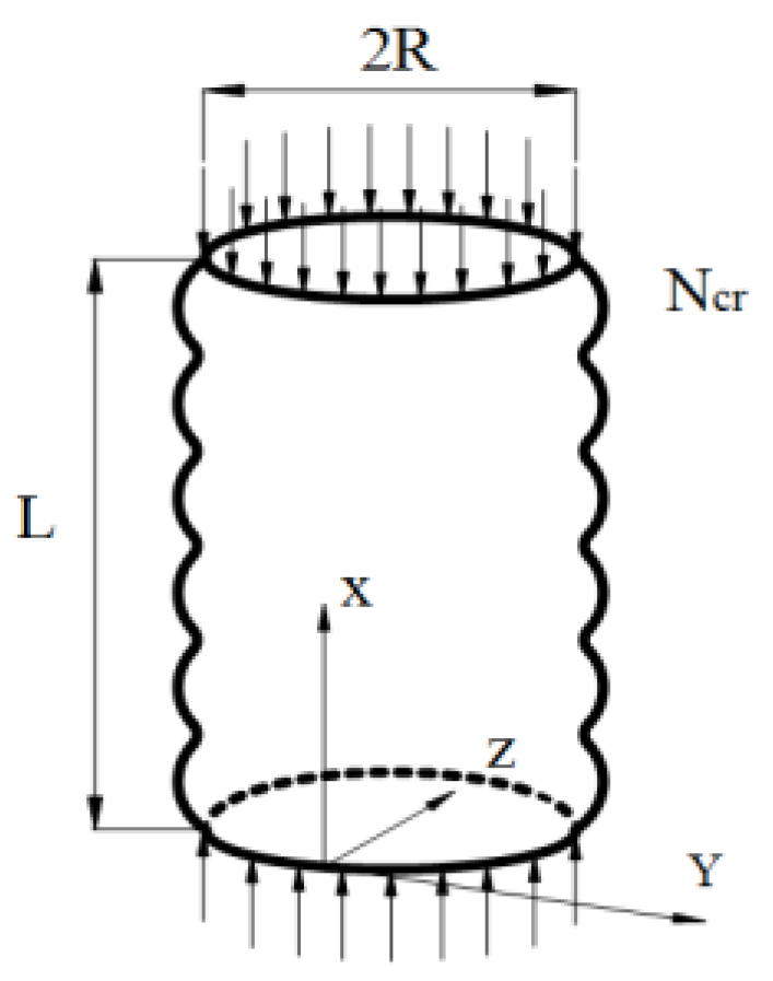
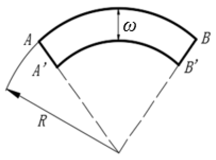
2.1. Buckling Analysis of an Ideal Steel Tubular Pile Under Axial Compression

Assuming that the jacket steel pipe is subjected to uniform axial pressure, its buckling deformation is as shown in Figure 1: uniform axial pressure is applied to the steel pipe, and the Karman–Donnell nonlinear buckling equation is used to obtain the solution [19].
U 8 ω 4 ( P x 2 ω x 2 + P y 2 ω y 2 + 2 P x y 2 ω x y ) + E t R 2 4 ω x 4 = 0
Here, R is the shell radius, t is the shell thickness, L is the shell length, E is the elastic modulus, U is the bending rigidity, U = ( E t 3 ) / [ 12 ( 1 μ 2 ) ] , μ is Poisson’s ratio, Px is the axial load, Py is the transverse load, and ω is the lateral displacement, as shown in Figure 2.
▽ is the Hami operator, the 4th and 8th orders of which are calculated as follows:
4 = ( 4 x 4 + 2 4 x 2 y 2 + 4 y 4 ) ,
8 = ( 8 x 8 + 4 8 x 6 y 2 + 6 8 x 2 y 6 + 8 y 8 ) .
Because the steel tube is only subjected to axial load (only Px), P x = σ x t . Equation (1) can be written as follow:
U 8 ω + σ x t 4 2 ω x 2 + E t R 2 4 ω x 4 = 0
Before calculating the critical stress, the mode of lateral displacement ω is assumed to be as follow:
ω = ω 0 sin m π x L sin n y R ,
where m is the half-wave number in the x-direction, n is the half-wave number in the y-direction, and ω0 is the maximum deflection value.
In order to simplify the calculation, let β = mπR/L; then,
σ x = U β 2 t R 2 + E β 2
For the analysis in this paper, the critical stress of the steel pipe is required. Equation (3) is derived from β, and the result is zero. The calculated σx is the minimum value, which is the critical stress; the result is as follow:
β 4 = E t R 2 U
When Equation (4) is introduced into Equation (3), the critical stress of the thin cylindrical shell under axial compression can be obtained as follows:
σ c r = 1 3 ( 1 μ 2 ) E t R
In order to avoid local buckling of the thin-walled steel pipe before yielding, the yield stress of the steel must be fy ≤ σcr, D = 2R, and Equation (5) can be obtained as follows:
D / t 1072 235 f y

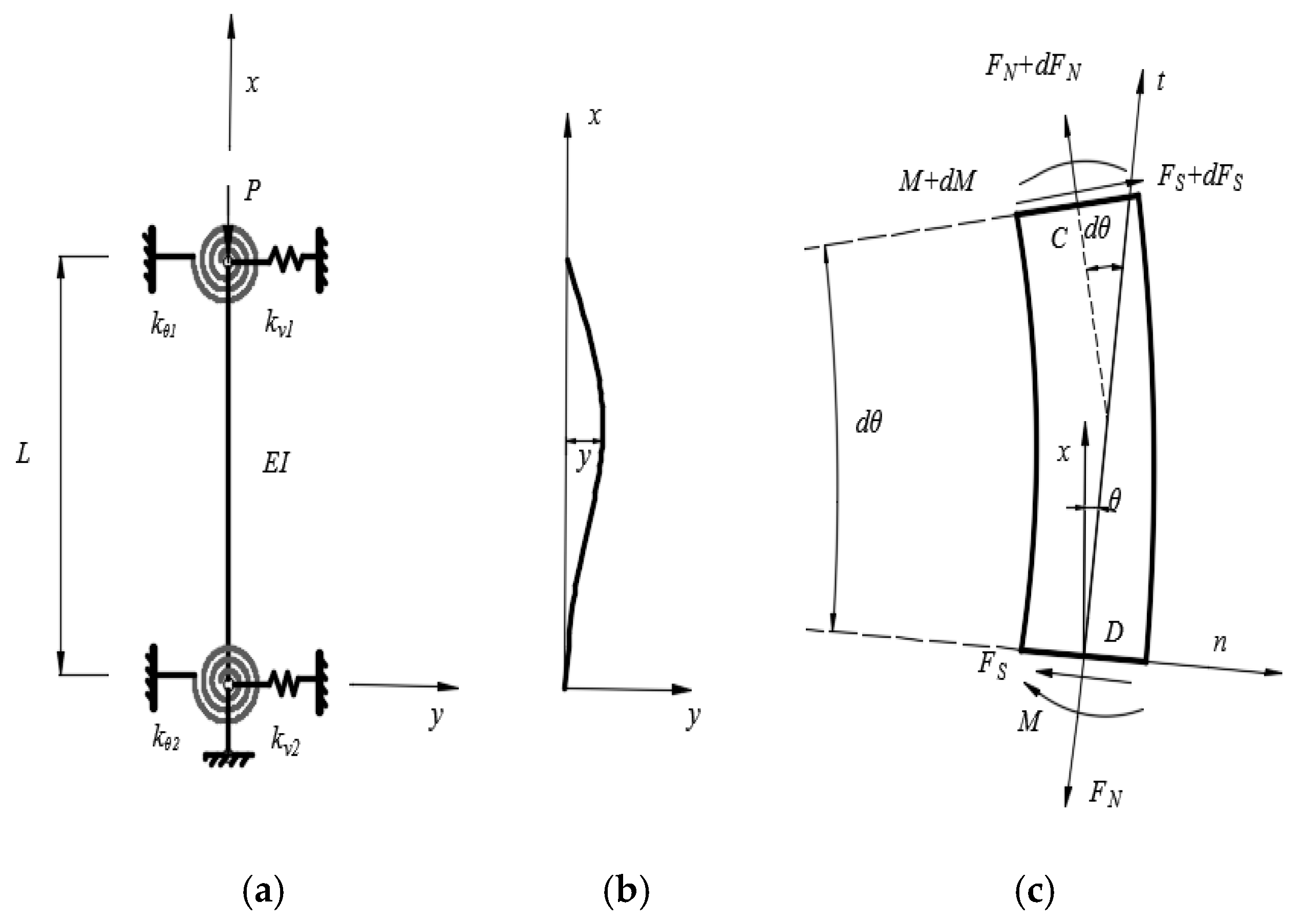
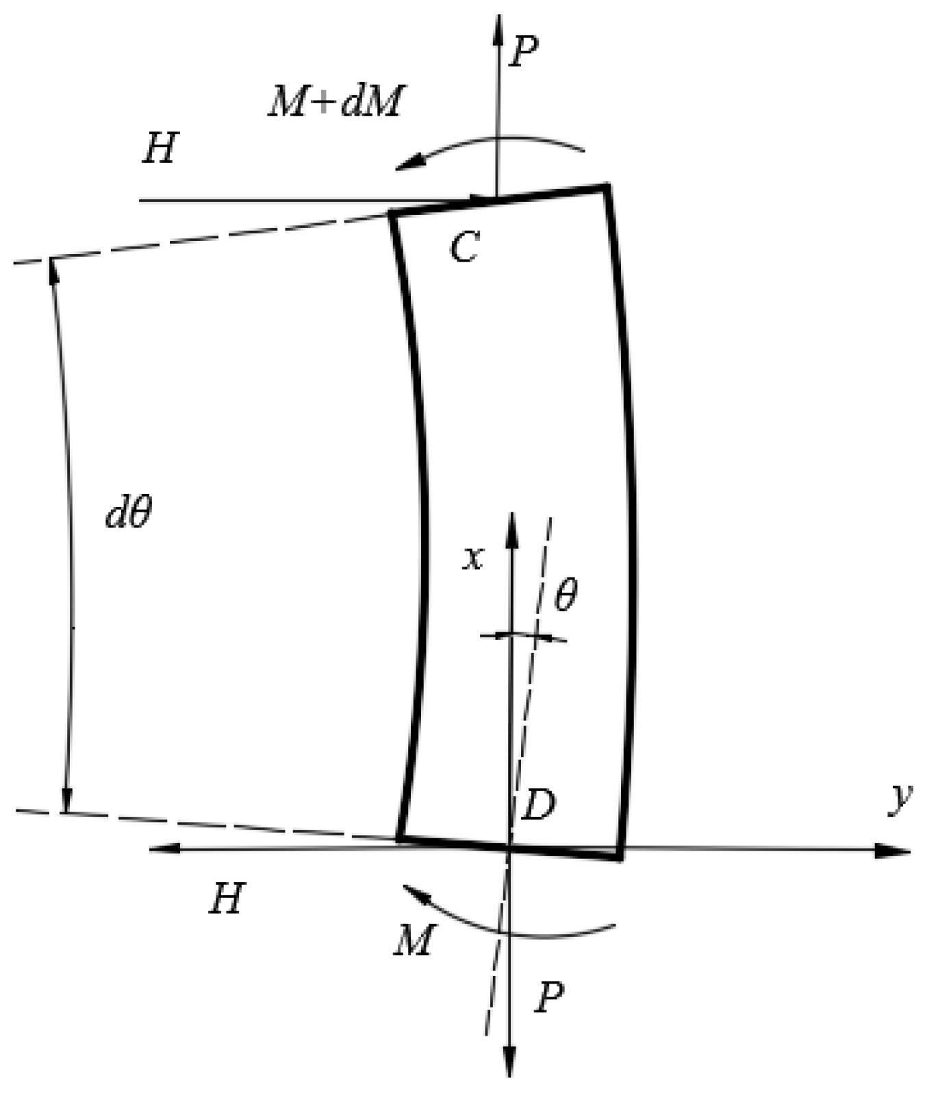
2.2. Buckling Analysis and Horizontal Bearing Capacity Analysis of a Bending Steel Tubular Pile under Axial Compression

When the axial compression bar is subjected to a force with a pressure load of P, it is assumed that the deformation of the bar is a small deflection bending deformation, and the size and direction of the axial compression P remain unchanged, as shown in Figure 3a,b. The upper end is restrained by an anti-rotation spring and horizontal tension-compression spring, with stiffnesses of kθ1 and kv1, respectively; the lower end of the rod has an anti-rotation spring with a stiffness of kθ2, a horizontal tension-compression spring with a stiffness of kv2 and a vertical rigid hinge.
The equilibrium equation is established according to Figure 3c: ∑MC = 0.
d M + ( F S sin θ F N cos θ ) d y ( F N sin θ + F S cos θ ) d x = 0
According to the equivalence of the force system, the force is equivalent to H parallel to the x-axis and P parallel to the y-axis, as shown in Figure 4.
{ P = F N cos θ F s sin θ H = F N sin θ + F S cos θ
By applying the bending moment formula and the bending equation EIy = −M under a small disturbance to the above formula, three differential equations of the steel pipe pile can be obtained:
E I y + P y + H = 0
According to Equation (9) and the bending equation, the boundary conditions of the end of the jacket pile with elastic constraints corresponding to x = 0 and x = l are established:
When   x   =   0 ,   { E I y + P y + k v 2 y = 0 E I y k θ 2 y = 0
When   x   =   l ,   { E I y + P y k v 1 y = 0 E I y k θ 1 y = 0
with the order kv1/EI = α1, kθ1/EI = β1, kv2/EI = α2, kθ2/EI = β2, P/EI = k2, and u = kl. According to its general solution, the following equation can be obtained:
{ ( α 1 + α 2 ) ( u l ) 6 + [ β 1 β 2 ( α 1 + α 2 ) α 1 α 2 l ] ( u l ) 4 α 1 α 2 ( β 2 + β 1 β 2 l + β 1 ) ( u l ) 2 } sin u + [ ( α 1 + α 2 ) ( β 1 β 2 ) ( u l ) 5 + α 1 α 2 l ( β 2 β 1 ) ( u l ) 3 2 α 1 α 2 β 1 β 2 u l ] cos u + 2 α 1 α 2 β 1 β 2 u l = 0
In order to obtain the solution of the above equation, the coefficients before each variable function must be determined. By changing the stiffness of the support at one end of the jacket pile, different constraint conditions at both ends of the jacket pile can be obtained.
When α1 = α2 = ∞, there is no lateral displacement at the end of the jacket pile; when α1 = α2 = 0, there is no lateral constraint at the end of the jacket pile; when β1 = β2 = ∞, there is no change in the angle of the jacket pile; when β1 = β2 = 0, there is no rotation constraint at the end of the jacket pile.
The lateral bearing capacity of the steel pipe pile is mainly determined by the bending bearing capacity of the plastic hinge area of the steel pipe pile section. The diameter and material of the steel pipe pile determine the bending capacity of the plastic hinge area. When the plastic hinge is present in the structure, all parts except for the plastic hinge area can be regarded as rigid bodies [20,21].
As shown in Figure 5, it is assumed that the force and moment conservation equations of the steel tube column are applied under the condition of full-section yield:
{ f y s ( 2 π 4 Φ ) r p δ = N 2 Φ r p δ f y s ( x 2 c + x 1 ) + 2 ( π Φ ) r p δ f y s ( x 1 c x 1 ) = M
where fys is the yield strength of steel with defects, which generally refer to corrosion defects in this analysis; Φ is the angle between the intersection line of the neutral axis and the steel pipe and the loading direction; rp is the inner radius of the steel pipe; δ is the thickness of the steel pipe; N is the axial force; x1 is the offset of the neutral axis; x1c is the displacement of the centroid axis in the area under tension; and x2c is the displacement of the centroid axis in the compression area. The horizontal bearing capacity of the bending steel pipe pile can be obtained from the data.

2.3. Ultimate Bending Moment and Axial Bearing Capacity of a Steel Pipe Pile with a Defective Section

When the jacket is damaged, defects are produced. It is assumed that the defect is a circular arc and that the rest is the steel pipe with a constant radius [6,20]. The defect leads to a change in the inertia of the section and the movement of the neutral axis, which results in the loss of strength. It is assumed that the axial length of the defective section is the same as that of the ideal section, and the defect does not change the equal area axis of the section. As shown in Figure 6, the defect depth δ is as follow:
δ R p = 1 + π [ cos α cos ( α + sin α 2 ) ] α + sin α
where δ is the defect depth, Rp is the outer radius of the steel pipe, and α is the angle from the center of the deformed circle to the defect and the Z-axis.
Considering the center of the deformed circle as the origin, the ultimate bending moment of the defective section is as follow:
M = 2 σ y t p r 2 [ 2 sin β sin α ( 1 + cos α ) ]
where σy is the yield limit, Rp is the outer radius of the steel pipe, tp is the wall thickness, and r is the radius after deformation.
When calculating the axial bearing capacity of the defective section, the area converted under the impact load is determined first:
A 1 = A π θ π
The tensile capacity of the defective steel pipe is as follow:
F p = F t A 1
The compressive bearing capacity of the defective steel pipe is as follow:
F c p = F c t A 1
Fct in the above formula is as follow:
F c t = [ 1 ( K l / r p ) 2 2 C c ] σ y 5 3 + 3 ( K l / r p ) 8 C c ( K l / r p ) 3 8 C c K l / r p < C c
F c t = 12 π 2 E 23 ( K l / r p ) 2 K l / r p C c
C c = ( 12 π 2 E σ y ) 1 2
where Ft is the allowable tensile strength, Fct is the allowable compressive strength, K is the effective length coefficient, l is the unsupported length, rp is the inner diameter of the steel pipe, and E is the modulus of elasticity and equal to 206 GPa.
As shown in Figure 7, the compressive bearing capacity changes with the unsupported length l and the converted area A1. As shown in Figure 7, the unsupported length l has little effect on the change in the tensile bearing capacity because the value of l is too small compared with Cc to have an effect. As the converted area A1 increases, the defect area decreases, and the tensile bearing capacity of the steel pipe pile increases in strength, this is consistent with the actual application.

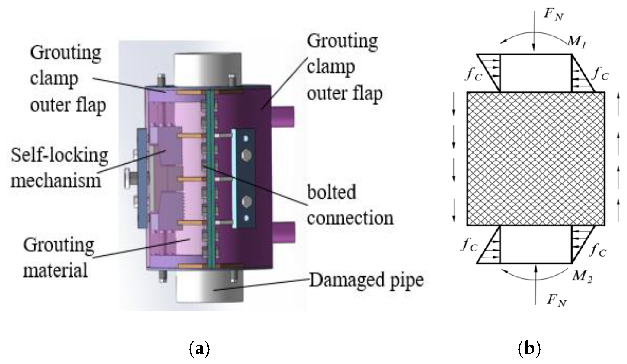
3. Analysis of the Bearing Capacity of a Grouting Clamp Based on a Type of Wedge Gripping

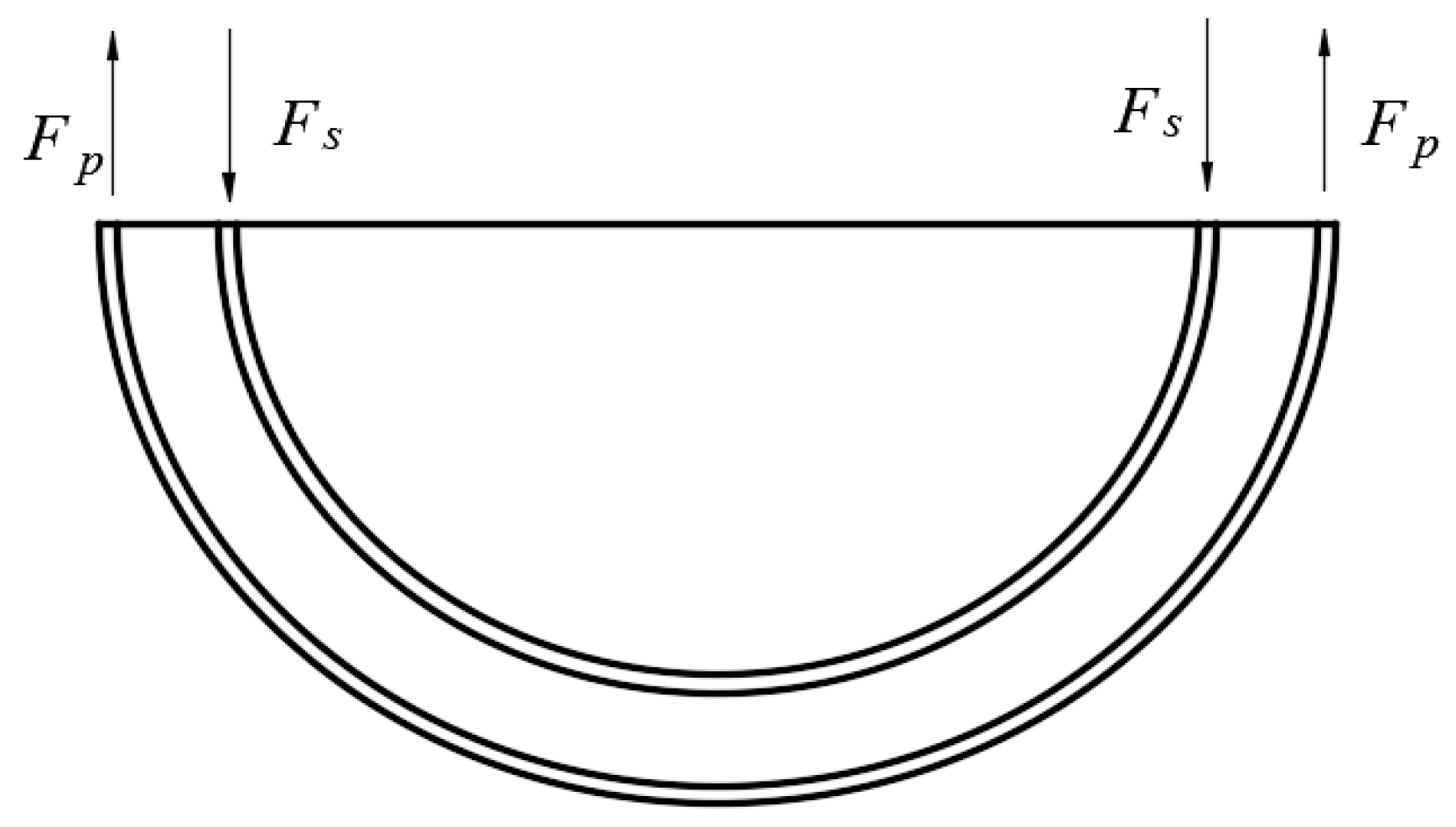
3.1. Analysis of the Axial Bearing Capacity of the Grouting Clamp

In this analysis, a grouting hoop without a shear key was used to reinforce the defective steel pipe. The clamps are connected with high-strength bolts, and the annular space between the light pipe and the outer clamp is filled with cement. The structural section after installation is shown in Figure 8, and the shaded part is the filler cement.
Under the action of axial force, the bearing capacity F1 of the damaged steel pipe with the grouting clamp is composed of two parts: the bearing capacity Fp or Fcp of the defective steel pipe itself and the force F2 between the concrete and the steel pipe.
F 2 = f b a ( 2 π R p L s A d ) + 2 π r g L s f b a
Here, fba is the axial load transfer stress value and has a value of 0.184 MPa, Rp is the outer radius of the defective steel pipe, rg is the inner radius of the grouting clamp, Ls is the length of the clamp, and Ad is the area of the defect in the steel pipe, with A = A1 + Ad.

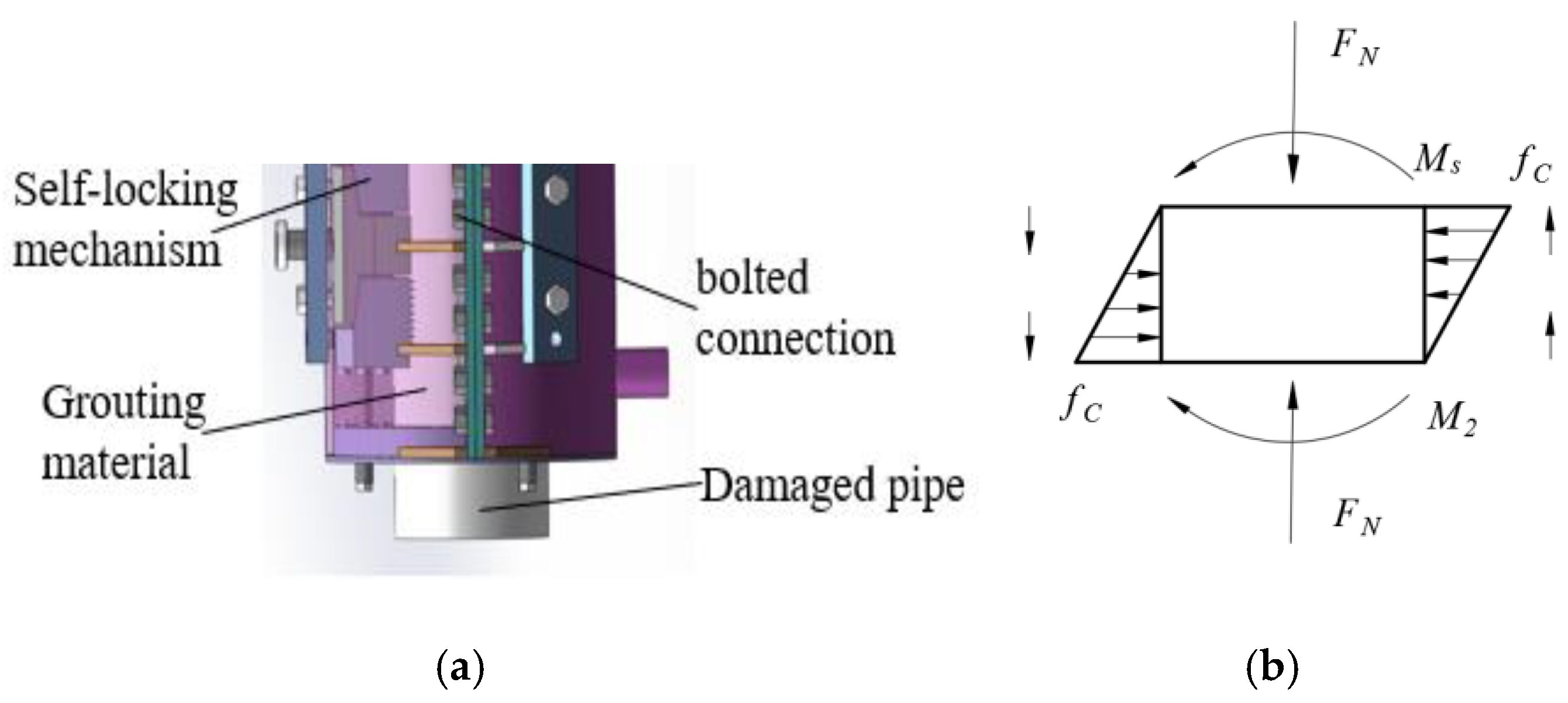
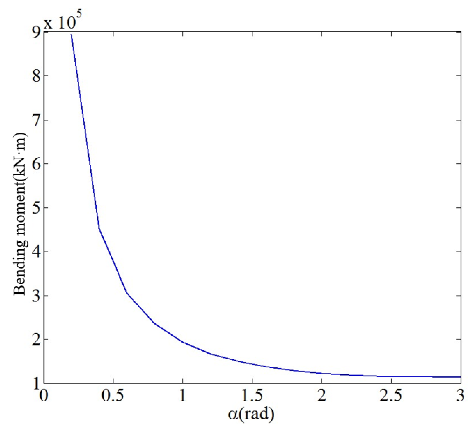
3.2. Analysis of the Moment Bearing Capacity of the Grouting Clamp

After the grouting clamp is installed on the defective steel pipe, its bending capacity Mt consists of three parts: the bending moment capacity of the defective steel pipe itself, the bending moment capacity of the grouting material and the bending moment capacity of the clamp itself. The bending moment capacities of the clamp itself and the undamaged steel pipe can be calculated according to Equation (19):
M 1 = σ max ω z
The value of σmax in the above formula is as follow:
σ max = 0.75 σ y D t 1500 σ y σ max = ( 0.84 1.74 σ y D E t ) σ y 1500 σ y < D t < 3000 σ y σ max = ( 0.72 0.58 σ y D E t ) σ y 3000 σ y < D t < 300 ω Z = π 64 ( D 4 d 4 )
where D is the outer diameter, d is the inner diameter, and σmax is the maximum normal stress.
Because the local structure of the jacket is damaged, its bending capacity and the safety performance of the offshore platform are reduced, so the jacket needs to be strengthened.
Figure 9a is a three-dimensional model diagram of the grouting clamp; Figure 9b is the force analysis diagram of the grouting clamp and shows the strengthened part of the jacket. In Figure 9a, the grouting clamp is composed of the outer flap, self-locking mechanism and bolted connection. In the self-locking mechanism, the wedge clamping mode is adopted to realize unidirectional locking in the bearing capacity direction, so the clamping force can be improved, and the axial bearing capacity can be increased accordingly. The part of the steel pipe that is not covered by the clamp is subject to tangential and normal forces from the external environment. The axial shear force produced by the grouting material is oriented in different directions at different positions. Because the normal force is a certain distance from the centroid, a bending moment is produced.
Compared with the whole steel pipe, the length of the grouting clamp is small, so the bending moment M1 can be regarded as equal to M2. Thus, the bending moment of the section is taken as M2.
According to the analysis of the bottom section of the grouting clamp, which is derived from the bottom of the overall device (corresponding to Figure 10a), the bending moment of the reinforcement area is M2, and the bending moment of the steel pipe is Ms, as shown in Figure 10b.
Thus, M2 = Ms + Mg.
One of the functions of grouting material is to provide a degree of compressive bearing capacity for clamps and steel pipes; thus, there is sufficient compressive bearing capacity in the grouting itself, as shown in Figure 11.
It is assumed that the grouting material is in an elastic state and that the following conditions are met:
{ F g = f c R s 2 t g F p = f c R s 2 t p
When Equation (20) is satisfied, the maximum radial bending moment provided by the grouting material is as follow:
M g = 1 2 f c R p L s 2
According to the bending capacity of the defective steel pipe itself and that of the concrete between the damaged steel pipe and the grouting clamp, the bending moment capacity of the clamp itself can be obtained as follows:
M t = 2 σ y t p r 2 [ 2 sin β sin α ( 1 + cos α ) ] + 1 2 f c R p L s 2 + σ max ω z
It can be seen in Figure 12 that with the increase in α, the bending moment bearing capacity of the defective steel pipe after the grouting clamp is installed decreases. When 0.2 rad < α < 1.5 rad, the bending moment decreases rapidly with α; when 1.5 rad < α, the reduction of the bending moment slows down.

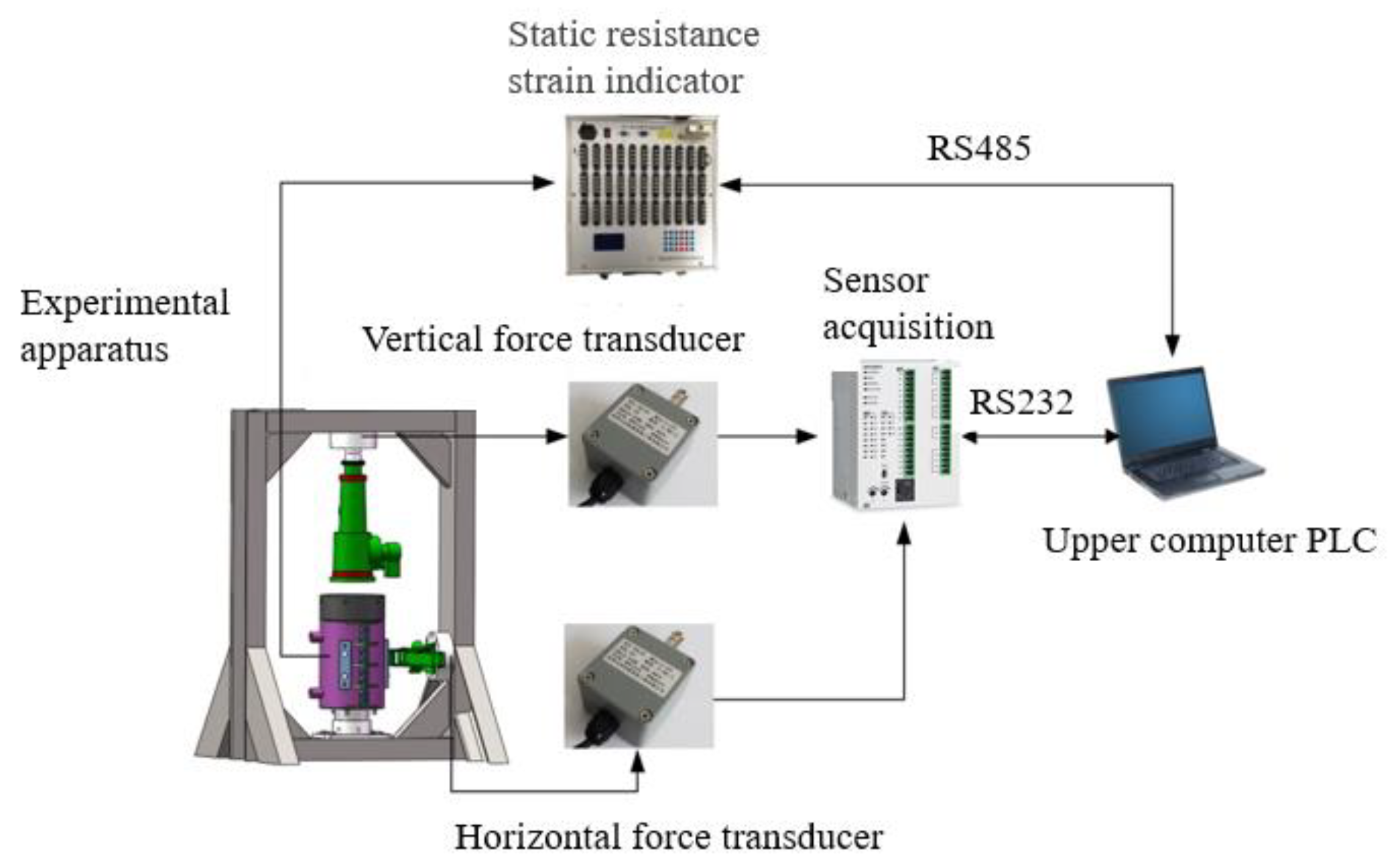
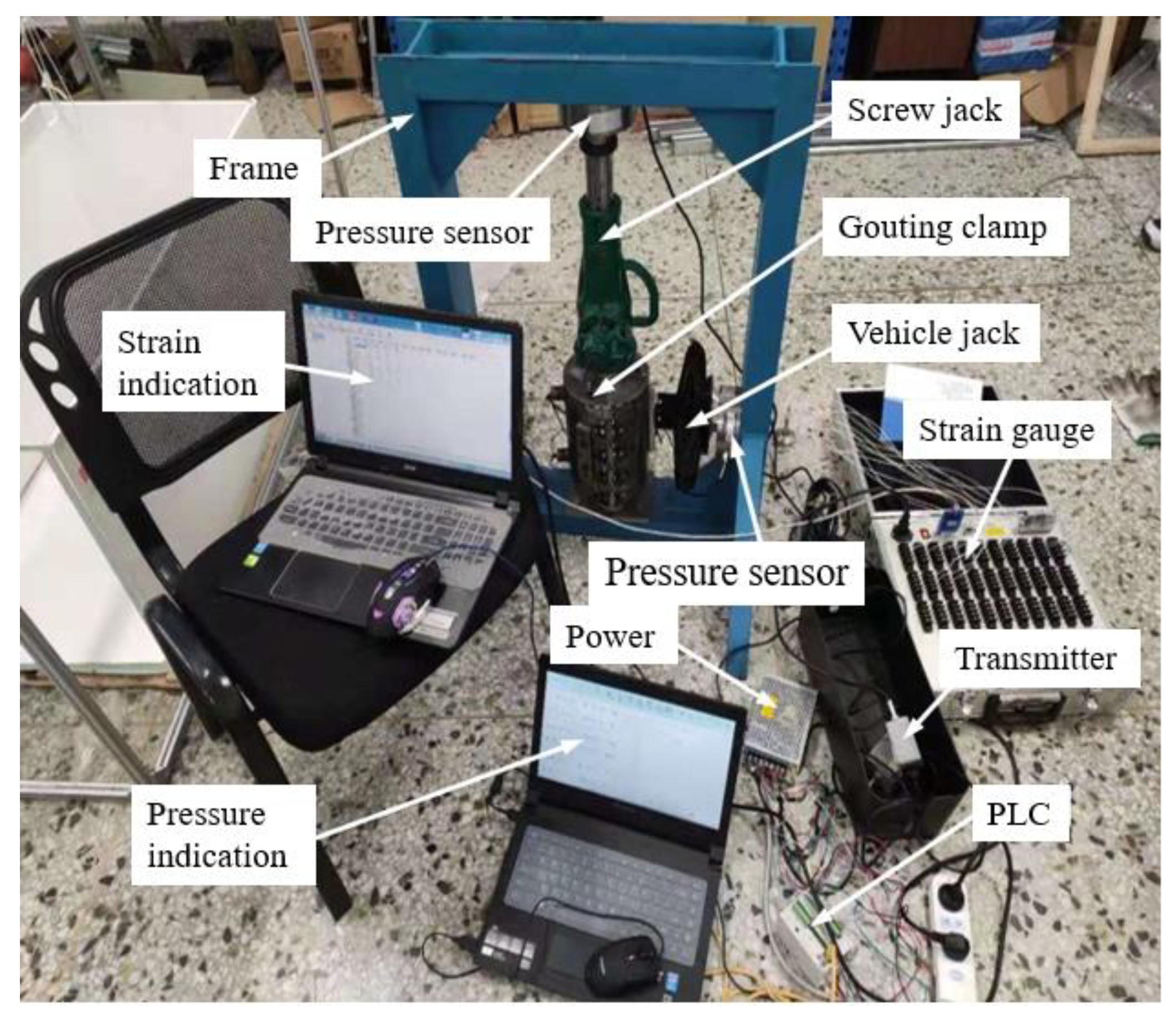
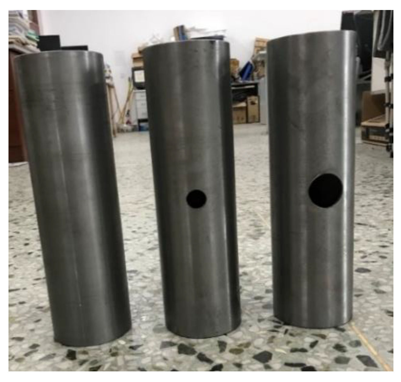
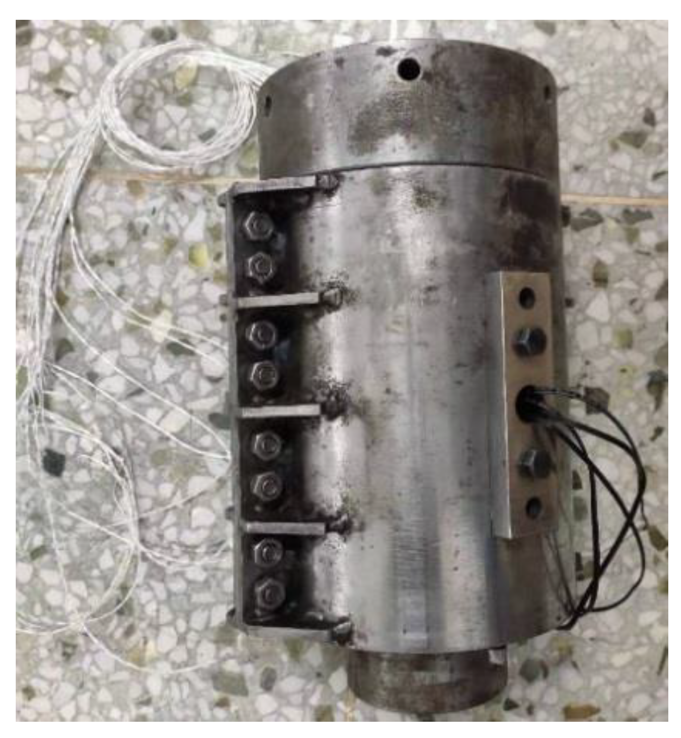
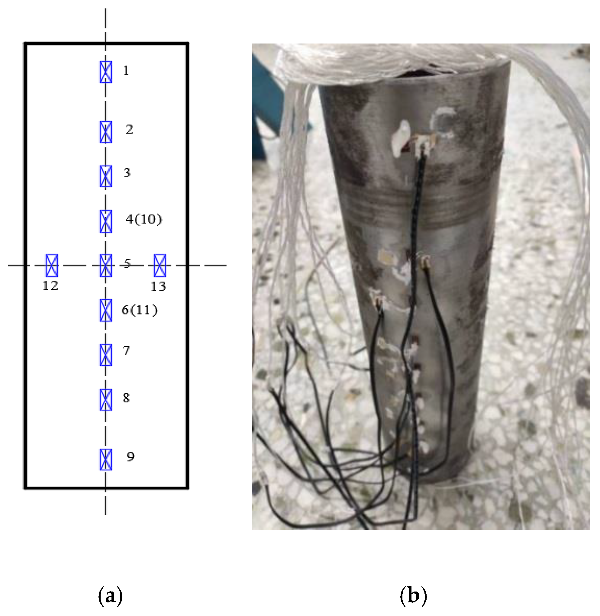
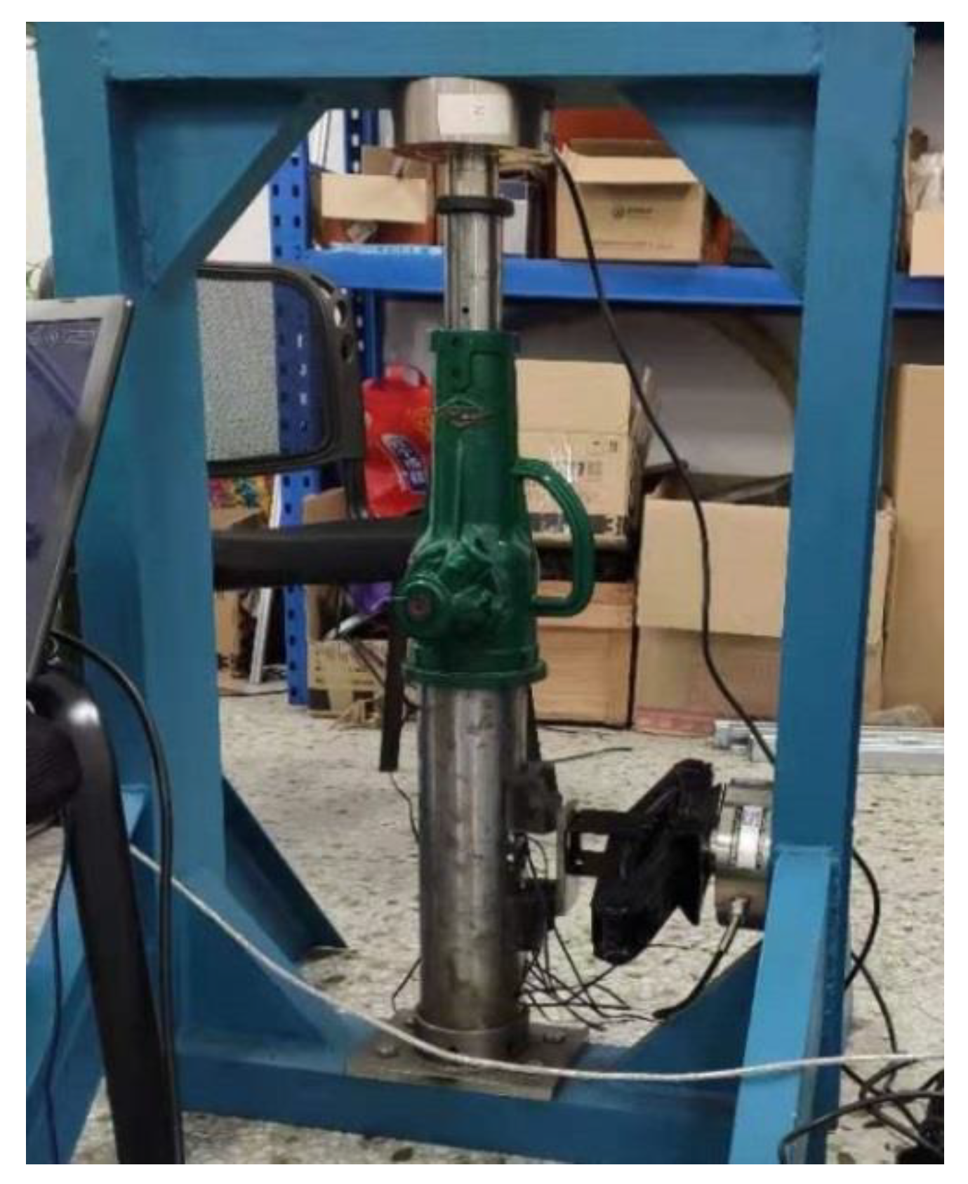
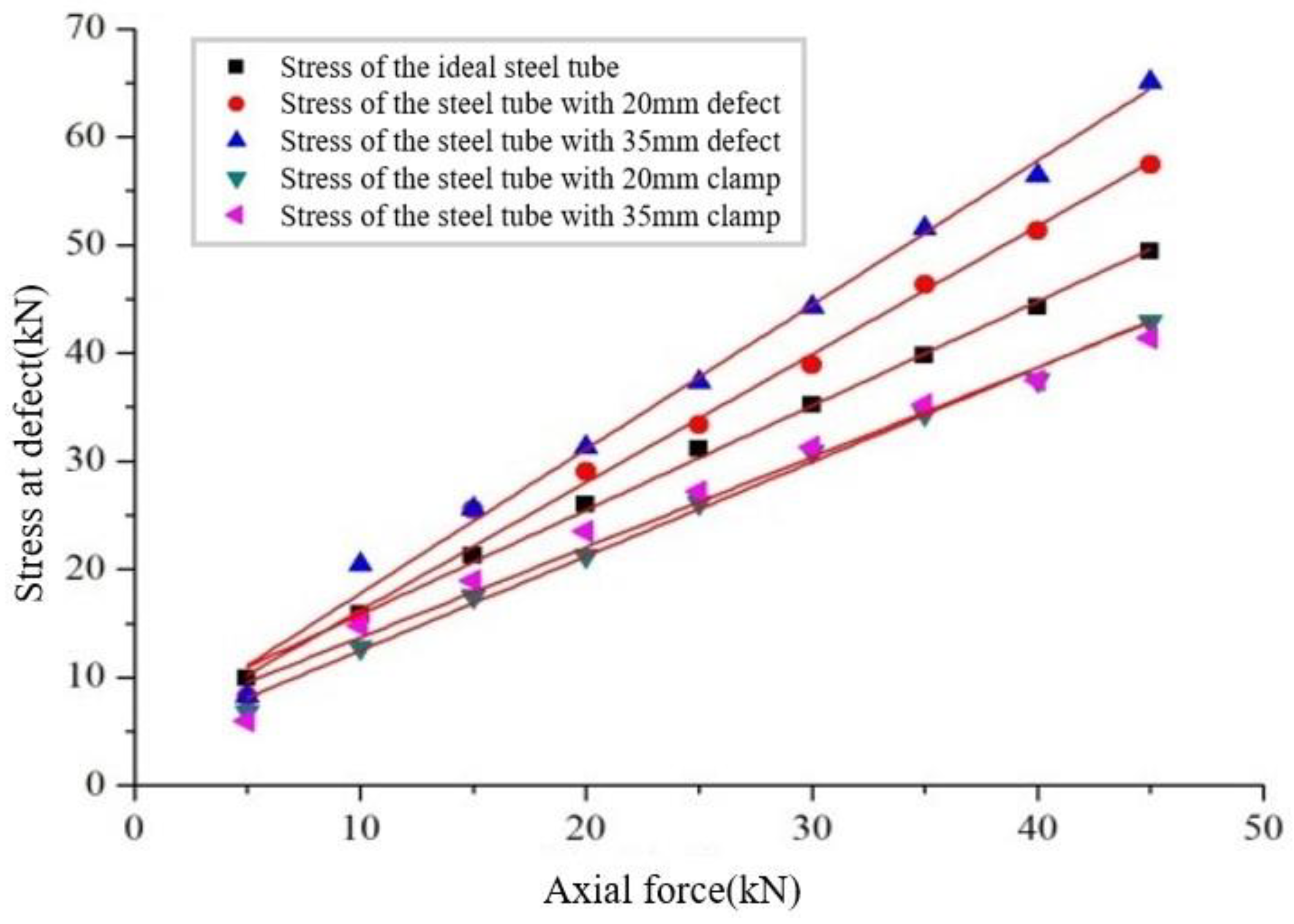
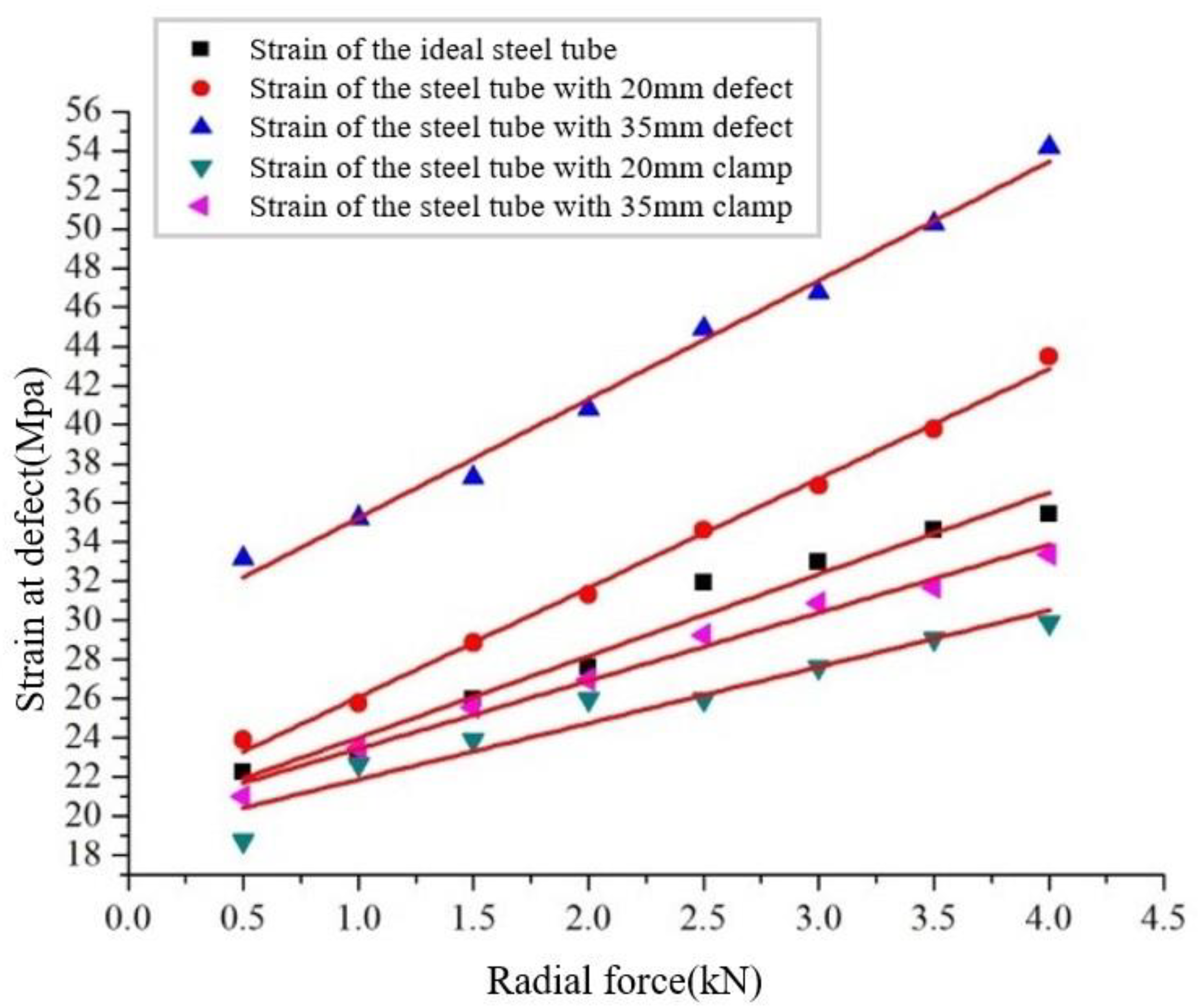
4. Mechanical Experiment Verification of the Grouting Clamp Based on a Type of Wedge Gripping

According to the principle of similarity [22] (geometric similarity, kinematic similarity and dynamic similarity), in engineering applications, the grouting hoop is reduced in equal proportion. The inner diameter of the steel pipe is 84 mm, the outer diameter is 89 mm, and the length is 300 mm. The inner diameter of the mechanical grouting clamp is 159 mm, the outer diameter is 168 mm, and the length is 221 mm. In this experiment, a grouting clamp prototype was used to obtain the data. The composition of the experimental device is shown in Figure 13 and Figure 14. The loading tools in this experiment included a screw jack with a range of 10 t, a vehicle jack, a strain gauge, and a PLC. The screw jack simulates the axial force on the steel pipe and the slippage force on the clamp, and the vehicle jack simulates the radial force on the steel pipe and the clamp. While force is exerted on the steel pipe and clamp, the current signal of the pressure sensor enters the transmitter and is sent to the PLC, which communicates with the computer that ultimately reads and saves the collected data.
The jack force range used in the experiment was 0~10t. A large number of wheels spoke load cells were used to measure and record the force exerted in the horizontal and vertical directions.
The primary goal of the experiment was to determine the deformation size by measuring the strain value so as to establish the reinforcement effect. If the strain value of the defective steel pipe reinforced by the clamp is less than or equal to the strain value of the ideal steel pipe under the same conditions when the load is applied, then the design of the mechanical grouting clamp is successful.
(1) First, axial force was applied to three types of steel pipes (no defect, defect with a diameter of 20 mm and defect with a diameter of 35 mm), and the axial stress distribution was measured while applying increasing force. Then, each strain measurement was obtained from the strain gauge. The strain value of the sheet was determined, and then the car jack was used to apply radial force to the clamp to determine the strain value for the entire pipe.
(2) Then, the reinforcement effect of the clamp was verified. To install the clamp on the defective steel pipe, the screw jack was first used to apply axial force to the clamp, and each strain value was obtained from the strain gauge. Next, the vehicle jack was used to apply radial force to the clamp to obtain the strain value.
(3) The strain values obtained for the defective section were compared with the corresponding values of the non-defective steel pipes to verify the reinforcement performance.
Figure 15 and Figure 16 show the three steel pipes and grouting mechanical clamp.
In the jacket axial compression experiment, the strain values of all measurement points of the ideal steel pipe under axial compression were used as a control group to test the reinforcement effect.
Since the clamp needs to be subsequently loaded to prevent the clamp and its internal metal parts from contacting and crushing the strain gauge, the sticking position of the non-defective steel pipe strain gauge was placed as shown in Figure 17.
The sticking position of the ideal steel pipe strain gauge, as shown in Figure 17, needs to be compared with that of the defective steel pipe strain gauge. For this analysis, the values measured at strain gauges 10, 11, 12 and 13 were used. Because the clamp cannot contact the strain gauge, the gaps between No. 1 and No. 2 and between No. 8 and No. 9 of the strain gauge are large.
The mechanical grouting hoop is subjected not only to axial load but also to current and wave loads. Therefore, the radial loading experiment was carried out for the mechanical grouting hoop. The loading direction was in the defect direction of the steel pipe, and the jack was loaded onto the pipe through two clips.
As shown in Figure 18, in the experiment to verify the influence of radial load on the steel pipe, the pipe was subjected to a certain axial force (ensuring that the pre-applied axial force is the same) to prevent it from deviating when the radial load is applied.
The installation mode and loading scheme of the mechanical grouting clamp are the same as those of the steel pipe, both of which are axial and radial loadings under certain axial pressure. In this experiment, strain gauge No. 13 was selected as the data recording point.
According to the formula σ = e∙ε, the obtained strain values were converted into stress values, and the stress diagrams are depicted in Figure 19 and Figure 20. As shown in Figure 19, as the axial load increases, the maximum stress of the steel pipe with defects increases and is greater than that of the ideal steel pipe, and the larger the defect diameter, the greater the stress. The stress of the steel pipe strengthened by the mechanical grouting clamp is notably less than that of the ideal steel pipe: the stress is reduced by nearly 28% compared with the unreinforced steel pipe. As shown in Figure 20, the change trend of stress under axial and radial loads is the same as that under only the axial load. The stress reduction is about 35%, which is equivalent to a 35% increase in bearing capacity, indicating that the mechanical grouting clamp can effectively reinforce the defect. Although the clamping block can cause damage to the jacket surface, this damage is local plastic deformation, which will not affect the overall strength of the jacket. Furthermore, the effective bearing capacity can be improved as a result of the plastic deformation caused by the block embedded in the jacket surface. Therefore, it is feasible to improve the overall strength of the jacket by local plastic deformation damage.

5. Conclusions

In this study, the bearing capacity of a jacket before and after damage was analyzed, and then the bearing capacity of the damaged jacket strengthened by a mechanical grouting clamp was assessed. These analyses were performed under axial and radial loads, and the results obtained were more representative of the actual working conditions than those under the single-direction load. Then, the bearing capacity of the damaged jacket and ideal jacket before and after hoop reinforcement were compared. It is concluded that the mechanical clamp can increase the bearing capacity by 35%. Finally, a comparison of results obtained from the experiment reveals that the surface defects will have a negative impact on the safety performance of the steel pipe, and the mechanical grouting clamp can effectively strengthen the damaged jacket and enhance the strength.

Author Contributions

The first author, B.Z., conceived the framework of the article and wrote the article; the second author, Q.R.Z., analyzed the bearing capacity of damaged steel pipe pile; the third author, T.W., analyzed the capacity of the grouting clamp; the fourth author, Z.W., was responsible for the mechanical experiment verification of the grouting clamp. All authors have read and agreed to the published version of the manuscript.

Funding

This paper was funded by NSFC (Contract name: Research on ultimate bearing capacity and parametric design for the grouted clamps strengthening the partially damaged structure of jacket pipes, Grant number: 51879063; Contract name: Research on analysis and experiments of gripping and bearing mechanism for large-scale holding and lifting tools on ocean foundation piles, Grant number: 51479043).

Conflicts of Interest

The authors declare no conflict of interest.

References

  1. Ashish, A.; Sudath, C.S.; Ove, M.; Ivar, L. A framework to assess structural integrity of ageing offshore jacket structures for life extension. Mar. Struct. 2017, 562, 37–259. [Google Scholar]
  2. Gong, S.-F.; Jin, W.; Wang, Q.-Z. Repair and assessment of damaged components of offshore fixed platforms. China Ocean Platf. 2001, 16, 37–41. [Google Scholar]
  3. Gong, S.-F.; Shen, X.-W.; Li, F.; Wang, Q.-Z. Research on grouting clamp technology for offshore platforms. Ocean Eng. 2001, 19, 32–37. [Google Scholar]
  4. David, L.; Giovanni, S.; Paul, D. Design of novel drilled-and grouted pile in sand for offshore oil & gas structures. Mar. Struct. 2014, 39, 39–49. [Google Scholar]
  5. Zhao, X.L.; Grundy, P.; Lee, Y.T. Grout sleeve connections under large deformation cyclic loading. In Proceedings of the Twelfth International Society of Offshore and Polar Engineers, ISOPE, Kitakyushu, Japan, 26–31 May 2002; Volume IV, pp. 53–59. [Google Scholar]
  6. Jin, W.-L.; Song, J.; Gong, S.-F.; Bai, B.-R. Bearing capacity and reinforcement analysis of damaged components of offshore platform. Eng. Mech. 2003, 20, 37–42. [Google Scholar]
  7. Zhao, X.L.; Ghojel, J.; Grundy, P.; Han, L.H. Behavior of grouted sleeve connections at elevated temperatures. Thin-Walled Struct. 2006, 447, 751–758. [Google Scholar] [CrossRef]
  8. Jan, D.; Michael, M. Advanced representation of tubular joints in jacket models for offshore wind turbine simulation. Energy Procedia 2013, 35, 234–243. [Google Scholar]
  9. Yang, B.; Shi, X.; Li, H.-J. Pressure measurement method of expansion self-stress grouting clamp. Offshore Eng. 2010, 28, 80–85. [Google Scholar]
  10. Jiang, S.C.; Wang, Z.; Zhao, X.L. Structural Performance of Prestressed Grouted Pile-to-Sleeve Connectionsin. In Proceedings of the Twelfth East Asia-Pacific Conference on Structural Engineering and Construction, Hong Kong, China, 26–28 January 2011; Volume 14. [Google Scholar]
  11. Samarakoon, S.M.S.M.K.; Ratnayake, R.M.C.; Siriwardane, S.A.S.C. Structural integrity control of ageing offshore structures: Repairing and strengthening with grouted connections. In Proceedings of the Asme 32nd International Conference on Ocean, Offshore and Arctic Engineering, Nantes, France, 9–14 June 2013; Volume 3. [Google Scholar]
  12. Djukic, L.P.; Sum, W.S.; Leong, K.H. Development of a fibre reinforced polymer composite clamp for metallic pipeline repair. Mater. Des. 2015, 706, 8–80. [Google Scholar] [CrossRef]
  13. Sum, W.S.; Leong, K.H.; Djukic, L.P. Design, testing and field deployment of a composite clamp for pipeline repairs. Plast. Rubber Compos. 2016, 45, 81–94. [Google Scholar] [CrossRef] [Green Version]
  14. Lee, J.H. Interfacial shear behavior of a high-strength pile to sleeve grouted connection. Eng. Struct. 2017, 1517, 704–723. [Google Scholar] [CrossRef]
  15. Jiao, G.; Zhou, L.; Shi, X.; Fang, K. Load-bearing performance test of large-size model of expansion self-stress grouting clamp. J. Ocean Univ. China 2017, 47, 111–118. [Google Scholar]
  16. Gunnar, S.; Atle, J. Design recommendations for grouted pile sleeve connections. Mar. Struct. 2018, 601, 1–14. [Google Scholar]
  17. Johansen, A.; Solland, G.; Lervik, A.; Strande, M.; Nybo, T. Testing of jacket pile sleeve grouted connections exposed to variable axial loads. Mar. Struct. 2018, 582, 254–277. [Google Scholar] [CrossRef]
  18. Chellappan, N.V.; Nallayarasu, S. Axial and moment carrying capacity of split sleeve grouted connections for repair of tubular member. In Proceedings of the Asme 38th International Conference on Ocean, Offshore and Arctic Engineering, Glasgow, Scotland, 9–14 June 2019; Volume 3. [Google Scholar]
  19. Wu, X.; An, W. Effect of distributed axisymmetric defects on buckling reliability of thin-walled cylindrical shells. J. Harbin Eng. Univ. 2009, 30, 635–638. [Google Scholar]
  20. Yang, X. Experimental study on flexural behavior of corroded reinforced concrete beams. J. Nat. Disasters 2018, 27, 70–78. [Google Scholar]
  21. Yuan, Y.; Jia, F.; Cai, Y. Degradation of mechanical properties of corroded steel bars. Ind. Archit. 2000, 30, 43–46. [Google Scholar]
  22. Wang, X.Q.; Zhang, S.M.; Liao, J.; Huang, Y.S. Research and development on similarity principle of model pile. In Applied Mechanics and Materials; Trans Tech Publications Ltd.: Stafa-Zurich, Switzerland, 2014; Volume 580–583. [Google Scholar]
Figure 1. Shell-shaped tube.
Jmse 08 00973 g001
Figure 2. Shell lateral displacement.
Jmse 08 00973 g002
Figure 3. Jacket piles under axial compression. (a) Steel pipe compression diagram. (b) Simplified bending deformation of the small deflection. (c) the forces balance diagram.
Jmse 08 00973 g003
Figure 4. Equal-effectiveness analysis.
Jmse 08 00973 g004
Figure 5. Calculation diagram of the steel pipe pile.
Jmse 08 00973 g005
Figure 6. The form of local defects.
Jmse 08 00973 g006
Figure 7. Compressive capacity.
Jmse 08 00973 g007
Figure 8. A sectional view of the grouting clamp.
Jmse 08 00973 g008
Figure 9. Grouting clamp reinforcement. (a) Clamp structure diagram. (b) Simplified stresses diagram.
Jmse 08 00973 g009
Figure 10. Analysis diagram of the grouting clamp bottom. (a) Clamp structure of lower part. (b) Simplified stress diagram of lower part.
Jmse 08 00973 g010
Figure 11. Calculation diagram of the steel pipe and clamp.
Jmse 08 00973 g011
Figure 12. Bending moment diagram.
Jmse 08 00973 g012
Figure 13. Schematic diagram of the experimental device.
Jmse 08 00973 g013
Figure 14. Experimental device.
Jmse 08 00973 g014
Figure 15. Steel tubes with three different damage holes.
Jmse 08 00973 g015
Figure 16. Fully assembled clamp for experiments.
Jmse 08 00973 g016
Figure 17. Ideal position of the steel tube strain gauge. (a) Mark the position of steel pipe by sticking stress piece. (b) Pasted the stress piece on the steel pipe.
Jmse 08 00973 g017
Figure 18. Axial loading of the steel pipe.
Jmse 08 00973 g018
Figure 19. Stress at the measuring point of axial load.
Jmse 08 00973 g019
Figure 20. Stress at the measuring point of radial loading.
Jmse 08 00973 g020
Publisher’s Note: MDPI stays neutral with regard to jurisdictional claims in published maps and institutional affiliations.

