1. Introduction
Owing to the limitations of ecological environments and space resources in near-shore areas; offshore aquaculture is becoming growing in the aquaculture industry worldwide. High-density polyethylene (HDPE) net cages are increasingly being used in the aquaculture industry. Generally, an HDPE net cage could be moored in a single or array configuration, which is flexible in industrial applications. However, the volume for aquaculture typically ranges from 10,000 m
3 to 30,000 m
3, not to mention the deformation induced by currents and waves. So far, more than 20 countries and regions around the world have been devoted to aquaculture field. For instance, France and Norway have cooperated to build an aquaculture vessel with 270 m length and the drainage can reach 10
5 t. Spanish companies have designed an aquaculture platform, which can resist to waves of 9 m. Norway, as one of the most developed fisheries countries in the world, has already been leading the world in the field of farming equipment design. Recently, a new type of offshore fish farm, Ocean Farm 1 [
1] (see
Figure 1), which is mainly made up of steel, with a volume of 250,000 m
3 was developed in Norway and built in China. This kind of fish farm may represent the first step toward a new era in offshore aquaculture and address key issues related to sustainable growth in the aquaculture industry. As the aquaculture is marching to the open sea, the power supply of the electrical equipment on the fish farm becomes a weakness of development. The floaters and columns for a fish farm could be ideally used as a wave energy converter platform. The aquaculture platform of sufficient dimensions can support several wind turbines and realize self-power supply of the offshore fish farm. Overall, both the converter platform of wave energy and offshore wind turbine can be combined with this kind of new type of offshore aquaculture facility. Due to its superior performance, the offshore fish farm considered is accepted and widely used all over the world. Hence, fundamental research on the offshore fish farm is very critical, especially in the initial stage.
In open seas, a fish farm is easily subjected to strong currents, severe waves, and storm surges, all of which can cause significant destruction. Therefore, studying the hydrodynamic responses of a net cage is important and urgent. In the past few decades, a considerable amount of research including experimental and numerical studies has been carried out to investigate the hydrodynamic responses of offshore net cages. Fredriksson et al. [
2] analyzed both the motion response and mooring line tension of a net cage in waves and currents. Lader et al. [
3] conducted a series of physical model experiments to study the forces and deformation of a circular net cage with different weights in a uniform flow. Li et al. [
4] adopted a numerical model to analyze the influences of a sinker weight on the deformation and uniform load on the net cage; the results of the numerical simulation agreed well with the experimental data. Moe et al. [
5] calculated the distribution of loads in the net cage owing to current, weights, and gravity based on commercial explicit finite element software. Tsukrov et al. [
6] conducted experimental studies of drag forces on copper alloy net panels and empirical values for normal drag coefficients are proposed for various types of copper netting. Xu et al. [
7] applied a statistical approach to determine the motion and tension transfer functions in irregular waves. Fu et al. [
8] studied an extended three-dimensional hydro-elasticity theory to predict the dynamic response of 5 × 2 floating fish farm collars in waves. Zhao et al. [
9] performed a number of physical model experiments to study the main mooring line tensions and flow velocity magnitudes when the current flowed through multiple net cages. Zhou et al. [
10] presented hydrodynamic characteristics of knotless nylon netting normal to free stream and the effect of inclination angle on drag coefficient were discussed. Kristiansen et al. [
11] investigated the mooring line loads on an aquaculture net cage that was analyzed by model tests and numerical simulations. Huang et al. [
12] investigated the dynamic deformation of the floating collar of a net cage under a combination of waves and currents. Yao et al. [
13] developed a novel hybrid volume approach to model the current loads on a net cage by considering the fluid–structure interaction. Bi et al. [
14] investigated waves propagating through net cages with different levels of biofouling and studied them numerically using a three-dimensional computational fluid dynamics model. In addition, as for the submersible fish cage, Kim et al. [
15] used the computational fluid dynamic software to analyze the flow field characteristics of a submersible abalone aquaculture cage and adopted a finite element model based on Morison equation to study the hydrodynamic responses of the moored containment structure. Shainee et al. [
16,
17] conducted numerical simulations and experimental model tests to examine the submergence characteristics of a self-submersible SPM cage system in both regular and random waves, respectively. Xu et al. [
18] analyzed the hydrodynamic behavior of a self-submersible single-point mooring gravity cage in combined wave–current by numerical simulation.
Although the hydrodynamic responses of the net cage have been studied extensively, studies on new types of offshore fish farms are scarce. Li et al. [
19] conducted a preliminary study on the global responses and mooring line loads of a vessel-shaped offshore fish farm in various waves. However, the effect of waves on the hydrodynamic responses of fish farms is an important research issue. Thus, it is essential to analyze the interaction mechanism between fish farms and waves. Unlike traditional net cages, the semi-submersible offshore fish farm is a new type of aquaculture facility that is unique in the sense that draught of the fish farm can be regulated by pontoons. When the waves and winds are severe, the draught of the fish farm can be increased appropriately to avoid destruction; when the fish farm need to be maintained, it can ascend to the sea surface by controlling the water of the pontoon. In addition, owing to the existence of net, the hydrodynamic response is different from the traditional offshore engineering structure. In this study, a series of laboratory experiments were performed in the wave–current flume to study the hydrodynamic characteristics of a semi-submersible offshore fish farm. The physical model of the fish farm, similar to Ocean Farm 1 [
1], consists of a primary frame, four mooring lines, nets, pontoons, and sinkers. However, as we do not know the detailed information of Ocean Farm 1, the structural parameters of the fish farm in this study are designed according to our own understanding. The objective of this study is to analyze the hydrodynamic responses of this kind of semi-submersible offshore fish farm and provide positive suggestions for its structural optimization. The present research is based purely on scientific interest and has no commercial purpose.
This paper is organized as follows. The laboratory experiments, including the physical model, experimental setup, experimental conditions, and data analysis methods, are presented in
Section 2.
Section 3 presents the experimental results of the mooring line tension and motion response in different draughts. A detailed discussion including an analysis on the wave parameters, draught, and net damping is presented in
Section 4. Finally, the conclusions are presented in
Section 5.
2. Laboratory Experiment
In the open sea, a semi-submersible fish farm can be easily subjected to extreme waves. In order to investigate the hydrodynamic responses of a fish farm in regular waves, a series of physical model experiments were conducted. According to the actual sea conditions, prototype structure size, and experimental conditions, the model size, experimental layout, and wave conditions can be designed. All the laboratory experiments were performed in a wave–current flume at the State Key Laboratory of Coastal and Offshore Engineering, Dalian University of Technology, Dalian, China.
2.1. Physical Model
The physical model (see
Figure 2) consists of the primary frame, net, weight, and mooring systems. The draught of the fish farm can be adjusted by changing the volume of ballast water in the pontoon to determine the working station. In the experiment, it is difficult to completely meet the same similarity law for each part of fish farm, so in order to reduce the influence of the scale effect on the structure, especially the simulation accuracy of the net, the study adopts different similar scales for the net and frame structure. The full scale can be designed by the gravity similarity. The frame and net system adopted two geometric scales, which were 1:120 and 3:40, respectively. More details about the similarity law and the calculation of full-scale values can be found in previous research [
20,
21].
2.1.1. Frame System
The frame system is the primary structure that bears the environment load and constitutes the fish living space with the net. The frame system of the fish-farm model is made up of plexiglass and includes column, arc pipe, brace, and pontoon (see
Figure 3). In accordance with the dimensions of the experimental facilities and the tested wave conditions, the diameter of the fish-farm model is set to 1 m. The detailed parameters of the fish farm in this study are presented in
Table 1. The prototype values of the fish farm are also shown with a geometric similarity scale of 1:120, which is roughly similar to the dimensions of Ocean Farm 1 [
1]. The deformation of the primary frame of fish farm is small and has a negligible effect on the hydrodynamic responses of the fish farm; therefore, the elastic similarities need not be considered.
2.1.2. Net System
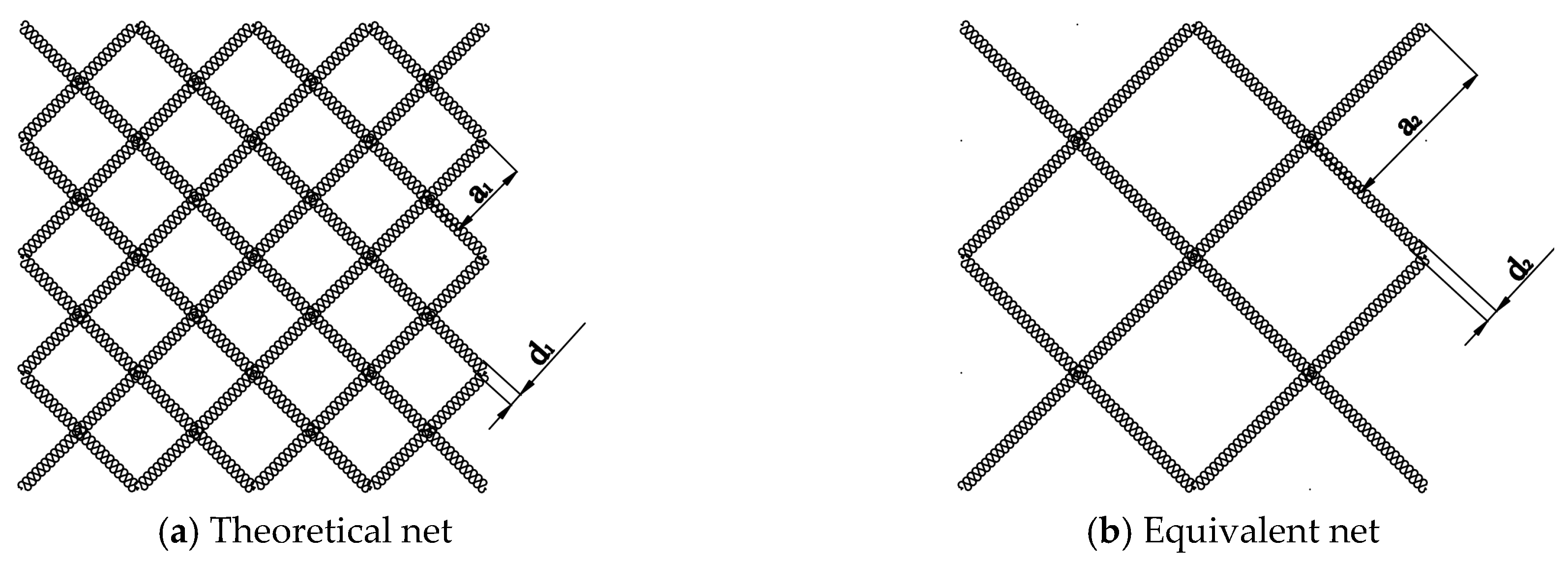
The net system was designed with three parameters: The overall size, mesh size, and net diameter. To avoid an extremely small net diameter with the model scale of 1:120 such that the model net can hardly be attained, the experimental model primarily considered the drag force to guarantee that the force on the theoretical net is equal to that on the model net (see
Figure 4). In the traditional net cage, the whole net system is flexible structure and exhibits a large deformation in regular waves. However, the effect on the deformation of net combined with the fish farm is slight. In the experiment, the net system is designed based on our previous research [
20]. The geometric similarity of the net is as follows:
where
and
are prototype mesh size and prototype net diameter, respectively;
and
are the mesh size and net diameter of the model, respectively.
The prototype mesh size and net diameter are 5 cm and 3.75 mm, respectively. Therefore, it can be calculated that the ratio of the mesh size to the net diameter should be 40/3, such that the drag force on the theoretical net is the same as that on the equivalent experimental net. Through preliminary calculations, the mesh size is 8 mm and the net diameter is 0.6 mm in the experiment.
To guarantee the gravity similarity, the net system is designed based on a previous research study [
20]. The gravity similarity of the net is as follows:
where
is the corrected weight of the net;
is the small scale of the net that can be calculated by
;
is the geometric scale;
is the prototype net diameter;
is the model net diameter;
is the net material density;
is the water density;
is the prototype mesh size;
is the solidity ratio of the net;
is the hanging ratio area of the model net;
and
are 0.707 and 0.707, respectively.
Some differences in weight exist between the theoretical net and the equivalent net. To guarantee the weight similarity, it is calculated that the weight of the equivalent net should be increased by 6.7 g, which can be adjusted by the weight system. Owing to the weak elasticity and stiffness of the polyethylene net, the elasticity similarity of the net will not be considered.
2.1.3. Weight System
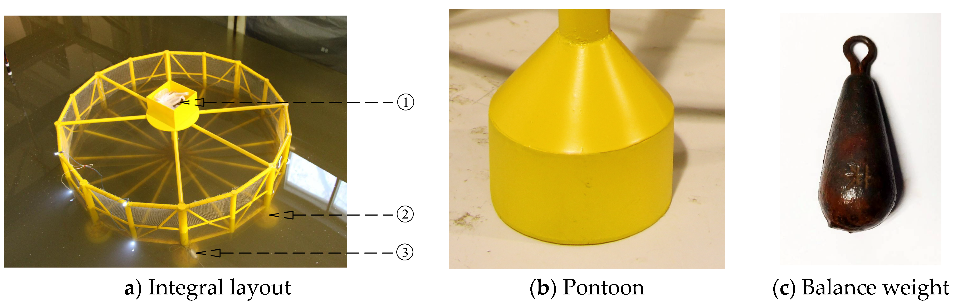
To overhaul and operate the fish farm, the draught of the fish farm can be controlled by a weight system (see
Figure 5a) to attain a specified state in practical applications. In the experiment, combining the actual state with experimental conditions, the draught can be adjusted by injecting the water into the pontoon (see
Figure 5b) and by a sinker (see
Figure 5c). In addition, three draughts exist, including those of 7 cm, 28 cm, and 36 cm, representing the maintenance condition and two working conditions of the fish farm, respectively. Meanwhile, the maintenance condition can be reached depending on its own weight; no additional weight is required. However, the working state 1 can be obtained by hanging weights at the bottom of column, injecting water into the pontoon and adding sand to the top box, and the working state 2 needs to continue to add sand into the box to achieving the draught of 36 cm. The detailed conditions can be presented in
Table 2.
2.1.4. Mooring System
The mooring system is an important part of the fish farm and is crucial for the fish farm to operate steadily in the sea. In the experiment, a four-point anchor form was adopted in the fish farm and the initial tension could be loaded in the mooring line. In the practical application, the wave loads on the mooring line are smaller than those on the fish farm; therefore, the elastic similarity was considered primarily in the experiment such that the model mooring line is similar to that of the prototype and to reduce test errors. The elastic part of the anchor is modeled by the spring, and the anchor rope can be fixed by lead blocks at the bottom. The relationship between the force and the calculated value of elongation of the mooring line can be calculated by Formula (4). The results can be listed in the
Table 3.
where
is the model cable tension;
is the elastic coefficient of prototype cable, which is
;
is the diameter of prototype cable, which is 120 mm;
is the elongation rate of prototype cable;
is the coefficient, which is 1.5;
is the geometric scale.
As listed in
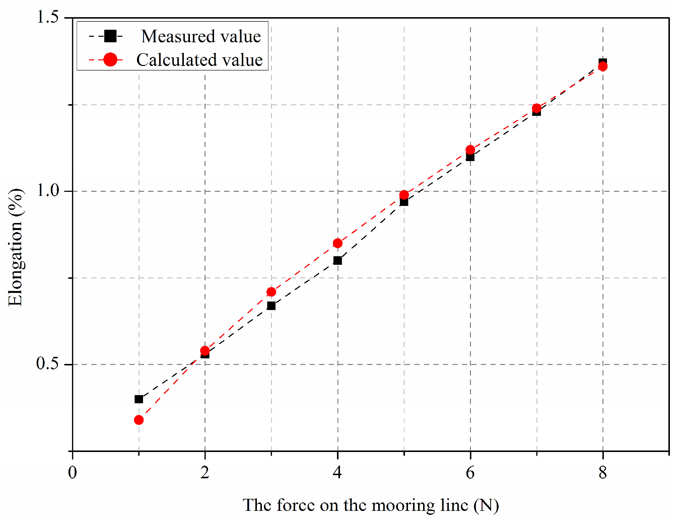
Table 3, the relationship between the force and the calculated value of elongation of the mooring line is close to linear. Therefore, the elasticity of the mooring line can be simulated by the spring in the experiment. To obtain a suitable spring, a variety of springs were tested (see
Table 4). It can be concluded that the mooring line of the model can be simulated by a polyethylene rope and spring. The mooring line was 3.0 m long in the physical model experiment.
The comparison between the calculated elongation of the mooring line and the measured values is shown in
Figure 6. It is indicated that the error is small; therefore, the method of simplifying the mooring line is feasible.
2.2. Experimental Setup
The wave–current flume is 69 m long, 2 m wide, and 1.8 m deep, and the water depth was 1 m during the experiments. In addition, the flume is equipped with a servo motor-driven, piston-type wave-maker capable of producing regular and irregular waves. At the end of the flume, wave absorbers are installed to mitigate the wave reflection. Both sides of the flume at the working section are smooth glass to reduce viscous dissipation owing to the boundaries. In this flume, both waves and currents can be generated. However, only regular waves were generated in this physical model experiment.
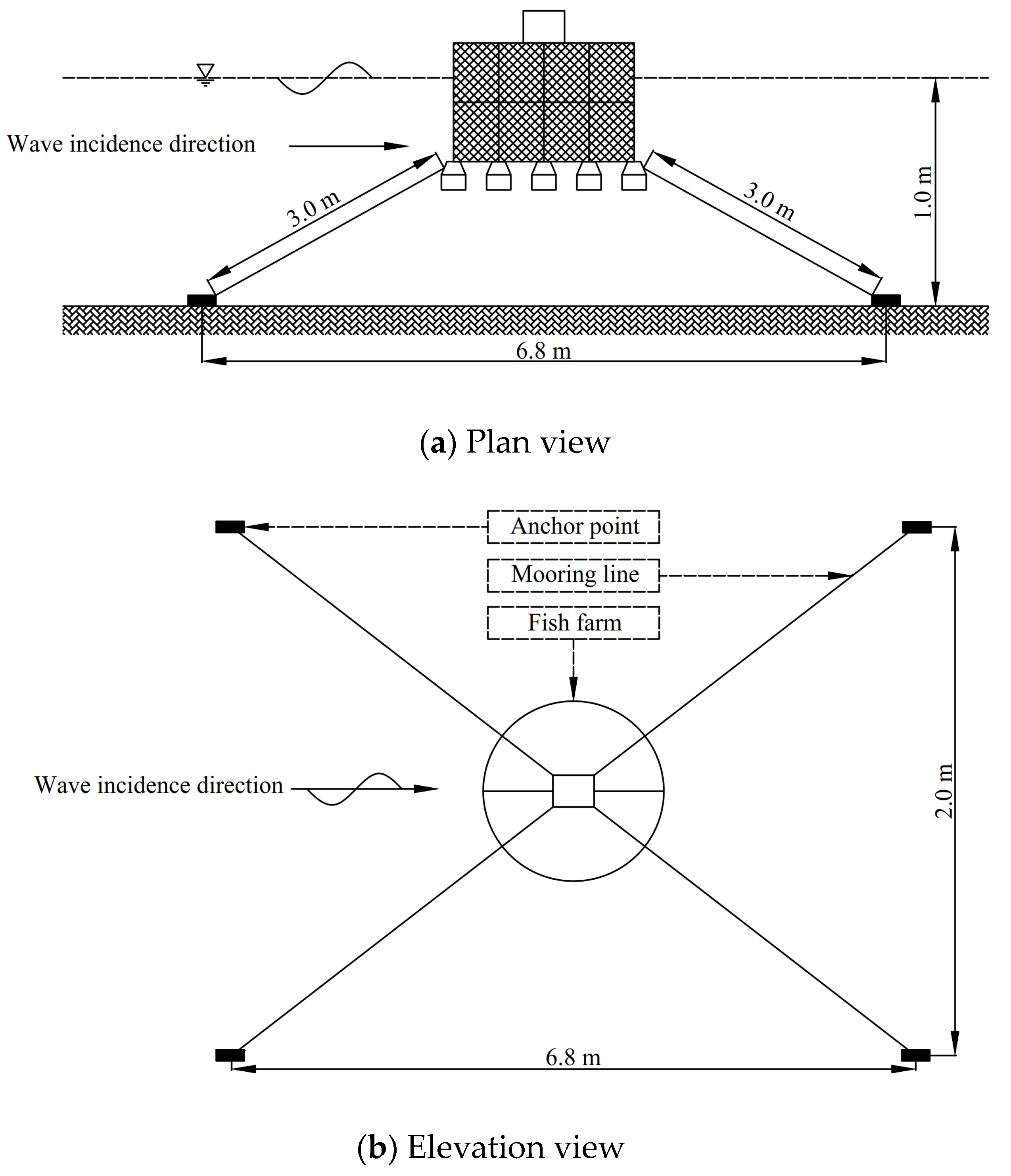
Figure 7 shows a sketch of the experimental setup. The fish farm model was moored by four mooring lines in its equilibrium position. Each mooring line primarily comprises one 2.9 m polyethylene rope whose diameter is 1.0 mm and one 0.1 m stainless spring. The linear density of the rope is 0.003 kg/m and the mass of the spring is 0.01 kg. To measure the forces acting on the mooring lines, four load cells were connected to the windward and leeward mooring lines.
To obtain the motion response, a charge-coupled device (CCD) camera was used to record the motion trajectory of the diodes that can be fixed on the fish farm, and the motion responses of the fish farm can be calculated by a self-developed software DUT-FlexSim. The motion response can be collected by the CCD high-speed acquisition camera that is arranged in the observation area of the flume (see
Figure 8). To guarantee the accuracy of data acquisition of the motion response, the surrounding light should be maintained dark. Four light-emitting diode (LED) bulbs are arranged at the top and bottom of the fish farm as tracing points (see
Figure 9). The tracing points along the
x-axis direction are called the front point, and the tracing points on the back side are called the back point.
2.3. Experimental Conditions
In the physical model experiment, the hydrodynamic response of fish farm can be measured in regular waves. According to the model scale, the experimental water depth can be designed to be 1.0 m and its corresponding prototype water depth is 120 m. The mooring line tension and motion response can be measured by the load cells and CCD, respectively. To guarantee the accuracy of data collection, the measurements were performed thrice, and the sampling rate was 0.02 s. Three draughts exist, including those of 7 cm, 28 cm, and 36 cm. In addition, the regular waves were designed as per the specifications in
Table 5.
2.4. Data Analysis Method
In the experiment, the water surface elevations were recorded by capacitance-type wave gauges arranged along the center line of the wave flume. The absolute accuracy of these wave gauges is approximately ±1 mm. Before initiating any measurements, the wave gauges were examined for soundness, cleaned if necessary, and subsequently calibrated. In addition, a computer control system developed by the Beijing Hydraulic Research Institute was used for collecting the data of free surface elevations with multiple channels. To collect accurate data, the time series of wave elevation at each measurement point was recorded with a sampling rate of 50 Hz and a stable data over a period of 10 s was chosen for data analysis; subsequently, the wave height at a measurement point was the average value of the corresponding time series.
Water-resistant load cells with a capacity of 10 N were used to measure the forces on the mooring lines, and the specified accuracy of the load cell was 0.1 N. Each measurement was performed thrice to diminish the impact of random and bias errors. Data sampling was conducted over a period of 20 s and the final experimental value was the average value of the three measurements.
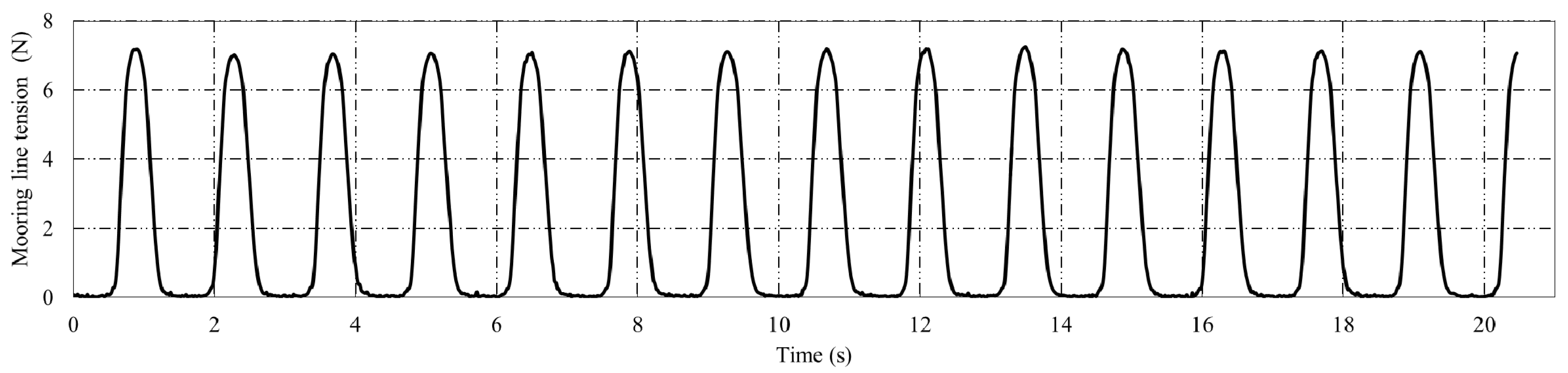
Figure 10 is the time series of mooring lines tensions when the wave height is 10 cm and the wave period is 1.4 s in a draught of 36 cm. The pretension of mooring line was measured before each group of tests began, and then the total force on the mooring line can be obtained by the load cells. Therefore, the mooring line tension in pure waves can be calculated as follows.
where
is the average value of maximum mooring line tensions in pure waves;
is the average value of maximum mooring line tensions which can be measured by water-resistant load cells;
is the pre-tension of mooring line. The windward and leeward pre-tension are 1.91 N and 1.87 N, respectively.
4. Discussion
The semi-submersible offshore fish farm is a new type of aquaculture facilities unlike the traditional net cage. The new fish farm has the advantages including the resistance to severe waves, small deformation, and convenient towing. To analyze the hydrodynamic response of the fish farm in detail, the wave parameters, draughts, and net damping should be considered in the research.
4.1. Effects of Wave Parameters
In the open sea, the fish farm is easily subjected to the wave action; therefore, the wave heights and wave periods are two important factors affecting the hydrodynamic response. As the wave heights increase, the mooring line tension and motion response exhibit an upward trend. This is because the area that can be loaded by waves gradually turn to increase with the wave heights increasing so that the motion amplitude will become larger and the mooring line will be strained, which will produce a larger mooring line tension. In addition, the results above indicate that when the draught is 7 cm, no obvious correlation exists among the mooring line tension, motion response, and wave periods. This is due to the complex pontoon that can be submerged. The surface area of the pontoon is not linearly proportional to the height along the vertical of the water surface; further, a gradual change exists in the connection between the pontoon and the column.
Taking the draught of 28 cm as an example, when the period changes from 1.0 s to 1.2 s and 1.4 s, the increment of windward force on the mooring line is from 80% to 7.6% in the wave height of 6 cm and the increment of leeward force on the mooring line is from 141% to 49% in the wave height of 6 cm. It is apparent that the trend of growth is gradually becoming slower with the increasing of wave periods. Meanwhile, the windward and leeward peak values can reach 3.37 N and 1.71 N, respectively, whose prototype values are 5823.36 kN and 2021.76 kN, respectively. In addition, when the wave height is 10 cm, the fluctuation range of the heave value ranges from 191.13% to 30.17% at T = 1.0 s–1.4 s; the fluctuation range of the surge value ranges from 96.15% to 16.80% at T = 1.0 s–1.4 s; the fluctuation range of the pitch value ranges from 54.48% to 10.79% at T = 1.0 s–1.4 s. It can be concluded that the increase rate of the motion response decelerates with increasing wave period. However, the whole effect on the fluctuation value of the fish farm became more evident with wave period increasing; further, when the period increases to a certain extent the surge value of the fish farm tends to be stable.
The comparison of the windward and leeward forces of the mooring line tension can be represented in
Figure 16, where the wave height and wave period are 6.0 cm and 1.4 s, respectively. It can be concluded that the mooring line tension in the line 2 is less than that in line 1. Using the draught of 28 cm as an example, it can be calculated that the maximum force is attenuated by 61.7% and 70.8% from the windward side to the leeward side at
H = 6 cm and
H = 10 cm, respectively. It can be explained that the wave-ward lines are more loaded due to the non-linearity and drift forces when the wave reaches the fish farm. On the contrary, less external force exists on the leeward mooring line than that in the windward. Therefore, the wave loads on the fish farm acts primarily on the windward mooring line and the leeward force is relatively smaller.
4.2. Effects of Draught
To overhaul and run the fish farm, different draughts can be adjusted by the weight system. With the change in draught, the force on the mooring line and the motion response will present different variation tendencies. It can be observed from
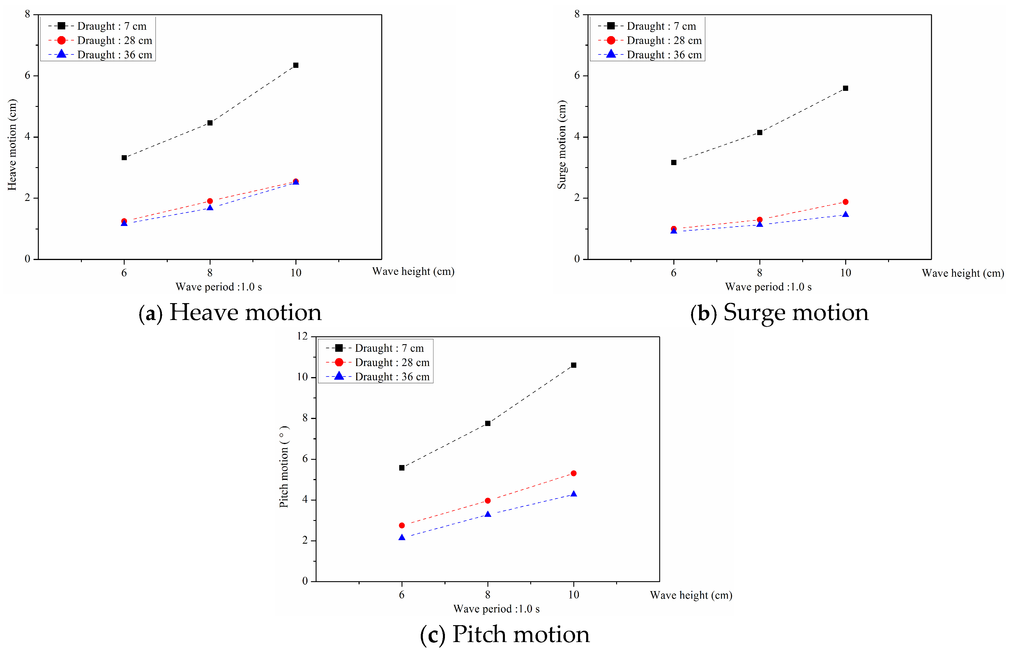
Figure 17 that as the draught continues to increase, the windward force on the mooring line decreases. This is a desirable phenomenon that will provide a technical method for the security of the fish farm in severe waves. In addition, it can be calculated that the maximum reduction reaches 49.8% when the wave height is 10 cm. Meanwhile, it is apparent from
Figure 18 that the motion amplitude exhibits a downward trend with increasing draught, and that the maximum attenuation including the heave, surge, and pitch motion can reach 75.6%, 73.9%, and 59.8%, respectively, when the wave height is 10 cm. This phenomenon can arise because the sloping bottom and the pontoons around the bottom contribute to the vast majority of volume of the fish farm. Therefore, a considerable wave force is produced by the interaction between the waves and structures. With the draught increases, the primary volume of the fish farm is submerged to a certain water depth and interacts with the lower velocity of the water particles. Meanwhile, the primary parts that interact with the waves are the columns in the circumference and the net chamber around the free surface that experience significantly weaker external forces. Thus, the wave force acting on the fish farm decreases gradually. In practical implication, the draught of the fish farm can be increased appropriately to maintain the stability of the fish farm and to avoid severe wave loads from acting on the fish farm.
4.3. Effects of Net Damping
From comparing the new semi-submersible offshore fish farm and a traditional semi-submersible offshore platform, it is apparent that the primary difference is whether a net exists. The existence of net will pose certain effects on the mooring line tension and motion response of the fish farm.
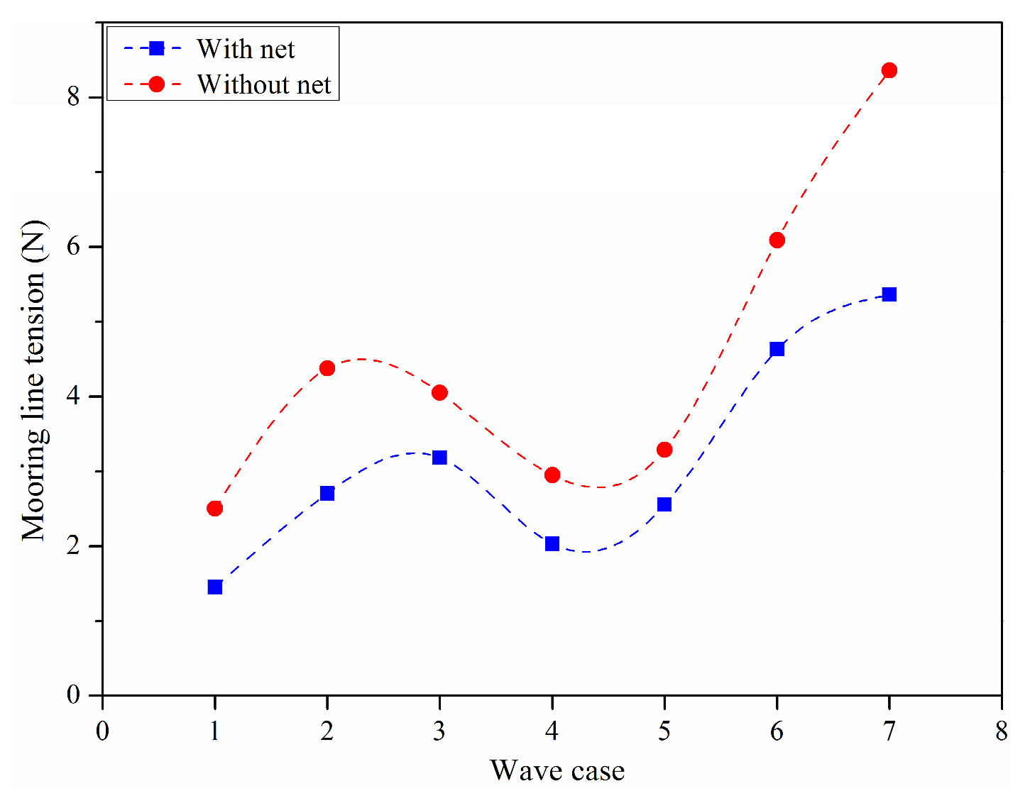
Figure 19 shows the comparison of the windward mooring line tension with or without net in the draught of 36 cm. It can be observed that the mooring line tension in different regular wave decreases owing to the existence of nets, and the maximum reduction can reach 42%. The phenomenon can be explained by the shielding effect and damping effect of the net [
22,
23]. When the wave passes the net, the wave energy will be attenuated, and the wave height reduces significantly, such that the wave loads on the leeward fish farm exhibit a downward trend. Meanwhile, the fish farm will produce a relative motion along the direction of the wave propagation so that the fluid will exhibit a greater damp effect on the net and produce a reverse force. Compared with the no-net state, the horizontal motion amplitude will be restrained to a certain extent (see
Figure 20) and the mooring line tension decreases. Overall, it can be concluded that the mooring line tension will exhibit a downward trend for the fish farm with a net compared with no net.
As for different wave conditions, the change trend of surge motion of the fish farm is the same as that of the mooring line tension. The surge motion will reduce for the fish farm without net. This is because the fluid damping will produce an important impact on the net. Overall, the surge motion of the fish farm with net is less than that without net, and the maximum difference can reach 51%. In addition, the heave motion and pitch motion of the fish farm with net are larger than that without net, and the maximum difference can reach 19% and 22%, respectively. It can be concluded from
Figure 20 that the existence of net affects the pitch motion less but affects the surge motion more.
In the paper, the hydrodynamic response was studied and analyzed in the pure waves. Due to the existence of waves, the motion response of the fish farm will be significantly affected. However, in the actual sea conditions, waves and currents always exist at the same time and have an interaction with each other. The existence of water flow is equivalent to adding an external load on the fish farm, which will have a greater impact on the anchor rope force. Therefore, in the next work, the hydrodynamic characteristics of the fish farm under the combined action of waves and currents will be considered, which will provide suitable suggestions for the application of practical projects.
5. Conclusions
In the present study, the hydrodynamic responses of a semi-submersible offshore fish farm in regular waves were investigated at various draughts using physical model experiments. The mooring line tension and the motion response of the fish farm were analyzed. The conclusions are summarized as follows:
(1) The mooring line tension and motion response were closely proportional to the wave period and wave height. Nevertheless, when the draught was 7 cm, no obvious correlation existed between the hydrodynamic response and wave periods. In addition, the force on the windward mooring line was higher than that on the leeward; further, the upstream anchor lines endured most of the external loads on the fish farm. Therefore, the upstream anchor lines should be optimized and materials with better mechanical properties should be chosen in the actual operation.
(2) As the draught increased, the mooring line tension and motion response exhibited a slight downward trend. Although the area of interaction between the fluid and structure increased, the range of wave action was near the sea surface; subsequently, the effect became weaker gradually with increased draught. In addition, owing to the damping effect of fluid, the motion of the fish farm was limited and the force on the mooring line exhibited a slight downward trend. The experimental results provided a good method to avoid severe waves.
(3) The existence of net affected the hydrodynamic characteristics of the fish farm significantly. Compared with the fish farm without net, the mooring line tension exhibited an obvious increase and the reduction in the peak value could reach 42%. Because of the shielding effect and damping effect of the net, the surge motion of the fish farm exhibited a maximum attenuation of approximately 51%. However, the heave motion and pitch motion increased to some extent. It can be concluded that the net affected the surge degree the most but affected the heave and pitch degrees the least.
(4) Pure waves have a great influence on the motion response of fish farm and is a critical factor affecting the stability of fish farm, so it is important to design a suitable parameter to decrease or avoid the large motion of the fish farm. However, in actual sea conditions, the presence of water flow will increase the anchor rope force and affect the waves. Therefore, in the following work, the hydrodynamic response of the fish farm under the waves and currents will be studied to provide some experimental guidance for the practical engineering.


