
Frequency Shift Keying-Based Long-Range Underwater Communication for Consecutive Channel Estimation and Compensation Using Chirp Waveform Symbol Signals


Abstract
:1. Introduction
2. System Model
3. Proposed Method
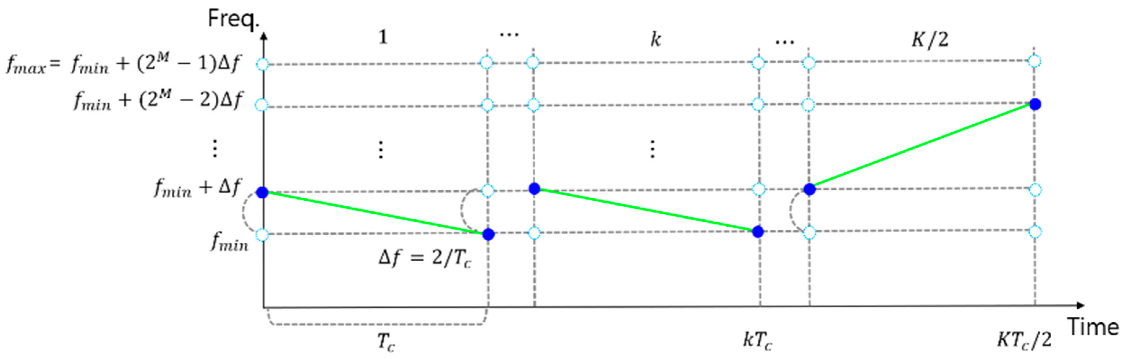
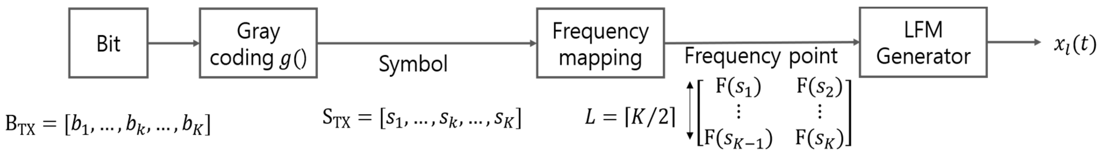
3.1. Modulation
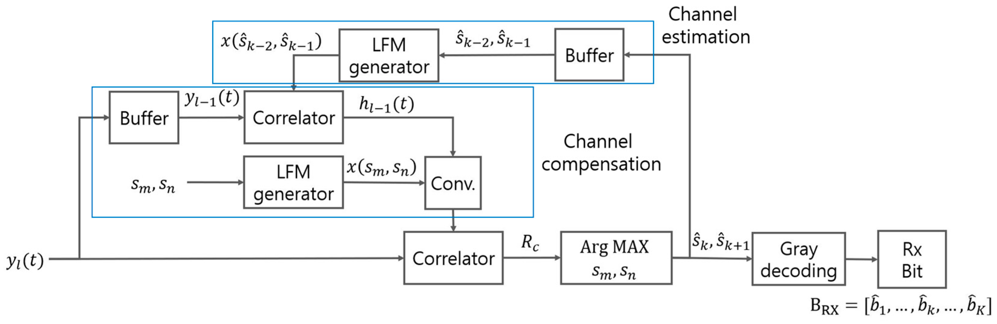
3.2. Demodulation
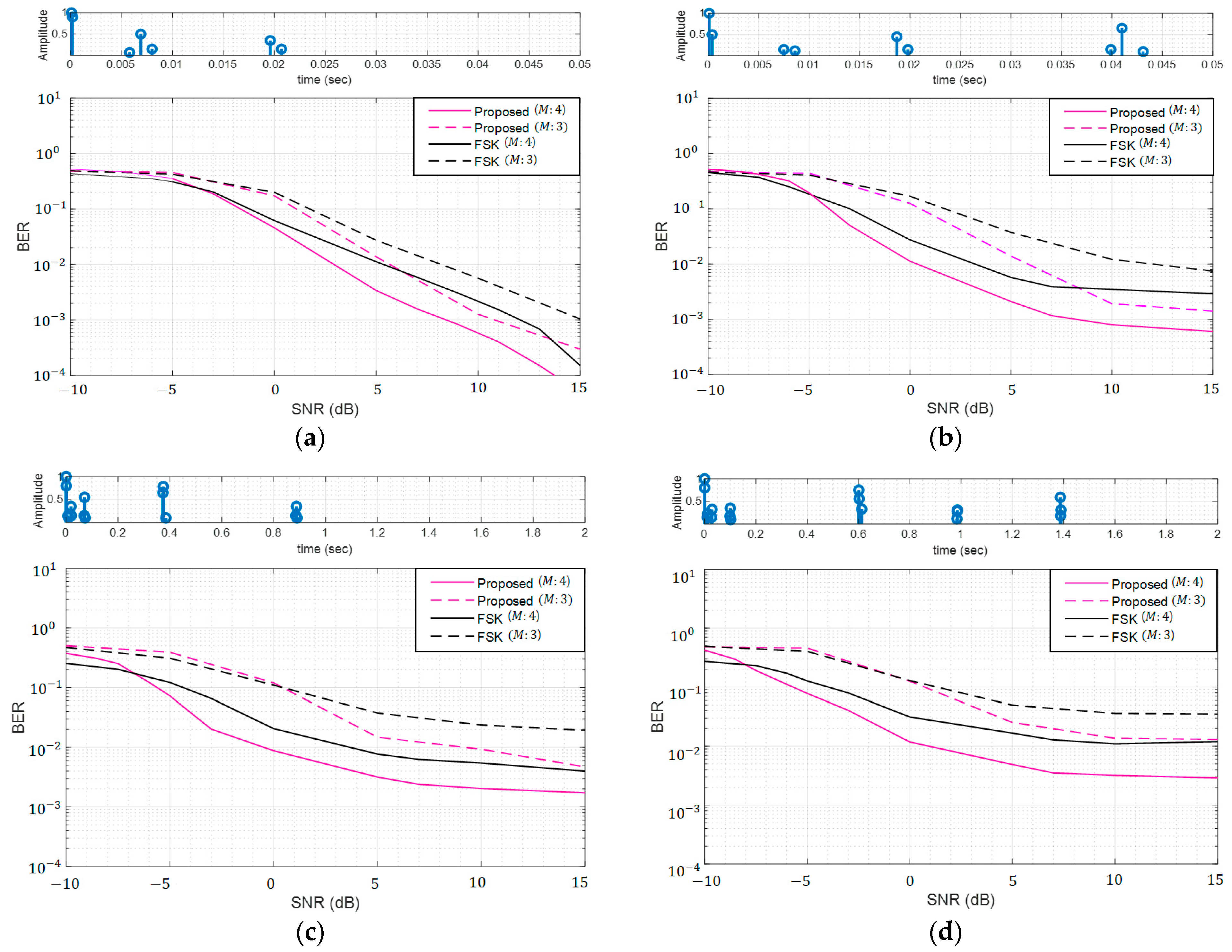
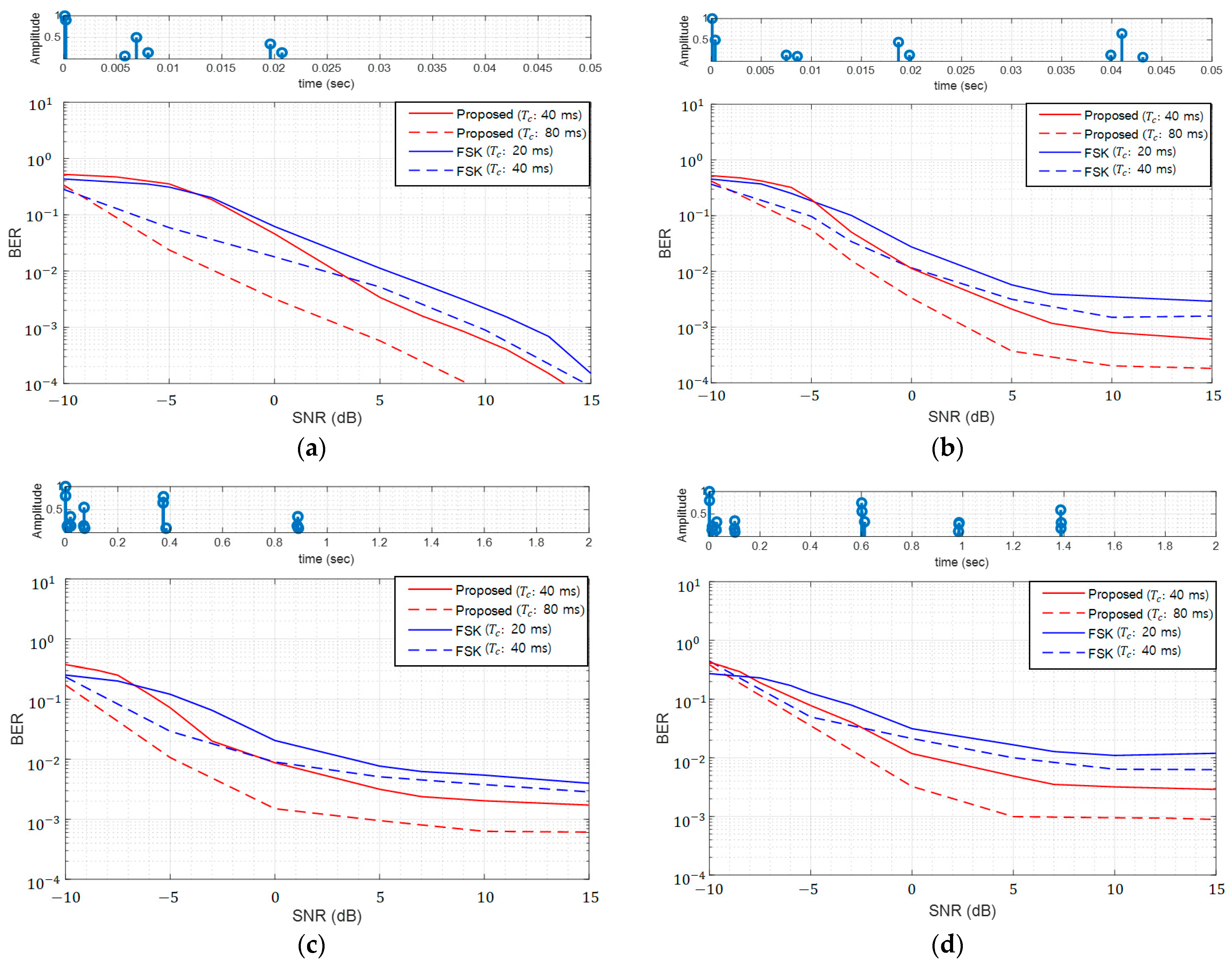
4. Simulation
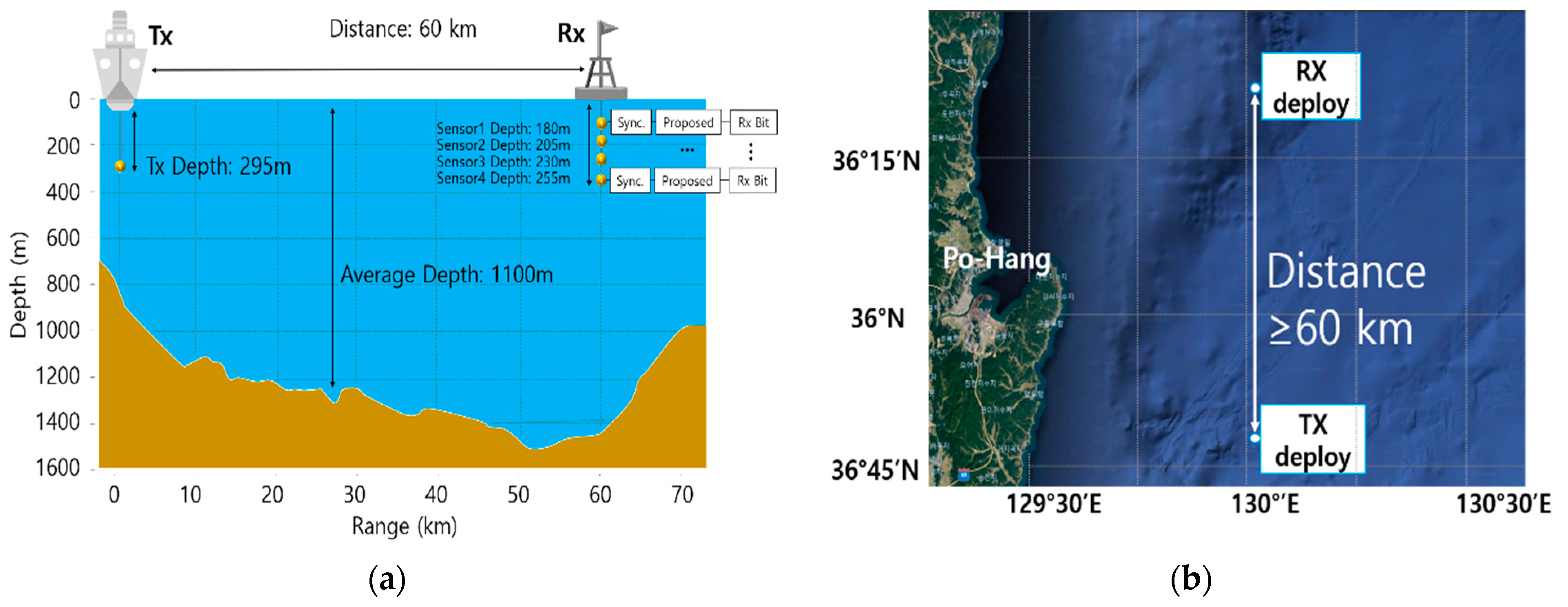
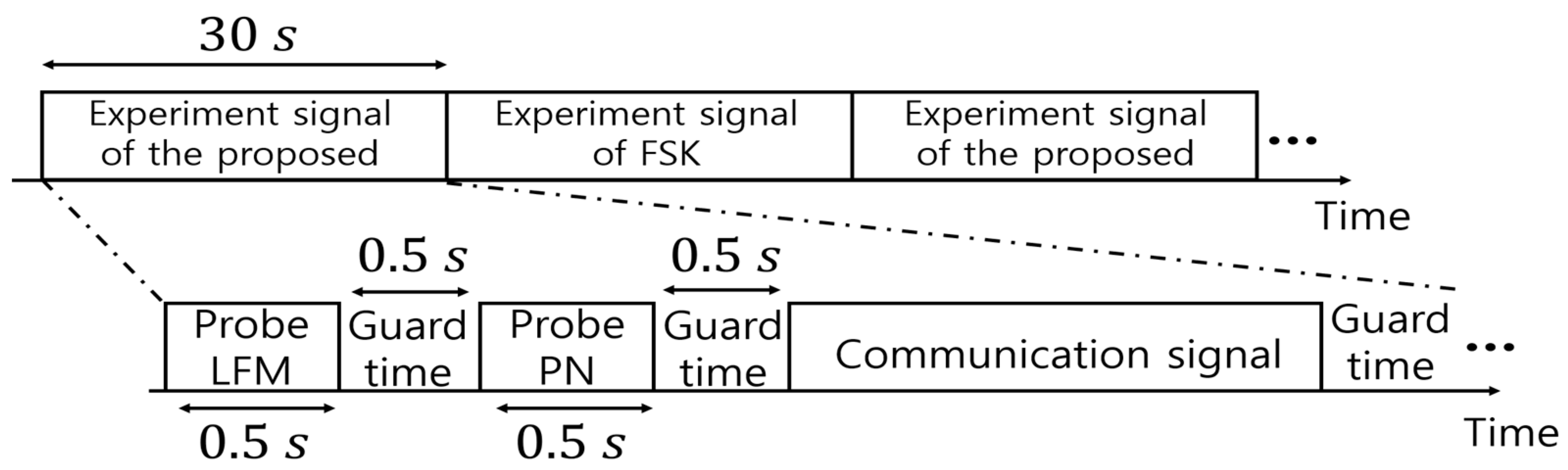
5. Ocean Experiment
6. Conclusions
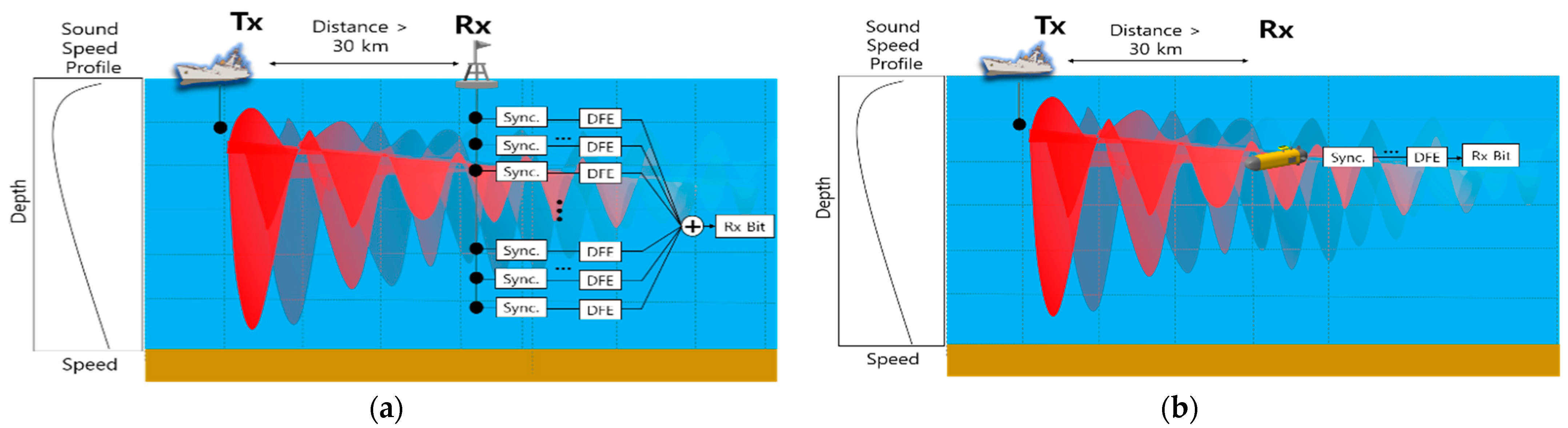
- The novel frequency shift-based modulation/demodulation scheme for long-range UWC with a single receiving hydrophone has been proposed.
- -
- The proposed modulation method transmits the data using LFM suitable for the multi-path delay estimation.
- -
- The proposed demodulation method estimates the multi-path using the previous data signal without a training symbol or FF/FB tap optimization.
- -
- The proposed demodulation method consecutively compensates for received signals using the estimated multi-path.
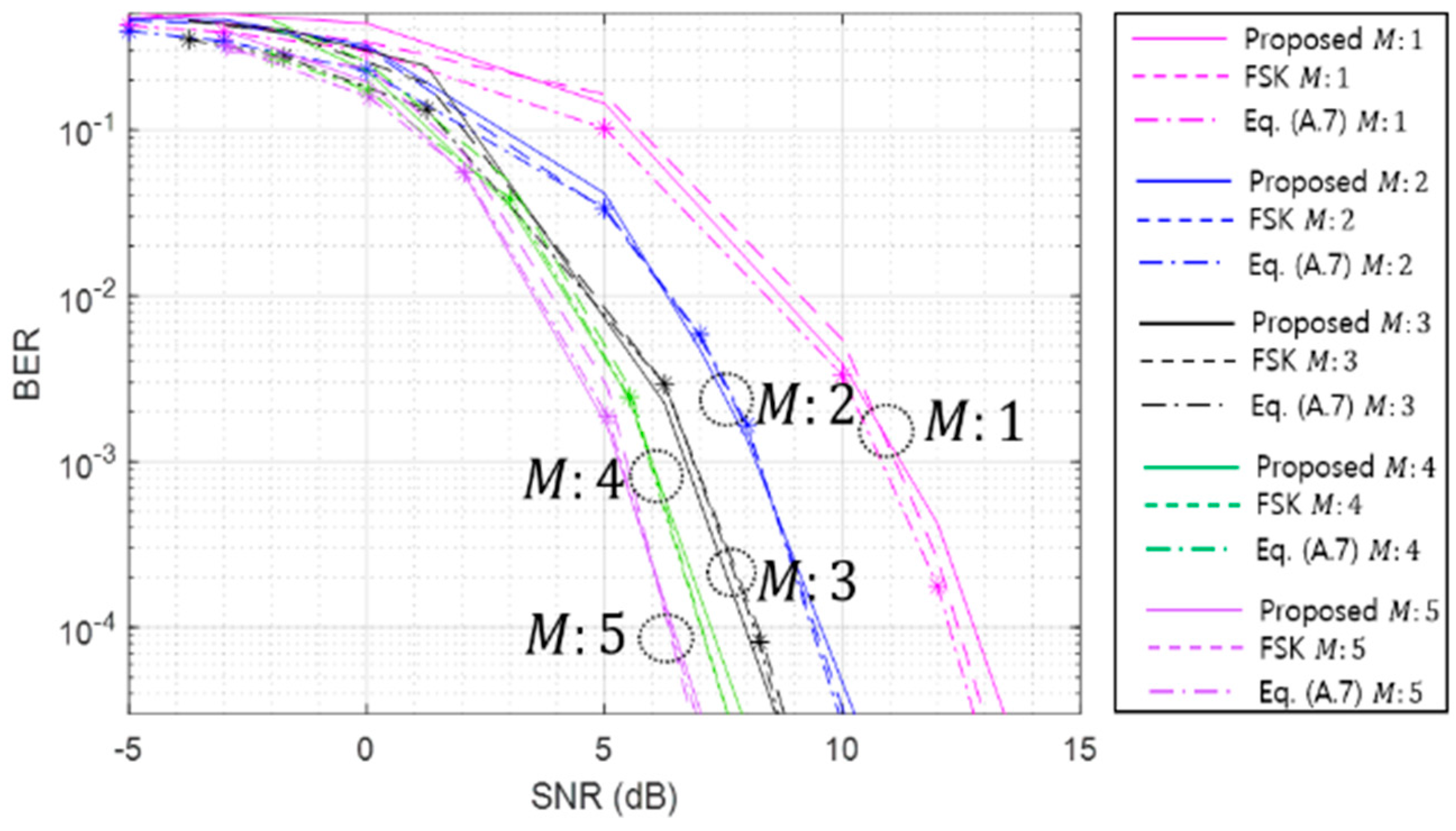
- We conducted computer simulations and practical ocean experiments to demonstrate that the proposed method has a lower BER than the conventional FSK in the long-range UWC environment.
Author Contributions
Funding
Institutional Review Board Statement
Informed Consent Statement
Data Availability Statement
Acknowledgments
Conflicts of Interest
Abbreviations
| Modulation order | |
| Index of start frequency of LFM | |
| Index of end frequency of LFM | |
| Data LFM modulated -th and -th frequencies | |
| Power of LFM | |
| Power of AWGN | |
| Transmitted LFM from TX | |
| Demodulated LFM at RX | |
| Probability of event () | |
| The hypothesis of the case in which the demodulation result of the start frequency symbol () is an error | |
| The hypothesis of the case in which the demodulation result of the end frequency symbol () is an error | |
| The hypothesis of the case in which the demodulation result of the start frequency symbol is correct | |
| The hypothesis of the case in which the demodulation result of the end frequency symbol is correct |
Appendix A


| Modulation order () | 1 | 2 | 3 | 4 | 5 |
| Bandwidth (, Hz) | 50 | 150 | 350 | 750 | 1550 |
| Proposed signal length (, ms) | 40 | ||||
| FSK Signal length ( ms) | 20 | ||||

References
- Stojanovic, M.; Catipovic, J.; Proakis, J.G. Adaptive multichannel combining and equalization for underwater acoustic communications. J. Acoust. Soc. Am. 1993, 94, 1621–1631. [Google Scholar] [CrossRef]
- Shimura, T.; Watanabe, Y.; Ochi, H.; Song, H.C. Long-range time reversal communication in deep water: Experimental results. J. Acoust. Soc. Am. 2012, 132, 49–53. [Google Scholar] [CrossRef] [PubMed]
- Kang, T.; Song, H.C.; Hodgkiss, W.S. Long-range multi-carrier acoustic communication in deep water using a towed horizontal array. J. Acoust. Soc. Am. 2012, 131, 4665–4671. [Google Scholar] [CrossRef]
- Lee, J.H.; Lee, G.H.; Kim, K.M.; Kim, W.J. Sea trial results of long-range underwater acoustic communication based on frequency modulation in East-Sea. J. Acoust. Soc. Kor. 2019, 38, 371–377. [Google Scholar] [CrossRef]
- Ahn, J.H.; Ra, C.H.; Youn, I.H.; Kim, K.M. Experimental results of underwater acoustic communication with nonlinear frequency modulation wave form. J. Sensors 2021, 21, 7194. [Google Scholar] [CrossRef]
- Huang, J.; Diamant, R. Pre-setting of channel types for long range underwater acoustic communications. In Proceedings of the IEEE Oceans, Marseille, France, 17–20 June 2019. [Google Scholar] [CrossRef]
- Huang, J.; Diamant, R. Adaptive Modulation for Long-Range Underwater Acoustic Communication. IEEE Trans. Wirel. Commun. 2020, 19, 6844–6857. [Google Scholar] [CrossRef]
- Song, H.C.; Cho, S.; Kang, T.; Hodgkiss, W.S.; Preston, J.R. Long-range acoustic communication in deep water using a towed array. J. Acoust. Soc. Am. 2011, 129, 71–75. [Google Scholar] [CrossRef] [PubMed]
- Kim, H.; Kim, S.; Choi, J.W.; Bae, H.S. Bidirectional equalization based on error propagation detection in long-range underwater acoustic communication. Jpn. J. Appl. Phys. 2019, 58, SGGF01. [Google Scholar] [CrossRef]
- Pelekanakis, K.; Blouin, S.; Green, D. Performance Analysis of Underwater Acoustic Communications in Barrow Strait. IEEE J. Ocean. Eng. 2021, 46, 1438–1449. [Google Scholar] [CrossRef]
- Kim, D.; Kim, J.; Hahn, J. Long-Range Underwater Communication Based on Time Reversal Processing Using Various Diversity Methods. Sensors 2022, 22, 3138. [Google Scholar] [CrossRef]
- Jinyeong, H.; Junghoon, K.; Yongjin, K. Technology development of unmanned underwater vehicles. J. Comput. Commun. 2017, 5, 25–35. [Google Scholar] [CrossRef]
- Enrica, Z.; Marco, B.; Nikola, M.; Pere, R.; Antonio, P. Challenges and future trends in marine robotics. J. Annu. Rev. Control 2018, 48, 350–368. [Google Scholar] [CrossRef]
- Prasad, M.; Kiran, P.S. Development of Deep Sea Unmanned Underwater Robots: A Survey. In Proceedings of the India Council International, New Delhi, India, 10–13 December 2020. [Google Scholar] [CrossRef]
- Nitin, A. Integrating UUVs for naval applications. J. Marit. Technol. Res. 2022, 4, 3. [Google Scholar] [CrossRef]
- Piskur, P.; Szymak, P.; Jaskólski, K.; Flis, L.; Gąsiorowski, M. Hydroacoustic System in a Biomimetic Underwater Vehicle to Avoid Collision with Vessels with Low-Speed Propellers in a Controlled Environment. Sensors 2020, 20, 968. [Google Scholar] [CrossRef]
- Piskur, P.; Szymak, P. Algorithms for passive detection of moving vessels in marine environment. J. Mar. Eng. Technol. 2017, 16, 377–385. [Google Scholar] [CrossRef]
- Plaisant, A. Long range acoustic communications. In Proceedings of the IEEE Oceans’98, Nice, France, 28 September–1 October 1998. [Google Scholar] [CrossRef]
- Shimura, T.; Ochi, H.; Watanabe, Y.; Hattori, T. Results of Basic At-Sea Experiments on Time-Reversal Communication in the Deep Ocean. In Proceedings of the IEEE Oceans’08, Kobe, Japan, 9–11 April 2008. [Google Scholar] [CrossRef]
- Shimura, T.; Ochi, H.; Watanabe, Y.; Hattori, T. Experiment Results of Time-Reversal Communication at the Range of 300 km. Jpn. J. Appl. Phys. 2011, 49, 07HG11. [Google Scholar] [CrossRef]
- Shimura, T.; Ochi, H.; Song, H.C. Experimental demonstration of multiuser communication in deep water using time reversal. J. Acoust. Soc. Am. 2013, 134, 3223–3229. [Google Scholar] [CrossRef]
- Shimura, T.; Ochi, H.; Watanabe, Y. Time reversal communication in deep ocean results of recent experiments. In Proceedings of the IEEE Symposium on and ’11 Workshop on Scientific Use of Submarine Cables and Related Technologies, Tokyo, Japan, 5–8 April 2011. [Google Scholar] [CrossRef]
- Zhao, A.; Zeng, C.; Hui, J.; Wang, K.; Tang, K. Study on Time Reversal Maximum Ratio Combining in Underwater Acoustic Communications. Appl. Sci. 2021, 11, 1509. [Google Scholar] [CrossRef]
- Youn, C.H.; Ra, H.I.; An, J.H.; Kim, K.M.; Kim, I.S. Experimental analysis of very long range spread spectrum underwater acoustic communication using vertical sensor array. J. Acoust. Soc. Kor. 2021, 41, 150–158. [Google Scholar] [CrossRef]
- Urick, R.J. Principles of Underwater Sound, 3rd ed.; MacGraw-Hill: New York, NY, USA, 1983. [Google Scholar]
- John, L.; Maurice, E.; Chaim, L.P. Propagation of Sound in the Ocean; Geological Society of America: New York, NY, USA, 1948. [Google Scholar]
- Higley, W.J.; Roux, P.; Kuperman, W.A.; Hodgkiss, W.S.; Song, H.C.; Akal, T.; Stevenson, M. Synthetic aperture time-reversal communications in shallow water: Experimental demonstration at sea. J. Acoust. Soc. Am. 2005, 118, 2365–2372. [Google Scholar] [CrossRef]
- Song, H.C.; Hodgkiss, W.S.; Kuperman, W.A.; Akal, T.; Stevenson, M. High-rate synthetic aperture communications in shallow water. J. Acoust. Soc. Am. 2009, 126, 3057–3061. [Google Scholar] [CrossRef] [PubMed]
- Song, H.C.; Dzieciuch, M. Feasibility of global-scale synthetic aperture communications. J. Acoust. Soc. Am. 2009, 125, 8–10. [Google Scholar] [CrossRef] [PubMed]
- Su, Y.; Liu, X.; Jin, Z.; Fu, X. Fast Estimation of Underwater Acoustic Multipath Channel Based on LFM Signal. In Proceedings of the Global Oceans, Biloxi, MS, USA, 5–30 October 2020. [Google Scholar] [CrossRef]
- Ahn, J.; Do, D.; Kim, W. The Long-Range Biomimetic Covert Communication Method Mimicking Large Whale. Sensors 2022, 22, 8011. [Google Scholar] [CrossRef] [PubMed]
- Chung, W.; Johnson, C.; Ready, M. Characterization of multipath distortion of FSK signals. IEEE Signal Process. Lett. 2002, 9, 26–28. [Google Scholar] [CrossRef]
- Fan, W.W.; Liu, L.; Zhang, Y.W.; Dong, J.G.; Sun, D.J. An MMSE Approach to Channel Shorting for Underwater Acoustic FH-FSK Communication. Appl. Mech. Mater. 2014, 511–512, 334–341. [Google Scholar] [CrossRef]
- Ren, H.; Hu, X.; Xu, F.; Jun, X.; Qing, W.; Zhan, C.; Chen, Y. SNR estimation algorithm of LFM signal based on FRFT for long range and shallow underwater acoustic communication systems. In Proceedings of the Oceans 2014, Taipei, Taiwan, 7–10 April 2014. [Google Scholar] [CrossRef]
- Proakis, J.G. Digital Communication, 4th ed.; McGraw-Hill: Boston, MA, USA, 2000; pp. 310–311. [Google Scholar]
- Xiong, F. Digital Modulation Techniques, 1st ed.; Artech House: Boston, MA, USA; London, UK, 2000; pp. 621–625. [Google Scholar]


| Distance (km) | # Path | Max. Delay (ms) | Exp. Name | Year | Ref. |
|---|---|---|---|---|---|
| 89 203 | 3~5 | 40 50 | N/A | 1991 | [1] |
| 50 | 2~4 | 200 | LORACOM | 1996 | [18] |
| 40 100 | 3~4 | 2000 1000 | N/A | 2008 | [19] |
| 300 | 5 | 1000 | N/A | 2010 | [20] |
| 550 | 2 | 30 | LRAC’10 | 2010 | [3,8] |
| 180 500 | 4 6~9 | 300 1500 | KY10-13 | 2010 | [21] |
| 500 700 | 1~2 | 600 | KY11-11 | 2011 | [2] |
| 500 | 15~17 | 2000 | N/A | 2011 | [22] |
| 50 | 2~4 | 60 | N/A | 2015 | [23] |
| 60 | 4 | 190 | BLAC’18 | 2018 | [4,11] |
| 33 | 7~8 | 200 | N/A | 2019 | [10] |
| 20 | 6 | 50 | BLAC’20 | 2020 | [5] |
| 160 | 2 | 100 | ACUA’21 | 2021 | [24] |
| ) | 4 | 3 |
| , Hz) | 750 | 350 |
| , ms) | 40 | |
| ms) | 20 | |
| Modulation order () | 4 | |
| Bandwidth (, Hz) | 750 | |
| Proposed signal length (, ms) | 40 | 80 |
| FSK signal length ( ms) | 20 | 40 |
| Proposed | FSK | |||
|---|---|---|---|---|
| Bandwidth | Proposed Signal Length | Bandwidth | Proposed Signal Length | |
| 3 | 400 (2800–3200) | 40 | 400 (2800–3200) | 40 |
| 4 | 800 (2800–3600) | 40 | 800 (2800–3600) | 40 |
| 4 | 640 (2800–3440) | 50 | 640 (2800–3440) | 50 |
| 5 | 1280 (2800–4080) | 50 | 1280 (2800–4080) | 50 |
| Estimated SNR (dB) | Maximum Delay (ms) | Un-Coded BER | Turbo-Coded BER | |||
|---|---|---|---|---|---|---|
| Proposed | FSK | Proposed | FSK | |||
| 8.87 | <10 | : 3 : 40 ms | N/A | N/A | N/A | N/A |
| : 4 : 40 ms | 0 | 0.008 | 0 | 0 | ||
| : 4 : 50 ms | 0 | 0.009 | 0 | 0 | ||
| : 5 : 50 ms | 0.006 | 0.080 | 0 | 0.008 | ||
| 4.51 | 10~20 | : 3 : 40 ms | 0 | 0.007 | 0 | 0 |
| : 4 : 40 ms | 0 | 0.035 | 0 | 0 | ||
| : 4 : 50 ms | 0.016 | 0.075 | 0 | 0.044 | ||
| : 5 : 50 ms | 0.002 | 0.028 | 0 | 0 | ||
| 2.97 | 20~30 | : 3 : 40 ms | 0.023 | 0.031 | 0 | 0 |
| : 4 : 40 ms | 0.019 | 0.024 | 0 | 0 | ||
| : 4 : 50 ms | 0.045 | 0.080 | 0 | 0.047 | ||
| : 5 : 50 ms | 0.066 | 0.084 | 0 | 0.069 | ||
| 2.45 | 30~40 | : 3 : 40 ms | 0.030 | 0.045 | 0 | 0 |
| : 4 : 40 ms | 0.064 | 0.085 | 0.030 | 0.028 | ||
| : 4 : 50 ms | 0.072 | 0.095 | 0.022 | 0.057 | ||
| : 5 : 50 ms | 0.085 | 0.109 | 0.030 | 0.067 | ||
| −9.12 | >40 | : 3 : 40 ms | 0.224 | 0.211 | 0.205 | 0.167 |
| : 4 : 40 ms | 0.292 | 0.258 | 0.287 | 0.238 | ||
| : 4 : 50 ms | 0.288 | 0.249 | 0.303 | 0.243 | ||
| : 5 : 50 ms | 0.349 | 0.302 | 0.367 | 0.317 | ||
Disclaimer/Publisher’s Note: The statements, opinions and data contained in all publications are solely those of the individual author(s) and contributor(s) and not of MDPI and/or the editor(s). MDPI and/or the editor(s) disclaim responsibility for any injury to people or property resulting from any ideas, methods, instructions or products referred to in the content. |
© 2023 by the authors. Licensee MDPI, Basel, Switzerland. This article is an open access article distributed under the terms and conditions of the Creative Commons Attribution (CC BY) license (https://creativecommons.org/licenses/by/4.0/).
Share and Cite
Ahn, J.; Lee, D.-H.; Lee, S.; Kim, W. Frequency Shift Keying-Based Long-Range Underwater Communication for Consecutive Channel Estimation and Compensation Using Chirp Waveform Symbol Signals. J. Mar. Sci. Eng. 2023, 11, 1637. https://doi.org/10.3390/jmse11091637
Ahn J, Lee D-H, Lee S, Kim W. Frequency Shift Keying-Based Long-Range Underwater Communication for Consecutive Channel Estimation and Compensation Using Chirp Waveform Symbol Signals. Journal of Marine Science and Engineering. 2023; 11(9):1637. https://doi.org/10.3390/jmse11091637
Chicago/Turabian StyleAhn, Jongmin, Dong-Hun Lee, Sangkug Lee, and Wanjin Kim. 2023. "Frequency Shift Keying-Based Long-Range Underwater Communication for Consecutive Channel Estimation and Compensation Using Chirp Waveform Symbol Signals" Journal of Marine Science and Engineering 11, no. 9: 1637. https://doi.org/10.3390/jmse11091637