Article

Compressive–Flexural Failure Mechanism and Bearing Capacity Calculation of Over-Ranging Tapered CFDST Members for Support Structures of Offshore Wind Turbines

1
School of Civil Engineering, Xi’an University of Architecture and Technology, Xi’an 710055, China
2
Department of Civil Engineering, Xi’an Jiaotong University, Xi’an 712000, China
3
School of Civil Engineering and Architecture, Xi’an University of Technology, Xi’an 710048, China
*
Authors to whom correspondence should be addressed.
J. Mar. Sci. Eng. 2023, 11(8), 1621; https://doi.org/10.3390/jmse11081621
Submission received: 17 July 2023 / Revised: 12 August 2023 / Accepted: 17 August 2023 / Published: 19 August 2023
(This article belongs to the Special Issue Advances in Marine Structures)

Abstract

:
Upon the higher requirement on high-performance structures of large-scale supporting structures of offshore wind turbines, the systematic analysis on the compressive-flexural behavior and ultimate bearing capacity of tapered concrete-filled double skin steel tubular (CFDST) members designed by over-ranging parameters was performed. Investigating the entire-process mechanism, e.g., the moment–deformation response, stress development, interaction stress, and subassembly contribution, was based on the finite element (FE) analysis, where the moment–deformation curve can be distinguished by four characteristic points, and the transverse local buckling of outer tube partly weakens distribution height of interface pressure in compression zone compared to that in tension zone. Influences of material strengths and geometric parameters were examined by the parametric study, e.g., increasing tapered angle (ψ) slightly reduces the bearing capacity; the higher axial compression ratio (n) contributes a noteworthy action on the post-peak behavior and carrying capacity, e.g., the bearing capacities at n = 0.9 and n = 0.5 reduce by 64.14% and 18.44% compared to capacity at n = 0.1, respectively; influence of Do/to ratio is more significant than Di/ti ratio. Subsequently, the modified cross-sectional stress integration (CSI) method was proposed to predict the moment–strain (M-ε) curves of tapered CFDST members; meanwhile, a confined concrete model with transverse confinement stress as an explicit parameter was modified, and influences of different confined concrete models on predicting M-ε curves were compared. Finally, design methods based on the modified CSI method and limit state method were proposed as a simplified calculation method to determine the correlative relationship of axial compressive strength and moment-resisting capacity (N-M curve).

1. Introduction

In recent years, the offshore wind power support structures gradually tend to be large-size upon the obvious improvement of installed capacity of a single wind turbine, e.g., the rotor radius, radial height of blade, and hub height of Haliade-X with installed capacity of 12 MW, respectively, achieve 110 m, 107 m, and 135 m; therefore, to resist the extreme loads, an urgent demand on the high-performance support structures is required for promoting offshore wind turbines towards abyssal pelagic zone [1,2,3]. Notably, under the gale or intense earthquake motion, several problems of construction and design, including enormous steel cost, controlling difficulty for lateral deformation, and higher instability or failure risk, usually prevent traditional hollow steel tubular sections from behaving the remarkable structural performance in those support structures of tower barrel, jacket, or pile foundation [4,5,6,7,8]. The development of high-performance support structures should be given great importance; meanwhile, the compressive-flexural behavior as the typical working condition of the whole life cycle basically determines service feasibility and safety margin for support structures [6,7,8,9,10]. To pursue an optimized structure scheme, the tapered concrete-filled double-skin steel tubular (CFDST) structures that originate from tapered CFSTs (concrete-filled steel tubes) and straight CFDST (SCFDST) structures gradually attract the attention of engineers and investors due to their reasonable mechanical behavior (Figure 1), for which the composite performance between double-skin steel pipes and hollow concrete infill can ameliorate the local buckling of steel tubes for improving cross-sectional stiffness, strength, and ductility [11,12,13]. For tapered CFDST (TCFDST) members, a competitive utilization future in support structures for offshore wind turbines can be therefore expected. Moreover, to be successfully utilized in ocean engineering, large hollow ratios (χ), as well as the over-ranging diameter-to-thickness (D/t) ratios that will exceed the specified values in existing design codes, are usually required for reducing the self-weight and steel cost for enhancing its installation efficiency [14,15,16]. It is also necessary to investigate the compressive-flexural behavior of tapered CFDST members with over-ranging design parameters.
Many studies until now mainly aimed at the performance of SCFDST (straight CFDST) or TCFDST (tapered CFDST) members under concentric pressure, tension, bending, or torque moment [11,12,13,14,15,16,17,18,19,20,21,22,23,24,25]. Li et al. [26] studied the eccentric compressive performance for TCFDST specimens (χ = 0.59~0.67 at the top section), indicating that the TCFDST specimens behave an overall bending failure that is accompanied by the apparent lateral deformation above the member middle. Han and Wang [27] numerically studied the behavior of TCFDST specimens loaded by the combination of shear and concentric compression, in which hollow ratios, tapered degree, and concrete strength have a slight influence on the ultimate bearing capability. Shi et al. [28] analyzed the mechanical performance and design method of TCFDST columns under eccentric compression, where the disabled location subjected to the eccentric compression changes from the middle section of straight members to the three-quarter height of tapered members. Subsequently, Shi et al. [29] researched the hysteretic performance of TCFDST specimens by the test and numerical modeling, in which it revealed that there is a slight influence on bearing capacity and ductility as enhancing hollow ratio (bottom section) from 0.6 to 0.8. Compared to the abundant research under axial compression, study on the compressive-flexural behavior is insufficient for TCFDST members under the scenario of large hollow ratios (χ ≥ 0.7) and tapered angle (ψ ≥ 0.6°), and over-ranging D/t values. A non-determinacy to enhance the ductility and bearing capacity may exist for the constraint action between the concrete infill and double-skin pipes, against the situation of over-ranging design parameters (e.g., D/t values and hollow levels); moreover, dependability and feasibility of the calculation method in currently various standards are still uncertain in that case [30,31,32]. Moreover, the current calculation method on the combination of concentric compression and bending moment is usually developed from the empirical formula with more coefficients needed for further calibration. The simplified and high-efficiency computing method for the bearing capacity characteristic can still be improved for TCFDST members, especially for those members with over-ranging design parameters. That is also the main objective and innovative work in this paper. Regarding the requirement of light weight and higher construction speed in the ocean environment, the mechanical behavior, calculation, or design method should be systematically investigated in order to improve the disaster resistance of those over-ranging tapered CFDST members, guiding the structural design, e.g., bearing capacity check and parameter matching.
Therefore, this paper conducted analytical research on the compressive-flexural performance and calculation method of over-ranging tapered CFDST members for supporting structures of offshore wind turbines. A finite element (FE) modeling was conducted to investigate the whole process mechanism, including carrying capacity contributions, confinement action, and stress development; subsequently, the parametric analysis based on geometric-physical parameters was carried out for reflecting its influences. A theoretical simplified model was suggested to predict the moment–deformation (M-ε) curve, and the corresponding methods for determining axial strength versus moment (N-M) curves were also developed. Through the study in this paper, several design suggestions and references under the over-ranging parameters will be obtained to guide the structural design and engineering application.

2. Finite Element Modeling

2.1. FE Model

The five-stage constitutive curve (displayed in Figure 2) was utilized to calculate the elastic-plastic performance of steel pipe [33]:
σ s = E s ε s ε s ε e A ε s 2 + B ε s + C ε e < ε s ε e 1 f y ε e 1 < ε s ε e 2 f y 1 + 0.6 ε s ε e 2 ε e 3 ε e 2 ε e 2 < ε s ε e 3 f u ε s > ε e 3
where the parameters of εe, εe1, εe2, εe3, A, B, C, and fu can be derived from the literature [33]. The following stress–strain relationship in Equation (2) was used to depict the compressive response of sandwich concrete [34,35].
y = 2 x x 2 ( x 1 ) x β 0 ( x 1 ) 2 + x ( x > 1 )
where x = ε ε 0 is the dimensionless strain and y = σ f c is the non-dimensional stress. The peak strain ε0 and computing coefficient β0 are given as follows.
ε 0 = ( 1300 + 12.5 f c ) × 10 6 + 800 ξ 0.2 × 10 6 β 0 = ( 2.36 × 10 5 ) [ 0.25 + ( ξ 0.5 ) 7 ] ( f c ) 0.5 0.5 0.12
where ξ is the confinement factor [36]. Regarding the tensile performance of sandwich concrete, the constitutive curve in Equation (4) was employed in FE model [37].
y = 1.2 x 0.2 x 6 ( x 1 ) x 0.31 σ pt 2 ( x 1 ) 1.7 + x ( x > 1 )
where x = ε ε pt is the non-dimensional tensile strain; and y = σ σ pt is the dimensionless tensile stress. The tensile strength (σpt) as well as its matched strain (εpt) can be determined through the method below.
σ pt = 0.26 × ( 1.25 f c ) 2 / 3 ε pt = 43.1 σ pt ( μ ε )
In the FE model of ABAQUS program, the reduced integral element modes of the solid (C3D8R) and shell (S4R) were severally adopted for the hollow concrete infill and steel pipe. To simulate the interfacial behavior between the hollow concrete infill and tapered steel pipes, the hard contact in the normal direction and Coulomb friction method in the tangential orientation were respectively utilized [34,36]. The friction factor was 0.6. To fully verify the applicability of established FE model, two types of compressive-flexural loading conditions were formed based on existing test results [28,29]. In Figure 3, the first one is to apply lateral load on the top section after loading the axial compression; the second is loaded with eccentric compression. The numerical models are consistent with the test loading condition. Sixty elements (25 mm) and thirty-two elements were equally divided along the height and circumference for the steel pipes and hollow concrete infill, respectively; therefore, the coordinate error of element nodes can be avoided for improving computational efficiency; subsequently, the four-layered gridding was equivalently meshed for the concrete’s thickness orientation. The column bottom section was in the stationary boundary, and the upper section was coupled to the referential points (RP-1 or RP-2) for achieving loading. During the ABAQUS simulation procedure in general static step, the simulated output was obtained by the Newton–Raphson iteration way.

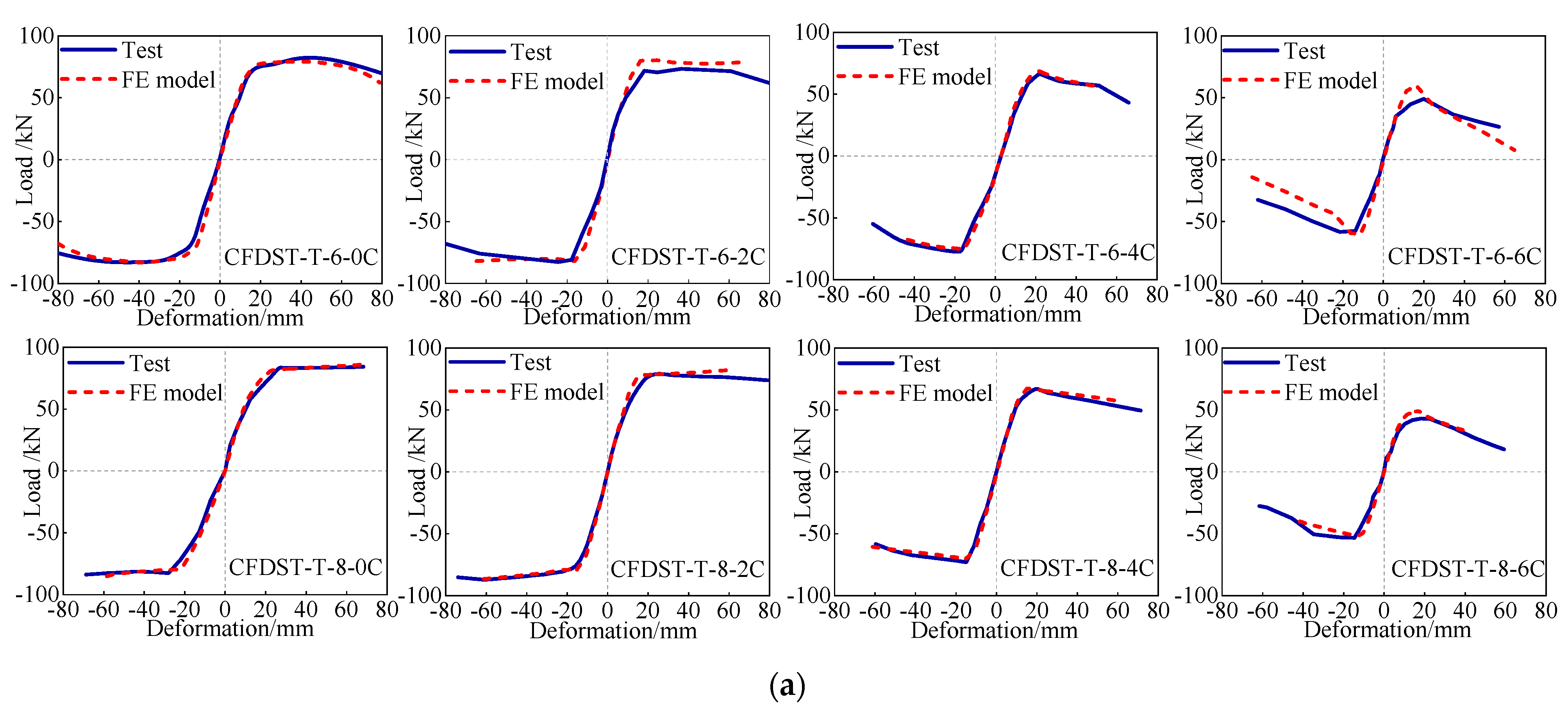
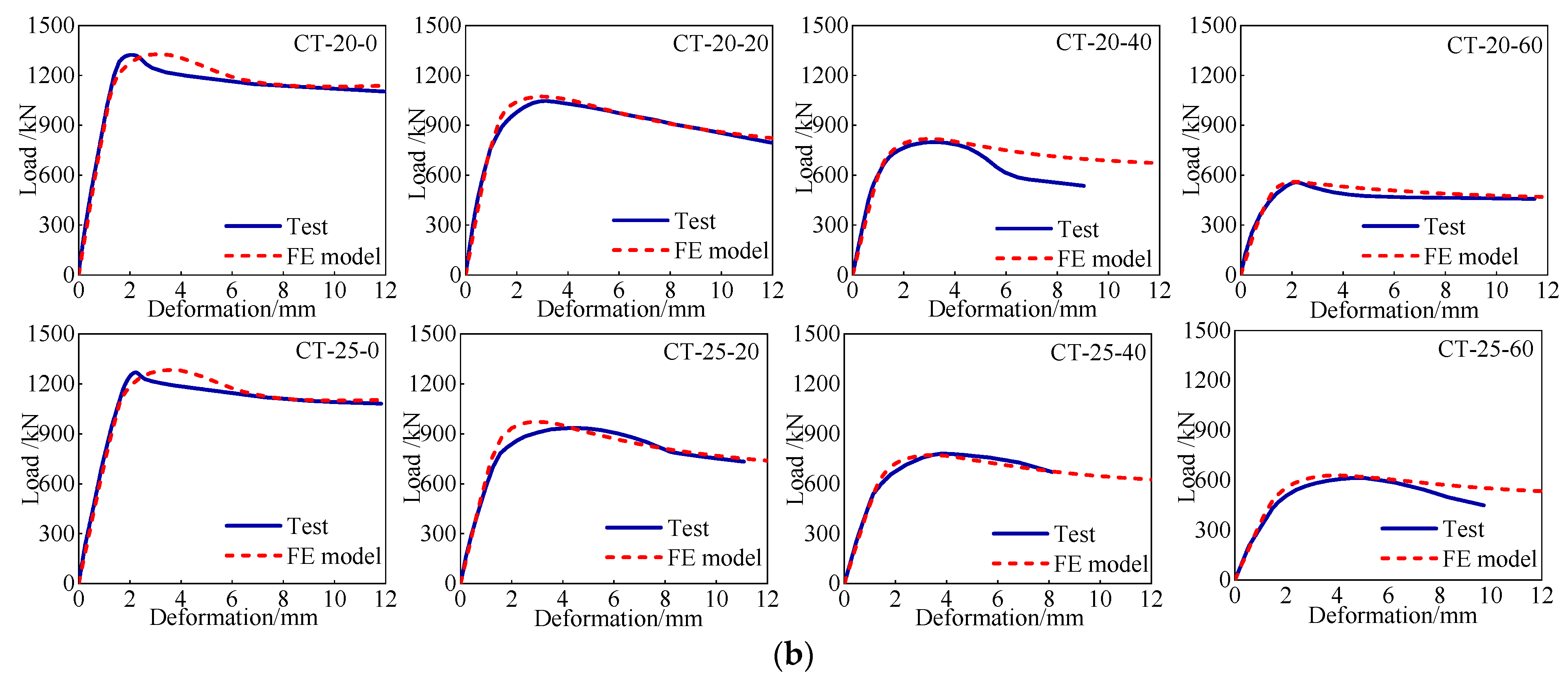
2.2. Validation of FE Model

To validate the established model, the collected test results of existing studies was gathered and compared by the failure mode and load–displacement response. Because of the limited test study on compressive-flexural behavior of tapered CFDST members, the FE model was validated by different loading schemes according to Figure 3. As displayed in Figure 4, the predicted failure pattern of FE models is, respectively, achieved by the local buckling of column base (loading type 1) and upper section (loading type 2), agreeing well with the test data. As for the full-range curves (Figure 5), the FE curves of load versus displacement generally match well with the pre-peak stiffness, maximum carrying strength and nonlinear response of post-peak stage for tested tapered CFDST members, in which the load and displacement in Figure 5a represent respectively the lateral load and lateral deflection of top section; the load and displacement in Figure 5b, respectively, indicate the eccentric compression and lateral deformation at H/4 height versus top section. Because of the damage randomness or strength deviation of the actual test material, a slightly higher ultimate carrying capacity than test data occurs, for example the CFDST-T-6-2C and CT-25-20. On the whole, the displayed FE model can accurately reflect the compressive-flexural performance of tapered CFDST specimens, and the mechanism investigation and parametric analysis will be performed based on that.

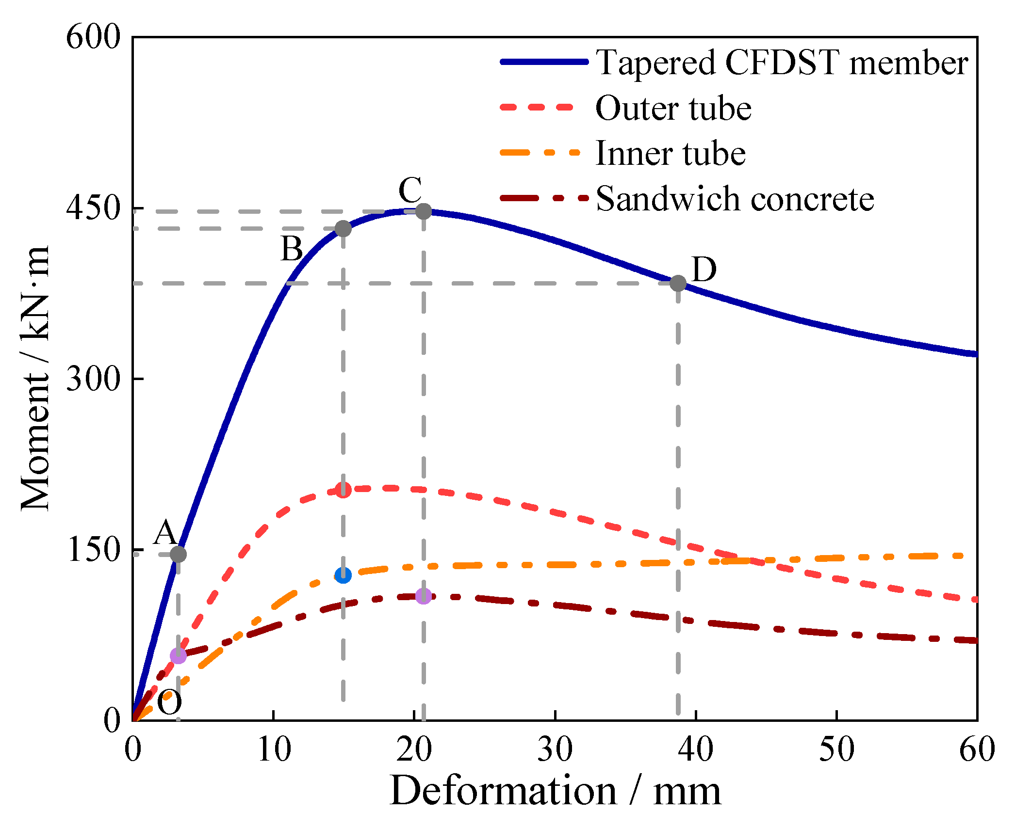
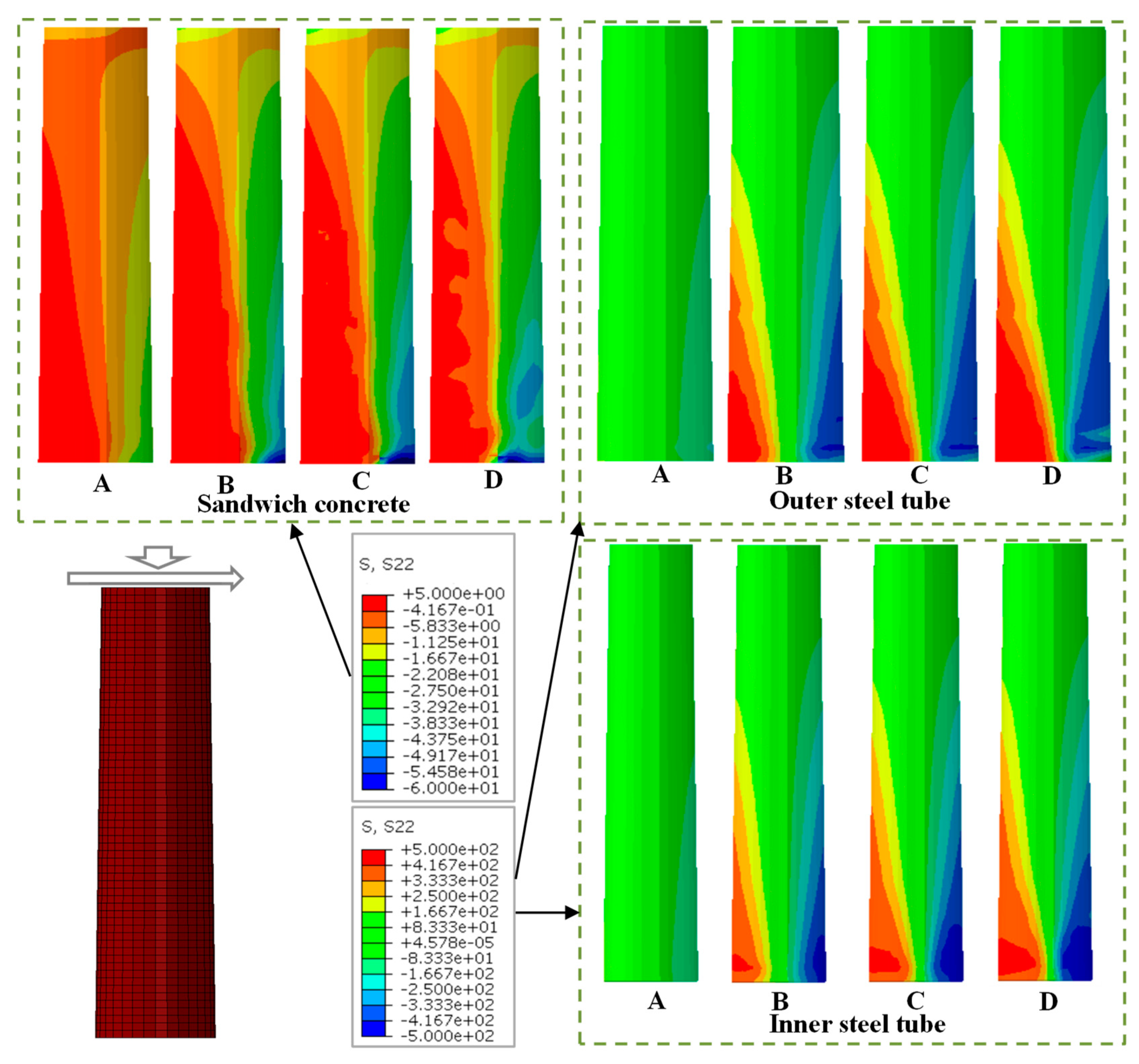
2.3. Whole-Process Mechanism Analysis

According to the validated numerical method, the entire-range performance of over-ranging tapered CFDST members is offered; meanwhile, a typical specimen was discussed for the demonstration. In Chinese design standard of T/CCES 7-2020, the specified hollow rate value is suggested between the scope of 0.2~0.75, and its D/t values should match the specification of D/t ≤ 100·235/fy. The abovementioned benchmark member is given as: the tapered angle (ψ) is 0.76°; outer tube’s diameter at specimen base (Dob) is 400 mm; outer tube’s diameter at specimen top (Dot) is 360 mm; inner tube’s diameter at member bottom (Dib) is 325 mm; inner tube’s diameter at member top (Dit) is 285 mm; the inner/outer tube’s thickness (ti or to) is 3 mm; the hollow ratio (χ) at the upper section is 0.81, obviously larger than the design limitation of 0.75; steel yield strengths of outer (fyo) or inner tubes (fyi) are 420 MPa; the effective height (H) is 1500 mm; the cubic concrete strength under compression (fcu) is 50 MPa. The calculated D/t values at member top of outer and inner pipes are respectively 120 and 95, exceeding the requirement limitation by 114.29% and 69.64%, respectively. Moreover, the offshore wind support structures are usually subjected to the self-weight and lateral load action (e.g., wind, wave and earthquake); hence, the loading type 1 in Figure 3, namely the combination of axial compression and lateral load, is close to the practical service state. Therefore, the compressive-flexural performance and mechanism of over-ranging TCFDST members are mainly investigated based on the loading type 1. Mechanism analysis is displayed in Figure 6, Figure 7, Figure 8, Figure 9 and Figure 10.
As shown in Figure 6, four feature points (points A~D) can distinguish the curve into various performance stages. In stage OA, the member behaves an elastic performance, and at point A the sandwich concrete in tensile zone is cracked (Figure 7). Thereafter, the plastic response of double-skin tubes and sandwich concrete gradually extends in stage AB. At point B, the member bottom appears the yielding phenomenon of double-skin pipe wall as displayed in Figure 7, at which the outer steel tube, inner steel tube and concrete infill respectively occupy 46.88%, 29.53%, and 23.59% of whole bending capacity to the tapered CFDST specimen. During stage BC, the trend of the moment–displacement curve increases slowly, indicating the deep plasticity of tapered specimens. The ultimate carrying strength is realized at the point C, where the outer pipe, inner pipe and hollow concrete infill respectively contribute 45.31%, 30.27% and 24.42% of the total capacity. Subsequently, the tapered CFDST specimen enters into post-peak stage accompanied with degradation of stiffness and ultimate carrying capacity. The contribution of inner tube is enhanced gradually because of the outer tube’s local instability; meanwhile, the contribution curve for inner tube displays the slight hardening phenomenon because of the confinement support of sandwich concrete. Bearing capacity at point D means the 85% of maximum capacity at point C. From the development of bending normal stress (Figure 7), the concrete infill cracking nearly distributes along full height of member, however, the yielding zone or plastic region of steel tubes usually focuses on the member base. The neutral axis locates inside the inner tube.
To investigate the constraint response between tapered steel tubes and hollow concrete infill, the interface pressure is depicted and analyzed in Figure 8 and Figure 9. The height value of abscissa is given in Figure 10. It can be found in Figure 8 that the interface pressure gradually increases along the height direction, where the interface pressure in compressive zone is motivated within the height larger than 0.7H, while the interface pressure in tensile zone occurs in the range of 0.4H~H. The interfacial coaction of outer pipe wall versus hollow concrete infill is effectively located in member base, and the transverse deformation trend of local buckling under compression partly weakens distribution height of interface pressure compared to that in tensile zone, e.g., interface pressure of point B in compressive zone versus value of point B in tensile zone. Moreover, with the loading increase, namely from feature point A to point D, the interface pressure is enhanced at the same height, e.g., for the maximum load of point C, the interface pressures have higher values of 1.50 MPa at 0.93H for compressive zone and 2.32 MPa at 0.95H for tensile zone, respectively. The interfacial pressure (in Figure 9) of inner pipe and concrete infill has a similar tendency with Figure 8 along the height direction, but interface pressure of compressive zone is within the height 0.8H~H, larger than that in tensile zone, which is ascribed to that sandwich concrete in compressive zone obviously restricts the transverse local buckling of inner tube, therefore making a more compact interface contact than that in tensile zone. Generally, the interface pressure between inner tube and concrete infill is smaller compared to the values in Figure 8, especially in Figure 9b the interface pressures of points A and B are approximately close to zero, reflecting that constraint action to sandwich concrete infill nearly is induced by the outer steel tube.

2.4. Parametric Study

The parametric analysis was carried out to examine the actions of various key factors upon the validated numerical model. The benchmark member in Section 2.3 was adopted. Influences of investigated parameters on curves of load versus displacement and ultimate carrying strength are given in Figure 11 and Figure 12, respectively.
Improving the tapered angle (ψ) reduces the stiffness and maximum carrying strength slightly, as displayed in Figure 11a and Figure 12a; meanwhile, the carrying capacity approximately decreases in the linear type, for example, improving tapered angle from 0° to 1.15°, 1.72°, and 2.10°, the capacity respectively reduces by 1.93%, 3.15%, and 4.09%, which is owing to the fact that the tapered angle’s increment makes a reduction of sectional area that is significant for the total ultimate carrying capacity. As for the effect of hollow ratio (χ) in Figure 11b and Figure 12a, with the enhancement of hollow ratio before χ = 0.66 the carrying capacity is enhanced gradually, e.g., the capacity at χ = 0.66 is increased by 9.77% versus the capacity at χ = 0.31; thereafter, the ultimate carrying capacity of tapered CFDST specimen is decreased, especially for the specimen with hollow ratio χ = 0.95, its full-range load–displacement curve has a severely degraded post-peak stage compared to the others, where its capacity is obviously declined by 12.24% compared to the capacity at χ = 0.66. But within the range of χ = 0.45~0.88, the full-range load–displacement curves as well as its bearing capacities behave similarly in pre/post-peak stages, reflecting though the area of sandwich concrete will be reduced as increasing the hollow ratio to a higher level (e.g., χ = 0.88 versus χ = 0.52), the increasing inertia moment of inner steel tube cannot produce the apparent reduction on carrying capacity. Therefore, the calculation result indicates that appropriately enhancing hollow ratios based on the limitation of the existing design code can also obtain reasonable compressive-flexural behavior, light self-weight, and capacious inspection gallery on the premise of safety margin. The effect of concentric compression ratio (n) is offered in Figure 11c and Figure 12a, where a small deviation exists in the initial stiffness as increasing axial compression ratio, but makes a significant impact on the post-peak response and carrying capacity, after n = 0.1 the decline speed of carrying capacity improves increasingly, for example, the capacities at n = 0.9 and n = 0.5 reduce by 64.14% and 18.44% compared to member at n = 0.1, respectively.
In Figure 11d,e and Figure 12b, the influence of the Do/to value and Di/ti value is analyzed by varying the wall thicknesses but keeping its diameter unchanged. The result indicates that improving D/t values of steel pipes (namely the outer or inner tube) gradually decreases its bending stiffness and carrying capacity, owing to the obvious decline of constraint action, for example, the maximum bearing strength is respectively decreased by 18.68% and 28.47% as increasing Do/to value from 60 to 80 and 120, and it is respectively decreased by 16.27% and 24.73% as increasing Di/ti ratio from 57 to 95 and 142. The influence of the Do/to ratio is more significant than the Di/ti ratio. Furthermore, the influence of material strength is displayed in Figure 11f,g and Figure 12c. In this parametric study, altering steel yield strength is realized by simultaneously changing the strength of double-skin tubes. Strength enhancement (yielding strength fy and compressive cubic concrete strength fcu) produces an approximately linear increase trend, e.g., the ultimate carrying capacity at fy of 460 MPa is increased by 6.55% versus the specimen with fy of 420 MPa. As for the action of strength fcu, increasing fcu from 30 MPa to 70 MPa makes the carrying capacity increase by 18.71% in Figure 11g and Figure 12c. The carrying capacity growth rate of concrete at every enhancement of 10 MPa is higher than that of steel pipes, because the sectional area of hollow concrete infill occupies most of the whole section of CFDST member.

3. Simplified Method for Predicting Moment–Strain Curve

The abovementioned result indicates that strength failure at key cross-section occurs and determines the ultimate carrying strength of structures. Therefore, in this section, the modified cross-sectional stress integration (CSI) method is proposed as the simplified evaluation tool to calculate the moment–strain (M-ε) curves and carrying capacity, for avoiding the tanglesome calculation procedure of the finite element method. The method’s detail and verification are given below.

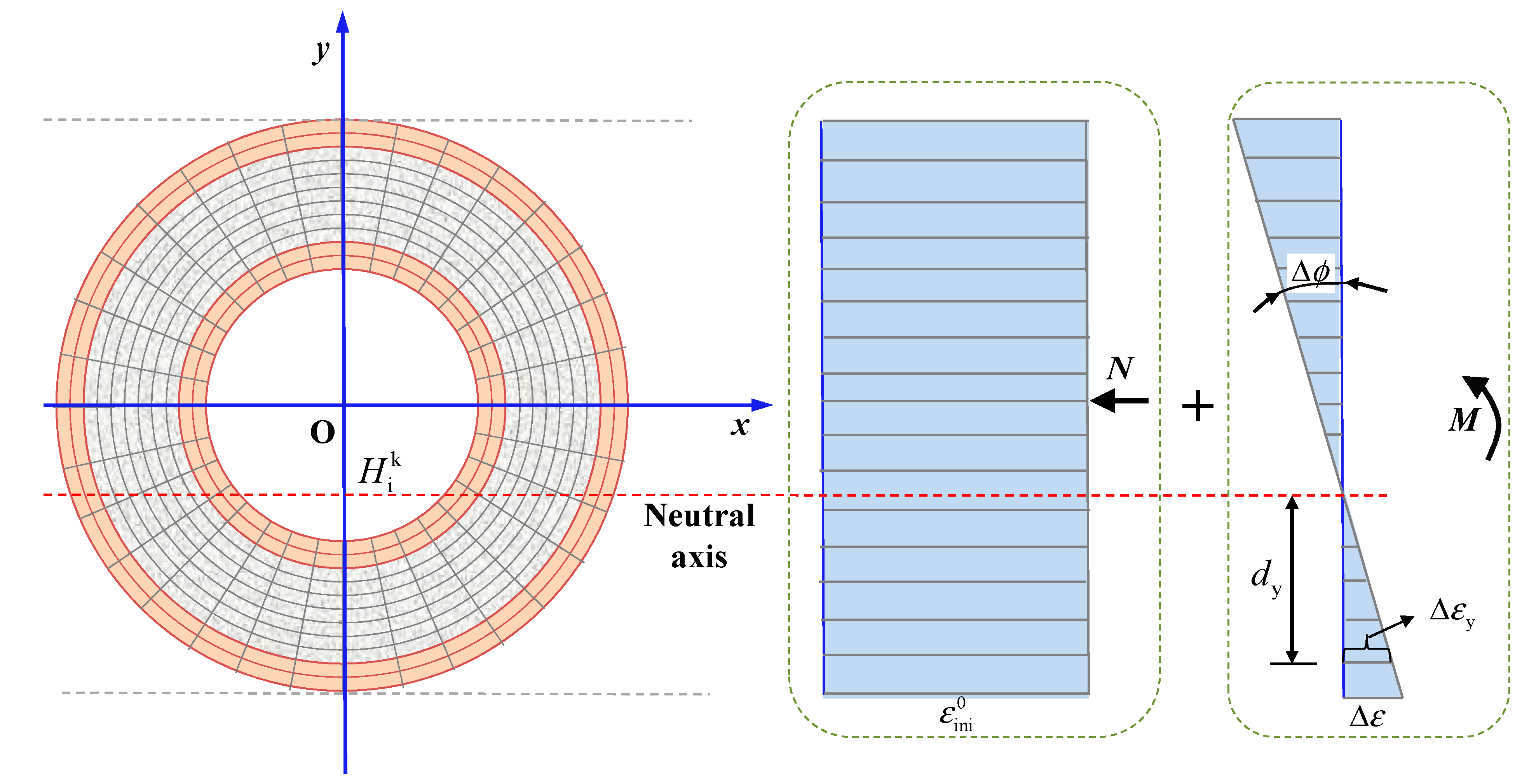
3.1. Method Description and Establishment

As the CFDST specimens are in the coaction of concentric pressure and flexural moment, it is assumed that: (i) the plane cross-section is maintained when subjected to flexural deformation; (ii) there is no interfacial sliding of the tube wall and concrete infill; (iii) the tensile concrete strength is ignored. The schematic diagram of the modified CSI method is shown in Figure 13.
The bending strain increment at specific height (Δεy) in Figure 13 can be derived from the strain increment Δε of outer tube edge in tension zone, as shown in Equations (6) and (7).
tan ( Δ ϕ ) = Δ ε 0.5 D o + H i k
Δ ε = f ( Δ ε , H i k ) = tan ( Δ ϕ ) d y Tension   zone tan ( Δ ϕ ) d y Compression   zone
Subsequently, the total strain under combination of axial compression and bending moment can be superposed by the multiple iterations:
ε so i = ε so i 1 + f ( Δ ε , H i k ) ε si i = ε si i 1 + f ( Δ ε , H i k ) ε con i = ε con i 1 + f ( Δ ε , H i k ) ε so 0 = ε si 0 = ε con 0 = ε ini 0
Especially, the initial state ( ε so 0 , ε si 0 and ε con 0 ) is equal to the strain under axial compression ( ε ini 0 ). Adding the bearing capacities of inner/outer pipes and hollow concrete infill can obtain the concentric load and moment-resisting capacity:
N = N so + N si + N con = i = 1 n so , c j = 1 n so , r σ so , i , j A so , i , j + i = 1 n si , c j = 1 n si , r σ si , i , j A si , i , j + i = 1 n c o n , c j = 1 n con , r σ con , i , j A con , i , j
M = M so + M si + M con = i = 1 n so , c j = 1 n so , r σ so , i , j A so , i , j y so , i , j + i = 1 n si , c j = 1 n si , r σ si , i , j A si , i , j y si , i , j + i = 1 n con , c j = 1 n con , r σ con , i , j A con , i , j y con , i , j
The above naming rule is also suitable to inner tube and sandwich concrete, namely the stresses (σsi,i,j and σcon,i,j), areas (Asi,i,j and Acon,i,j), element distances (ysi,i,j and ycon,i,j), and element numbers (nsi,c, nsi,r, ncon,c, and ncon,r).
To calculate the stress of steel pipes, an ideal elastic-plastic constitutive curve was adopted [38]. Moreover, to determine the compressive stress of sandwich concrete, two different confined concrete models (CCM) were utilized. The first one (CCM 1) is the equivalent uniaxial constitutive relationship for fiber element modeling proposed by Han [39]:
y = 2 x x 2 ( x 1 )
y = 1 + q ( x 0.1 ξ 1 ) ( ξ 1.12 ) x β ( x 1 ) 2 + x ( ξ < 1.12 ) ( x > 1 )
The coefficients in Equations (11) and (12) are given as follows:
ε 0 = ( 1300 + 12.5 f c ) + 1400 + 800 f c 24 ξ 0.2 ( μ ε )
σ o = 1 + ( 0.054 ξ 0.2 + 0.4 ξ ) f c 24 0.45 f c
q = ξ 0.745 2 + ξ
β = ( 2.36 × 10 5 ) [ 0.25 + ( ξ 0.5 ) 7 ] ( f c ) 2 3.51 × 10 4
The abovementioned parameter notation is the same as that in Section 2.1. Actually, the strength of confined sandwich concrete has a significant dependency on transverse confinement stress (σr) that is not directly expressed in the abovementioned model; therefore, this paper developed a modified confined concrete model (CCM 2) with transverse confinement stress (σr) as an explicit parameter [40,41].
σ c = f cc 1 1 ε cc ε 0 c 2 0 ε cc < ε 0 c f cc ε 0 c ε cc ε cuc
f cc = f c ( 1.000 + 5.0 σ r / f c ) σ r 0.05 f c f c ( 1.125 + 2.5 σ r / f c ) σ r > 0.05 f c
ε 0 c = ε 0 ( f cc / f c ) 2 ε cuc = ε cu + 0.2 σ r / f c ε 0 = 0.0020 + 0.5 ( f cu 50 ) 10 5 ε cu = 0.0033 ( f cu 50 ) 10 5
where fcc is the compressive strength of confined concrete; fc and fcu are the compressive strengths of unconstrained concrete, indicating the cylinder and cubic strength, respectively. The transverse confinement stress (σr) is assumed a function of Do/to value and Di/ti value:
σ r = f D o t o , D i t i = β α 1 + α 2 D o t o + α 3 D i t i + α 4 D o t o 2 + α 5 D o t o D i t i + α 6 D i t i 2 β = N N u γ
where α1~α6 are the calculation coefficients; β is the influence coefficient induced by axial compression ratio, γ is the undetermined exponent; N is the concentric compression, and Nu is the compressive strength of CFDST members. Therefore, in Figure 14, the nonlinear fitting method was employed to determine the mentioned parameters in Equation (20) based on existing test results of CFDST members [14,16,19,42,43], and the final expression of transverse confinement stress (σr) is given in Equation (21).
σ r = f D o t o , D i t i = N N u 15.72 + 10 4 6 D o t o 2 3 D i t i 2 + 6 D o t o D i t i 2293 D o t o 60 D i t i
As mentioned above, the modified model should be transformed into the equivalent cross section to evaluate the compressive–flexural behavior of tapered CFDST members; the transformation formula is shown in Equations (22) and (23) [32].
D eo = ( 1 k ot ) ( D ob D ot ) + D ot D ei = ( 1 k ot ) ( D ib D it ) + D it
k ot = 0.6 + 0.26 χ ( ψ + 1 ) 1.5 χ ( ψ + 1 ) 1.5 0.86 χ ( ψ + 1 ) > 1.5
Finally, the whole moment–strain behavior can be determined by the suggested modified CSI model.

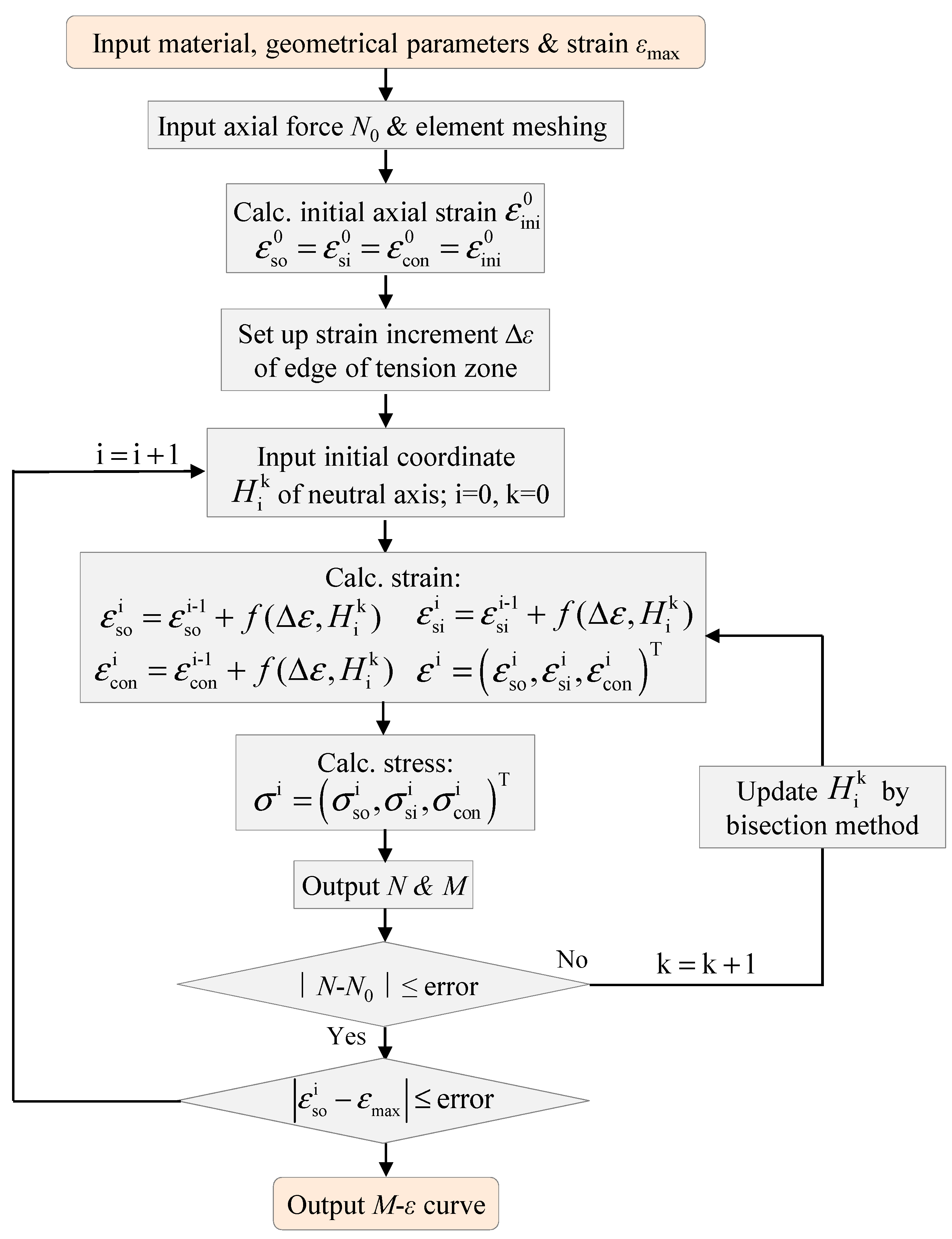
3.2. Calculation Procedure

Upon the modified CSI model, the compiled subroutine was established. The detailed calculation step is demonstrated in Figure 15:
(1)
Input material and geometric details, and input maximum strain of terminal condition;
(2)
Input axial force and conduct element meshing;
(3)
Calculate the initial strain under axial compression;
(4)
Set up strain increment Δε of outer tube edge in tension zone;
(5)
Calculate the strain of steel tubes and concrete infill based on Equations (6)–(8);
(6)
Calculate the stresses of components based on constitutive models of steel and concrete;
(7)
Output axial force and moment-resisting capacity through Equations (9) and (10);
(8)
Carry out error judgment of axial force; if allowed, enter into the next step, otherwise, update coordinate value of neutral axis until reaching convergence;
(9)
Conduct error judgment of terminal condition by multiple iterations;
(10)
Output M-ε curve of tapered CFDST member.

3.3. Verification of Proposed Method

For the tapered CFDST members, so far there are no available measuring data of strain development of outer steel tube in tension zone at column base. To validate the proposed modified CSI method, the calculation result of CSI method was compared to the results of the verified FE model in Section 2, meanwhile, the different constitutive models of confined concrete were validated. The verification results are given in Figure 16 and Figure 17. It indicates that the predicted results of modified CSI method based on CCM 1 or 2 achieve a reasonable agreement with the calculation results of the refined FE model. In Figure 16 and Figure 17, the calculated results of the proposed method display a similar tendency in the pre-peak behavior (initial stiffness or capacity response), peak moment capacity, and deep plastic behavior of the post-peak stage, compared to the FE results. Certain difference exists for the component contributions due to the utilization of various constitutive modes of concrete, but the outer tube generally occupies most to the whole moment-resisting capacity. The above verification result also indicates that the modified confined concrete model (CCM 2) with transverse confinement stress (σr) as explicit parameter can be accepted for nonlinear analysis.

4. Bearing Capacity Analysis on N-M Correlation Curve

In engineering supported structure projects of offshore wind power, the tapered CFDST structures are usually exposed to the concentric compression and bending moment. From the Section 2, the higher concentric compression level can gradually degrade its bearing capacity. Therefore, the accurate evaluation on the relationship of the axial compression (N) versus moment-resisting capacity (M), namely the N-M correlation curve, can offer the practical reference to its structural design and parameter optimization. Therefore, in this section, the calculation method to determine N-M correlation curve is developed for structural design.

4.1. Modified Design Methods

4.1.1. Limit State Method (LSM)

Under the ultimate limit state of axial compression and bending moment, the plastic stress distribution of CFDST members is shown in Figure 18 by neglecting the tensile concrete strength. Therefore, the mechanical equilibrium relationship is established as follows.
F coc + F soc + F sic F sot F sit = N M u = M coc + M soc + M sot + M sic + M sit
To calculate the bearing capacity, the location of neutral axis must be first determined, as shown in Figure 18, the neutral axis may locate outside or inside the inner steel tube [44,45]; therefore, a classified discussion is conducted.
(1)
Neutral axis outside the inner tube
The load contributions of components can be established based on geometrical-physical relationship:
F coc = f co R on 2 π 2 θ sin ( 2 θ ) 2 F soc = f yo t o R om π 2 arcsin R on sin θ R om F sot = f yo t o R om π + 2 arcsin R on sin θ R om F sit = 2 π f yi t i R im F sic = 0
where Rom = (Row + Ron)/2 is the mean radius of outer steel pipe; Rim = (Riw + Rin)/2 is the mean radius of inner steel pipe. Therefore, the location of neutral axis can be derived by angle θ through Equations (24) and (25). Subsequently, the moment contributions are obtained as follows:
M coc = 2 3 f co R on 3 cos 3 θ M sot = M soc = 2 f yo R om 2 t o c o s a r c s i n R on sin θ R om M sit = 0 M sic = 0
Then, the total bending capacity can be calculated by Equations (24) and (26).
(2)
Neutral axis inside the inner tube
Similar to the neutral axis outside the inner steel tube, the corresponding load and moment components are therefore determined below:
F coc = f co R on 2 π 2 θ sin ( 2 θ ) 2 f co R iw 2 π 2 arcsin R on sin θ R iw 1 2 sin 2 arcsin R on sin θ R iw F soc = f yo t o R om π 2 arcsin R on sin θ R om F sot = f yo t o R om π + 2 arcsin R on sin θ R om F sit = f yi t i R im π + 2 arcsin R on sin θ R im F sic = f yi t i R im π 2 arcsin R on sin θ R im
M coc = 2 3 f co R on 3 cos 3 θ R iw 3 R on 3 cos 3 a r c s i n R on sin θ R iw M sot = M soc = 2 f yo R om 2 t o c o s a r c s i n R on sin θ R om M sit = M sic = 2 f yi R im 2 t i c o s a r c s i n R on sin θ R im
Then, the moment-resisting capacity under certain axial compression can be obtained by Equations (24), (27) and (28).

4.1.2. Cross-Sectional Stress Integration Method (CSIM)

Upon the detailed calculation procedure in Section 3, the proposed modified cross-sectional stress integration (CSI) method incorporating two different confined concrete models (CCM 1 and CCM 2) can also be employed to output the certain moment-resisting capacity under various axial compression, therefore, the N-M correlation curves of tapered CFDST specimens can be formed through procedure in Figure 15. Details are accordant to Section 3, and no repetition is displayed herein.

4.2. Validation of Proposed Method

To validate the suggested methods of Section 4.1, data from test and FE model is collected to validate the accuracy of those methods, as displayed in Figure 19, where the calculation method on N-M curve specified in design standard T/CCES 7-2020 is also compared. It can be observed that the predicted result in T/CCES 7-2020 displays the apparent conservative result especially for those CFDST members under large hollow ratios, e.g., the results in Figure 19b,d. The various confined concrete models (CCM 1 and CCM 2) in modified cross-sectional stress integration method (CSIM) behave a similar calculation result, in which the collected data distributes around it closely. Moreover, the limit state method (LSM) can also agree well with the collected data as well as modified CSIM, but the tracing pattern of LSM tends to be plumper than the others because of the assumption that the double-skin steel pipes and hollow concrete infill can fully reach their yield strength or compressive strength, respectively. Generally, the proposed modified CSI method and limit state method (LSM) can be accepted as the simplified design method for the over-ranging tapered CFDST members, guiding the design optimization of support structures, especially for the limit state method (LSM) used by designers during preliminary design.

5. Conclusions

This paper displays the study of over-ranging tapered CFDST members under the combination of concentric compression and bending moment. It can be concluded through the current study:
(1)
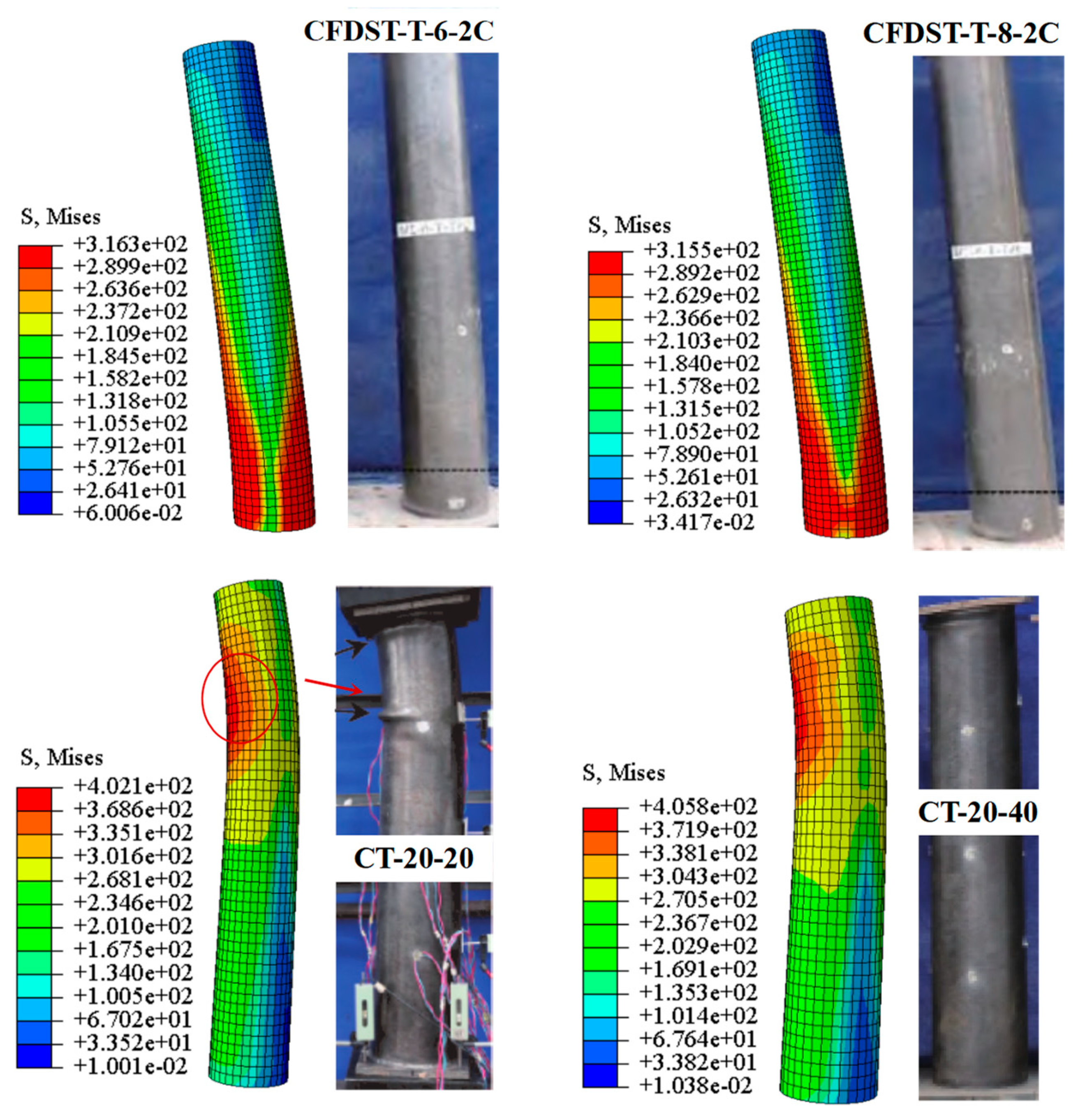
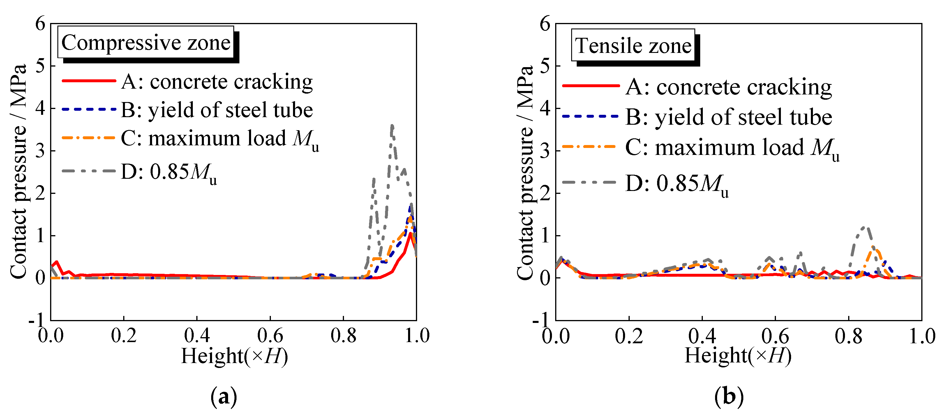
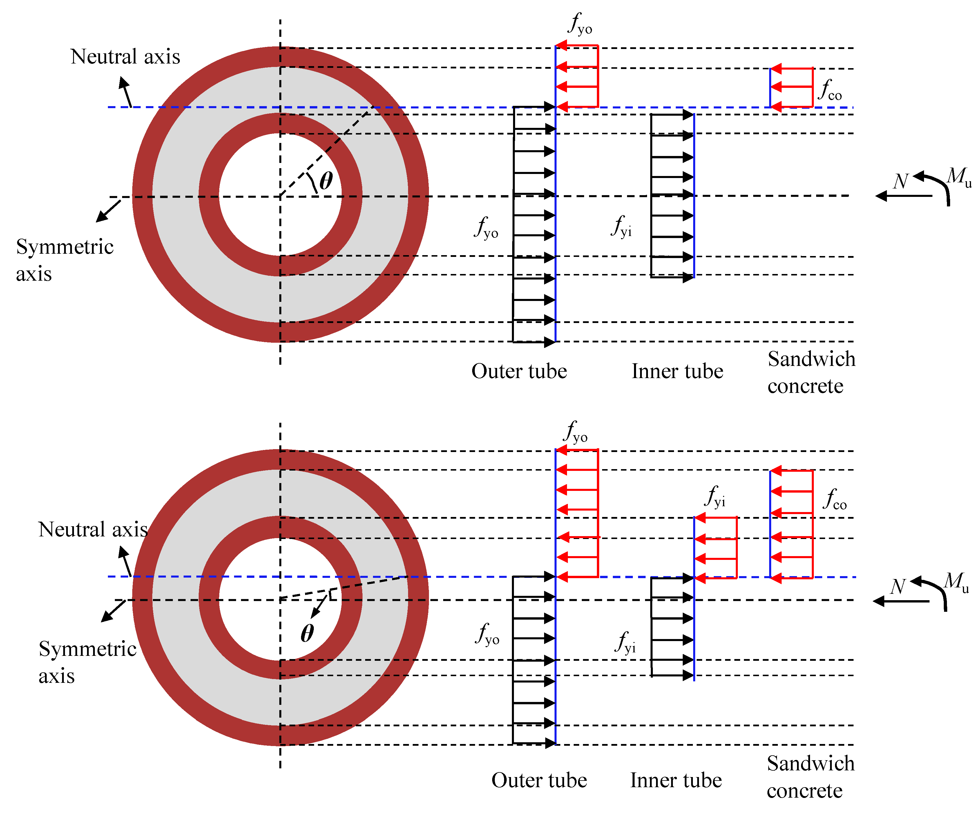
The developed FE models for tapered CFDST members are verified by the failure pattern and curves of load versus deformation. A systematic analysis of moment–deformation relationship, stress development, interaction pressure, and capacity contribution, is conducted to reveal the compressive–flexural mechanism, where the moment–deformation response can be featured by four typical points. The transverse local buckling of outer steel pipe partly weakens the distribution height of interface pressure in compression zone compared to that in tension zone; but sandwich concrete in compression zone obviously restricts the outer buckling of inner tube, therefore making a more compact interface contact than that in tension zone.
(2)
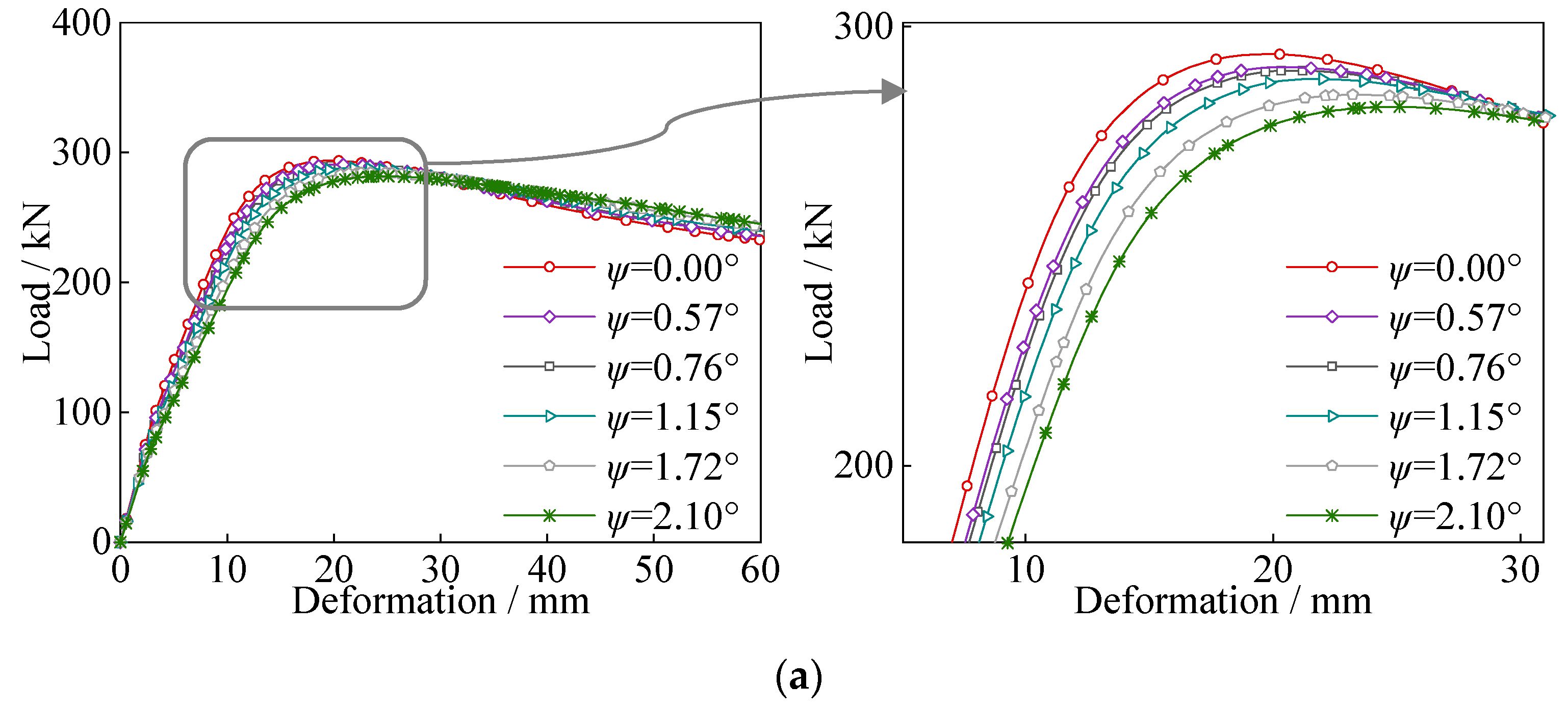
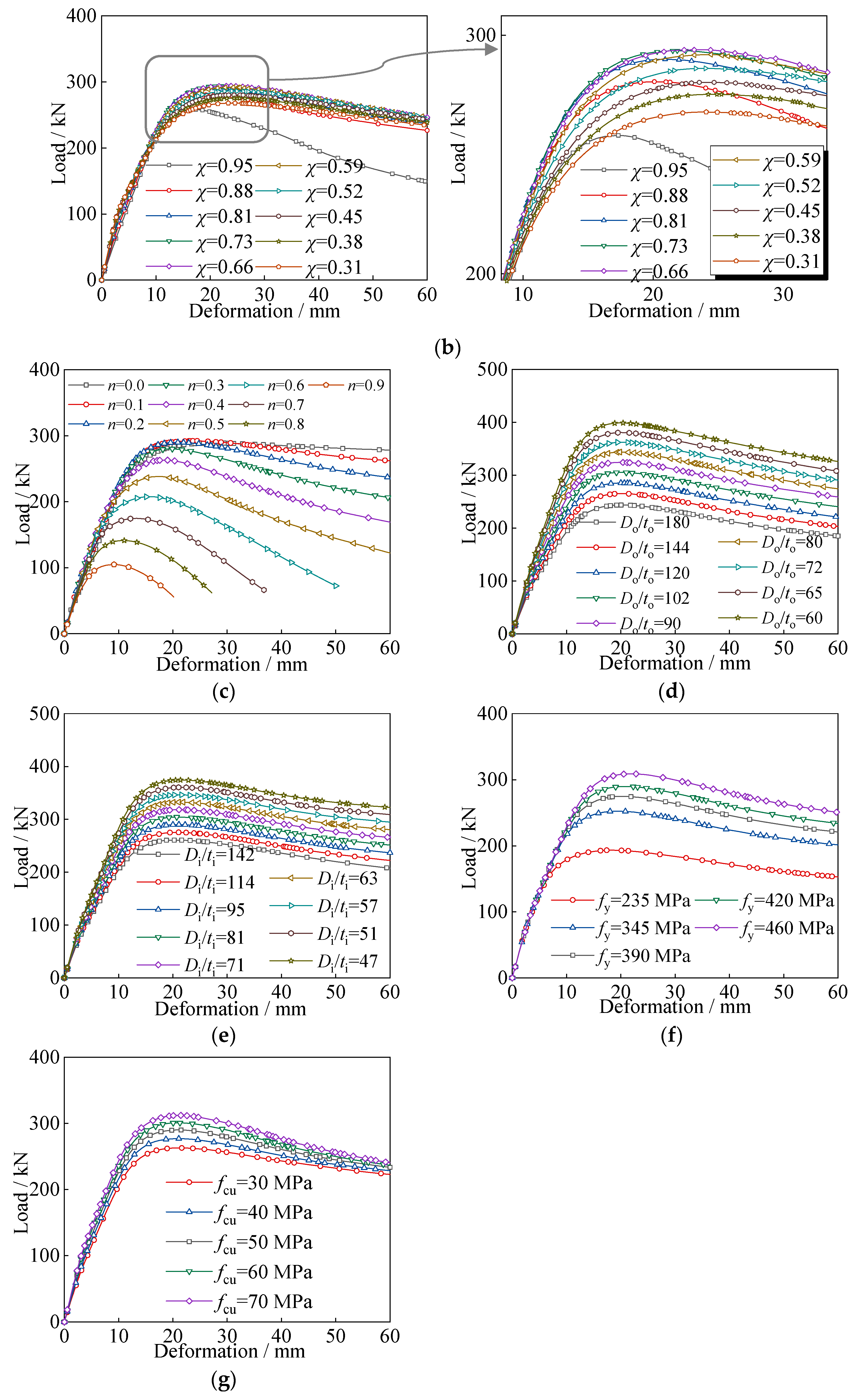
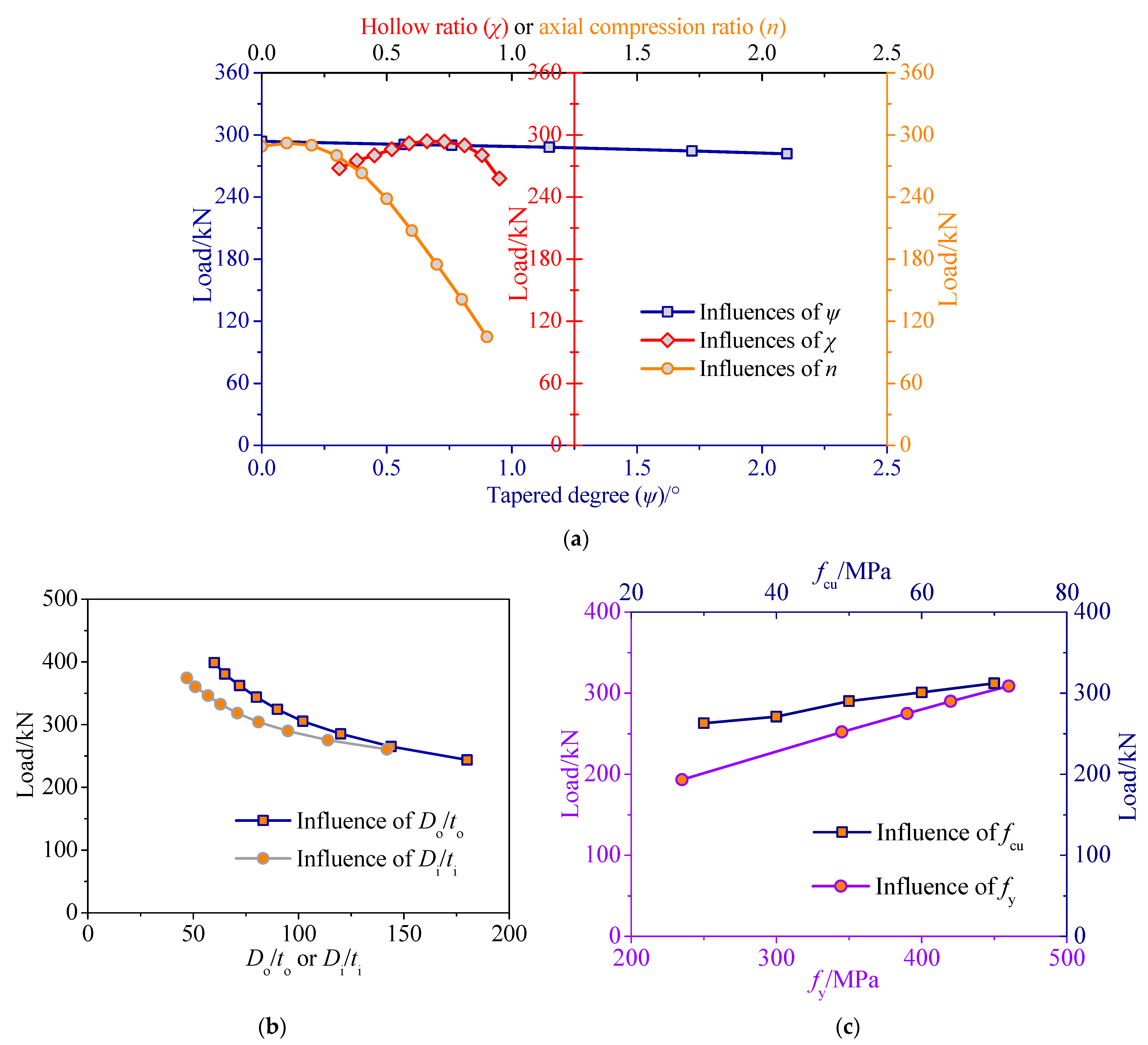
The parametric analysis is studied to reflect the actions of tapered angle (ψ), hollow ratio (χ), axial compression ratio (n), Do/to ratio, Di/ti ratio, yielding strength (fy) and compressive cubic concrete strength (fcu). Increasing tapered angle (ψ) slightly reduces the bearing capacity; appropriately enhancing hollow ratios based on the limitation of existing design code can also obtain reasonable compressive–flexural behavior; the higher axial compression level makes a remarkable impact on post-peak behavior and bearing strength; the influence of Do/to ratio is more significant than Di/ti ratio; the enhancement of strength (fy and fcu) produces an approximately linear increase trend on bearing capacity.
(3)
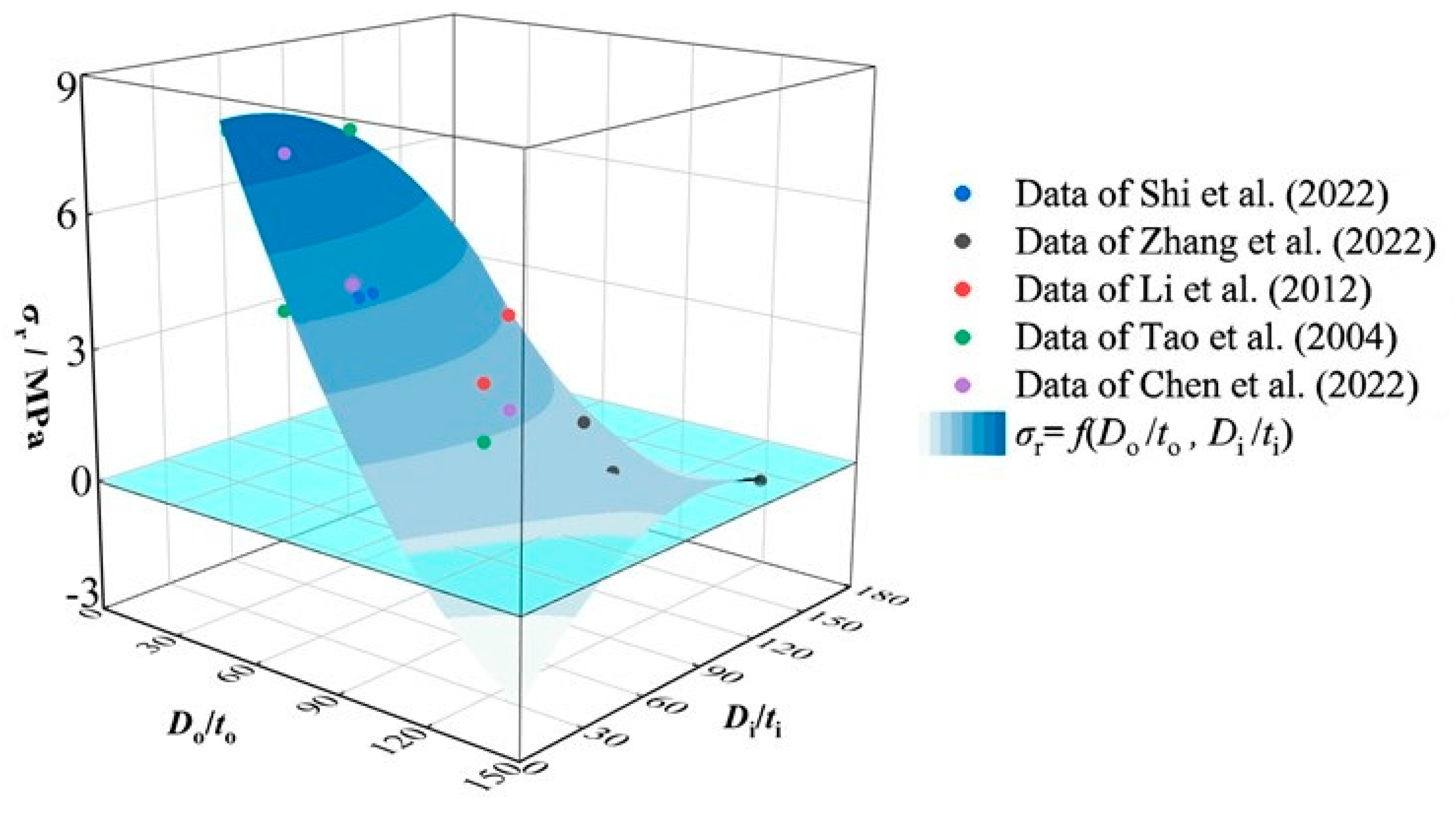
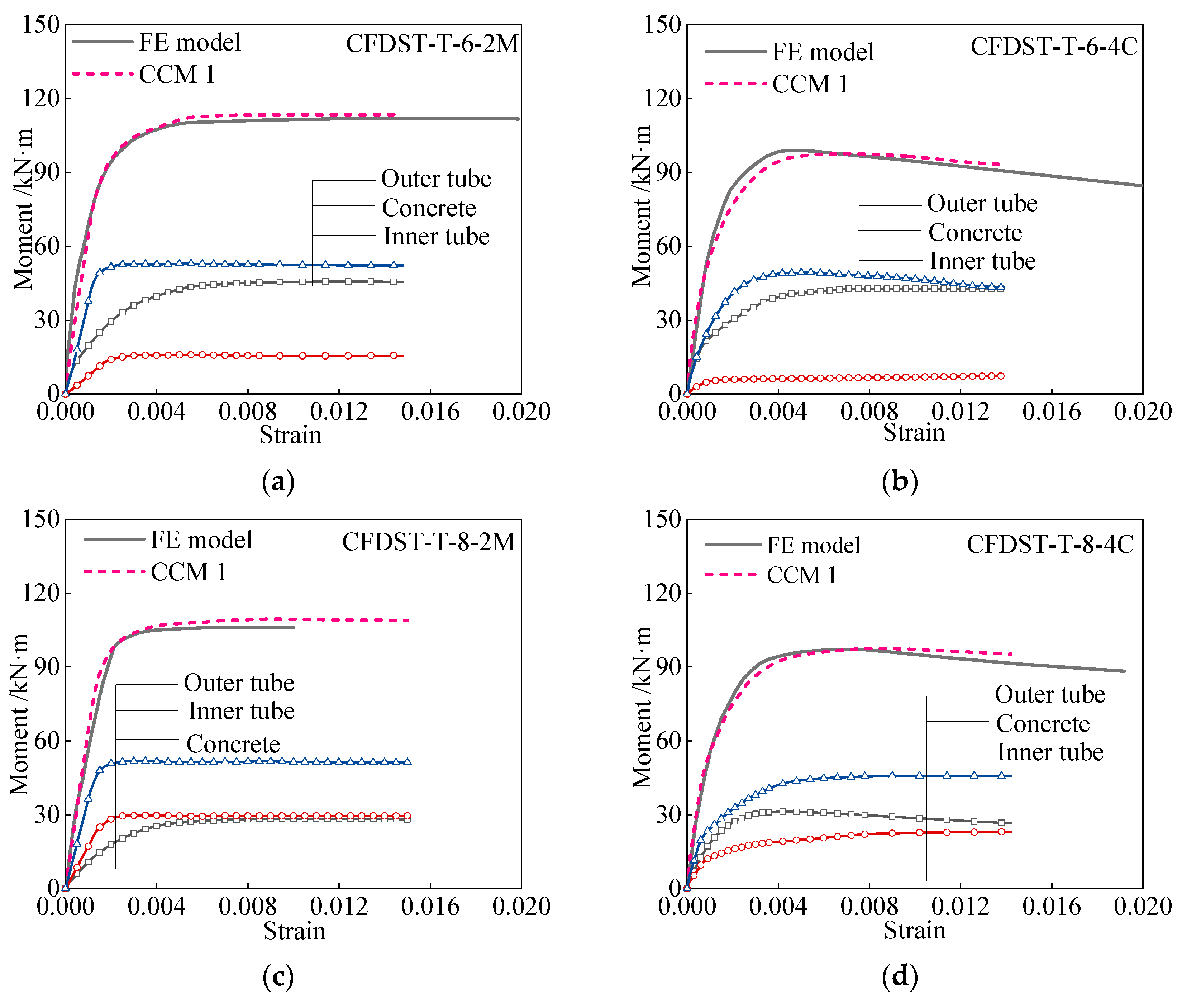
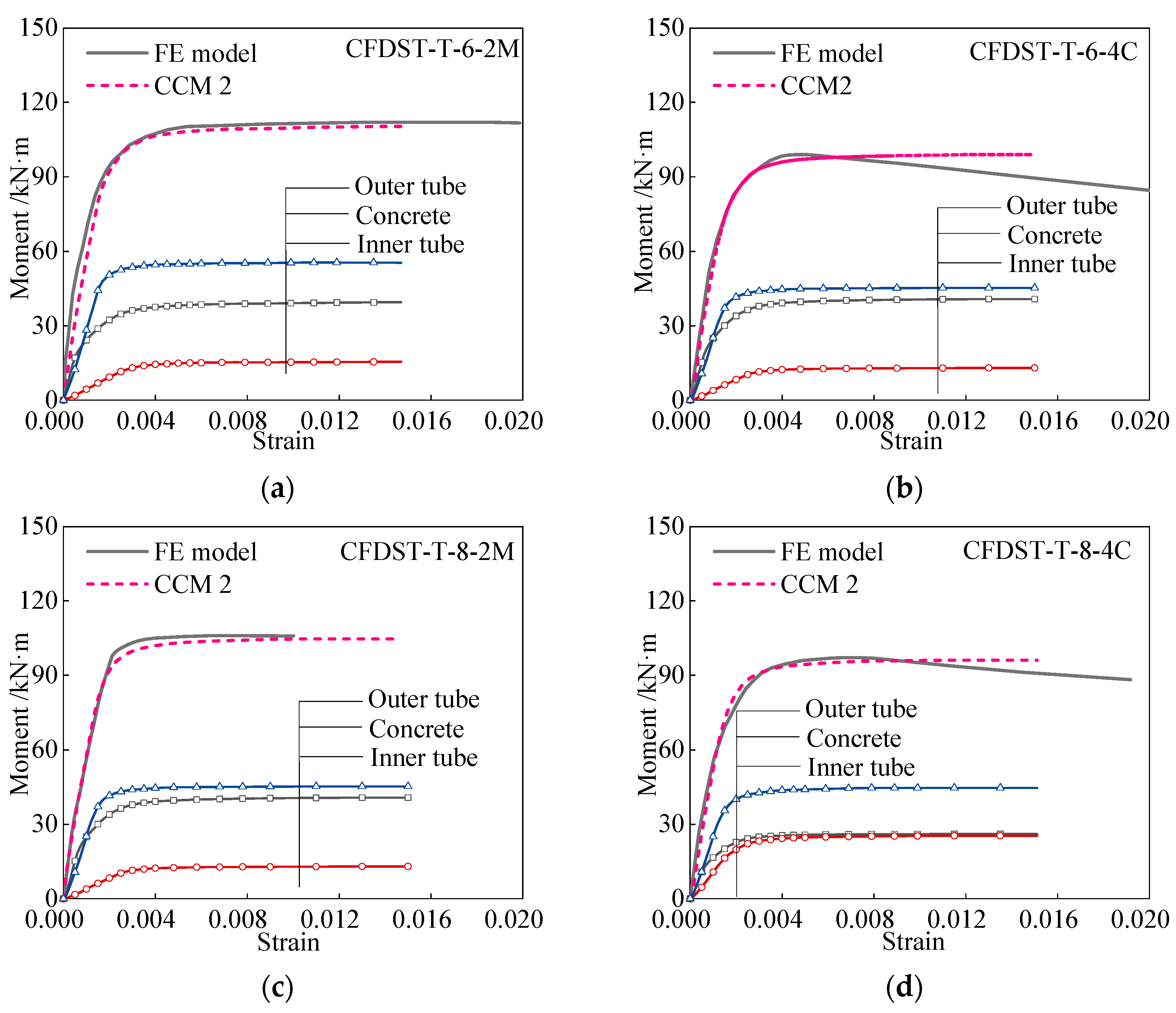
The modified CSI method is developed to calculate the moment–strain (M-ε) curves of tapered CFDST members, where a modified confined concrete model (CCM 2) with transverse confinement stress (σr) as explicit parameter is incorporated.
(4)
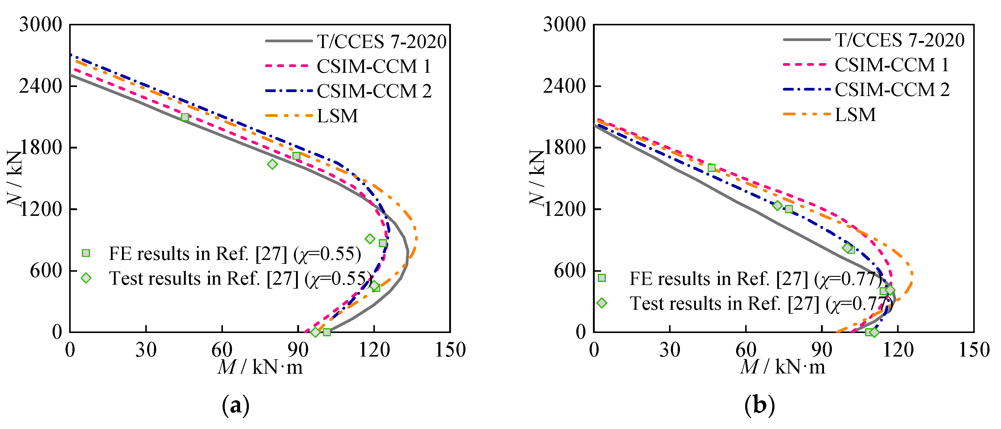
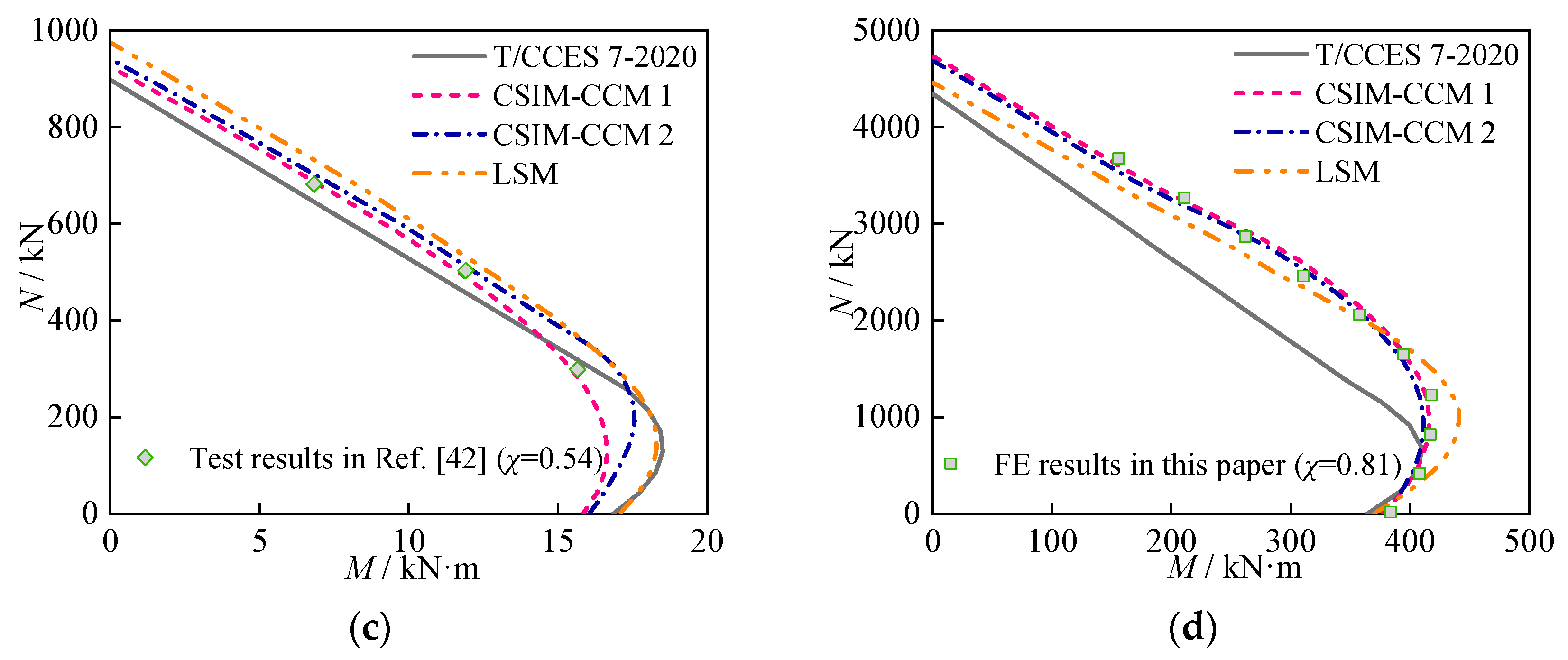
Design methods based on the modified CSI method and limit state method (LSM) are verified and suggested as a simplified design tool for calculating the N-M correlation curves, where the comparison result indicates that calculation result in design code T/CCES 7-2020 displays a more significant conservative forecast, especially for those CFDST members under the designed large hollow ratios.

Author Contributions

Conceptualization, J.-T.W. and X.-H.L.; methodology, J.-T.W.; validation, J.-T.W., X.-H.L. and Y.-W.L.; formal analysis, J.-T.W. and X.-H.L.; investigation, J.-T.W. and X.-H.L.; resources, J.-T.W.; writing—original draft preparation, J.-T.W. and X.-H.L.; writing—review and editing, J.-T.W., X.-H.L. and Y.-W.L.; visualization, J.-T.W. and X.-H.L.; supervision, J.-T.W. and Q.S.; project administration, J.-T.W. and Q.S.; funding acquisition, J.-T.W. and Q.S. All authors have read and agreed to the published version of the manuscript.

Funding

This research was funded by State Grid Zhejiang Electric Power Co., LTD., grant number 5211JY220003.

Institutional Review Board Statement

Not applicable.

Informed Consent Statement

Not applicable.

Data Availability Statement

The data presented in this study are available on request from the corresponding author.

Acknowledgments

The authors acknowledge the numerical assistance from the team members of Xi’an Jiaotong University and Xi’an University of Architecture and Technology.

Conflicts of Interest

The authors declare no conflict of interest.

Abbreviations

CFDST membersconcrete-filled double skin steel tubular members
CSIMcross-sectional stress integration method
LSMlimit state method
SCFDST structuresstraight CFDST structures
TCFDST memberstapered CFDST members
dydistance at the random height to neutral axis
fccompression strength of concrete cylinder
fcucubic concrete strength under compression
fyyielding strength of steel
fyoyielding strength of outer steel pipe
fyiyielding strength of inner steel pipe
nso,celement numbers of circumferential direction of outer tube
nso,relement numbers of radial direction of outer tube
nsi,celement numbers of circumferential direction of inner tube
nsi,relement numbers of radial direction of inner tube
ncon,celement numbers of circumferential direction of hollow concrete
ncon,relement numbers of radial direction of hollow concrete
Rimmean radius of inner steel pipe
Rommean radius of outer steel pipe
Riw and Rinrespectively the exterior radius and interior radius of inner steel pipe
Row and Ronrespectively the exterior radius and interior radius of outer steel pipe
ti or toinner/outer tube’s thickness
yso,I,jdistance of outer tube at ith element along circumference and jth element of radial direction to neutral axis
ysi,i,jdistance of inner tube at ith element along circumference and jth element of radial direction to neutral axis
ycon,i,jdistance of hollow concrete infill at ith element along circumference and jth element of radial direction to neutral axis
Aso,i,jarea of outer tube at ith element along circumference and jth element of radial direction
Aso,i,jarea of inner tube at ith element along circumference and jth element of radial direction
Acon,i,jarea of hollow concrete infill at ith element along circumference and jth element of radial direction
Deoequivalent diameter of outer pipe
Deiequivalent diameter of inner pipe
Dibinner tube’s diameter at member bottom
Ditinner tube’s diameter at member top
Doexternal diameter of outer pipe
Dobouter tube’s diameter at specimen base
Dotouter tube’s diameter at specimen top
Eselasticity modulus of steel
Fcoc, Fsoc and Fsicrespectively, the compressive load contributions of hollow concrete infill, outer pipe, and inner pipe
Fsot and Fsittensile load contributions of outer steel pipe and inner steel pipe, respectively
H i k vertical coordinate value of neutral axis
Mutotal moment-resisting capacity around symmetric axis
Mcoc, Msoc and Msicrespectively the moment elements of compressive areas of hollow concrete infill, outer pipe and inner pipe
Msot and Msitmoment capacities of tensile areas of outer and inner pipes
σrtransverse confinement stress
σpttensile strength of concrete
σso,i,jstress of outer tube at ith element along circumference and jth element of radial direction
σsi,i,jstress of inner tube at ith element along circumference and jth element of radial direction
σcon,i,jstress of hollow concrete at ith element along circumference and jth element of radial direction
εptpeak strain at tensile concrete strength
ε so i strain of outer pipe
ε si i strain of inner pipe
ε con i strain of hollow concrete infill
ψtapered angle
χhollow ratio

References

  1. Igwemezie, V.; Mehmanparast, A.; Kolios, A. Current trend in offshore wind energy sector and material requirements for fatigue resistance improvement in large wind turbine support structures–A review. Renew. Sust. Energ. Rev. 2019, 101, 181–196. [Google Scholar] [CrossRef]
  2. Jiang, Z. Installation of offshore wind turbines: A technical review. Renew. Sust. Energ. Rev. 2021, 139, 110576. [Google Scholar] [CrossRef]
  3. Kim, D.H.; Lee, S.G. Reliability analysis of offshore wind turbine support structures under extreme ocean environmental loads. Renew. Energ. 2015, 79, 161–166. [Google Scholar] [CrossRef]
  4. Nassiraei, H.; Zhu, L.; Gu, C. Static capacity of collar plate reinforced tubular X-connections subjected to compressive loading: Study of geometrical effects and parametric formulation. Ships Offshore Struct. 2021, 16, 54–69. [Google Scholar] [CrossRef]
  5. Nassiraei, H.; Mojtahedi, A.; Lotfollahi-Yaghin, M.A. Static strength of X-joints reinforced with collar plates subjected to brace tensile loading. Ocean Eng. 2018, 161, 227–241. [Google Scholar] [CrossRef]
  6. Moghaddam, B.T.; Hamedany, A.M.; Taylor, J.; Mehmanparast, A.; Brennan, F.; Davies, C.M.; Nikbin, K. Structural integrity assessment of floating offshore wind turbine support structures. Ocean Eng. 2020, 208, 107487. [Google Scholar] [CrossRef]
  7. Ma, Z.; Li, W.; Ren, N.; Ou, J. The typhoon effect on the aerodynamic performance of a floating offshore wind turbine. J. Ocean Eng. Sci. 2017, 2, 279–287. [Google Scholar] [CrossRef]
  8. Yeter, B.; Garbatov, Y.; Soares, C.G. Uncertainty analysis of soil-pile interactions of monopile offshore wind turbine support structures. Appl. Ocean Res. 2019, 82, 74–88. [Google Scholar] [CrossRef]
  9. Ju, S.H.; Huang, Y.C. Analyses of offshore wind turbine structures with soil-structure interaction under earthquakes. Ocean Eng. 2019, 187, 106190. [Google Scholar] [CrossRef]
  10. Díaz, H.; Soares, C.G. Review of the current status, technology and future trends of offshore wind farms. Ocean Eng. 2020, 209, 107381. [Google Scholar] [CrossRef]
  11. Zhao, X.L.; Tong, L.W.; Wang, X.Y. CFDST stub columns subjected to large deformation axial loading. Eng. Struct. 2010, 32, 692–703. [Google Scholar] [CrossRef]
  12. Li, W.; Han, L.H.; Chan, T.M. Tensile behaviour of concrete-filled double-skin steel tubular members. J. Constr. Steel Res. 2014, 99, 35–46. [Google Scholar] [CrossRef]
  13. Li, W.; Han, L.H.; Chan, T.M. Numerical investigation on the performance of concrete-filled double-skin steel tubular members under tension. Thin Wall. Struct. 2014, 79, 108–118. [Google Scholar] [CrossRef]
  14. Shi, Y.L.; Ji, S.H.; Wang, W.D.; Xian, W.; Fan, J.H. Axial compressive behaviour of tapered CFDST stub columns with large void ratio. J. Constr. Steel Res. 2022, 191, 107206. [Google Scholar] [CrossRef]
  15. Deng, R.; Zhou, X.H.; Deng, X.W.; Ke, K.; Bai, J.L.; Wang, Y.H. Compressive behaviour of tapered concrete-filled double skin steel tubular stub columns. J. Constr. Steel Res. 2021, 184, 106771. [Google Scholar] [CrossRef]
  16. Zhang, D.; Li, W.; Fu, K.; Li, T.; Deng, R.; Wang, Y. Ultimate compressive capacity of tapered concrete-filled double skin steel tubular stub columns with large hollow ratio. J. Constr. Steel Res. 2022, 196, 107356. [Google Scholar] [CrossRef]
  17. Vernardos, S.; Gantes, C. Experimental behavior of concrete-filled double-skin steel tubular (CFDST) stub members under axial compression: A comparative review. Structures 2019, 22, 383–404. [Google Scholar] [CrossRef]
  18. Fang, Y.; Wang, Y.; Hou, C.; Lu, B. CFDST stub columns with galvanized corrugated steel tubes: Concept and axial behaviour. Thin Wall. Struct. 2020, 157, 107116. [Google Scholar] [CrossRef]
  19. Li, W.; Ren, Q.X.; Han, L.H.; Zhao, X.L. Behaviour of tapered concrete-filled double skin steel tubular (CFDST) stub columns. Thin Wall. Struct. 2012, 57, 37–48. [Google Scholar] [CrossRef]
  20. Zhang, Y.B.; Han, L.H.; Li, W. Analytical behaviour of tapered CFDST stub columns under axially partial compression. J. Constr. Steel Res. 2017, 139, 302–314. [Google Scholar] [CrossRef]
  21. Jin, K.Y.; Zhou, X.H.; Wen, H.; Deng, R.; Li, R.F.; Wang, Y.H. Compressive behaviour of stiffened thin-walled CFDST columns with large hollow ratio. J. Constr. Steel Res. 2023, 205, 107886. [Google Scholar] [CrossRef]
  22. Deng, R.; Zhou, X.H.; Wen, H.; Li, R.F.; Ji, W.D.; Wang, Y.H.; Ren, W. Torsional behaviour of tapered concrete-filled double-skin steel tubular columns with large hollow ratios. Thin Wall. Struct. 2023, 183, 110343. [Google Scholar] [CrossRef]
  23. Wang, W.D.; Fan, J.H.; Shi, Y.L.; Xian, W. Research on mechanical behaviour of tapered concrete-filled double skin steel tubular members with large hollow ratio subjected to bending. J. Constr. Steel Res. 2021, 182, 106689. [Google Scholar] [CrossRef]
  24. Liu, H.; Shi, Y.L.; Fan, J.H.; Wang, W.D. Research on the mechanical properties of tapered concrete-filled double skin steel tubular members subjected to pure bending load. Prog. Steel Build. Struct. 2021, 23, 9–17. (In Chinese) [Google Scholar]
  25. Wang, X.T.; Peng, X.; Zhang, J.P.; Yan, C.Z.; Li, X.G.; Yan, F.J. An experimental study on the flexural behavior of tapered high-strength thin-walled concrete-filled double skin steel tubular members. Prog. Steel Build. Struct. 2022, 24, 24–33. (In Chinese) [Google Scholar]
  26. Li, W.; Han, L.H.; Ren, Q.X.; Zhao, X.L. Behavior and calculation of tapered CFDST columns under eccentric compression. J. Constr. Steel Res. 2013, 83, 127–136. [Google Scholar] [CrossRef]
  27. Han, Y.; Wang, W.D. Research on tapered concrete-filled double skin steel tubular members subjected to shear and axial compression. Prog. Steel Build. Struct. 2021, 23, 23–32. (In Chinese) [Google Scholar]
  28. Shi, Y.L.; Zhang, C.F.; Xian, W.; Wang, W.D. Research on mechanical behavior of tapered concrete-filled double skin steel tubular members under eccentric compression. J. Build. Struct. 2021, 42, 155–164. (In Chinese) [Google Scholar]
  29. Shi, Y.L.; Ji, S.H.; Wang, W.D.; Zhang, C.; Fan, J.H. Study on hysteretic behavior of tapered concrete-filled double skin steel tubular beam-columns with large hollow ratio. China Civil Eng. J. 2022, 35, 75–88. (In Chinese) [Google Scholar]
  30. Skalomenos, K.A.; Hayashi, K.; Nishi, R.; Inamasu, H.; Nakashima, M. Experimental behavior of concrete-filled steel tube columns using ultrahigh-strength steel. J. Struct. Eng. 2016, 142, 04016057. [Google Scholar] [CrossRef]
  31. Wang, J.; Sun, Q.; Li, J. Experimental study on seismic behavior of high-strength circular concrete-filled thin-walled steel tubular columns. Eng. Struct. 2019, 182, 403–415. [Google Scholar] [CrossRef]
  32. Fan, J.H.; Wang, W.D.; Shi, Y.L.; Ji, S.H. Torsional behaviour of tapered CFDST members with large void ratio. J. Build. Eng. 2022, 52, 104434. [Google Scholar] [CrossRef]
  33. Lin, L.; Wang, F.C. Investigation of analytical behavior of concrete filled steel tubular (CFST) offshore rock-socketed pile under lateral load. Ocean Eng. 2023, 277, 114279. [Google Scholar] [CrossRef]
  34. Li, W.; Li, W.J.; Xu, L.F.; Wang, F.C. Performance of CFDST beams using high-strength steel under bending. Struct. 2021, 34, 2644–2655. [Google Scholar] [CrossRef]
  35. Wang, F.C.; Han, L.H. Analytical behavior of carbon steel-concrete-stainless steel double-skin tube (DST) used in submarine pipeline structure. Mar. Struct. 2019, 63, 99–116. [Google Scholar] [CrossRef]
  36. Wang, F.C.; Zhao, H.Y.; Han, L.H. Analytical behavior of concrete-filled aluminum tubular stub columns under axial compression. Thin Wall. Struct. 2019, 140, 21–30. [Google Scholar] [CrossRef]
  37. Shen, J.M.; Wang, C.Z.; Jiang, J.J. Finite Element Method of Reinforced Concrete and Limit Analysis of Plate and Shell; Tsinghua University Press: Beijing, China, 1993. (In Chinese) [Google Scholar]
  38. Yu, M.H.; Ma, G.W.; Li, J.C. Structural Plasticity; Zhejiang University Press: Hangzhou, China, 2009. [Google Scholar]
  39. Han, L.H. Concrete Filled Steel Tubular Structures—Theory and Practice; Science Press: Beijing, China, 2016. (In Chinese) [Google Scholar]
  40. Chen, Y.Y.; Ning, J.H.; Zhang, Y.X.; Liu, S.W.; Li, X.Y. Load bearing capacity calculation method of circular concrete-filled double skin steel tubular stub columns. Prog. Steel Build. Struct. 2021, 23, 85–93. (In Chinese) [Google Scholar]
  41. The European Committee for Standardization. Eurocode 4: Design of Composite Steel and Concrete Structures—Part 1-1: General Rules and Rules for Buildings; British Standards Institution: London, UK, 2004. [Google Scholar]
  42. Tao, Z.; Han, L.H.; Zhao, X.L. Behaviour of concrete-filled double skin (CHS inner and CHS outer) steel tubular stub columns and beam-columns. J. Constr. Steel Res. 2004, 60, 1129–1158. [Google Scholar] [CrossRef]
  43. Chen, Q.S.; Pang, Y.H.; Kong, L.; Li, B.F.; An, N.; Wang, X.T. Experimental study on high strength tapered thin walled concrete-filled double skin steel tubular stub columns under axial compression. J. Xi’an Univ. Arch. Tech. (Nat. Sci. Ed.) 2022, 54, 306–316. (In Chinese) [Google Scholar]
  44. Zheng, Y.; Wang, C.; Chen, M. Flexural strength and stiffness of circular double-skin and double-tube concrete-filled steel tubes. Mar. Struct. 2022, 81, 103126. [Google Scholar] [CrossRef]
  45. Yu, M.; Pei, X.; Xu, L.; Ye, J. A unified formula for calculating bending capacity of solid and hollow concrete-filled steel tubes under normal and elevated temperature. J. Constr. Steel Res. 2018, 141, 216–225. [Google Scholar] [CrossRef]
Figure 1. Engineering utilization of support structures of tapered CFDST members. The arrows are to reflect the contact pressures of double-skin tubes to sandwich concrete.
Jmse 11 01621 g001
Figure 2. Stress–strain curves for steel tubes.
Jmse 11 01621 g002
Figure 3. Establishment of numerical model.
Jmse 11 01621 g003
Figure 4. Model validation by failure pattern [28,29].
Jmse 11 01621 g004
Figure 5. Verification by load–displacement curves. (a) Comparison on test result in Ref. [29]; (b) comparison on test result in Ref. [28].
Jmse 11 01621 g005aJmse 11 01621 g005b
Figure 6. Analysis of moment–displacement curves.
Jmse 11 01621 g006
Figure 7. Development of normal stress.
Jmse 11 01621 g007
Figure 8. Constraint action of outer tube versus sandwich concrete. (a) Confinement action in compressive zone; (b) confinement action in tensile zone.
Jmse 11 01621 g008
Figure 9. Constraint action of inner tube versus sandwich concrete. (a) Confinement action in compressive zone; (b) confinement action in tensile zone.
Jmse 11 01621 g009
Figure 10. Definition on height value.
Jmse 11 01621 g010
Figure 11. Influence on lateral load–displacement curve. (a) Influence of ψ; (b) influence of χ; (c) influence of n; (d) Influence of Do/to ratio; (e) influence of Di/ti ratio; (f) influence of fy; (g) influence of fcu.
Jmse 11 01621 g011aJmse 11 01621 g011b
Figure 12. Influence on carrying capacity. (a) Influence of ψ, χ, and n; (b) influence of D/t ratios; (c) Influence of fy and fcu.
Jmse 11 01621 g012
Figure 13. Schematic diagram of modified cross-sectional stress integration method.
Jmse 11 01621 g013
Figure 14. 3D surface of transverse confinement stress [14,16,19,42,43].
Jmse 11 01621 g014
Figure 15. Calculation procedure.
Jmse 11 01621 g015
Figure 16. Verification of modified CSI method based on concrete model CCM 1. (a) CFDST-T-6-2M; (b) CFDST-T-6-4C; (c) CFDST-T-8-2M; (d) CFDST-T-8-4C.
Jmse 11 01621 g016
Figure 17. Verification of modified CSI method based on concrete model CCM 2. (a) CFDST-T-6-2M; (b) CFDST-T-6-4C; (c) CFDST-T-8-2M; (d) CFDST-T-8-4C.
Jmse 11 01621 g017
Figure 18. Stress distribution at ultimate limit state.
Jmse 11 01621 g018
Figure 19. Verification of proposed methods on predicting N-M correlation curves. (a) Verification 1; (b) verification 2; (c) verification 3; (d) verification 4.
Jmse 11 01621 g019aJmse 11 01621 g019b
Disclaimer/Publisher’s Note: The statements, opinions and data contained in all publications are solely those of the individual author(s) and contributor(s) and not of MDPI and/or the editor(s). MDPI and/or the editor(s) disclaim responsibility for any injury to people or property resulting from any ideas, methods, instructions or products referred to in the content.

