Article

Simulation of a Ship’s Block Panel Assembly Process: Optimizing Production Processes and Costs through Welding Robots

1
Department of Naval Architecture, Ocean and Marine Engineering, University of Strathclyde, 100 Montrose Street, Glasgow G4 0LZ, UK
2
Department of Naval Architecture, Sepuluh Nopember Institute of Technology, Surabaya 60111, Indonesia
*
Author to whom correspondence should be addressed.
J. Mar. Sci. Eng. 2023, 11(8), 1506; https://doi.org/10.3390/jmse11081506
Submission received: 4 July 2023 / Revised: 24 July 2023 / Accepted: 26 July 2023 / Published: 29 July 2023
(This article belongs to the Special Issue Advances in Marine Structures)

Abstract

:
Conventional welding techniques for complex structures often rely on human involvement, which can be prone to errors when deviations from the planned process occur. In contrast, robotic welding is highly precise and effective, particularly in the assembly of complex structures such as double-bottom ships. Therefore, this paper presents a comprehensive technical and economic analysis comparing robotic welding to conventional welding in the assembly process of a ship’s block panels. The study aims to evaluate and compare the strategies employed in robotic welding and conventional welding, with a specific focus on the ship double-bottom context. Furthermore, an economic value analysis is conducted to assess the cost effectiveness of each approach. The analysis reveals that robotic welding can achieve a significantly faster welding speed, completing the process approximately 3.85 times quicker compared to conventional methods. Moreover, the ratio of electricity and man-hours between robot welding and conventional welding is 1:2.75. These findings highlight the potential for cost savings by implementing robotic welding processes. The analysis reveals a significant difference in operational costs, highlighting the efficiency and cost effectiveness of robotic welding compared to conventional methods.

1. Introduction

In modern industry, robots have become widely used in factories, where they have taken over many tasks that were once performed by humans. For example, robots have become the prime movers in the automotive, electronic device, and computer device industries. Robots are used because they are accurate, efficient, and cost-effective. Robots can perform tasks quickly and accurately, and they can do so without getting tired or making mistakes. This can help to improve productivity and save money. In an effort to expand manufacturing capacity, researchers have been studying automated (robot-based) production. This research has led to the development of new technologies, such as innovative product design using topology optimization and additive manufacturing [1], a transportable robotic system for ship structures [2], and an intelligent inspection robot for dangerous and inaccessible sites [3]. Robotic automation has become increasingly common in the Japanese shipbuilding industry, in response to changes such as a decrease in the labor force and wage hikes. This is especially true for arc welding [4]. Some research has been conducted on the use of robots in welding applications. For example, one study found that welding process variables affect the quality of robotic MIG welding of EN24T steel [5]. Another study developed a robotic seam-tracking system using conditional generative adversarial networks and laser vision (CGAN) [6]. Other study of robot welding application was of a robot-assisted MIG/MAG welding system called “MyWelder” which was proposed as an excellent productive, intuitive, and easily customizable technology [7]. In addition, research has been conducted on the design of fully automated fabrication facilities for the shipbuilding sector. One study provided a layout for an automated fabrication workshop [8]. The workshop includes work areas for cutting, rolling, line heating, and loading of products, as well as for registering material plates. Therefore, it is important to analyze the current state of robotic welding technology in ship production technology.
The shipbuilding industry plays a pivotal role in constructing vessels that navigate our seas, and welding is a critical process within this industry. Welding is essential for joining structural components, ensuring the integrity and strength of the ships. The shipbuilding industry faces challenges in achieving efficient and high-quality welding processes. Conventional welding techniques are labor-intensive, prone to human error, and may have limitations in terms of productivity and quality control. On the other hand, robotic welding offers potential solutions by leveraging automation, precision, and consistency in the welding process. Robotic welding systems have the capability to improve productivity, reduce labor costs, and enhance weld quality in shipbuilding applications. However, implementing robotic welding in shipbuilding requires addressing challenges related to the initial investment, programming, flexibility, and maintenance. Addressing these challenges is crucial for enhancing efficiency, weld quality, and cost effectiveness in the shipbuilding industry [9].
In this case, robotic technology can be used to maximize welding work in difficult positions, such as joints in double-bottom construction. From an economic point of view, although the required initial investment is high, robotic welding can be used sustainably over time. Therefore, it is important to compare robotic welding with conventional welding. This article compares robotic welding and conventional welding from technical and financial perspectives, using a complex structure such as a double bottom as an example. The technical aspect of the comparison is related to the time it takes for a welding robot to join a double-bottom structure [10], which is then compared to the time it takes for this using conventional welding. In addition, the economic aspect of the comparison is related to the costs of operation and labor for robotic welding and conventional welding.
A large amount of research has been conducted on the use of robotic welding technology in the manufacturing industry. Some of the most notable studies include those by Zhang et al. [11], Feng et al. [12], Chen [13], Shapovalov et al. [14], and Jr et al. [15]. Other studies have focused on the use of robot welding in shipyards. For example, Feng et al. [16], Rooks [17], Kim et al. [18], and Olschok et al. [19] have all published research on this topic. However, there is no comparison between robotic welding and conventional welding in terms of technical and economic aspects available in the literature. This study focuses on comparing robotic welding and conventional welding in the case of assembling complex ship structures, such as double-bottom structures. This is undertaken by applying the optimal means of assembling complex ship structures [10].
The technical and economic aspects of shipbuilding are increasingly intertwined, with the optimization of the production process and reduction in costs being critical factors in maintaining competitiveness in the industry [20,21,22,23,24,25]. In this study, the use of robotic welding for a ship’s double-bottom assembly was simulated and analyzed in terms of both technical and economic performance. The goal was to identify opportunities for process optimization and cost reduction.

2. Methods

In this paper, a comparison is made between robotic welding and conventional welding in the assembly of a ship’s block panels. The simulation focuses on a ship’s double-bottom structures, which are explained in the following section.

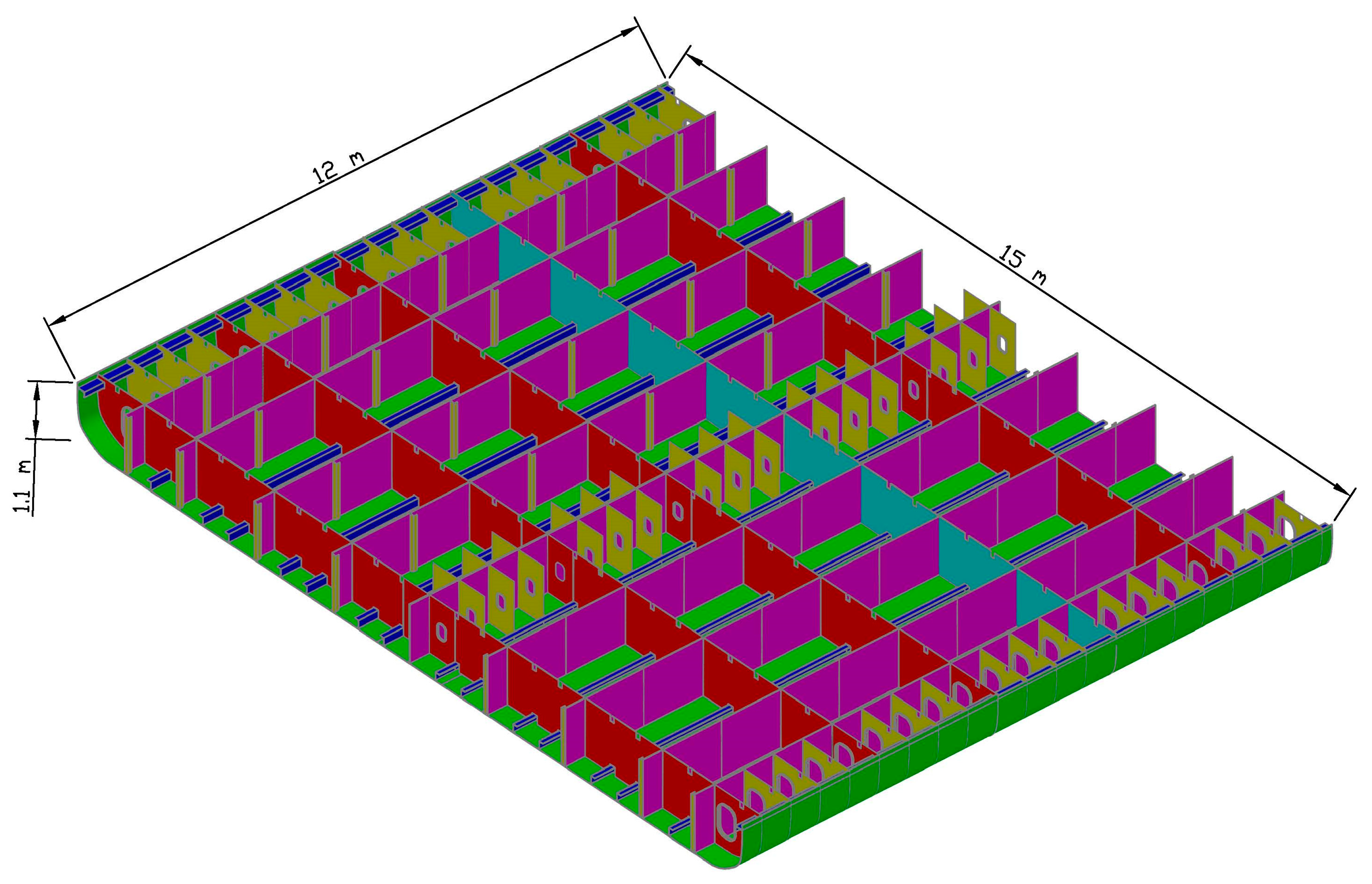
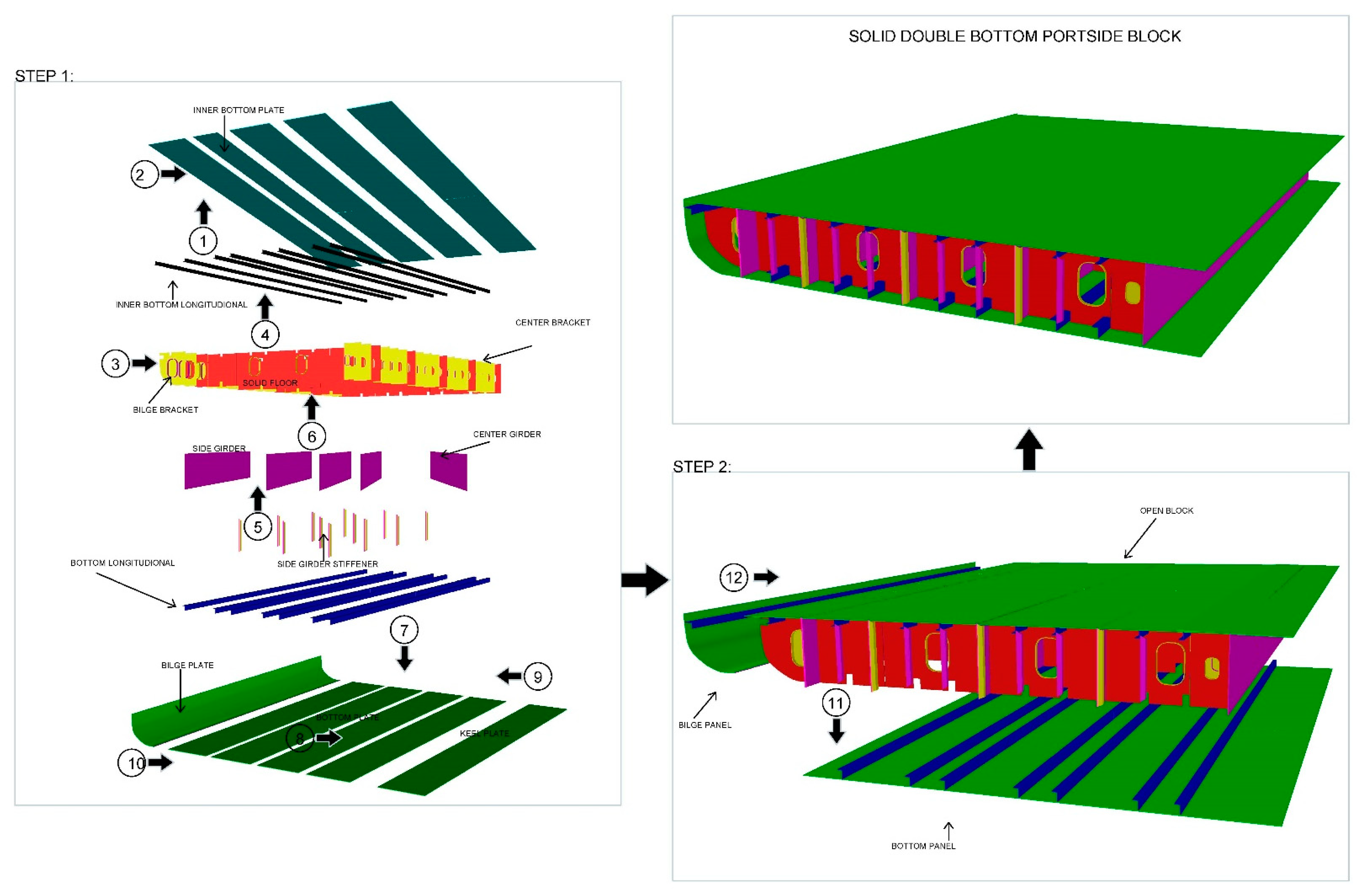
2.1. Ship’s Double-Bottom Construction

The double-bottom structure of the ship, as depicted in Figure 1, is one of its most crucial components. It is designed to withstand the hydrostatic forces that act on the bottom of the hull, as well as the weight of the freight.
The ship’s hull is essentially formed of bent plates that are joined by welding. If these plates are not stiffened, the bending moments caused by the loads may lead to more stress than the amount of stress that the material can withstand, which can then lead to failure. Stiffeners make the plates stiffer, which helps to prevent failure (or increases their section modulus).
The shipbuilding process has two phases: design and construction. The design phase involves converting the owner’s requirements into a ship design that can be used to build the ship. The ship’s double bottom is built by assembling individual parts into panels, blocks, and then the entire structure, as shown in Figure 2 [26]. The process of assembling a hull structure is similar to the process of assembling other floating structures, such as a floating dock [27]. The sub-assembly stage involves joining the parts that were fabricated in the previous stage. A component block is created by combining the products of the cutting and shaping conducted by the fabrication workshop, including brackets, plate flooring, and face plates. At this stage, fitting, welding, and grinding are all part of the process.
Welding procedures utilizing the unit panel method are commonly employed in the construction of large ships, as this approach offers improved work efficiency compared to traditional methods. In this method, panels with longitudinal stiffeners are first prepared and welded to the skin material through submerged arc welding [28]. The assembly process consists of several steps, as shown in Figure 2.
Initially, a bottom plate that has precisely the same form as that of the top plate is fabricated. Afterward, various transverse web floors and girders are joined onto the inner bottom plate. In the second step, the prepared unit panels, with longitudinal stiffeners, are placed on the open block in their correct locations [10]. Finally, the unit panels are welded to the open block along the stiffeners, ensuring a secure fit.
After the unit panels are welded to the open block, the solid block is welded. The welding must be carried out from inside the solid block, along the edges where the inner bottom panel and the bottom panel meet. The unit panel method makes the construction process more efficient, especially for large ships.

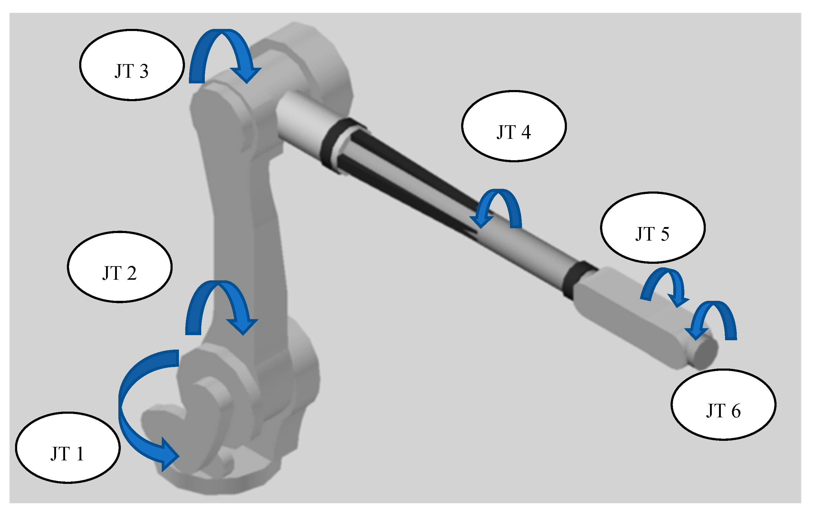
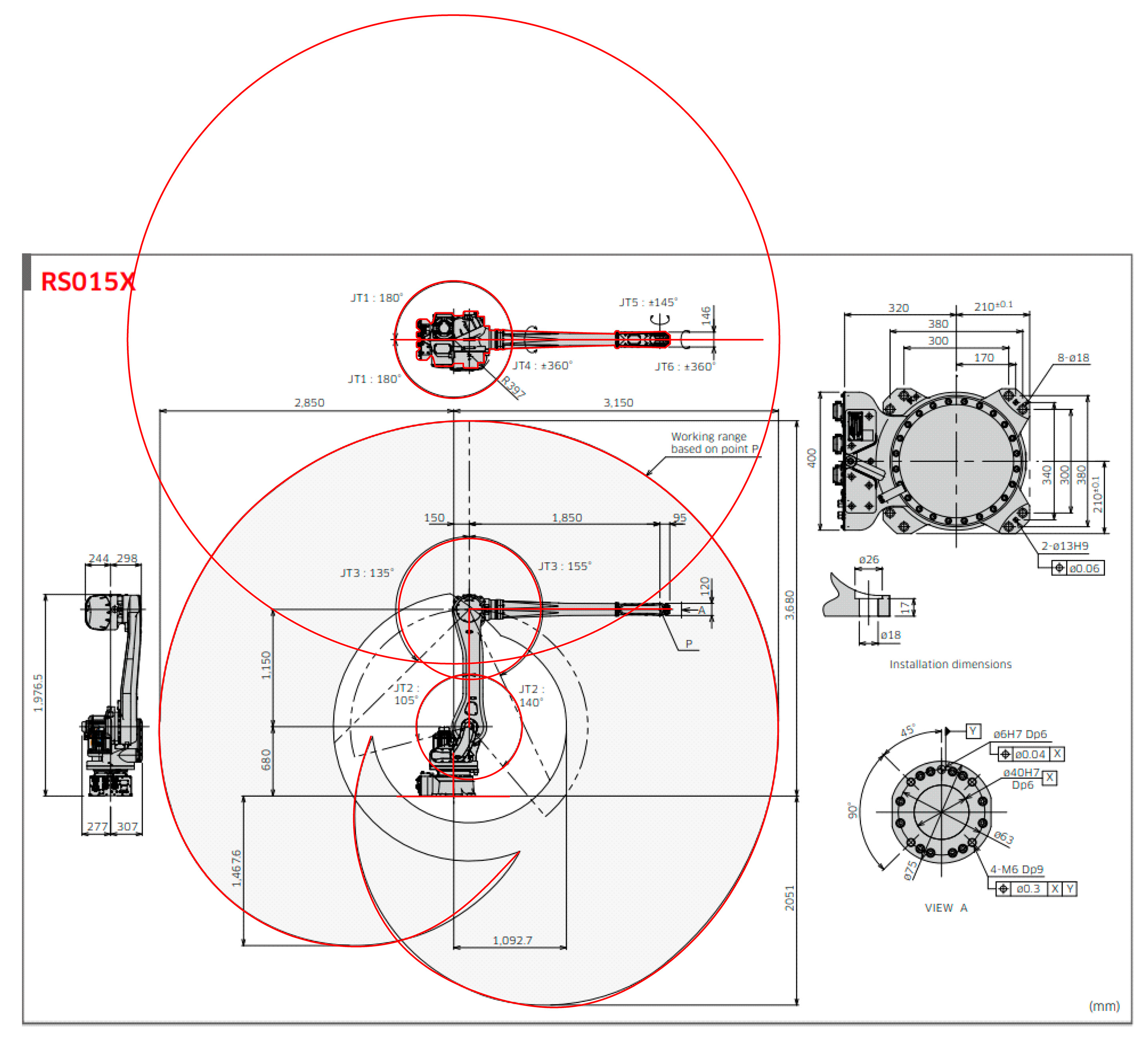
2.2. Robotic Welding Specifications Used for Simulation

Robotic welding has become an increasingly popular technology in manufacturing and production processes due to its ability to increase productivity, quality, and efficiency while reducing costs [4]. Robotic welding is particularly effective for repetitive welding of parts with similar structures and simple parts with high volume, and joining piece parts that require a high degree of physical effort from welders. Furthermore, it is well-suited to welding common structures or standard parts that are used in many different ships, making it a cost-effective solution for shipbuilding.
In the production of a double-bottom ship, a robotic welding machine must be able to move in various directions to reach all necessary welding points. Therefore, the robot arm specifications used must have six degrees of freedom, as shown in Figure 3. In this simulation, the specifications of the Kawasaki RS015X robot arm are utilized to analyze the welding reach for panel assembly. The robot’s six degrees of freedom allow it to move in a variety of ways, including arm rotation, arm out–in, arm up–down, wrist swivel, wrist bend, and wrist twist, providing the necessary flexibility and precision to perform a wide range of welding tasks. The high level of precision and accuracy provided by the robot’s six axes of movement make it well-suited for tasks that require a high degree of accuracy and repeatability [28].
The robot has six axes of movement, each of which has a wide range of motion and high speeds, as shown in Figure 4. On the first axis, known as arm rotation (JT 1), the robot can rotate up to ±180 degrees and move at a speed of 180 degrees per second. On the second axis, arm out-in (JT 2), the robot has a range of +140 degrees to −105 degrees and a speed of 180 degrees per second. The third axis, arm up-down (JT 3), has a range of +135 degrees to −155 degrees and a speed of 200 degrees per second. On the fourth axis, wrist swivel (JT 4), the robot can swivel up to ±360 degrees and move at a speed of 410 degrees per second. On the fifth axis, wrist bend (JT 5), the robot has a range of ±145 degrees and a speed of 360 degrees per second. On the sixth and final axis, wrist twist (JT 6), the robot can twist up to ±360 degrees and move at a speed of 610 degrees per second.

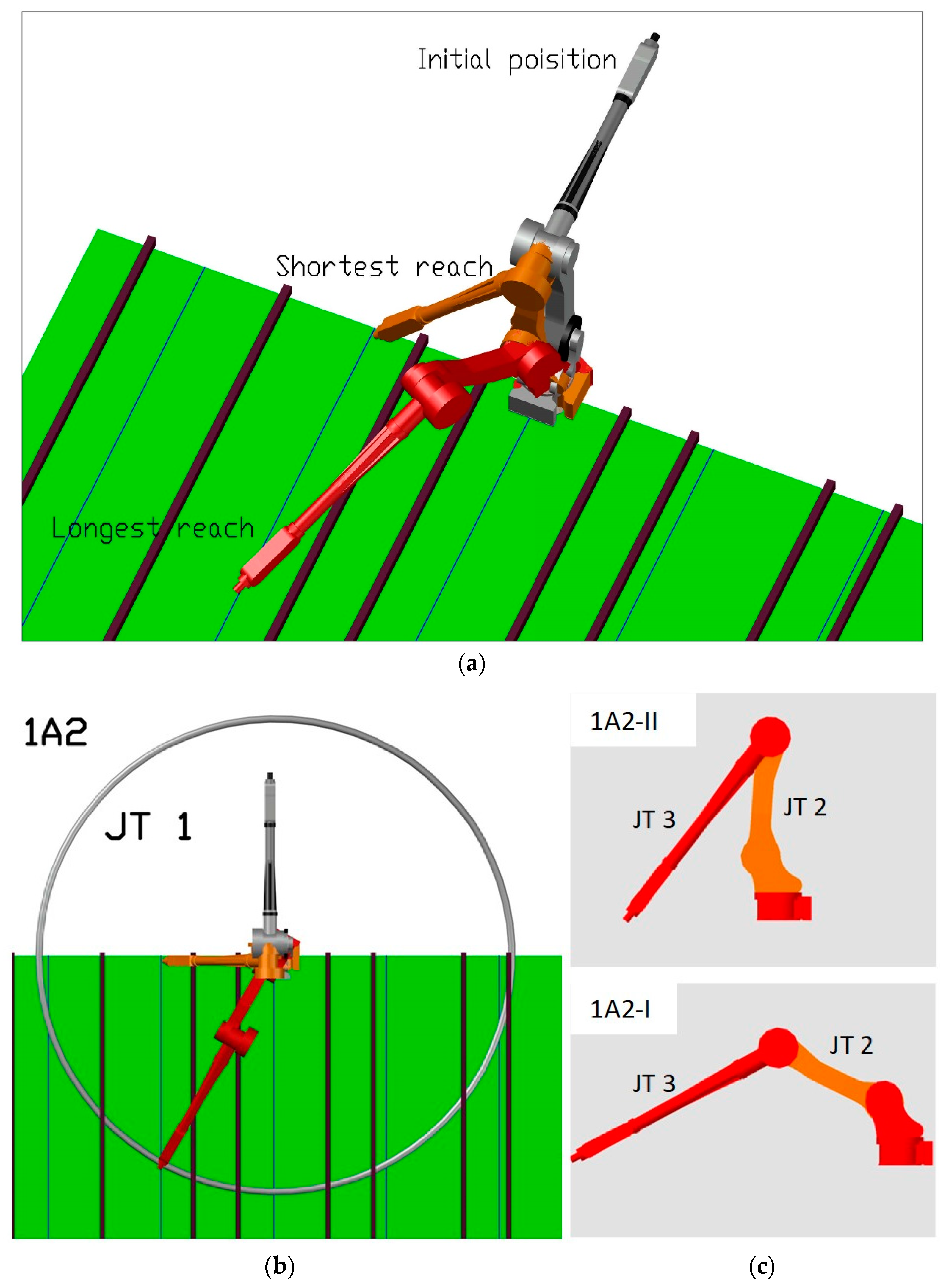
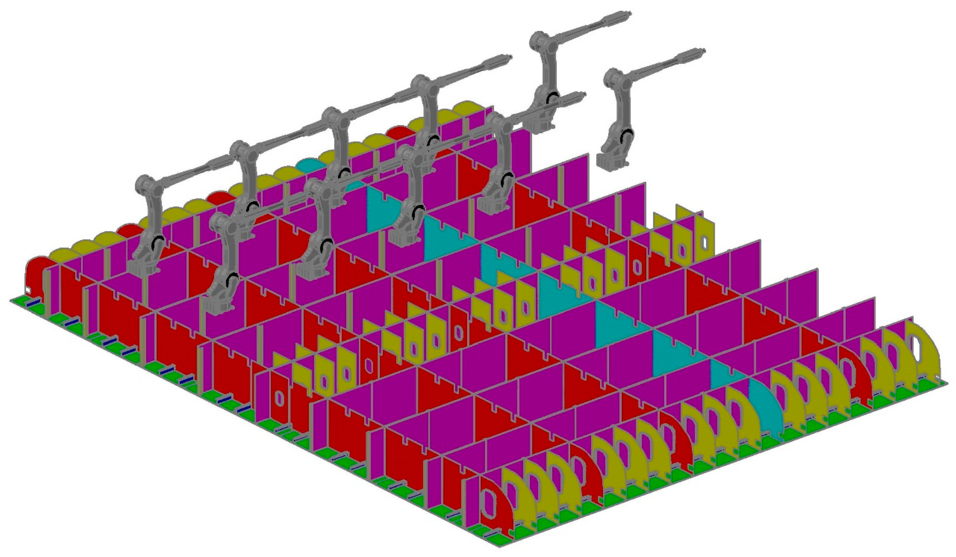
2.3. Robotic Welding Procedure

The initial step in the robotic welding procedure involves joining the outer plates, which have been fabricated based on the cutting plan design, with longitudinal stiffeners, using submerged arc welding (SAW). This process forms the inner bottom panel. To achieve an efficient welding speed, the robotic welding travel speed of 1.5 m/min or 25 mm/s is combined with the arm speed, following the high-speed one-side submerged arc welding process [29]. To calculate the welding time, the length required to weld 8 longitudinal stiffeners, each measuring 12 m, is analyzed.
To optimize the movement and speed of the robot arm, the area for welding the inner bottom panel is divided based on the specified range and speed of the robot, as outlined in the specifications. The panel consists of plates measuring 12 m × 1.5 m with a thickness of 12 mm, and is supported by 12 m long longitudinal stiffeners. This division enables determination of the robot’s optimal movement and arm speed during the welding process.
In the subsequent stage, a simulation is performed to analyze the robot welding process for the double-bottom stiffeners. This simulation focuses on assessing the reachability of the robot arm within the specific conditions of the baseline robot, positioned at the height of the double-bottom structure. Given the complexity of the structure’s design, a comprehensive 3D simulation is utilized to accurately identify the areas accessible by the robot arm. The robotic welding travel speed of 1500 mm/min or 25 mm/s, as specified by the A7 MAG Welder’s 350/450 specifications, incorporates the arm speed.
Subsequently, the total time required to join the ship’s double bottom is utilized for an economic analysis, comparing the costs of conventional welding and robotic welding. The economic aspect primarily focuses on comparing operational costs and direct labor expenses between the two welding methods.

3. Results and Discussion

In this section, the utilization of robotic welding for a ship’s double-bottom assembly is simulated and analyzed, considering both technical and economic performance. The results derived from the technical and economic analysis are presented and discussed.

3.1. Technical Analysis

Welding quality is crucial for hull strength and ship safety. When initial cracks occur in the main structure, the critical applied torque is sharply reduced [30]. According to Hong et al. [31], fillet welded connections perform worse under fatigue as the length of the unwelded zone increases. Consequently, to avoid stress concentration and fatigue cracks, the welding junction must be executed perfectly, with a precise bead shape. The effectiveness of automatic welding techniques should be carefully considered by considering factors such as welding quality, the working environment, and cost efficiency, which includes both initial investments and operational costs. Due to the scope and complexity of the bottom structure, using the positioning system is essential for the successful implementation of robot welding. In this study, the positioning system is divided into two categories: outer panel joining and stiffener joining.

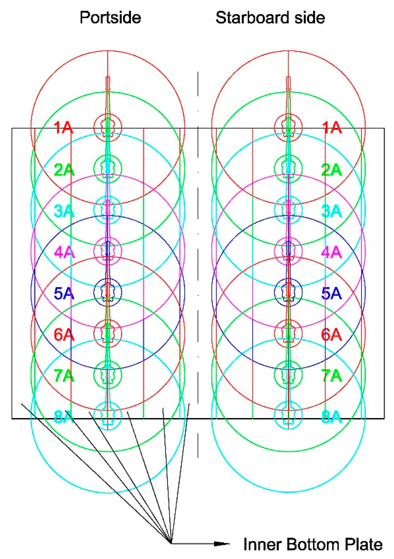
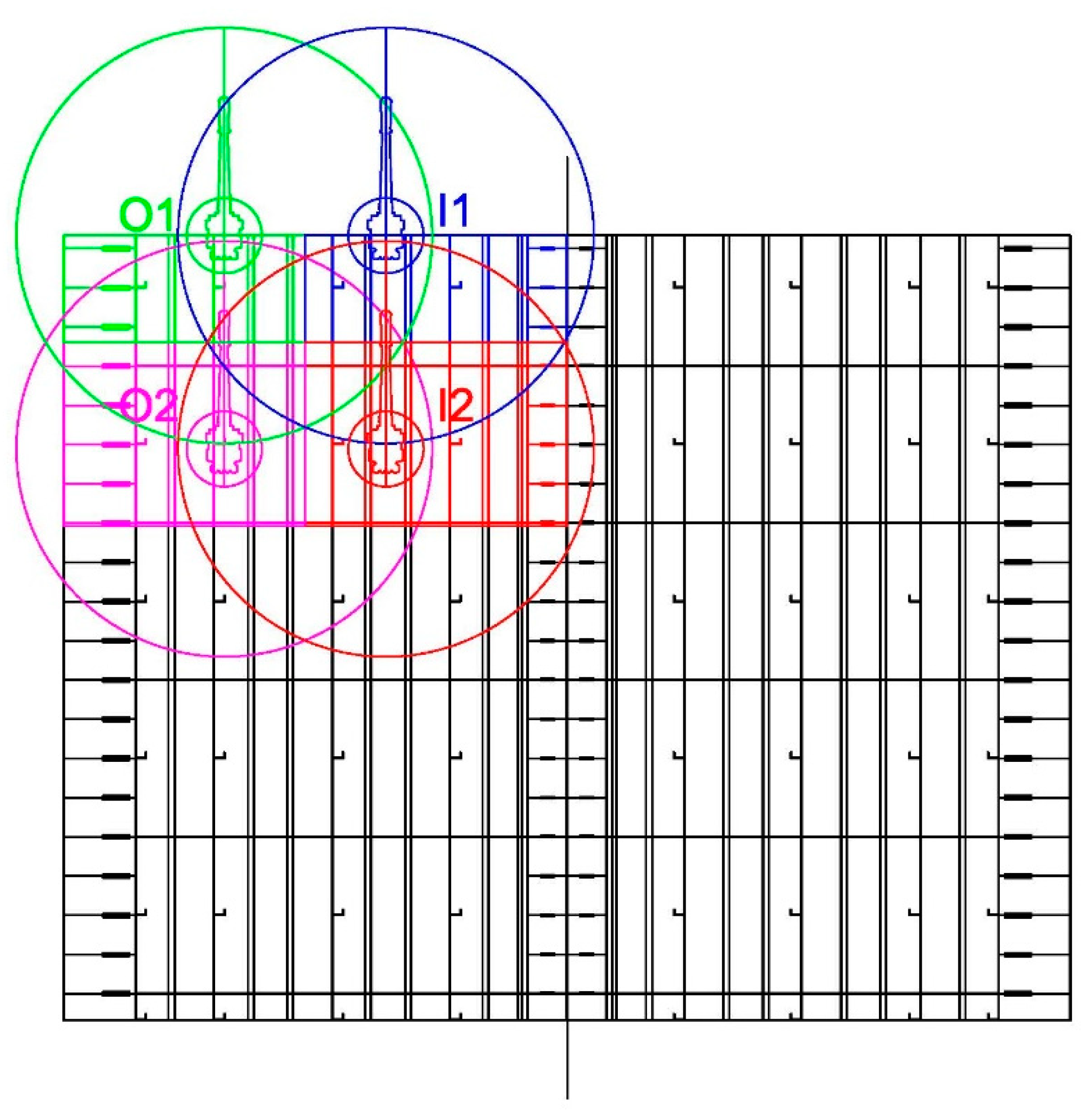
3.1.1. Outer Panel Joining

The outer plates are joined with longitudinal stiffeners using submerged arc welding (SAW) to form the inner bottom panel. The plates are fabricated according to the cutting plan design. The welding time calculation is conducted by first analyzing the welding length required to weld eight longitudinal stiffeners, each measuring 12 m. A 5% welding margin is added to the total welding length, resulting in a length of 403,200 mm. The total welding time is calculated by multiplying the welding length by the welding travel speed (1.5 m/min) based on the high-speed one-side submerged arc welding process [29] and applying an 80% safety factor, resulting in 15,372.7 s. Finally, the plates that have been equipped with longitudinal stiffeners are joined to form the inner bottom panel.
The area for welding the inner bottom panels is divided based on the range and speed of movement of the robot. This is done to optimize the welding process. The division is carried out to determine the optimal movement of the robot and the speed of the robot arm during the welding process. Figure 5a shows a three-dimensional visualization of the base plate welding process using robotic welding on the welding line. In Figure 5a, the silver color represents the initial position of the robotic welding, where the robot performs the farthest welding range in red and the closest range in orange.
Figure 5b shows the top view of the robot welding process on the inner bottom panel for the portside section with position 1A based on the coverage area of JT 1. The panel consists of plates measuring 12 m × 1.5 m with a thickness of 12 mm and is supported by longitudinal stiffeners, each measuring 12 m long. In that position, the robotic arm can weld 1A2 with a welding length of 2774.03 mm, as indicated by the blue line.
Figure 5c shows the side view of the movement of the welding robot arm with the coverage area of JT 2 and JT 3. The angle of arm movement is determined by the limitations of arm reach and robot arm length. This is necessary to reach the welding area. Position 1A2-I is the farthest point that the robot arm can reach in the welding groove, while 1A2-II is the closest point that the robot arm can reach in the welding groove. The speed of arm movement is determined based on the angle of arm motion. This allows the robot arm to reach positions 1A2-I and 1A2-II. According to the analysis of the movement and range of the robot, it was found that the robot moved 16 times for the port side and starboard side, as shown in Figure 6.
According to the maximum reach of the robot arm, the robot welding is transferred from the first to the eighth position, as shown in Figure 6. The transfer is supported by a railway to ensure optimal productivity and quality. The railway serves as a track for the robot arm to move along, providing stability and reducing the risk of damage to the workpiece. This allows the robot to move seamlessly from one position to another, without the need for additional setup or repositioning. Additionally, using a railway system can also help to optimize the robot’s trajectory, reducing the likelihood of collisions or other issues during the transfer process.
Based on the analysis of the movement of the robot arm, the total motion time is obtained, as shown in Table 1. The grey column shows the specification of the robot arm used in this study. The total motion time for each robot movement is obtained by adding up the total angles achieved by joining, as shown in Figure 6. From these scenarios, the length of the weld performed in each scenario of the robot arm movement can also be calculated, as shown in Table 2.
In order to comprehensively analyze the factors impacting welding quality, it is crucial to consider the welding position factors, as delineated in Table 2. These position factors are integral to the welding process, as they encompass varying levels of difficulty and directly influence the overall quality and strength of the welds. Some common welding positions are down hand (or flat position) and vertical positions, each of which presents unique challenges to the welder. The down hand position typically allows for easier manipulation of the welding torch or electrode, resulting in a more consistent weld bead and fewer defects. In contrast, the vertical position demands a higher level of skill and precision from the welder, as the molten weld pool is subject to gravitational forces that can affect the weld’s integrity. Consequently, recognizing and accounting for these position factors is essential to understand the factors that contribute to welding quality and develop strategies to optimize welding processes in various applications.
Furthermore, the speed of the arm is added to the robotic welding travel speed of 1.5 m/min, or 25 mm/s, based on the high speed one-side submerged arc welding process [29]. The total welding time is obtained by adding a margin and safety factor. This is shown in Table 2.

3.1.2. Stiffener Joining

In the subsequent stage of the research, a simulation is conducted to analyze the robot welding process for the double-bottom structure. This simulation focuses on determining the reachability of the robot arm based on its range and the specific conditions of the baseline robot positioned at the height of the double-bottom structure. The complex design of structure required a comprehensive 3D simulation to precisely identify the areas that the robot arm could reach.
The 3D simulation was used to carefully examine the welding area and determine the specific piece parts that fall within the range of the robot arm. The simulation took into account the spatial constraints and dimensions of the structure, enabling an accurate assessment of the areas where the robot arm can effectively perform the welding operation.
The welding zones were divided into outer and inner zones based on the reach of the robot arm. This was done for both the port and starboard sides of the double-bottom structure. This division allowed for a systematic and efficient approach to the welding process. Figure 7 visually represents the simulation results, showcasing the optimal areas for welding. The outer 1 (O1) area is depicted in green, indicating the region that is successfully reached and welded by the robot arm. Similarly, the inner 1 (I1) area is represented in blue, signifying the portion accessible for welding. The magenta-colored outer 2 (O2) area represents another region within the reach of the robot arm, while the red-colored inner 2 (I2) area designates an additional accessible section.
In addition, the arm speed is incorporated into the robotic welding travel speed of 1500 mm/min or 25 mm/s, as specified by the A7 MAG Welder’s 350/450 specifications using carbon steel filler material. The total welding time for each piece is determined by considering the margin and applying a safety factor. Table 3 provides an example of the outer and inner calculation. Subsequently, the same calculation procedure can be applied to all joining piece parts up to the fifth outer and inner zones for both the starboard and port sides.
The welding area is divided into different zones based on the reach of the robot’s arm, specifically JT1, JT2, and JT3. The baseline position for the robot is set at the height of the double bottom, as shown in Figure 8. This helps to optimize the reach and movement of the robot. The length and angle of the welding area are then measured in the outer and inner zones (O1/I1–O5/I5), based on the reach of the robot arm. This analysis identifies 20 optimal positions for welding in the construction of the double bottom.
Furthermore, to ensure the robot arm can effectively reach the welding area of various construction components, such as side girders and brackets, the angle of the arm is measured using motions JT2 and JT3. This information enables the determination of the robot arm’s movement speed. Figure 9 provides a visualization of the arm reach simulation specifically for stiffener welding.
The simulation helps to optimize the welding process for the double-bottom structure by systematically dividing the welding area, measuring the optimal positions, and assessing the arm movement. The simulation outcomes provide valuable insights into the feasibility and effectiveness of the robot welding process for the double-bottom structure. The simulation helps to streamline the welding operations by accurately identifying the optimal areas for welding. This ensures that the robot arm can efficiently carry out the required tasks within the specified zones.
The welding time for a double-bottom block from a general cargo ship measuring 12 m in length, 15 m in breadth, and 1.1 m in depth is determined to be 17.42 h, based on the analysis of the results and considering the welding robot displacement scenario, as shown in Table 4. In comparison to conventional welders, the assembly process of the double-bottom panel is carried out by certified welders specialized in the field of shipbuilding, with minimum qualifications of 1G (Flat), 2G (Horizontal), 3G (Vertical), and 4G (Overhead) positions. When employing conventional Flux Cored Arc Welding (FCAW) using carbon steel filler material with a welding speed of 6.7 mm/s [32], the welding time is estimated to be 67.12 h. This calculation is obtained by multiplying the welding length achieved using the conventional welding speed for FCAW.
The results of the study show that robotic welding is approximately 3.85 times faster than conventional welding. These results emphasize the significant time-saving advantage offered by robotic welding in comparison to the conventional approach.

3.2. Cost Comparison

In this section, an economic analysis is conducted to compare the costs of conventional welding and robotic welding. The discussion focuses on the cost of the components used in conventional welding for ship production. Subsequently, the costs of joining the double bottom through robotic welding are calculated. The estimations from both approaches are analyzed and compared to determine which method is more cost-effective.
The robotic welding equipment is 3.85 times faster than a conventional welder when joining the ship’s double bottom, according to the technical analysis. Consequently, the operational cost calculation is conducted by considering four instances of conventional welding and comparing them with a single instance of robotic welding equipment.
The incorporation of the total time required to join the ship’s double bottom as a determining factor in the calculation of electricity costs and man-hour costs has been recognized as a critical aspect of the research [33]. This integration provides a more accurate and comprehensive assessment of the overall costs associated with the shipbuilding process, and it also allows for a deeper understanding of the relationship between time and cost optimization.
In the analysis, various stages involved in the joining process have been carefully considered, taking into account the duration and complexity of each step. An accurate estimation of the resources required for the process can be achieved, including the electricity consumed during the welding and assembly stages, as well as the man-hours needed, by incorporating these factors into the calculations.
Moreover, the inclusion of time as a determining factor enabled the identification of potential bottlenecks and inefficiencies within the process. This led to the development of strategies for optimizing both time and cost, which ultimately led to a more efficient and cost-effective shipbuilding process.

3.2.1. Comparison of the Use of Electricity Costs

The operational costs incurred when using welding machines vary significantly between robot welding machines and conventional welding machines. This difference is due to the fact that robot welding machines consume more power than conventional welding machines. Specifically, the power specifications of the welding machines play a significant role. The conventional welding machine used in this study consumes 3000 watts of power, while the robot welding machine consumes 4500 watts of power.
The estimated electricity costs for robot welding machines and conventional welding machines are presented in Table 5 and Table 6, respectively. Table 5 shows that the total electricity cost for constructing a double-bottom block using a single robot unit is GBP 37.81. Conversely, if four units of conventional welding machines are used, the electricity cost is GBP 100.82. The analysis reveals that the utilization of a robotic welding machine can result in a substantial savings in electricity costs of 63% compared to conventional welding machines.

3.2.2. Comparison of Direct Labor Costs

Labor costs are costs associated with labor needs during the production process. Direct labor costs are the costs associated with the salaries or wages of the workers who are directly involved in the production of a product. In this research, the man-hour cost is based on the average welder’s salary per hour in the United Kingdom as reported in [34].
The direct labor cost for robotic welding in joining the double bottom panels is GBP 696.78, which includes the salaries of one robot operator, one fitter, and one helper, as shown in Table 7. In contrast, conventional welding is more expensive, with a total cost of GBP 1916.15, including the salaries of four welders, two fitters, and two helpers, as shown in Table 8. The analysis shows that using a robotic welding machine can save GBP 1219.37, or approximately 64% of the total man-hour costs incurred by conventional welding methods, as shown in Table 7 and Table 8.

3.2.3. Cost Recapitulation

The results of calculations are presented in Table 9, which summarizes the costs of electricity and man-hours for conventional welding and robotic welding. Table 9 shows that the total cost of electricity and man-hours for conventional welding is GBP 2016.97, while the total cost for robotic welding is GBP 734.59. This results in a cost ratio of 1:2.75. This comparison clearly demonstrates that the utilization of robotic welding can significantly reduce operational costs.
The findings of this study demonstrate the potential cost savings when using robotic welding techniques. The significant difference in costs highlights the efficiency and economic benefits of using robots for welding tasks. The lower cost of electricity and man-hours in robotic welding results in significant savings for the overall welding process. Companies can optimize their operations, improve cost effectiveness, and enhance their competitive edge in the industry by adopting robotic welding.

4. Conclusions

The manufacturing process of double-bottom ships, which are intricate structures, can benefit greatly from the implementation of robotic welding. Therefore, this study conducts technical and economic analyses of robotic welding and conventional methods for ship double-bottom construction. According to the findings of the technical analysis and the welding robot displacement scenario, it would take 17.42 h to weld a double-bottom block of a general cargo ship that is 12 m long, 15 m wide, and 1.1 m deep. Conversely, a welding duration of 67.12 h is obtained when utilizing standard FCAW welding with a welding speed of 6.7 mm/s. Based on these findings, robotic welding is 3.85 times faster than conventional welding for double-bottom welding tasks, meaning that it takes 3.85 times less time to weld a double-bottom block using a robotic welder than using a conventional welder.
The analysis of electricity and man-hour costs indicates that robot welding offers substantial cost savings compared to conventional welding. The total cost for conventional welding is GBP 2016.97, while the total cost of robotic welding is only GBP 734.59. This significant cost difference highlights that robotic welding is more efficient and cost-effective than conventional welding. When comparing the values of electricity and man-hours, the ratio between robot welding and conventional welding is 1:2.75. These findings show that robotic welding can reduce costs, which could lead to increased profits for companies. Companies can improve their operations, become more cost-effective, and gain a competitive advantage in the industry by using robotic welding technology.

Author Contributions

Conceptualization, S.I.W. and S.O.; methodology, S.I.W., S.O. and E.O.; software, S.I.W.; validation, S.I.W.; formal analysis, S.I.W.; investigation, S.I.W.; resources, S.I.W., S.O. and E.O.; data curation, S.I.W.; writing—original draft preparation, S.I.W.; writing—review and editing, S.O. and E.O.; visualization, S.I.W.; supervision, S.O. and E.O.; project administration, S.O. and E.O.; funding acquisition, S.I.W., S.O. and E.O. All authors have read and agreed to the published version of the manuscript.

Funding

The first author was financially supported by the Indonesia Endowment Fund for Education (LPDP), the Ministry of Finance, the Republic of Indonesia through the scholarship for the doctoral students.

Institutional Review Board Statement

Not applicable.

Informed Consent Statement

Not applicable.

Data Availability Statement

The data presented in this study are available on request from the corresponding author.

Acknowledgments

The authors wish to express their thanks to the Indonesia Endowment Fund for Education, the Ministry of Finance, the Republic of Indonesia, which provided the funding for this research. The authors are also grateful to several parties who contributed to the completion and evaluation of this research.

Conflicts of Interest

The authors declare no conflict of interest.

References

  1. Primo, T.; Calabrese, M.; Del Prete, A.; Anglani, A. Additive manufacturing integration with topology optimization methodology for innovative product design. Int. J. Adv. Manuf. Technol. 2017, 93, 467–479. [Google Scholar] [CrossRef]
  2. Lee, D.; Lee, S.; Ku, N.; Lim, C.; Lee, K.-Y.; Kim, T.-W.; Kim, J.; Kim, S.H. Development of a mobile robotic system for working in the double-hulled structure of a ship. Robot. Comput. Integr. Manuf. 2010, 26, 13–23. [Google Scholar] [CrossRef]
  3. Rea, P.; Ottaviano, E. Design and development of an Inspection Robotic System for indoor applications. Robot. Comput.-Integr. Manuf. 2018, 49, 143–151. [Google Scholar] [CrossRef]
  4. Okumoto, Y. Advanced Welding Robot System to Ship Hull Assembly. J. Ship Prod. 1997, 13, 101–110. [Google Scholar] [CrossRef]
  5. Ali, S.; Agrawal, A.P.; Ahamad, N.; Singh, T.; Wahid, A. Robotic MIG welding process parameter optimization of steel EN24T. Mater. Today Proc. 2022, 62, 239–244. [Google Scholar] [CrossRef]
  6. Liu, C.; Shen, J.; Hu, S.; Wu, D.; Zhang, C.; Yang, H. Seam tracking system based on laser vision and CGAN for robotic multi-layer and multi-pass MAG welding. Eng. Appl. Artif. Intell. 2022, 116, 105377. [Google Scholar] [CrossRef]
  7. Ferraguti, F.; Villani, V.; Storchi, C. MyWelder: A collaborative system for intuitive robot-assisted welding. Mechatronics 2023, 89, 102920. [Google Scholar] [CrossRef]
  8. Shin, J.G.; Sohn, S.J. Simulation-based evaluation of productivity for the design of an automated fabrication workshop in shipbuilding. J. Ship Prod. 2000, 16, 46–59. [Google Scholar] [CrossRef]
  9. Lezzi, F.; Costa, L. The development of conventional welding processes in naval construction. Weld. Int. 2013, 27, 786–797. [Google Scholar] [CrossRef]
  10. Lee, D.; Ku, N.; Kim, T.W.; Kim, J.; Lee, K.Y.; Son, Y.S. Development and application of an intelligent welding robot system for shipbuilding. Robot. Comput. Integr. Manuf. 2011, 27, 377–388. [Google Scholar] [CrossRef]
  11. Zhang, Q.; Xiao, R.; Liu, Z.; Duan, J.; Qin, J. Process Simulation and Optimization of Arc Welding Robot Workstation Based on Digital Twin. Machines 2023, 11, 53. [Google Scholar] [CrossRef]
  12. Feng, X.; Gao, L.; Tian, W.; Wei, R.; Wang, Z.; Chen, Y. Application of Wall Climbing Welding Robot in Automatic Welding of Island Spherical Tank. J. Coast. Res. 2020, 107, 1–4. [Google Scholar] [CrossRef]
  13. Chen, S.B. On the Key Technologies of Intelligentized Welding Robot. In Robotic Welding, Intelligence and Automation; Springer: Berlin/Heidelberg, Germany, 2007; LNCIS 362; pp. 105–115. [Google Scholar]
  14. Shapovalov, E.V.; Dolinenko, V.V.; Kolyada, V.A.; Skuba, T.G.; Klishchar, F.S. Application of robotic and mechanized welding under disturbing factor conditions. Pat. Weld. J. 2016, 7, 42–46. [Google Scholar] [CrossRef]
  15. Ang, M.H.; Wei, L.; Yong, L.S. An Industrial Application of Control of Dynamic Behavior of Robots—A Walk-Through Programmed Welding Robot. In Proceedings of the IEEE International Conference on Robotics & Automation, San Francisco, CA, USA, 24–28 April 2000; pp. 2352–2357. [Google Scholar]
  16. Feng, X.; Tian, W.; Wei, R.; Pan, B.; Chen, Y.; Chen, S. Application of a Wall-Climbing, Welding Robot in Ship Automatic Welding. J. Coast. Res. 2020, 106, 609–613. [Google Scholar] [CrossRef]
  17. Rooks, B. Robot welding in shipbuilding. Ind. Robot. An Int. J. 1997, 24, 413–417. [Google Scholar] [CrossRef]
  18. Kim, D.S.; Lee, H.K.; Seong, W.J.; Lee, K.H.; Bang, H.S. Experimental study on laser-mig hybrid welding of thick high-mn steel plate for cryogenic tank production. J. Mar. Sci. Eng. 2021, 9, 604. [Google Scholar] [CrossRef]
  19. Olschok, S.; Reisgen, U.; Dilthey, U. Robot application for laser-GMA hybrid welding in shipbuilding. In Proceedings of the International Laser Safety Conference, Cincinnati, OH, USA, 27–30 November 1990; Volume 605. [Google Scholar] [CrossRef]
  20. Rubeša, R.; Hadjina, M.; Matulja, T.; Fafandjel, N. Shipbuilding Decision-Making Optimization Based on the Functional Technical Documentation Information Level Usage in Ship Production. J. Ship Prod. Des. 2023, 39, 55–62. [Google Scholar] [CrossRef]
  21. Pribadi, T.W.; Adam, R.N.; Wahidi, S.I. Technical and Economical Analysis of Shipyard Re-Layout for Product-Oriented Work Breakdown Structure Implementation. IOP Conf. Ser. Mater. Sci. Eng. 2021, 1052, 012046. [Google Scholar] [CrossRef]
  22. Koenig, P.C. Technical and economic breakdown of value added in shipbuilding. J. Ship Prod. 2002, 18, 13–18. [Google Scholar] [CrossRef]
  23. Wahidi, S.I.; Virmansyah, V.M.; Pribadi, T.W. Study on Implementation of Activity-Based Costing (ABC) System on Determination of Indirect Costs in Ship Production. Kapal J. Ilmu Pengetah. Teknol. Kelaut. 2021, 18, 1–7. [Google Scholar] [CrossRef]
  24. Pribadi, T.W.; Shinoda, T. Hand Motion Analysis for Recognition of Qualified and Unqualified Welders using 9-DOF IMU Sensors and Support Vector Machine (SVM) Approach. Int. J. Technol. 2022, 13, 38–47. [Google Scholar] [CrossRef]
  25. Arif, M.S.; Supomo, H.; Alifia, W.U.; Wahidi, S.I. Ship production process monitoring application using QR-code technology. IOP Conf. Ser. Earth Environ. Sci. 2022, 972, 012016. [Google Scholar] [CrossRef]
  26. Eyres, D.J.; Bruce, G.J. Bottom structure. In Ship Construction; Butterworth-Heinemann: Oxford, UK, 2012; pp. 175–187. [Google Scholar] [CrossRef]
  27. Wahidi, S.I.; Pribadi, T.W.; Firdausi, M.I.; Santosa, B. Technical and Economic Analysis of a Conversion on a Single Pontoon to a Multi Pontoon Floating Dock. Nase More 2022, 69, 114–122. [Google Scholar] [CrossRef]
  28. Oliveira, A.; Gordo, J.M. Lean tools applied to a shipbuilding panel line assembling process. Brodogradnja 2018, 69, 53–64. [Google Scholar] [CrossRef]
  29. Oyama, S.; Kasuya, T.; Shinada, K. High-speed One-side Submerged Arc Welding Process ‘NH-HISAW’. Nippon. Steel Tech. Rep. 2007, 95, 17–21. [Google Scholar]
  30. Nguyen, C.T.; Oterkus, S. Investigating the effect of brittle crack propagation on the strength of ship structures by using peridynamics. Ocean Eng. 2020, 209, 107472. [Google Scholar] [CrossRef]
  31. Hong, K.; Oterkus, S.; Oterkus, E. Peridynamic analysis of fatigue crack growth in fillet welded joints. Ocean Eng. 2021, 235, 109348. [Google Scholar] [CrossRef]
  32. Sá de Sousa, J.M.; Lobato, M.Q.; Garcia, D.N.; Machado, P.C. Abrasion resistance of Fe–Cr–C coating deposited by FCAW welding process. Wear 2021, 476, 203688. [Google Scholar] [CrossRef]
  33. González-González, C.; Santos-ortega, J.L.; Fraile-garc, E.; Ferreiro-cabello, J. Environmental and Economic Analyses of TIG, MIG, MAG and SMAW Welding Processes. Metals 2023, 13, 1094. [Google Scholar] [CrossRef]
  34. Indeed. Welder Salary in England. Available online: https://uk.indeed.com/career/welder/salaries?from=top_sb (accessed on 22 February 2023).
Figure 1. Ship double-bottom structure.
Jmse 11 01506 g001
Figure 2. Ship double-bottom production stages.
Jmse 11 01506 g002
Figure 3. Six axes’ movements of the robotic welding.
Jmse 11 01506 g003
Figure 4. The range of the robotic welding arm.
Jmse 11 01506 g004
Figure 5. (a) Three-dimensional view of the arm range simulation; (b) top view of the arm range; (c) side view of the arm range.
Jmse 11 01506 g005
Figure 6. Robot transfer simulation.
Jmse 11 01506 g006
Figure 7. Simulation of robot arm reach when welding the double-bottom structure.
Jmse 11 01506 g007
Figure 8. Positioning of the robot welding in the double-bottom assembly process.
Jmse 11 01506 g008
Figure 9. Simulation of robot welding movement on the double bottom.
Jmse 11 01506 g009
Table 1. Motion time of the robotic arm required to join the inner bottom panel.
PartCodeJT 1JT 2JT 3JT 1JT 2JT 3JT 4JT 5JT 6JT 1JT 2JT 3Total Motion Time
Arm Angle (Degree)Robot Speed (Degree/s)Movement Time (s)s
Inner Bottom Panel1A6824162721801802004103606103.82.31.47.46
2A7864872501801802004103606104.42.71.38.32
3A7866482451801802004103606104.43.61.29.19
4A7866482451801802004103606104.43.61.29.19
5A7866482451801802004103606104.43.61.29.19
6A7576483291801802004103606104.23.61.69.45
7A9166912541801802004103606105.13.81.310.20
8A36840811618018020041036061022.30.64.89
Table 2. Total time taken to join the inner bottom panel using robot welding.
PartCodeTotal Motion TimeWeld LengthBoth SideSymmetricWeld LayerTotal Weld LengthTotal (+Margin 5%)Welding TimeWelding PositionTotal Time
(s)(mm)(mm)(mm)(s)(s)
Inner Bottom Panel1A7.467571.5622130,286.2431,800.551211.4Down hand1218.9
2A8.327029.1622128,116.6429,522.471124.7Down hand1133.0
3A9.198562.3222134,249.2835,961.741370.0Down hand1379.2
4A9.198562.3222134,249.2835,961.741370.0Down hand1379.2
5A9.198562.3222134,249.2835,961.741370.0Down hand1379.2
6A9.4510,302.3222141,209.2843,269.741648.4Down hand1657.8
7A10.207204.5322128,818.1230,259.031152.7Down hand1162.9
8A4.891671.842216687.367021.73267.5Down hand272.4
Table 3. Outer and inner calculations for assembling the stiffeners by robotic welding.
Piece PartCodeTotal Weld LengthTotal (+Margin 5%)Welding TimeWelding PositionWelding Position FactorTotal Time
(mm)(mm)(s)(s)
Bilge Floor—PlateO122,728.0023,864.40909.1Down hand1921.9
Bilge Floor—Side Girder29,700.0031,185.001188.0Vertical1.51200.7
Side Girder—Plate13,070.4813,724.00522.8Down hand1535.5
Side Girder Stiff.—Side Girder8800.009240.00352.0Vertical1.5364.7
Centre Bracket—PlateI17200.007560.00288.0Down hand1300.7
Centre Bracket—Centre Girder13,200.0013,860.00528.0Vertical1.5540.7
Side Girder—Plate13,070.4813,724.00522.8Down hand1535.5
Side Girder Stiff.—Side Girder8800.009240.00352.0Vertical1.5364.7
Centre Girder—Plate3267.623431.00130.7Down hand1143.4
Long. Stiff—Watertight FloorO23420.003591.00136.8Down hand1149.5
Long. Stiff—Solid Floor3420.003591.00136.8Down hand1149.5
Bilge Floor—Plate22,728.0023,864.40909.1Down hand1921.9
Bilge Floor—Side Girder19,800.0020,790.00792.0Vertical1.5804.7
Side Girder—Plate22,468.4023,591.82898.7Down hand1911.5
Side Girder—Side Girder Stiff.8800.009240.00352.0Vertical1364.7
Side Girder—Floor8800.009240.00352.0Vertical1.5364.7
Side Girder—Watertight Floor8800.009240.00352.0Vertical1.5364.7
Solid Floor—Plate18,810.2019,750.71752.4Down hand1765.1
Watertight Floor—Plate18,810.2019,750.71752.4Down hand1765.1
Long. Stiff—Watertight FloorI24560.004788.00182.4Down hand1195.1
Long. Stiff—Solid Floor4560.004788.00182.4Down hand1195.1
Centre Bracket—Plate7200.007560.00288.0Down hand1300.7
Centre Bracket—Centre Girder13,200.0013,860.00528.0Vertical1.5540.7
Side Girder—Plate22,468.4023,591.82898.7Down hand1911.5
Side Girder—Side Girder Stiff.8800.009240.00352.0Vertical1.5364.7
Side Girder—Floor8800.009240.00352.0Vertical1.5364.7
Side Girder—Watertight Floor8800.009240.00352.0Vertical1.5364.7
Centre Girder—Plate5617.105897.96224.7Down hand1237.4
Solid Floor—Plate16,057.6016,860.48642.3Down hand1655.0
Watertight Floor16,057.6016,860.48642.3Down hand1655.0
Table 4. Total time of the double-bottom block welding process.
PartWeld LengthWeld Length (+Margin 5%)Welding TimeTotal Welding Time
(mm)(mm)(s)(s)
Long. Stiff—Plate384,000.00403,200.0015,360.015,372.7
Inner bottom panel237,865.48249,758.759514.69582.5
Zone O174,298.4878,013.402971.93022.9
Zone I145,538.1047,815.011821.51885.2
Zone O2135,856.80142,649.645434.35561.6
Zone I2116,120.70121,926.744644.84784.9
Zone O394,086.0898,790.383763.43852.6
Zone I382,606.9086,737.253304.33406.1
Zone O490,261.1294,774.183610.43699.6
Zone I480,065.2084,068.463202.63304.5
Zone O5106,287.40111,601.774251.54340.6
Zone I594,887.1099,631.463795.53897.3
Total Weld Length1,618,967.03mm
1618.97m
Total Welding Time (+safety factor robot 80%)62,710.36s
1045.17min
17.42h
Table 5. Electricity cost per double bottom for robotic welding.
ItemsValueUnit
Welding robot operating hours per day8h
Duty cycle60%
The current used (information based on a survey of welding wire products)320–500Amps
Welding robot device power4500Watt
Power consumption of electricity for welding robot36kWh
Number of welding robot operators1Person
Number of welding robots1Unit
Cost of electricity per kWh (based on UK tariff)0.32 GBP
Operation costs (Electricity consumption × Electricity cost per kWh)11.58 GBP
Overhead cost per day (20%)2.32 GBP
Margin (30%)3.47 GBP
Electricity cost per operating hours per day (8 h)17.36 GBP
Electricity cost per hours2.17 GBP
Welding time17.42 h
Electricity cost for a double bottom37.81 GBP
Table 6. Electricity cost per double bottom for manual welding.
ItemsValueUnit
Welder operating hours per day6h
Duty cycle45%
The current used (information based on a survey of welding wire products)300–350Amps
Welding machine power3000Watt
Power consumption of electricity for welding machines per day18kWh
Number of welders4People
Number of welding machines4Unit
Cost of electricity per kWh (based on UK tariff 2022)0.32GBP
Operation costs (Electricity consumption * Electricity cost per kWh)23.15GBP
Overhead cost per day (20%)4.63GBP
Margin (30%)6.95GBP
Electricity cost per operating hours per day (6 h)34.73GBP
Electricity cost per hours5.79GBP
Welding time (with 4 welders)17.42h
Electricity cost for a double bottom100.82GBP
Table 7. Man-hour cost for robotic welding (GBP).
NoWorkerQtyFee/hFee/a Double-Bottom Block
1Operator Robot115.00261.29
2Fitter115.00261.29
3Helper110.00174.20
SUM340.00696.78
Table 8. Man-hour cost for manual welding (GBP).
NoWorkerQtyFee/hFee/a Double-Bottom Block
1Welder415.001045.17
2Fitter215.00522.59
3Helper210.00348.39
SUM840.001916.15
Table 9. Comparison of the conventional and robot welding costs for a double-bottom block.
NoItemsCost (GBP)Note
ConventionalRobot
1Electricity100.8237.81Per Double-Bottom Block
2Man-Hours (MH)1916.15696.78Per Double-Bottom Block
Total2016.97734.59
Disclaimer/Publisher’s Note: The statements, opinions and data contained in all publications are solely those of the individual author(s) and contributor(s) and not of MDPI and/or the editor(s). MDPI and/or the editor(s) disclaim responsibility for any injury to people or property resulting from any ideas, methods, instructions or products referred to in the content.

