Article

Mean Drift Wave Forces on Arrays of Bodies Surrounded by Thin Porous Surfaces

by
Dimitrios N. Konispoliatis
and
Spyridon A. Mavrakos
*
School of Naval Architecture and Marine Engineering, National Technical University of Athens, 15773 Athens, Greece
*
Author to whom correspondence should be addressed.
J. Mar. Sci. Eng. 2023, 11(7), 1269; https://doi.org/10.3390/jmse11071269
Submission received: 18 May 2023 / Revised: 15 June 2023 / Accepted: 21 June 2023 / Published: 22 June 2023
(This article belongs to the Special Issue Hydrodynamics of Fish Cages and Floating Permeable Structures)

Abstract

:
A semi-analytical solution is presented for the evaluation of mean drift wave forces on arrays of structures composed of impermeable vertical cylindrical bodies and surrounded by thin, porous surfaces. The porous cell is assumed to have fine pores so that a linear pressure drop can be considered. The mean drift wave forces on the array are determined via two principally different approaches: the momentum conservation theory and the direct integration of all pressure contributions upon the bodies’ instantaneous wetted surfaces. A solution method that solves the corresponding diffraction problem following the multiple scattering approach is proposed to account for the hydrodynamic interaction phenomena between the waves and the bodies. Numerical results are presented which illustrate the consistency of each of the two approaches in accurately evaluating the mean wave drift forces on several examined array configurations. It is shown that the thin, porous surface significantly reduces the drift forces on the array of bodies, whereas at specific wave frequencies, local enhancements of the forces’ values are noted due to the amplified wave field between the members of the array.

1. Introduction

The interactions of ocean waves with the supporting columns of an offshore structure are of fundamental importance in its design. In this context, enhanced hydrodynamic interactions occur in arrays of bodies due to the amplification of the wave field via the continuous interactions of the propagating waves with the members of the array and the scattered waves among the solids, causing large, exciting wave loads and mean drift wave forces. This phenomenon is paramount, especially for arrays of multi-body arrangements, creating the so-called trapped-mode phenomenon. A trapped-mode phenomenon appears at specific wave frequencies at which the hydrodynamic loading components resonate and consequently elevate the waves in the fluid region between the bodies [1,2]. Therefore, the main challenge in arrays of large numbers of bodies is to not only withstand the prevailing environmental conditions at the installation location but also to predict the increased hydrodynamic wave loads on adjacent solids of the array, which are linked to the trapped waves.
There is a breadth of literature on porous structures and their effectiveness at reducing wave loads and wave reflections compared to impermeable solids. Specifically, porous, rubble-mound, and crip-type breakwaters are applied for shore protection since they can effectively reduce the transmitted and reflected wave heights. In addition, they allow water transmission between the open sea and the protected area. In [3,4], theoretical and numerical formulations for the prediction of ocean wave reflection and transmission at a permeable breakwater were presented and compared with corresponding experimental results. Also, in [5], a mathematical model for the transformation of a wave over a submerged breakwater was developed on the basis of the linearization of the equation that governs an unsteady flow through a porous medium. In [6], the influences of the breakwater’s geometry, the porous material properties, and the wave characteristics on the kinematics and dynamics over and inside a breakwater were examined by extending the mild slope equation for waves propagating on a porous layer. In [7,8], an application of the modified mild-slope equation for the evaluation of wave trapping by a porous breakwater was described. Recently, a pile-rock breakwater was examined [9], and an analytical solution for the interactions of a wave with the barriers was provided in the framework of the linear potential theory. A new analytical solution for wave reflection and transmission by a surface-piercing breakwater was also presented in [10]. Here, a modified water free surface condition was applied for the determination of the unknown expansion coefficients in the velocity potential expressions. A coupled eigenfunction expansion–boundary element method was presented in [11] for the interaction of surface waves with a submerged, semicircular porous breakwater placed on a porous seabed. It was concluded that up to 90% of the incoming wave energy could be dissipated by the breakwater. In addition, in [12], a comparative study on the hydrodynamic performances of porous and non-porous submerged breakwaters was conducted. From the presented experiments, the effect of porosity on the wave transmission and reflection coefficients was highlighted, as was its effect as on the wave energy loss coefficient for three different types of breakwaters with various values of porosity. A comparative study on two different types of porous breakwaters, i.e., bottom-standing and surface-piercing, was presented in [13]. The study revealed that for a bottom-standing barrier, more waves in interface mode are transmitted and more waves in surface mode are dissipated. The opposite holds true for the surface-piercing breakwater.
The above-mentioned wave–structure interaction studies were mainly focused on porous breakwaters. In addition to these studies, a substantial research interest has been focused on the interaction of waves with porous submerged plates and surface-pierced cylindrical bodies. Regarding porous plates, in [14,15], a linearized potential wave theory was applied to investigate the scattering of waves by a submerged disk with pores, whereas in [16], the reflection coefficient of water waves interacting with a submerged horizontal porous plate was examined. Furthermore, in [17], the hydroelastic interactions between water waves and submerged porous elastic discs were investigated. The use of multiple discs in an array was found to be a promising approach for wave power dissipation. In addition, the use of a horizontal, flexible porous membrane as an effective composite breakwater type was examined in [18,19]. Specifically, a semi-analytical model based on a matched eigenfunction expansion method was presented, and it was concluded that an optimal porosity parameter can be obtained which results in better wave-blocking performance and a smaller vertical force on the flexible porous structure. The use of porous structures as a future design for wave energy absorption was considered in [20,21], in which a hydroelastic model was developed. Here, the effects of mooring stiffness and porous-effect parameters on the structure’s displacement were evaluated. In [22,23], the hydrodynamic loads on a circular porous plate which was submerged below a free surface were also presented.
As far as porous cylindrical bodies are concerned, in [24,25,26], a single impermeable, bottom-seated vertical cylinder with an exterior porous surface was examined numerically and experimentally. It was found that the existence of the porous shell could substantially reduce the hydrodynamic forces and the mean drift wave forces on the solid body. A truncated cylinder with an upper porous sidewall and an inner impermeable column was studied in [27,28]. It was concluded that the proper selection of the porous coefficient, as well as the cylinder’s geometric parameters, can reduce the surge and heave wave forces acting on the structure. In addition, in [29], a boundary element method for the evaluation of wave forces on structures composed of solid and porous surfaces was presented. Here, the porous surface was subjected to linear and quadratic pressure–velocity relations. In [30,31], a linear and a quadratic resistance law was applied to several porous structures of arbitrary shapes. It was found that the exciting forces on the porous geometries considered were 5–20 times smaller than on their solid body counterparts, whereas the mean drift wave forces on the porous cases were more than four times lower than in the impermeable cases. A single cylindrical body with a porous cover, bottom, and sidewall surfaces was examined in [32,33]. Here, the Haskind relations were applied, and an additional damping coefficient due to the porosity was found. Furthermore, a hydrodynamic analysis of a single surface-piercing, semi-porous compound cylinder, employing the methods of separation of variables and matched eigenfunction expansions for the velocity potential, was presented in [34,35,36]. It was found that an appropriate optimal ratio of various parameters such as radius, draught, and porosity can be established for to minimize the adverse hydrodynamic effects on the structure.
With respect to arrays of porous cylindrical bodies, in [37,38], the interaction of water waves with partially porous, truncated circular cylinders was investigated. The exciting wave forces and the wave run-up on the multibody arrangement were calculated for various porosity coefficients and wave conditions. Also, in [39], an array of porous circular cylinders with and without inner porous plates was theoretically and experimentally investigated in order to evaluate the transmission rate of the propagating waves. Toward this goal, the cylinders’ draughts, the locations of the inner porous plates, and the spacing between the adjacent bodies were adjusted for the optimization of the wave dissipation. Finally, in [40], the exciting forces and the free surface elevation around an array of dual porous cylinders were evaluated for various bodies’ geometries, angles of wave propagation, and porosity coefficients.
The aim of the present paper is to take the analysis of multibody porous arrays a step further with the evaluation of the mean drift wave forces on the bodies for several-body arrangements. In arrays of finite impermeable bodies, the waves are trapped at specific wave frequencies within the local vicinity of adjacent solids, forming a near-standing wave with a much higher amplitude compared to the wave amplitude at other wave frequencies. Furthermore, in the analysis presented in [25] on a single porous cylinder, it was derived that local enhancements on the mean drift wave forces were attained at certain wave frequencies. Hence, the question that must be answered is whether these phenomena also occur for arrays of porous cylinders.
Mean drift wave forces are second-order forces and are small in magnitude compared to their first-order oscillatory counterparts. Nevertheless, although they do not influence the first-order oscillatory body’s motions, they may cause a large excursion from the body’s mean position in cases in which there is a lack of hydrostatic restoring forces [41,42]. Two principally different approaches have been presented in the literature for the evaluation of mean drift wave forces. The first approach, which is based on the momentum conservation principle, relates the forces on the body with the forces on the exterior control surfaces and the rate of change of the fluid momentum between the body and the control surfaces [41,43,44]. The second approach relies on the direct integration of the fluid’s pressure over the body’s wetted surface [45,46]. Nevertheless, both formulations require a solution for the corresponding linearized wave–body interaction problem, considering the hydrodynamic interaction phenomena between the bodies of the array.
In the present work, both the momentum and the direct integration methods are applied for the evaluation of the mean drift wave forces on arrays of porous cylindrical bodies. In the framework of the linear potential theory, the hydrodynamic interaction effects are determined via first-order potential solutions through the use of the multiple scattering approach, whereas the hydrodynamic characteristics of the bodies are evaluated using the method of matched axisymmetric eigenfunction expansions. The porous surface is assumed to be inflexible with fine pores so that a linear pressure drop can be considered. The existence of increased wave amplitudes in porous arrays is clearly demonstrated by the presented results. Nevertheless, the amplitudes of the waves are strongly dependent on the porous coefficient, the distance between the adjacent bodies, and the wave heading angle.

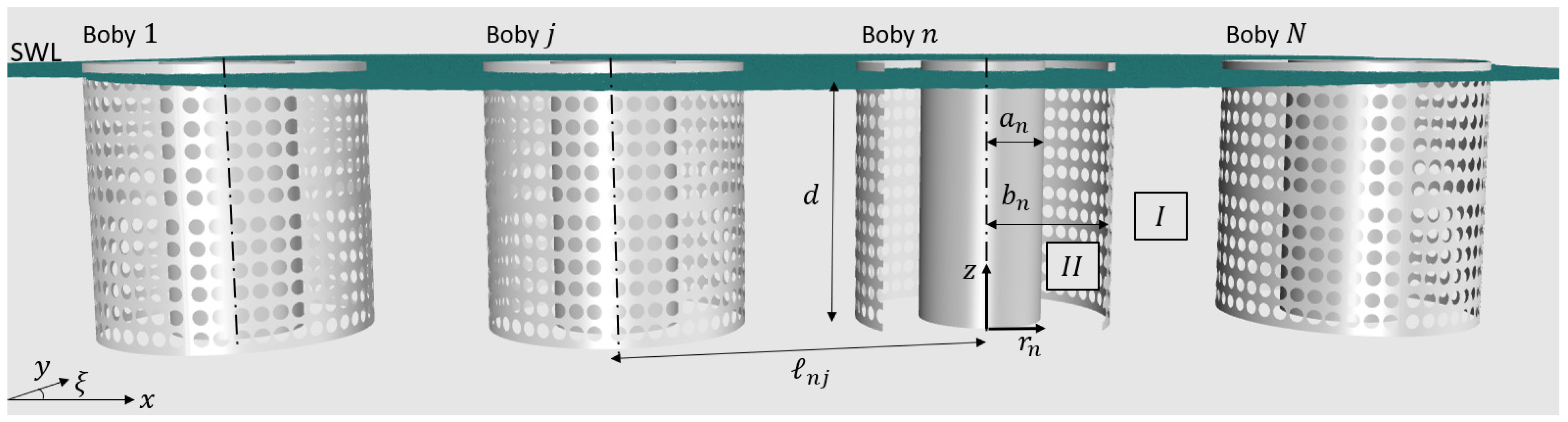
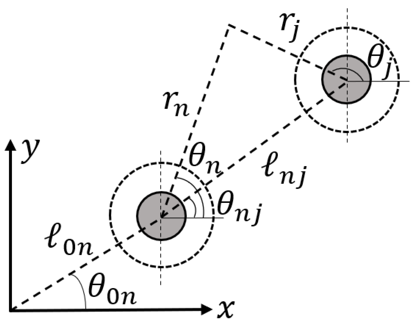
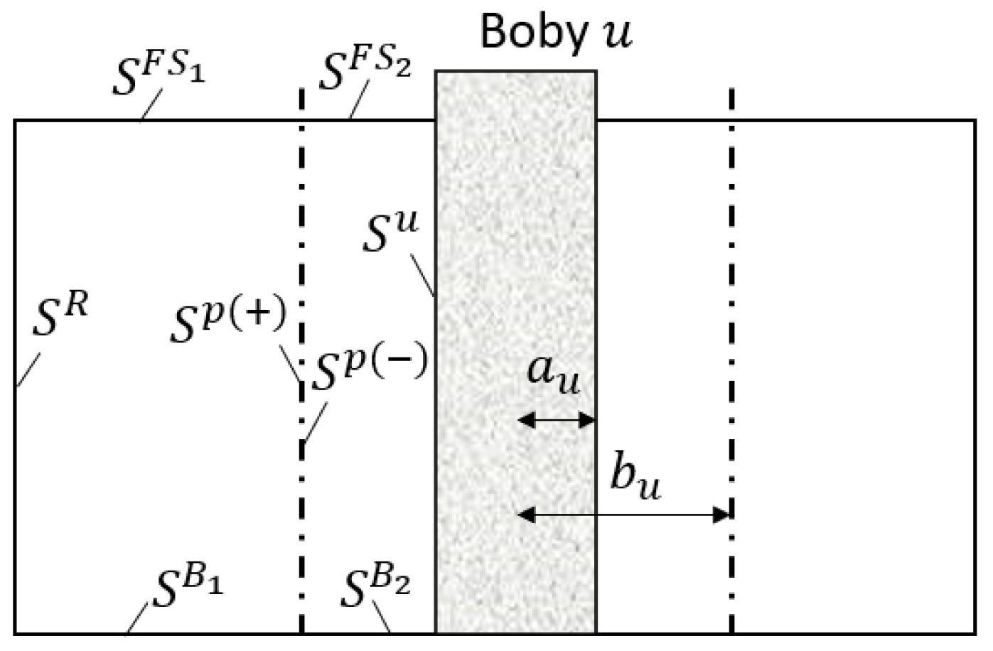
2. Hydrodynamic Formulation

An array of N bottom-seated impermeable vertical cylinders is assumed. The radius of each cylinder is a n , n = 1 , , N , whereas its draught, which coincides with the water depth, is d . Each cylinder is surrounded by an exterior thin, porous cylindrical cell of radius b n , n = 1 , , N . Also, N local cylindrical coordinate systems ( r n ,   θ n , z ), n = 1 , , N , are defined with their origins on the seabed and their vertical axes pointing upwards, coinciding with the vertical axis of symmetry of the n th body. The array is exposed to the action of a plane incident wave train of frequency ω , wave number k , and amplitude H /2, propagating at an angle of ξ with respect to the positive x -axis. The distance between the centers of two adjacent cylinders j and n is denoted by 𝓁 n j (see Figure 1). Within the framework of the linear potential theory, the fluid is assumed to be non-viscous and incompressible and the flow irrotational.
The flow field around each body n ,   n = 1 , , N of the array can be described by a velocity potential function Φ n as:
Φ n r n ,   θ n , z ; t = R e φ n r n ,   θ n , z e i ω t ,
whereas the spatial function   φ n can be decomposed as [47]:
φ n = φ 0 n + φ 7 n φ D n ,
Here, “ R e ” denotes the real part, whereas φ 0 n is the velocity potential of the undisturbed incident harmonic wave, and φ 7 n is the scattered potential around the n th body. Also, the sum of φ 0 n   and   φ 7 n is the diffraction potential φ D n .
The fluid field around the porous body n is subdivided into two coaxial ring-shaped regions, I and I I , i.e., I   r n b n and I I   a n r n b n . In each region, different expressions of the velocity potentials φ n can be made, i.e., φ I , n and φ I I , n for the regions I and I I , respectively. The velocity potentials φ q p , n ,   q = 0 , 7 ; p = I ,   I I ; n = 1 , , N , satisfy the Laplace equation in the fluid domain:
2 φ n = 0 ,
and the boundary conditions below.
The zero-velocity condition on the seabed:
φ n z = 0 ; on   z = 0 ,
the combined linear kinematic and dynamic boundary conditions of the water free surface:
ω 2 φ n g φ n z = 0 ; on   z = d ,
and a radiation condition which states that propagating disturbances must be outgoing [47].
Furthermore, since a fine-pore assumption is applied, φ D p , n must satisfy the boundary condition on the porous cell [36,48]:
φ D I I , n r n = i k G φ D I I , n φ D I , n ; on   r n = b n ,
whereas on the cylinder’s impermeable wetted surface S , the following boundary condition must be imposed [47]:
φ 7 I I , n r n = φ 0 I I , n r n ; on   r n = a n ,
In Equation (6), the term G stands for the dimensionless complex porosity coefficient. The coefficient can be written as: G = G R + i G I , where G R represents the linearized drag effect of the porous surface, and G I represents the inertia effect [36]. Furthermore, G also measures the porosity of the porous surface. Specifically, when G = 0 , the cell is considered impermeable to waves, whereas as G increases, the side cell becomes more permeable until no sidewall exists (i.e., the porous cell is completely permeable to fluid). The porosity coefficient is also linked to the opening rate τ of the porous surface (i.e., the ratio of the open area to the total area) and the wave slope ε = k H / 2 , found through Equation (8) [33]:
G = 17.8 ε   +   143.2 τ 2 2 π 1   +   1.06 τ   ,
Also, the wave number k satisfies the dispersion relation ω 2 = k g tan h k d , where g is the gravitational acceleration.
Finally, the velocity potentials, φ q p , n , are matched by the continuity requirements of the hydrodynamic radial velocity along the adjacent fluid regions I   and   I I [47]:
φ q I , n r n = φ q I I , n r n ; on   r n = b n   ,
The undisturbed incident velocity potential, φ 0 I , n , is expressed in the cylindrical coordinate system of the n th body as [49]:
φ 0 I , n r n ,   θ n , z = i ω H 2 m = i m Ψ 0 , m I , n r n , z e i m θ n   ,
Here, the term Ψ 0 , m I , n equals:
1 d Ψ 0 , m I , n r n , z = e i k 𝓁 0 n cos θ 0 n ξ Ζ 0 z d Z ˙ 0 d J m k r n e i m ξ   ,
The symbols 𝓁 0 n   and   θ 0 n are defined in Figure 2. Here, J m is the m th order Bessel function of the first kind, and ξ is the angle of the wave propagation. Also, Ζ 0 equals:
Ζ 0 z = N 0 1 / 2 cos h k z = 1 2 1 + sinh 2 k d 2 k d 1 / 2 cos h k z   ,
The term Z ˙ 0 d in Equation (12) denotes the derivative of Ζ 0 at z = d .
Similar to Equation (10), the diffraction velocity potential φ p , n ,   p = I , I I , in each fluid region around each body n , expressed in its own cylindrical coordinate system, is written as:
φ p , n r n ,   θ n , z = i ω H 2 m = i m Ψ D , m p , n r n , z e i m θ n   ,
In Equation (13), the terms Ψ D , m I , n and Ψ D , m I I , n denote the principal unknowns of the problem. These can be expressed appropriately around each body n when it is considered alone in the wave field, based on the method of separation of variables, i.e., [49]:
1 d Ψ D , m I , n r n , z = g D , m I , n r n , z + F D , m I , n H m k r n H m k b n   Z 0 z ,   for   r n b n   and   0 z d
where:
g D , m I , n r n , z = J m k r n J m k b n H m k b n H m k r n Ζ 0 z d Z ˙ 0 d     ,
Here, H m denotes the m th order Hankel function of the first kind. After introducing the term a 0 = i k , the m th order Bessel function of the first kind and the m th order Hankel function of the first kind can be expressed as functions of the m th order modified Bessel function of first kind, I m , and the m th order modified Bessel function of the second type, K m , respectively, i.e.,
I m i k r n = I m a 0 r n = i m J m k r n ,
K m i k r n = Κ m a 0 r n = i m + 1 H m k r n π 2 ,
Furthermore, it holds that:
1 d Ψ D , m I I , n r n , z = F D , m I I , n R m 0 I I , n + F D , m I I , n R m 0 I I , n   Z 0 z   for   a n r n b n   and   0 z d
where:
R m 0 I I , n = I m c 0 r n K m c 0 a n I m c 0 a n K m c 0 r n I m c 0 b n K m c 0 a n I m c 0 a n K m c 0 b n     , R m 0 I I , n = I m c 0 b n K m c 0 r n I m c 0 r n K m c 0 b n I m c 0 b n K m c 0 a n I m c 0 a n K m c 0 b n ,  
From Equation (19), it holds that for a n = 0 , i.e., the absence of the coaxial impermeable vertical cylinder, the functions R m 0 I I , n and R m 0 I I , n are reformed to:
R m 0 I I , n = I m c 0 r n I m c 0 b n ,     R m 0 I I , n = 0   ,  
In Equations (19) and (20), the term c 0 = i k . Furthermore, the eigenfunctions Z 0 are presented in Equation (12).
In order to express the velocity potential in the form of Equation (13) the multiple scattering approach was applied [49,50]. According to the method, the n th body of the array is, in the first stage, considered to be excited by the incident wave train, φ   1 0 p , n , which is expressed in Equation (10). In response to this first order of excitation, the n th body scatters the wave train, φ   1 7 p , n . This corresponds to a first order of a scattered wave for the n th body. Hence, φ   1 p , n = φ   1 0 p , n + φ   1 7 p , n . The total velocity potential around the multibody configuration can be written as:
φ   1 0 p , n + n = 1 N φ   1 7 p , n     ,  
Continually, the scattered waves of the first order represent waves of the “second” order of excitation for the body n :
φ   2 0 p , n = u = 1 N 1 δ n u φ   1 7 p , u     ,  
Here, δ n q is the Kronecher delta, with δ n u = 1 ,   n = u and δ n u = 0 ,   n u .
The total second-order potential of the n th body equals:
φ   2 p , n = φ   2 0 p , n + φ   2 7 p , n     ,  
where φ   2 7 p , n is the scattered wave of the “second” order radiated by the n th body.
Similarly, the s th order incident φ   s 0 p , n , scattered φ   s 7 p , n , and total φ   s p , n , wave potentials are derived by:
φ   s 0 p , n = u = 1 N 1 δ n u   φ   s 1 7 p , u , φ   s p , n = φ   s 0 p , n + φ   s 7 p , n     ,  
Assuming infinite wave interactions, the total incident waves to and the total scattered waves from the n th body are expressed as:
φ 0 p , n = s = 1 φ   s 0 p , n = φ   1 0 p , n + s = 2 u = 1 N 1 δ n u   φ   s 1 7 p , u , φ 7 p , n = s = 1 φ   s 7 p , n     ,  
In conclusion, the total velocity potential, φ p , n = φ 0 p , n + φ 7 p , n , will satisfy the corresponding boundary conditions presented above since the φ   s p , n wave potentials are already satisfying them. Following this method, the unknowns of the problem are the velocity potentials φ   s p , n . These can be written in the form of Equation (13) by substituting φ p , n with φ   s p , n and Ψ D , m p , n with Ψ   s D , m p , n .
The functions Ψ   s D , m p , n ,   p = I , I I are expressed in form of a Fourier series with coefficients F   s D , m q I , n ,   F   s D , m q I I , n ,   and   F   s D , m q I I , n , satisfying the corresponding conditions at the vertical boundaries of each fluid region: the linearized condition on the free surface, the boundary condition on the seabed, and the radiation condition at infinity. Consequently, a linear system of equations for the calculation of the Fourier coefficients in each fluid domain is obtained, and the total velocity potentials φ   s p , n are determined. It should be noted that the scattered waves, φ   s 1 7 p , u , also contribute to the total velocity potentials, φ   s p , n (see Equation (25)). These are, however, expressed in different coordinate systems compared to the coordinate system of the n th body. Therefore, the Bessel function addition theorem [51] is applied in order the s th order velocity potentials, φ   s p , n , to be expressed in the n th body’s coordinate system [52]:
K ν a 0 r u e i ν θ u = m = 1 m K ν m a 0 𝓁 n u I m a 0 r n e i v m θ n u e i m θ n ,   for   r u < β n u
where a 0 = i k .
By applying the method of multiple scattering, the n th body of the configuration is treated separately, taking into account the effect of the remaining bodies of the array on the n th body’s flow potential. Therefore, the s th order velocity potential, φ   s Ι , n , equals:
φ   s Ι , n = i ω H 2 m = i m   Ψ   s D , m Ι , n r n , z e i m θ n     ,  
Here,
1 d   Ψ   s D , m Ι , n r n , z = Q   s D , m I , n I m a 0 r n I m a 0 b n + F   s D , m I , n K m a 0 r n K m a 0 b n Z 0 z ,   for   r n b n   and   0 z d
In Equation (28), the term   Q   s D , m I , n equals:
Q   s D , m I , n = u = 1 N 1 δ u n v = i m + v K v m a 0 𝓁 u n K v a 0 b n I m a 0 b n   F   s 1 D , v I , u e i v m θ u n ,   for   s 2
whereas for s = 1 , the term Q   1 D , m I , n is obtained by:
Q   1 D , m I , n = i m e i k 𝓁 0 n cos θ 0 n ξ e i m ξ d Z ˙ 0 d I m a 0 b n   ,
In conclusion, for the total wave field   φ I , n , which is expressed by Equation (13), it holds:
1 d   Ψ D , m I , n r n , z = Q D , m I , n I m a 0 r n I m a 0 b n + F D , m I , n K m a 0 r n K m a 0 b n Z 0 z ,   for   r n b n   and   0 z d
where
Q D , m I , n = s = 1 Q   s D , m I , n ,   and   F D , m I , n = s = 1 F   s D , m I , n

3. Evaluation of the Mean Drift Wave Forces

Having determined the velocity potential around and inside the n th body of the array, the mean drift wave forces are evaluated from the quadratic products of the quantities obtained from the applied linear potential theory. In the present work, two alternative approaches for the evaluation of the mean drift wave forces are described. The first one is based on the direct pressure integration method, whereas the second is based on the principle of momentum conservation.

3.1. Direct Pressure Integration Method

According to this method, the mean drift wave forces on the multibody array are evaluated via the direct integration of the fluid pressure upon the instantaneous wetted surface of the u th body of the array, u = 1 , , N , keeping all terms up to the second order. Following [45,52], the vector of the mean drift wave forces on a porous and/or impermeable cylinder can be expressed as:
F 2 u ¯ T = 1 2 ρ g W L ζ r u 2 ¯ T F 1 2   n u d l + S u 1 2 ρ Φ u 2 ¯ T n u d S F 2 2 ,  
where ρ is the water density, n u is the unit normal vector pointing outwards toward the body, S u is the mean u th body’s wetted surface, and W L is the mean water line on the body. The bars   ¯ T denote the time average.
The total mean drift wave force on each porous cylindrical body of the array is equal to the sum of the mean drift wave forces on the porous surface with the corresponding forces on the impermeable surface of the coaxial vertical cylinder, whereas the mean drift wave forces on the porous surface are due to the difference between the fluid pressure on its outer and inner surfaces.
The term ζ r u stands for the first-order wave elevation with respect to the static water line, i.e.,
ζ r u 2 ¯ T = 1 2 R e ω 2 g 2 φ p , u φ p , u ¯ ,   p = I , I I ; u = 1 , , N
Here, the bar   ¯ denotes the complex conjugate of φ p , u .
Substituting Equation (34) into the first term of Equation (33), i.e., F 1 2 , and after normalizing the result with the term π ρ g b u H / 2 2 , the F 1 2 terms in the x and y directions, i.e., F 1 , x 2   and     F 1 , y 2 , respectively, are expressed:
F 1 , x 2 π ρ g b u H 2 2 = 1 2 ω 4 d 2 R b u g 2 Im m = Λ m , 0 Ζ 0 d Λ m + 1 , 0 Ζ 0 d ¯ ,
F 1 , y 2 π ρ g b u H 2 2 = 1 2 ω 4 d 2 R b u g 2 Re m = Λ m , 0 Ζ 0 d Λ m + 1 , 0 Ζ 0 d ¯ ,
Here, b u is the radius of the exterior thin, porous cylindrical cell of each body u . The term R equals b u for the evaluation of the mean drift wave forces on the porous cell, while R = a u for the evaluation of the corresponding forces on the inner impermeable vertical cylinder of the u th body. Also, the function Λ m , 0 is provided in Appendix A.
The second term of Equation (33), F 2 2 , for the x direction normalized by the term π ρ g b u H / 2 2 , equals:
F 2 , x 2 π ρ g b u H 2 2 = 1 2 ω 2 d 3 R b u g Im m = Λ ˙ m , 0 Λ ˙ m + 1 , 0 ¯ 1 R 2 m = m m + 1 Λ m , 0 Λ m + 1 , 0 ¯ + m = a 0 2 N 0 1 1 Λ m , 0 Λ m 1 , 0 ¯ Λ m + 1 , 0 ¯    
whereas the corresponding value for the y direction can be written as:
F 2 , y 2 π ρ g b u H 2 2 = 1 2 ω 2 d 3 R b u g Re m = Λ ˙ m , 0 Λ ˙ m + 1 , 0 ¯ 1 R 2 m = m m + 1 Λ m , 0 Λ m + 1 , 0 ¯ + m = a 0 2 N 0 1 1 Λ m , 0 Λ m 1 , 0 ¯ Λ m + 1 , 0 ¯ ,  
The term N 0 in Equations (37) and (38) is presented in Equation (12), while the function Λ ˙ m , 0 is given in Appendix A.
In conclusion, the mean drift wave forces on each body’s wetted surface (permeable and impermeable) in the x and y directions can be expressed as the sums of Equations (35), (37), (36) and (38), respectively.

3.2. Momentum Method

The hydrodynamic forces on each body u of an array of N bodies are equal to:
F u = S u p u n u d S = S u ρ Φ u t + 1 2 Φ u Φ u + g z n u d S ,
Here, p u denotes the fluid pressure on the u th body and n u is the unit normal vector to the boundary surface.
Based on the divergence theorem, we assume a finite control volume V u , which is bounded by the water free surface outside and inside the porous surface, S F S 1 ,   S F S 2 respectively; the seabed surface outside and inside the porous surface, S B 1 ,   S B 2 ; the impermeable body’s mean wetted surface, S u ; the body’s mean wetted porous surface, S p ; and a fixed vertical control surface, S R (see Figure 3).
Hence, Equation (39) can be rewritten as:
V u p u d V = V 1 u p u d V + V 2 u p u d V = S u S R S F S 1 S B 1 S B 2 S p + S F S 2 S p p n u d S ,
Here, the terms S p     and   S p + , denote the outside and inside mean wetted porous surfaces (see Figure 3).
From Equations (39) and (40), we obtain:
ρ V 1 u Φ u t + 1 2 Φ u Φ u + g z d V = ρ S R S B 1 S p + Φ u t + 1 2 Φ u Φ u + g z n u d S ,
ρ V 2 u Φ u t + 1 2 Φ u Φ u + g z d V = ρ S p S B 2 Φ u t + 1 2 Φ u Φ u + g z n u d S + F u ,
Applying the transport theorem to the first term of the volume integrals and the divergence theorem to the last two terms of the above volume integrals, the following equations are obtained:
d d t V u ρ Φ u d V = ρ V u Φ u t d V + ρ S Φ u ( U n u ) d S ,
1 2 ρ V 1 u , V 2 u Φ u Φ u d V = ρ S 1 , S 2 Φ u n Φ u d S ,
ρ g V 1 u , V 2 u z d V = k ρ g V 1 u , V 2 u d V = k ρ g S 1 , S 2 zn z d S   ,
where U is the velocity of the boundary surface S = S u S R S F S 1 S B 1 S B 2 S p + S F S 2 S p and n z is the z-component of the unit normal vector on these surfaces. Therefore, U n u = 0 on the fixed surfaces S R ,   S B 1 ,   and   S B 2 , and U n u = Φ n on the material surfaces, S u , S F S 1 , S p + , S F S 2 ,   and   S p . Also, k is the unit vector on the z-axis.
From Equations (41)–(45), we can write:
d d t V 2 u ρ Φ u d V ρ S p Φ u n Φ u d S k ρ g S F S 2 S p S u zn z d S = ρ S p Φ u t + 1 2 Φ u Φ u + g z n u d S + F u ,
d d t V 1 u ρ Φ u d V ρ S p + S R Φ u n Φ u d S k ρ g S F S 1 S p + zn z d S = ρ S p + S R Φ u t + 1 2 Φ u Φ u + g z n u d S ρ S B Φ u t + 1 2 Φ u Φ u n u d S ,
whereas from Equations (46) and (47), we obtain the horizontal forces on the u th body equal to:
F u = d d t V u ρ Φ u d V + ρ S R Φ u t + 1 2 Φ u Φ u + g z n u Φ u n Φ u d S ρ S p + S p Φ u n Φ u d S k ρ g S F S S u zn z d S + ρ S B Φ u t + 1 2 Φ u Φ u d S ,
Therefore, in order to evaluate the mean drift wave forces on an array of impermeable cylindrical bodies which is surrounded by porous surfaces, an additional term, ρ S p + S p Φ u n Φ u d S , should be evaluated, compared to the expression of the mean drift wave forces on an impermeable solid. This term of the mean drift wave forces, which are due to the energy dissipation through the external porous surface, can be expressed with respect to the horizontal directions x and y , i.e., F p o r o u s , x 2 and F p o r o u s , y 2 , respectively, as:
F p o r o u s , x 2 π ρ g b u H 2 2 = 1 2 ω 2 d 3 b u g Re i m = Λ ˙ m , 0 ( m 1 Λ m 1 , 0 ¯ + m + 1 Λ m + 1 , 0 ¯ ) +   ω 2 d 3 R b u g 2 Im m = Λ ˙ m , 0 Λ ˙ m + 1 , 0 ¯   ,
F p o r o u s , y 2 π ρ g b u H 2 2 = 1 2 ω 2 d 3 b u g Re m = Λ ˙ m , 0 ( m 1 Λ m 1 , 0 ¯ m + 1 Λ m + 1 , 0 ¯ ) ω 2 d 3 R b u g 2 Re m = Λ ˙ m , 0 Λ ˙ m + 1 , 0 ¯   ,
The terms Λ m , 0 and Λ ˙ m , 0 are presented in Appendix A, while the bar   ¯ denotes the complex conjugate.

4. Numerical Results

This section is dedicated to confirming the validity of the presented formulations and their computational implementation within the literature as well as to presenting the mean drift wave forces on different array configurations of impermeable vertical cylinders surrounded by porous surfaces.

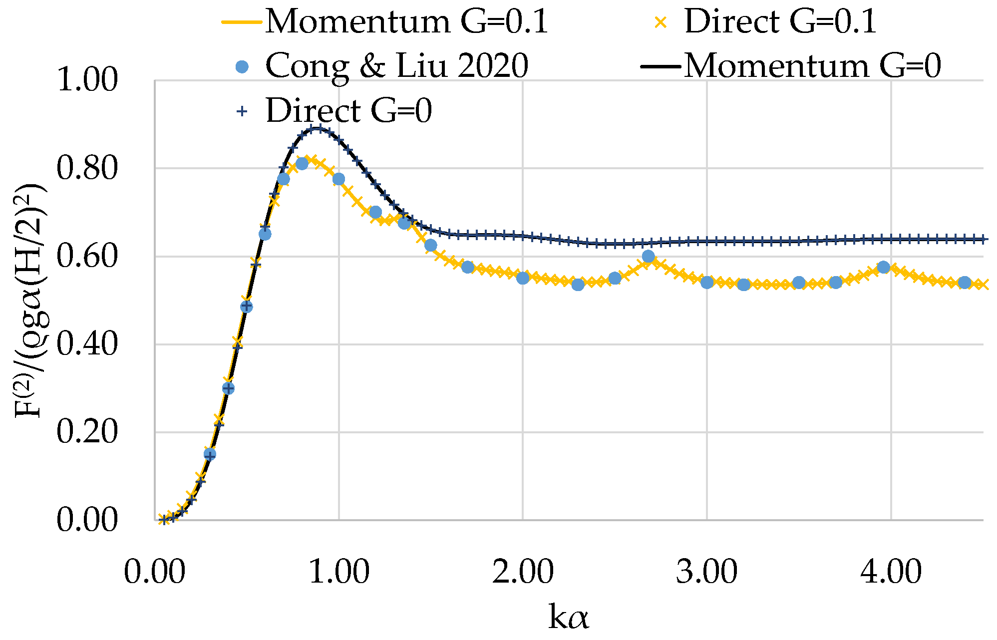
4.1. Result Validation

A single surface-piercing vertical impermeable cylinder surrounded by a porous surface is considered. The cylinder is bottom-seated at a water depth d = 3 a . The porous surface has a radius b , while the radius of the impermeable cylinder is a = 0.5 b . Two different porous coefficients are examined, i.e., G = 0 ; 0.1 . The mean drift wave forces on the porous structure (i.e., the impermeable cylinder and the porous surface), calculated using the two methodologies, are compared with the outcomes from [25] with excellent correlation. Specifically, in Figure 4, the horizontal mean drift forces on the structure are presented. The results are normalized by the factor ρ g a H / 2 2 . It can be seen that the outcomes of the presented methodologies (i.e., the momentum principle and direct integration method) attain similar results, which are also in excellent agreement with the results from [25]. Therefore, it can be concluded that the present formulation can effectively describe the mean drift forces on porous structures.
As far as the accuracy of the applied methodology with respect to the interaction phenomena between the bodies of an array is concerned (i.e., the method of multiple scattering), this is verified in Figure 5. Specifically, a four-cylinder array of bottom-mounted and free-surface-piercing porous cylinders in a square arrangement is considered (see Figure 5a). Here the cylinders are identical, each with a radius b . Also, d = 5 b , 𝓁 n j = 4 b , a n = 0 ,   n = 1 , , 4 , and ξ = 0 . Figure 5b depicts the total horizontal exciting forces in the x-direction on the four-cylinder array for several values of porous coefficients, i.e., G = 0 ,   1 ,   2 . The results are normalized by the term 2 π ρ g b 2 H / 2 and are compared with the results derived in the work of Williams and Li [48]. An excellent comparison with the outcomes from [48] can be seen in Figure 5b; hence, it can be concluded that the applied methodology can effectively describe the wave interaction phenomena between porous bodies of an array.

4.2. Test Cases

The objective of the numerical work carried out herein is twofold. Firstly, it aims to present the mean drift wave forces on arrays of porous bodies for several different array configurations, and secondly, it examines whether the near-trapped modes are also notable in the mean drift forces in dependence on the distances between the bodies and the porous coefficients. The array configurations chosen for the comparisons are illustrated in Figure 6. These form some indicative arrangements for supporting a pier, a floating building, and a floating PV system (an array of cylinders placed in a row, A1, and in star and hexagonal arrangements, i.e., A2 and A3, respectively) [53,54]. The bodies of the array are considered identical, with geometric characteristics as described in Section 4.1, i.e., d = 3 a ;   a = 0.5 b ;   b (see Figure 6).
The most consuming part of the numerical analysis is the evaluation of the Fourier coefficients in each fluid domain, I and I I . For the present calculations, q = 80 and m = 15 (i.e., 7 m 7 ) terms are considered for the velocity representation, whereas the number of interactions between the bodies of the array is taken equal to 7. These values are properly selected since it has been found that the outcomes of the present formulation are correct to within an accuracy of 1% [55,56]. The applied programming formulation sets the CPU time to less than one second for each wave frequency.

4.2.1. Effect of the Distance between the Bodies

First, the effect of the distance between the bodies of the array configurations on the mean drift wave forces is investigated. Here, the porous coefficient of the side surface is G = 0.1, while the wave heading angle is ξ = 0 . The examined distances between the centers of two adjacent cylinders are 𝓁 = 10 b ,   11 b ,   12 b . In Figure 7, the mean drift wave forces on the middle body of each examined array (i.e., body 4 for the A1, body 3 for the A2, and body 2 for the A3 configurations, see Figure 6) are depicted. The forces normalized by the term ρ g b H / 2 2 are derived based on the momentum principle and the direct integration method.
It can be seen from Figure 7 that the distance between the bodies of the array, as well as the array configuration, affect the mean drift forces. Clearly, the continuous interaction of the wave field diffracted by the bodies of the arrays with the incoming wave train causes strong disturbances which are reflected on the mean drift wave forces. Specifically, the variation pattern of the forces attains an oscillatory behavior, which is more tense for the A1 case (see Figure 7a) compared to the A2 and A3 cases (Figure 7b,c). Furthermore, the wave number in which this behavior begins is strongly dependent on the type of configuration i.e., the tense variation pattern of the forces begins at k b ~ 0.25 in A1, at k b ~ 0.40 in A2, and at k b ~ 0.60 in A3. Also, as the distances between the centers of the adjacent bodies increase, this oscillatory behavior is transferred to lower wave numbers. It is also noteworthy that there is an excellent correlation between the results obtained through the two computation methods. In Appendix B, the results from the two methodologies are presented in a table format for comparison purposes.
Regarding the trapped waves occurring around the bodies of the array, the A1 case is further examined since it exhibits amplified wave interaction phenomena between the members of the array compared to the A2 and the A3 cases [2,57]. Figure 8 depicts the comparisons of the mean drift wave forces, F 2 , normalized by the term π ρ g b H / 2 2 , on body 4 in the A1 case, with the horizontal exciting forces, F e x c , on the same body of the configuration. The latter are normalized by the term π ρ g b 2 H / 2 . Here, G = 0.1 and 𝓁 = 10 b . It can be observed that the exciting forces attain local maxima at specific wave numbers. In particular, the “Neumann” and “Dirichlet” trapped waves are noted, whereas the rest of the presented peaks (i.e., at   k b ~ 0.9 ,   1.2 ,   1.5 ) correspond to the “nearly trapped waves” occurring between the bodies. These trapped and nearly trapped waves are also noted in the mean drift forces; however, the drift forces have lower values compared to the exciting forces. Hence, it can be concluded that trapped mode phenomena also occur in the mean drift forces on a finite array of porous bodies.

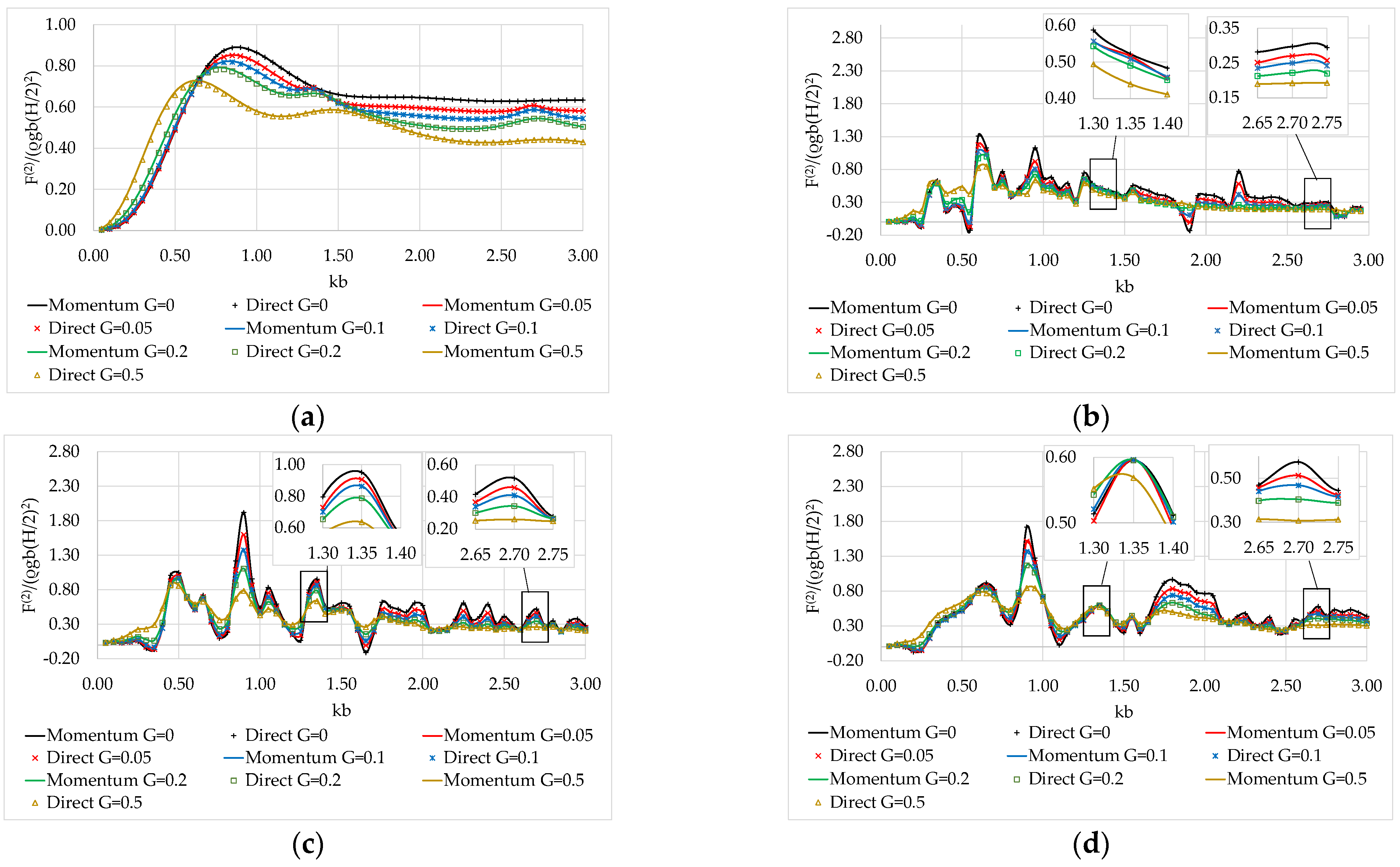
4.2.2. Effect of the Porous Coefficient

Next, the effect of the porosity coefficient on the mean drift forces acting on the considered arrays is examined. Here, the wave heading angle ξ = 0 and the distance between adjacent cylinders is 𝓁 = 10 b . Also, several values of G are examined, i.e., G = 0 ,   0.05 ,   0.1 ,   0.2 ,   0.5 . In Figure 9, the mean drift wave forces along the x -axis, on a single body of the array when it is considered isolated, and on the middle bodies of the examined arrays (i.e., body 4 for A1, body 3 for A2, and body 2 for A3) are presented. The results are derived based on the momentum principle and the direct integration method.
It can be seen from Figure 9a that the mean drift forces on the isolated body for G 0 differ from those for G = 0 . Specifically, the forces behave reverse proportionally with G . As the porosity coefficient increases, the forces decrease since the incident wave energy is absorbed by the side porous surface. On the other hand, the opposite trend seems to hold for small values of k b , i.e., k b < 0.6 . Furthermore, a series of peaks is depicted at k b ~ 1.35 ,   2.7 . At these wave numbers, local enhancements of the mean drift wave forces are attained which decrease as G increases. Following the conclusions of [25] for an isolated porous vertical cylinder, at these k b values, the dissipation effect of the side porous surface is significantly weakened; thus, the forces on the body tend toward those on an impermeable cylinder, whereas as G increases, this phenomenon is less pronounced. Regarding the mean drift wave forces on the body when it is considered part of an array, it can be seen (Figure 9b–d) that their variation pattern differs from that of an isolated body. In particular, a large oscillatory behavior appears which is enhanced reverse-proportionally with G . This can be attributed to the amplified wave field between the members of the array (see Section 4.2.1). Also, in comparison with the isolated case, the values of the mean drift forces on the examined arrays generally attain higher values. Furthermore, the decrease in the dissipation effect of the side porous surface at specific wave numbers also seems valid here. Nevertheless, the phenomenon is dominated by the large oscillatory behavior of the forces due to the wave interactions between the bodies of the array. Finally, from the comparison of the calculation methods of the mean drift wave forces it can be concluded that both methodologies attain similar results for the impermeable case ( G = 0 ) and for the permeable cases ( G 0 ).

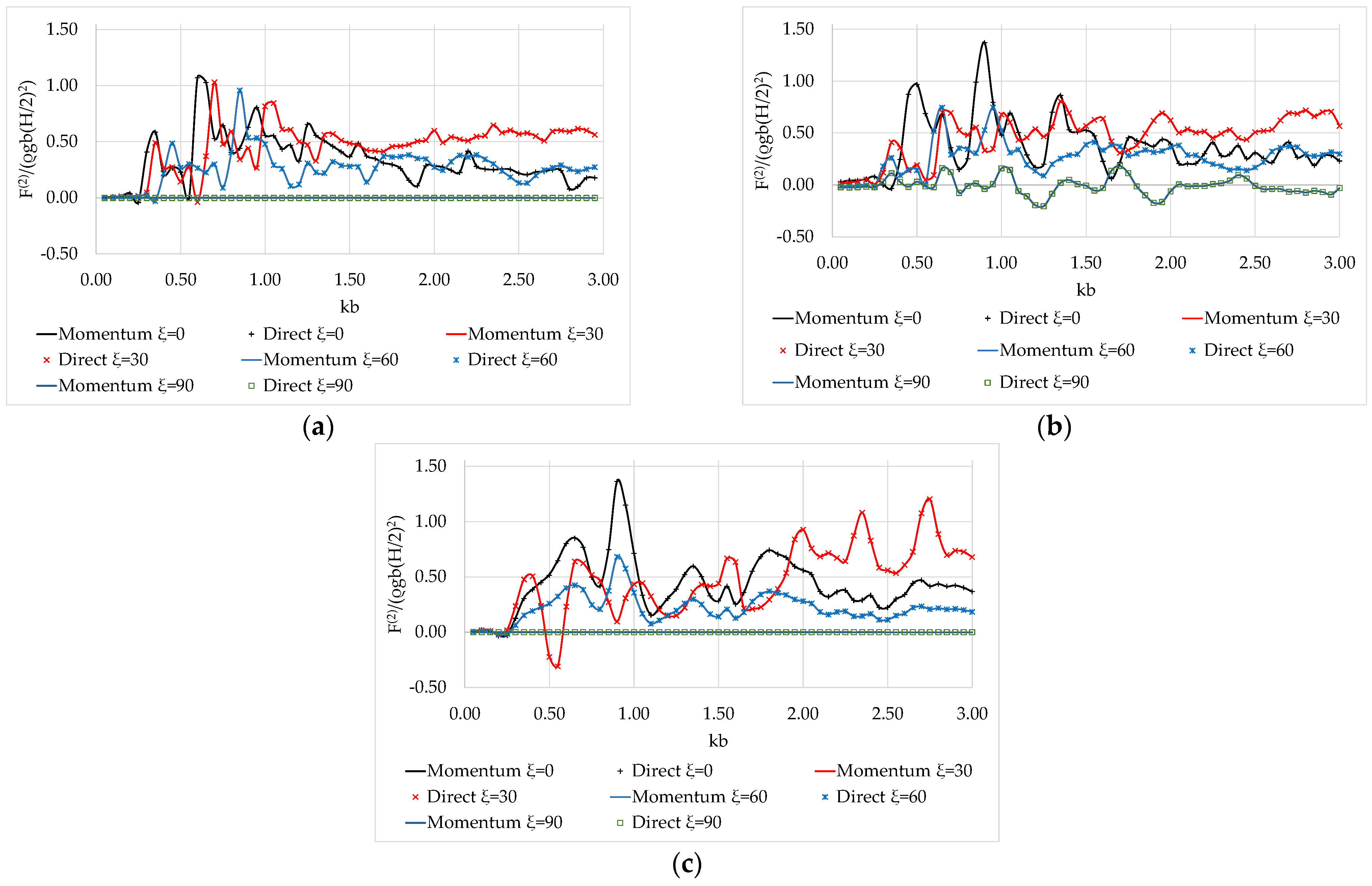
4.2.3. Effect of the Wave Heading Angle

In this subsection, the effect of the wave heading angle ξ on the mean drift forces of the examined arrays is presented. Here, the distance between adjacent bodies is 𝓁 = 10 b , and the porosity coefficient is G = 0.1 , and several wave heading angles are considered, i.e., ξ = 0 ,   30 ,   60 ,   90 degrees. In Figure 10, the mean drift wave forces on the middle body of the examined arrays (i.e., body 4 for the A1 configuration; body 3 for the A2 configuration; and body 2 for the A3 configuration), as evaluated via the momentum and the direct-integrations methods, are presented. Regarding the A1 configuration, it can be seen from Figure 10a that as the wave heading angle increases, the tense oscillatory behavior of the forces is transferred at higher values of k b , whereas due to the symmetry of the configuration, the forces on body 4 are zero for ξ = 90 . As far as the A2 case is concerned, the values of the mean drift forces on body 3 are comparable to those on body 4 in the case of A1, whereas here, the forces attain a non-zero value for ξ = 90 (see Figure 10b). Concerning the A3 configuration, it can be seen from Figure 10c that due to the symmetry of the array, the mean drift forces for ξ = 0 show a similar variation pattern as for ξ = 60 , whereas for ξ = 90 , the forces are zero. Finally, it can be concluded that the two methodologies applied for the evaluation of the mean drift wave forces attain similar results. In Appendix B, indicative results from the two methodologies are presented in a tabular format.

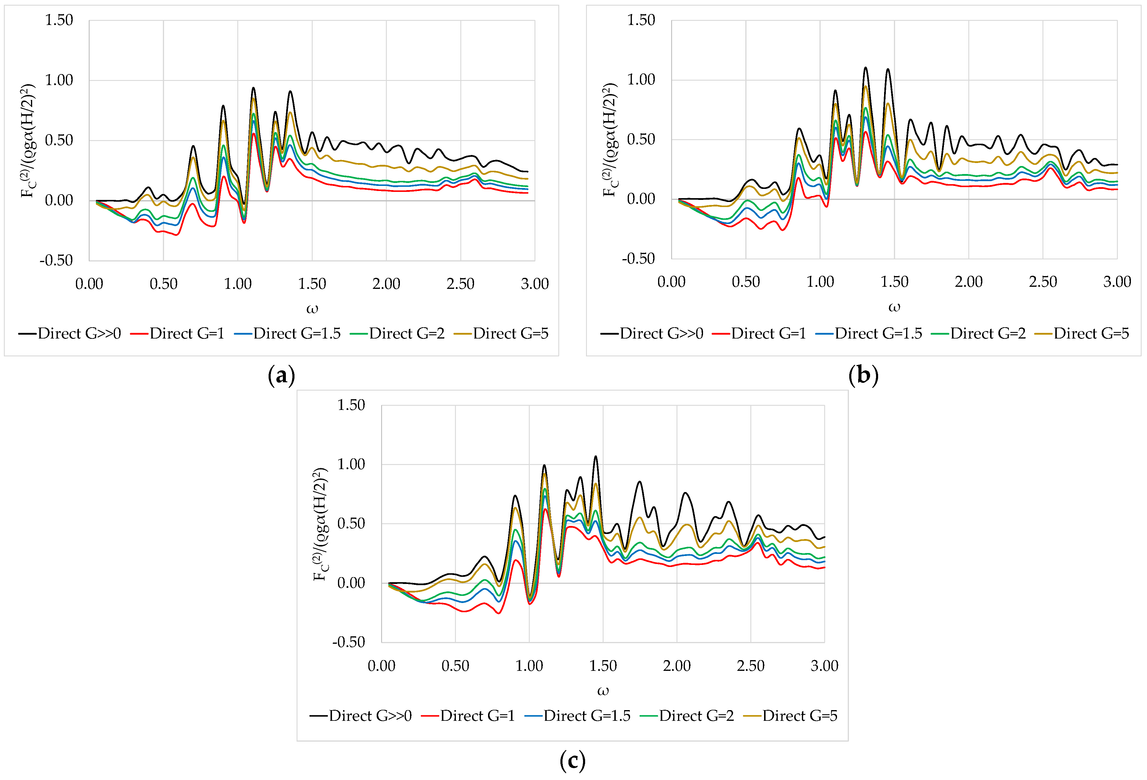
4.2.4. Effect of the Porous Side Surface on the Central Solid Body

Here, the effect of the porous side surface on the mean drift wave forces acting on the central solid body on the x -axis is examined. The drift forces on the central cylindrical surface of the middle body of each of the three examined array configurations, i.e., body 4 in case A1, body 3 in case A2, and body 2 in case A3, for G = 1 ,   1.5 ,   2 ,   5 , are compared with the corresponding ones on the same arrays of bodies without; however, the presence of the side porous surface, i.e., G 0 (the porous cell is completely permeable to fluid). The wave heading angle is ξ = 0 , and the distance between the vertical axes of adjacent bodies is 𝓁 = 10 b . Here, the direct integration methodology is applied. It can be seen from Figure 11 that the mean drift forces on the central body decrease as G increases in all examined cases. Hence, the side porous surface can effectively reduce the exciting forces on the central body. It is worth noting that this reduction in the mean drift forces due to the energy dissipation caused by the side porous surface is of major importance since in finite-number porous body arrays, wave trapped modes also occur. As a result, this type of porous body can become preferable for applications such as the protection of a semi-submerged floating structure in severe wave conditions.

5. Conclusions

This study considered the evaluation of the mean drift wave forces on arrays of circular cylinders surrounded by porous side surfaces. The methods employed relied on the momentum principle and the direct integration method and were based on semi-analytical formulations of the diffraction problem. A multi-parameter impact analysis was conducted regarding (a) the type of array configuration; (b) the distance between the members of the array; (c) the porosity coefficient of the side surface; and (d) the wave heading angle. A summary of the main conclusions of this work is as follows:
  • The variation pattern of the mean drift wave forces on a body when it is considered part of an array attains an oscillatory behavior that is dependent on the type of body arrangement. Nevertheless, this behavior is not valid for isolated solids. This can be traced back to continuous wave interactions with the bodies of the array, which cause strong disturbances on the mean drift wave forces;
  • Trapped and nearly trapped waves are also noted in the mean drift forces on a finite array of porous bodies with lower values when compared to their exciting counterparts;
  • The porosity coefficient G influences the mean drift wave forces. The oscillatory trend of the forces that appears is enhanced reverse-proportionally with G. Furthermore, the porosity of the side surface can effectively reduce the acting forces on the central impermeable body. This energy dissipation caused by pores can become preferable for applications such as the protection of a semi-submerged floating structure in severe wave conditions;
  • Finally, the semi-analytical model proposed in this study for the evaluation of the mean drift wave forces has demonstrated that both computational methodologies attain high-accuracy results.

Author Contributions

Conceptualization, D.N.K. and S.A.M.; methodology, D.N.K. and S.A.M.; software, D.N.K. and S.A.M.; validation, D.N.K.; formal analysis, D.N.K.; investigation, S.A.M.; writing—original draft preparation, D.N.K.; writing—review and editing, S.A.M.; visualization, D.N.K.; supervision, S.A.M. All authors have read and agreed to the published version of the manuscript.

Funding

This research received no external funding.

Institutional Review Board Statement

Not applicable.

Informed Consent Statement

Not applicable.

Data Availability Statement

The data supporting the findings of the present study are available upon request.

Conflicts of Interest

The authors declare no conflict of interest.

Appendix A

The function Λ m , 0 n ,   n = 1 , ,   N , presented in Equations (35)–(38), depends on the considered wave field. Thus, for the outer fluid domain I , it can be expressed as:
Λ m , 0 n = Q D , m I , n I m a 0 r n I m a 0 b n + F D , m I , n K m a 0 r n K m a 0 b n ,  
whereas for the inner fluid domain I I , it holds that:
Λ m , 0 n = F D , m I I , n R m 0 I I , n + F D , m I I , n R m 0 I I , n ,  
The functions R m 0 I I , n   and     R m 0 I I , n are presented in Equation (19).
The function Λ ˙ m , 0 , presented in Equations (37) and (38), corresponds to the derivative of Λ m , 0 with respect to r n . Therefore, for the outer fluid domain, it is written:
Λ ˙ m , 0 = Q D , m I , n 1 I m a 0 b n I m a 0 r n r n + F D , m I , n 1 K m a 0 b n K m a 0 r n r n ,  
whereas for the inner fluid domain, it holds that:
Λ ˙ m , 0 = F D , m I I , n R m 0 I I , n r n + F D , m I I , n R m 0 I I , n r n ,  

Appendix B

Table A1 depicts the results attained from the two methodologies for the evaluation of the mean drift forces on the x -axis on the middle body of each examined configuration. Here, G = 0.1 ,   𝓁 = 10 b ,   and   ξ = 0 , while the indicative wave numbers, k b , are considered for the three examined array configurations A1, A2, and A3. The results are normalized using the term π ρ g b 2 H / 2 .
Table A1. Mean drift wave forces on the middle body of each examined configuration for G = 0.1 ,   𝓁 = 10 b ,   and   ξ = 0 .
Configuration A1Configuration A2Configuration A3
k b MomentumDirectMomentumDirectMomentumDirect
0.30000.414580.409370.000670.000330.130200.12469
0.35000.589510.58488−0.03784−0.034570.309480.30457
0.60001.075801.070900.523730.518680.804310.79942
0.65001.029901.028200.681330.677220.852570.84807
0.70000.531720.527820.354130.359770.772010.76696
0.90000.632880.629431.372001.370101.364001.36220
1.00000.558550.557040.482370.480980.714500.71347
1.05000.552930.551520.693430.691880.335440.33374
1.15000.468900.467630.290840.289090.215170.21285
1.30000.556710.556430.700650.700380.521460.52087
1.35000.508520.508150.86290.862490.596920.59624
1.40000.458790.458290.532410.531890.502190.50146
1.60000.373140.372480.227450.226760.254140.25327
1.80000.261700.261460.425810.425460.740940.74061
2.00000.283230.283030.394970.394730.558340.55804
2.20000.415840.415730.301000.300910.364450.36429
2.40000.256340.256300.379280.379220.331720.33165
2.60000.228950.228960.216190.216240.338960.33904
2.80000.079980.080000.288800.288780.435520.43559
2.90000.178290.178310.277390.277420.422420.42255
In Table A2 the results from the two methodologies are presented for G = 0.1 ,   𝓁 = 10 b ,   and   ξ = 60 . The results are also normalized using the same term π ρ g b 2 H / 2 .
Table A2. Mean drift wave forces on the middle body of each examined configuration for G = 0.1 ,   𝓁 = 10 b ,   and   ξ = 60 .
Configuration A1Configuration A2Configuration A3
k b MomentumDirectMomentumDirectMomentumDirect
0.30000.025430.025430.182460.180130.065100.06234
0.3500−0.02926−0.030830.262170.261060.154760.15230
0.60000.268130.265320.520580.519590.402120.39968
0.65000.229880.226940.746810.745250.426290.42404
0.70000.301560.298920.293520.291440.386090.38557
0.90000.537530.536220.530070.529380.681850.68096
1.00000.479670.478260.524010.523780.357260.35675
1.05000.291830.290450.312080.311770.167750.16690
1.15000.106430.105510.195870.194970.107600.10644
1.30000.227630.227220.200190.199830.260690.26039
1.35000.220760.220280.254550.254160.298430.29809
1.40000.322550.322020.287800.287320.251060.25070
1.60000.142060.141680.333810.333330.127170.12774
1.80000.368020.367720.302320.302080.370450.37028
2.00000.273500.273340.362170.361980.279200.27905
2.20000.363760.363680.234020.233930.182200.18212
2.40000.239050.239030.157880.157810.165820.16579
2.60000.199340.199280.322190.322250.169440.16949
2.80000.256060.256060.297400.297480.217770.21781
2.90000.256340.256390.290410.290450.211150.21122

References

  1. Maniar, H.D.; Newman, N.J. Wave diffraction by a long array of cylinders. J. Fluid Mech. 1997, 339, 309–330. [Google Scholar] [CrossRef]
  2. Evans, D.; Porter, R. Near-trapping of waves by circular arrays of vertical cylinders. Appl. Ocean Res. 1997, 19, 83–99. [Google Scholar] [CrossRef]
  3. Sollitt, C.K.; Cross, R.H. Wave transmission through permeable breakwaters. In Proceedings of the 13th International Conference on Coastal Engineering, Vancouver, BC, Canada, 10–14 July 1972; pp. 1827–1846. [Google Scholar]
  4. Guo, Y.; Mohapatra, S.; Soares, C.G. Experimental study on the performance of an array of vertical flexible porous membrane type breakwater under regular waves. Ocean Eng. 2022, 264, 112328. [Google Scholar] [CrossRef]
  5. Rojanakamthorn, S.; Isobe, M.; Watanabe, A. A Mathematical Model of Wave Transformation over a Submerged Breakwater. Coast. Eng. Jpn. 1989, 32, 209–234. [Google Scholar] [CrossRef]
  6. Losada, I.; Silva, R.; Losada, M. Interaction of non-breaking directional random waves with submerged breakwaters. Coast. Eng. 1996, 28, 249–266. [Google Scholar] [CrossRef]
  7. Suh, K.D.; Park, W.S. Wave reflection from perforated-wall caisson breakwaters. Coast. Eng. 1995, 26, 177–193. [Google Scholar] [CrossRef]
  8. Zhu, S.; Chwang, A.T. Analytical Study of Porous Wave Absorber. J. Eng. Mech. 2001, 127, 326–332. [Google Scholar] [CrossRef]
  9. Liu, Y.; Li, H. Analysis of wave performance through pile-rock breakwaters. Proc. Inst. Mech. Eng. Part M J. Eng. Marit. Environ. 2014, 228, 284–292. [Google Scholar] [CrossRef]
  10. Liu, Y.; Li, H.-J. Wave reflection and transmission by porous breakwaters: A new analytical solution. Coast. Eng. 2013, 78, 46–52. [Google Scholar] [CrossRef]
  11. Koley, S.; Sahoo, T. Wave interaction with a submerged semicircular porous breakwater placed on a porous seabed. Eng. Anal. Bound. Elem. 2017, 80, 18–37. [Google Scholar] [CrossRef]
  12. Chyon, M.S.A.; Rahman, A.; Rahman, M.A. Comparative study on hydrodynamic performance of porous and non-porous submerged breakwater. Procedia Eng. 2017, 194, 203–210. [Google Scholar] [CrossRef]
  13. Kaligatla, R.B.; Tabssum, S.; Sahoo, T. Surface gravity wave interaction with a partial porous breakwater in a two-layer ocean having bottom undulations. Waves Random Complex Media 2021, 1–32. [Google Scholar] [CrossRef]
  14. Chwang, F.A.T.; Wu, J. Wave Scattering by Submerged Porous Disk. J. Eng. Mech. 1994, 120, 2575–2587. [Google Scholar] [CrossRef]
  15. Liu, Y.; Li, H.-J.; Li, Y.-C.; He, S.-Y. A new approximate analytic solution for water wave scattering by a submerged horizontal porous disk. Appl. Ocean Res. 2011, 33, 286–296. [Google Scholar] [CrossRef]
  16. Evans, D.V.; Peter, M.A. Asymptotic reflection of linear water waves by submerged horizontal porous plates. J. Eng. Math. 2011, 69, 135–154. [Google Scholar] [CrossRef] [Green Version]
  17. Meylan, M.H.; Greaves, D.; Iglesias, G. Water-wave interaction with submerged porous elastic disks. Phys. Fluids 2020, 32, 047106. [Google Scholar] [CrossRef]
  18. Guo, Y.; Mohapatra, S.; Soares, C.G. Wave energy dissipation of a submerged horizontal flexible porous membrane under oblique wave interaction. Appl. Ocean Res. 2020, 94, 101948. [Google Scholar] [CrossRef]
  19. Guo, Y.; Mohapatra, S.; Soares, C.G. Composite breakwater of a submerged horizontal flexible porous membrane with a lower rubble mound. Appl. Ocean Res. 2020, 104, 102371. [Google Scholar] [CrossRef]
  20. Mohapatra, S.C.; Guedes Soares, C. Hydroelastic behavior of a submerged horizontal flexible porous structure in three-dimensions. J. Fluids Struct. 2021, 104, 103319. [Google Scholar] [CrossRef]
  21. Mohapatra, S.; Soares, C.G. Surface gravity wave interaction with a horizontal flexible floating plate and submerged flexible porous plate. Ocean Eng. 2021, 237, 109621. [Google Scholar] [CrossRef]
  22. de Freitas, I.M.; Farina, L.; Miller, J.J. The heaving motion of a porous disc submerged in deep water. Ocean Eng. 2021, 219, 108290. [Google Scholar] [CrossRef]
  23. Zhao, F.; Zhang, T.; Wan, R.; Huang, L.; Wang, X.; Bao, W. Hydrodynamic loads acting on a circular porous plate horizontally submerged in waves. Ocean Eng. 2017, 136, 168–177. [Google Scholar] [CrossRef]
  24. Wang, K.-H.; Ren, X. Wave interaction with a concentric porous cylinder system. Ocean Eng. 1994, 21, 343–360. [Google Scholar] [CrossRef]
  25. Cong, P.; Liu, Y. Local Enhancements of the Mean Drift Wave Force on a Vertical Column Shielded by an Exterior Thin Porous Shell. J. Mar. Sci. Eng. 2020, 8, 349. [Google Scholar] [CrossRef]
  26. Vijayalakshmi, K.; Sundaravadivelu, R.; Murali, K.; Neelamani, S. Hydrodynamics of a Concentric Twin Perforated Circular Cylinder System. J. Waterw. Port Coast. Ocean Eng. 2008, 134, 166–177. [Google Scholar] [CrossRef]
  27. Teng, B.; Zhao, M.; Li, Y.C. Wave diffraction from a cylinder with porous upper wall and an inner column. ACTA Oceanol. Sin. 2001, 23, 6. [Google Scholar]
  28. Ning, D.-Z.; Zhao, X.-L.; Teng, B.; Johanning, L. Wave diffraction from a truncated cylinder with an upper porous sidewall and an inner column. Ocean Eng. 2017, 130, 471–481. [Google Scholar] [CrossRef] [Green Version]
  29. Mackay, E.; Liang, H.; Johanning, L. A BEM model for wave forces on structures with thin porous elements. J. Fluids Struct. 2021, 102, 103246. [Google Scholar] [CrossRef]
  30. Dokken, J.; Grue, J.; Karstensen, L.P. Wave analysis of porous geometry with linear resistance law. J. Mar. Sci. Appl. 2017, 16, 480–489. [Google Scholar] [CrossRef] [Green Version]
  31. Dokken, J.; Grue, J.; Karstensen, P. Wave forces on porous geometries with linear and quadratic pressure-velocity relations. In Proceedings of the 32nd International Workshop on Water Waves and Floating Bodies, Dalian, China, 23–26 April 2017. [Google Scholar]
  32. Bao, W.; Kinoshita, T.; Zhao, F. Wave forces on a semi-submerged porous circular cylinder. Proc. Inst. Mech. Eng. Part M J. Eng. Marit. Environ. 2009, 223, 349–360. [Google Scholar] [CrossRef]
  33. Zhao, F.; Bao, W.; Kinoshita, T.; Itakura, H. Theoretical and Experimental Study on a Porous Cylinder Floating in Waves. J. Offshore Mech. Arct. Eng. 2011, 133, 011301. [Google Scholar] [CrossRef]
  34. Sankar, A.; Bora, S.N. Hydrodynamic forces due to water wave interaction with a bottom-mounted surface-piercing compound porous cylinder. Ocean Eng. 2019, 171, 59–70. [Google Scholar] [CrossRef]
  35. Sankar, A.; Bora, S.N. Hydrodynamic forces and moments due to interaction of linear water waves with truncated partial-porous cylinders in finite depth. J. Fluids Struct. 2020, 94, 102898. [Google Scholar] [CrossRef]
  36. Sankar, A.; Bora, S.N. Hydrodynamic coefficients for a floating semi-porous compound cylinder in finite ocean depth. Mar. Syst. Ocean Technol. 2020, 15, 270–285. [Google Scholar] [CrossRef]
  37. Park, M.-S.; Koo, W. Mathematical Modeling of Partial-Porous Circular Cylinders with Water Waves. Math. Probl. Eng. 2015, 2015, 903748. [Google Scholar] [CrossRef] [Green Version]
  38. Park, M.S.; Koo, W.; Choi, Y. Hydrodynamic interaction with an array of porous circular cylinders. Int. J. Nav. Archit. Ocean Eng. 2010, 2, 146–154. [Google Scholar] [CrossRef] [Green Version]
  39. Zhao, F.-F.; Kinoshita, T.; Bao, W.-G.; Huang, L.-Y.; Liang, Z.-L.; Wan, R. Interaction between waves and an array of floating porous circular cylinders. China Ocean Eng. 2012, 26, 397–412. [Google Scholar] [CrossRef]
  40. Sankarbabu, K.; Sannasiraj, S.; Sundar, V. Interaction of regular waves with a group of dual porous circular cylinders. Appl. Ocean Res. 2007, 29, 180–190. [Google Scholar] [CrossRef]
  41. Mavrakos, S. The vertical drift force and pitch moment on axisymmetric bodies in regular waves. Appl. Ocean Res. 1988, 10, 207–218. [Google Scholar] [CrossRef]
  42. Konispoliatis, D.; Mavrakos, S. Mean Drift Forces on Vertical Cylindrical Bodies Placed in Front of a Breakwater. Fluids 2020, 5, 148. [Google Scholar] [CrossRef]
  43. Sclavounos, P.D. The vertical wave drift force on floating bodies. In Proceedings of the 2nd International Workshop on Water Waves and Floating Bodies, Bristol, UK, 16–19 March 1987. [Google Scholar]
  44. Molin, B. On second-order motion and vertical drift forces for three-dimensional bodies in regular waves. In Proceedings of the International Workshop on Ship and Platform Motion, Berkeley, CA, USA, 26–28 October 1983. [Google Scholar]
  45. Papanikolaou, A.; Zaraphonitis, G. On the improved method for the evaluation of second-order motions and loads on 3D floating bodies in waves. J. Schiffstechnik 1987, 34, 170–211. [Google Scholar]
  46. Shao, Y.L. Numerical analysis of second-order mean wave forces by a stabilized higher order boundary element method. In Proceedings of the 37th International Conference on Ocean, Offshore and Arctic Engineering, Madrid, Spain, 17–22 July 2018. [Google Scholar]
  47. Kokkinowrachos, K.; Mavrakos, S.; Asorakos, S. Behavior of vertical bodies of revolution in waves. Ocean Eng. 1986, 13, 505–538. [Google Scholar] [CrossRef]
  48. Williams, A.; Li, W. Water wave interaction with an array of bottom-mounted surface-piercing porous cylinders. Ocean Eng. 2000, 27, 841–866. [Google Scholar] [CrossRef]
  49. Mavrakos, S.; Koumoutsakos, P. Hydrodynamic interaction among vertical axisymmetric bodies restrained in waves. Appl. Ocean Res. 1987, 9, 128–140. [Google Scholar] [CrossRef]
  50. Twersky, V. Multiple Scattering of Radiation by an Arbitrary Configuration of Parallel Cylinders. J. Acoust. Soc. Am. 1952, 24, 42–46. [Google Scholar] [CrossRef]
  51. Watson, G.N. A Treatise on the Theory of Bessel Functions, 2nd ed.; Cambridge University Press: Cambridge, UK, 1966. [Google Scholar]
  52. Pinkster, J.A.; Oortmerssen, G.V. Computation of the first and second order wave forces on oscillating bodies in regular waves. In Proceedings of the 2nd International Conference on Numerical Ship Hydrodynamics, Berkeley, CA, USA, 19–21 September 1977. [Google Scholar]
  53. Offshore Wind Platform. Available online: https://www.offshorewind.biz/2012/02/17/hexicon-to-install-offshore-wind-platform-malta/ (accessed on 24 April 2023).
  54. AquaDomi Floating Hotels. Available online: https://www.cfmoller.com/p/AquaDomi-floating-hotels-i2339.html (accessed on 24 April 2023).
  55. Mavrakos, S.; McIver, P. Comparison of methods for computing hydrodynamic characteristics of arrays of wave power devices. Appl. Ocean Res. 1997, 19, 283–291. [Google Scholar] [CrossRef]
  56. Mavrakos, A.; Konispoliatis, D.; Ntouras, D.; Papadakis, G.; Mavrakos, S. Hydrodynamic coefficients in heave of a moonpool-type floater using theoretical, numerical and CFD methodologies. Ocean Eng. 2023, 279, 114519. [Google Scholar] [CrossRef]
  57. Chatjigeorgiou, I.K.; Chatziioannou, K.; Mazarakos, T. Near Trapped Modes in Long Array of Truncated Circular Cylinders. J. Waterw. Port Coast. Ocean Eng. 2019, 145, 04018035. [Google Scholar] [CrossRef]
Figure 1. Three-dimensional representation of the porous cylinder array case study exposed to the action sof regular waves. Definitions and discretization of the flow field around the bodies (SWL: sea water level).
Jmse 11 01269 g001
Figure 2. Schematic representation of the multi-body diffraction problem.
Jmse 11 01269 g002
Figure 3. Schematic representation of the bounded surfaces of a finite control volume around the u th porous body.
Jmse 11 01269 g003
Figure 4. Horizontal mean drift wave forces on a porous, bottom-mounted cylindrical body for different porous coefficients G based on the momentum principle and direct integration method. The results are compared against those reported in [25].
Jmse 11 01269 g004
Figure 5. Horizontal exciting forces on an array of four porous, bottom-mounted cylindrical bodies for different porous coefficients G : (a) schematic representation of the body arrangement; (b) horizontal exciting forces on the four-body configuration. The results are also compared with the outcomes from Williams and Li [48].
Jmse 11 01269 g005
Figure 6. Definition sketch of the examined array configurations: (a) Array A1; (b) Array A2; (c) Array A3. The solid line represents the impermeable surface of the vertical cylinder, whereas the dashed line represents the porous side surface.
Jmse 11 01269 g006
Figure 7. Mean drift wave forces on porous structures for different 𝓁 values: (a) on body 4 of A1; (b) on body 3 of A2; (c) on body 2 of A3.
Jmse 11 01269 g007
Figure 8. Comparison of the mean drift wave forces with the exciting forces on body 4 of A1 configuration.
Jmse 11 01269 g008
Figure 9. Mean drift wave forces on the porous structures for different G values: (a) on an isolated body; (b) on body 4 of A1; (c) on body 3 of A2; (d) on body 2 of A3.
Jmse 11 01269 g009
Figure 10. Mean drift wave forces on the porous structure for different ξ values: (a) on body 4 of A1; (b) on body 3 of A2; (c) on body 2 of A3.
Jmse 11 01269 g010
Figure 11. Mean drift wave forces on the central solid body for different G values: (a) on body 4 of A1; (b) on body 3 of A2; (c) on body 2 of A3.
Jmse 11 01269 g011
Disclaimer/Publisher’s Note: The statements, opinions and data contained in all publications are solely those of the individual author(s) and contributor(s) and not of MDPI and/or the editor(s). MDPI and/or the editor(s) disclaim responsibility for any injury to people or property resulting from any ideas, methods, instructions or products referred to in the content.

