Article

Underwater Color-Cast Image Enhancement by Noise Suppression and Block Effect Elimination

National-Local Joint Engineering Laboratory of Marine Mineral Resources Exploration Equipment and Safety Technology, Hunan University of Science and Technology, Xiangtan 411201, China
*
Author to whom correspondence should be addressed.
J. Mar. Sci. Eng. 2023, 11(6), 1226; https://doi.org/10.3390/jmse11061226
Submission received: 27 May 2023 / Revised: 8 June 2023 / Accepted: 12 June 2023 / Published: 14 June 2023
(This article belongs to the Section Physical Oceanography)

Abstract

:
Efficient underwater visual environment perception is the key to realizing the autonomous operation of underwater robots. Because of the complex and diverse underwater environment, the underwater images not only have different degrees of color cast but also produce a lot of noise. Due to the existence of noise in the underwater image and the blocking effect in the process of enhancing the image, the enhanced underwater image is still rough. Therefore, an underwater color-cast image enhancement method based on noise suppression and block effect elimination is proposed in this paper. Firstly, an automatic white balance algorithm for brightness and color balance is designed to correct the color deviation of underwater images and effectively restore the brightness and color of underwater images. Secondly, aiming at the problem of a large amount of noise in underwater images, a noise suppression algorithm for heat conduction matrix in the wavelet domain is proposed, which suppresses image noise and improves the contrast and edge detail information of underwater images. Thirdly, for the block effect existing in the process of enhancing the underwater color-cast image, a block effect elimination algorithm based on compressed domain boundary average is proposed, which eliminates the block effect in the enhancement process and balances the bright area and dark area in the image. Lastly, multi-scale image fusion is performed on the images after color correction, noise suppression, and block effect elimination, and finally, the underwater enhanced image with rich features is obtained. The results show that the proposed method is superior to other algorithms in color correction, contrast, and visibility. It also shows that the proposed method corrects the underwater color-cast image to a certain extent and effectively suppresses the noise and block effect of the underwater image, which provides theoretical support for underwater visual environment perception technology.

1. Introduction

An underwater robot is an important piece of equipment for humans to develop marine mineral resources and explore the origin of marine organisms. Efficient environmental perception is the key to realizing its autonomous operation [1,2]. Underwater environment perception mainly includes underwater visual environment perception and underwater acoustic environment perception. Compared with underwater acoustic environment perception, underwater visual environment perception has incomparable advantages, and especially when obtaining close-range environmental information, it can meet the high requirements of underwater robots for real-time and fineness of perception [3,4]. Due to the complex and diverse underwater environment, especially under the influence of different illumination or medium attenuation characteristics, underwater images have different degrees of color cast. The red component with a longer wavelength will decay and disappear at a very shallow depth, and the green component with a shorter wavelength and the blue component with a shorter wavelength will gradually decay and disappear with the increase in depth, so the underwater images often show green and blue [5,6]. At the same time, especially in turbid waters or the presence of a large number of microorganisms, underwater images will not only appear turquoise but also produce a lot of noise [7,8]. Because there is noise in the underwater image and a block effect will occur in the process of enhancing the image, the enhanced underwater color-cast image is still rough, which reduces the quality of the underwater image and affects the subsequent scholars’ scientific research on underwater activities. Therefore, how to correct the color deviation, suppress noise, and eliminate the blocking effect has become the focus of underwater image enhancement. This research can not only obtain high-quality underwater images but also provide theoretical support for underwater visual environment perception technology, which has wide practical application value and important theoretical significance.
At present, many scholars have carried out research on underwater color-cast image enhancement methods. Common physical model-based methods are widely used in image restoration, mainly by estimating model parameters to remove image blur. For example, Peng et al. [9] proposed a generalized dark channel prior (GDCP) method. The author estimates the scene transmittance by the difference between the observed light intensity and the ambient light and introduces adaptive color correction to remove the color cast. Chiang et al. [10] considered the influence of artificial light sources on underwater images and enhanced underwater images by defogging algorithms to improve image visibility and color fidelity. Jayasree et al. [11] combined WCID wavelength compensation with an image-defogging algorithm, which can eliminate the scattering and absorption effects of underwater scenes on images and produce certain effects. Galdran et al. [12] proposed a red channel image restoration method (ARC). The author improved the influence of artificial light source on the algorithm by adding saturation prior method, but the algorithm was not ideal for improving image contrast. The common physical model-based methods include UDCP [13] and IBLA [14]. However, due to the complexity of natural light and artificial light in the process of underwater real-time shooting, it is difficult to explain the relationship between water absorption and color attenuation using physical model-based methods. It is also difficult to estimate the parameters of the physical model. Therefore, the recovery of underwater images by physical model methods often introduces more serious color casts and reduces the overall contrast of the image. Therefore, people begin to use the method based on pixel intensity redistribution to process images. The image enhancement method based on the redistribution of pixel intensity is to change the pixel value in the spatial domain or transform domain, so as to produce better visual effects [15]. This method does not depend on any model and prior knowledge and has been widely used in the field of underwater image enhancement. For example, Ghani et al. [16] improved the contrast and color of underwater images by improving the recursive adaptive histogram. The author modified the pixel distribution of the histogram of the image according to the Rayleigh distribution, which improved the contrast of the underwater image and made the image more natural. Ancuti et al. [17] proposed an underwater image enhancement method based on color balance and fusion (FUSION). The authors’ method can effectively deal with the color-cast image and improve the global contrast of the image. Huang et al. [18] proposed the relative global histogram stretching (RGHS) method, which can effectively improve the visual effect of blurred images, but the effect on color-cast images is not obvious. Hou et al. [19] proposed an underwater color image enhancement method based on hue preservation. The authors used wavelet domain filtering (WDF) and constrained histogram stretching (CHS) algorithms to run on HSI and HSV color models, respectively, which effectively eliminated the noise of the image and improved the contrast of the image. Katırcıoğlu et al. [20] applied the heat conduction matrix to image enhancement, which effectively maintained the brightness of the image, sharpened the edge of the image, and enhanced the details of the color image. Mukherjee et al. [21] enhanced the color of the image in the compressed domain, which has better computational efficiency than the method based on the spatial domain. Bai et al. [22] proposed an enhancement method based on histogram global and local equalization and dual image multi-scale fusion, which achieved good results, but there are some limitations to dealing with turbid water images. In general, the methods based on image enhancement often ignore the physical characteristics of underwater light propagation, such as the degradation degree of underwater images and the depth information of the scene, so the color and texture information of underwater images cannot be completely restored. With the rapid development of deep learning, the Convolutional Neural Network (CNN) and the Generative Confrontation Network (GAN) have been widely used in underwater image enhancement. Li et al. [23] proposed a weakly supervised color conversion method to correct the color of underwater images. Yu et al. [24] proposed the Underwater-GAN model. The authors designed the loss function as the sum of the loss of the generative adversarial network and the perceived loss. In addition, an underwater image dataset was constructed using simulations, and underwater images were generated based on the underwater imaging model. The results show that this method has better visual effects than the existing methods. Pan et al. [25] combined a Convolutional Neural Network with a hybrid wavelet and directional filter bank (HWD) to enhance the edge of the image and obtain an image with outstanding details. Anwar et al. [26] made a comprehensive and in-depth review of underwater image enhancement methods based on deep learning and pointed out the advantages and disadvantages of this method. In general, the image enhancement method based on deep learning requires a large number of image datasets in practical applications, which increases the time cost and the consumption of computing resources, and the authenticity of the generated underwater image is hardly verified.
The above research can effectively enhance the underwater color-cast image to a certain extent, but there are also various deficiencies. In this paper, we focus on the influence of noise and block effects on underwater color-cast images. Therefore, an underwater color-cast image enhancement method based on noise suppression and blocking effect elimination is proposed, which is mainly composed of a brightness and color equalization module, noise suppression module, blocking effect elimination module, and multi-scale image fusion module. Firstly, an automatic white balance algorithm with brightness and color balance is designed to correct the color distortion of underwater images and effectively restore the brightness and color of underwater images. Secondly, aiming at the problem that there is a lot of noise in underwater images, a noise suppression algorithm of heat conduction matrix in the wavelet domain is proposed, which eliminates the noise of images and improves the contrast and edge details of underwater images. Thirdly, for the blocking effect in the process of enhancing the underwater color-cast image, an algorithm for eliminating the blocking effect in the compressed domain boundary average is proposed, which eliminates the blocking effect in the enhancement process and balances the bright and dark areas in the image. Lastly, the image after color correction, noise suppression, and block effect elimination is used as the input to the multi-scale image fusion module. Moreover, extract the dark channel weight, saturation weight, luminance weight, exposedness weight, saliency weight, and chromatic weight corresponding to the input image, respectively, then calculate the Laplacian value corresponding to the input image and the Gaussian value corresponding to the weight mapping, and finally carry out multi-scale image fusion to obtain the enhanced underwater image. The main contributions of this paper are summarized as follows:
(1)
An underwater color-cast image enhancement method based on noise suppression and blocking effect elimination is proposed, which can effectively correct the color distortion of underwater images, suppress noise and eliminate blocking effects, and provide theoretical support for underwater visual environment perception technology.
(2)
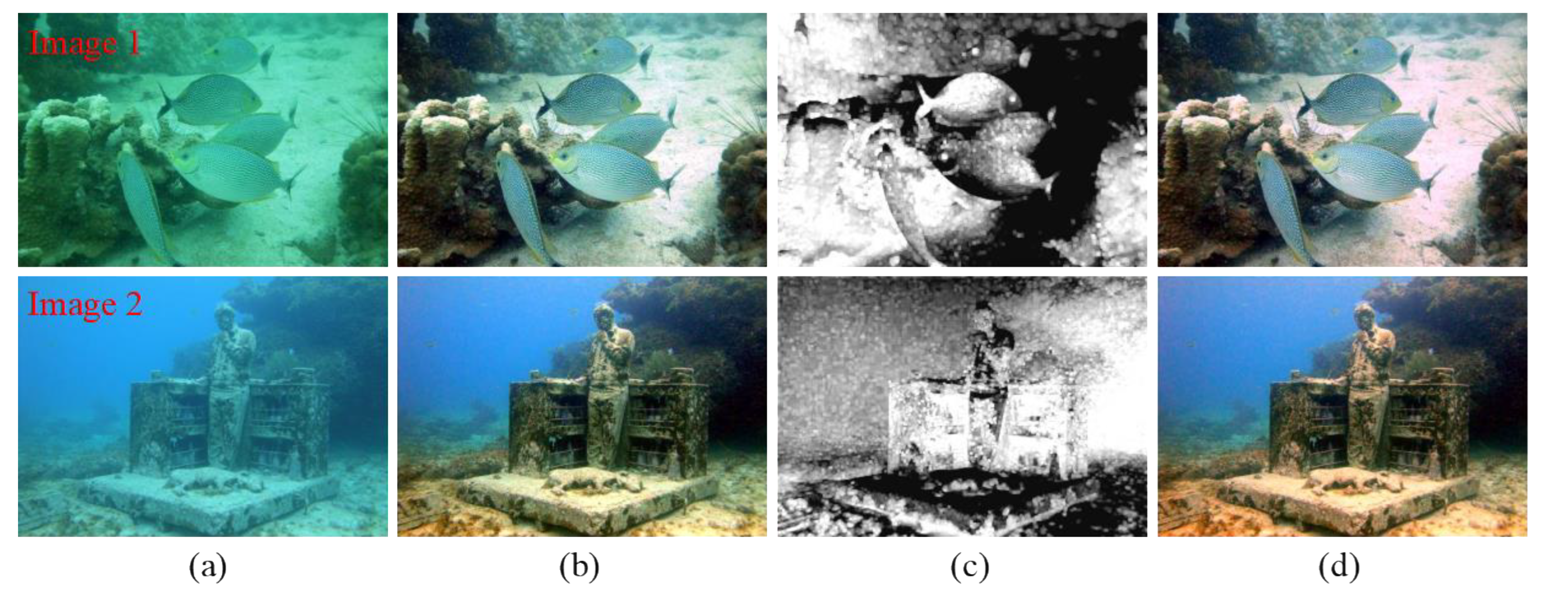
An automatic white balance algorithm of brightness and color balance is designed to correct the color distortion of underwater images and effectively restore the brightness and color of underwater images.
(3)
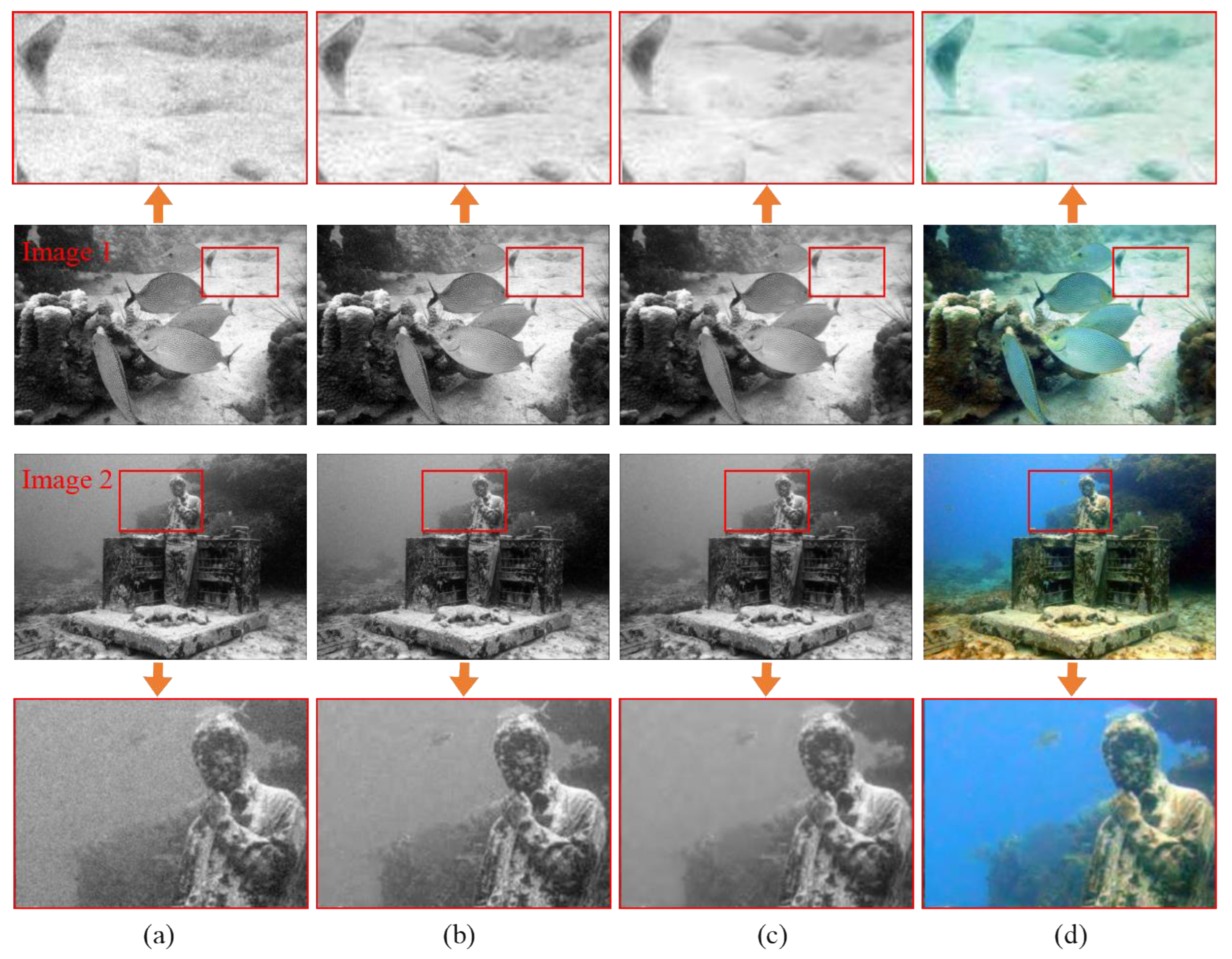
A noise suppression algorithm of heat conduction matrix in the wavelet domain is proposed, which can suppress the noise of the image and improve the contrast and edge details of the underwater image.
(4)
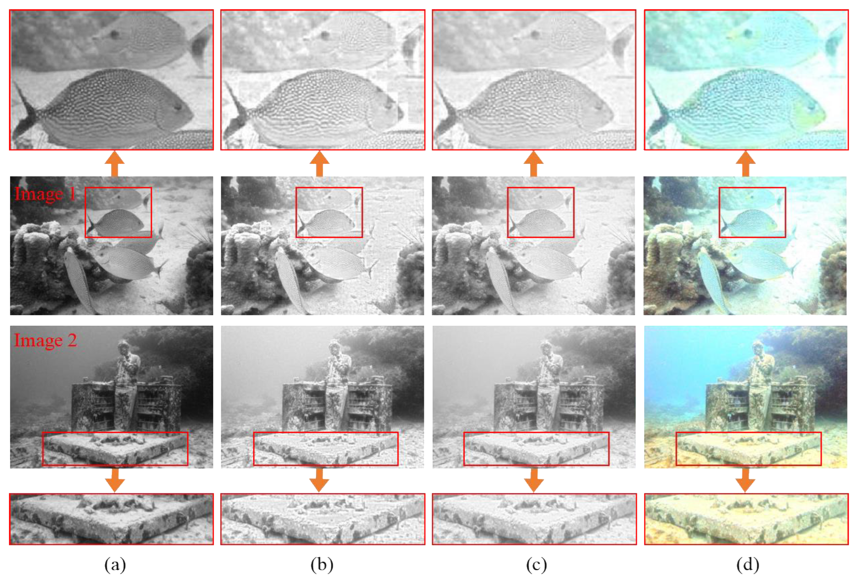
A block effect elimination algorithm in a compressed domain is proposed, which can eliminate the block effect in the process of image enhancement and balance the bright and dark areas in the image.
The structure of this paper is as follows: In Section 2, the main ideas and theoretical basis of the proposed method are described in detail. In Section 3, the research results are analyzed and discussed in terms of qualitative and quantitative comparisons and application tests. In Section 4, this paper’s work is summarized.

2. Models and Methods

In order to suppress the noise of the underwater color-cast image and eliminate the blocking effect in the process of image enhancement, an underwater color-cast image enhancement method based on noise suppression and block effect elimination is proposed in this paper. In this paper, it is mainly composed of four modules: brightness and color equalization, noise suppression, block effect elimination, and multi-scale image fusion. In the brightness and color equalization module, an automatic white balance algorithm for brightness and color balance is designed to correct the color distortion of underwater images. In the noise suppression module, a noise suppression algorithm based on the wavelet domain heat conduction matrix is proposed, and it suppresses the noise of the image and improves the contrast and edge details of the underwater image. In the block effect elimination module, a block effect elimination algorithm with a compressed domain boundary average is proposed, which eliminates the block effect in the enhancement process and balances the bright and dark regions in the image. In the multi-scale image fusion module, the image after color correction, noise suppression, and block effect elimination is used as the input of the multi-scale image fusion module, and it extracts dark channel weight, saturation weight, luminance weight, exposure weight, saliency weight, and chromatic weight corresponding to the input image, respectively. Then, calculate the Laplace value of the corresponding input image and the Gaussian value of the corresponding weight mapping, and finally perform multi-scale image fusion to obtain the enhanced underwater image. Figure 1 is the flowchart of the method proposed in this paper, and each part will be introduced in detail below.

2.1. Brightness and Color Equalization Module

In the complex and diverse underwater environment, due to the influence of different lighting and media attenuation characteristics, the image appears to have different degrees of color cast. In the method of this paper, firstly, the gray world white balance algorithm [16] is used to compensate for the image color distortion caused by the selective absorption of light by water bodies with different depths. The calculation formula of red channel compensation for underwater images is as follows:
Δ I r ( x ) = γ ( I ¯ g I ¯ r ) ( 1 I r ( x ) ) I g ( x ) ,
where Δ I r ( x ) is the compensation value of the image in the red channel; I r and I g are the channel values of the red channel and the green channel, respectively; I ¯ r and I ¯ g are the average values of the red channel and the green channel, respectively; and γ is the compensation coefficient of the red channel. Experiments show that when γ = 1 , it can adapt to different lighting environments and image-acquisition devices. In a color-rich image, the average gray value of its RGB three-channel components is assumed to be equal. At this time, the average gray value is divided by the average value of each channel to obtain the weight of each channel. Finally, each channel is multiplied by the weight to adjust the gray value of each channel. The calculation formula is as follows:
W R = K I ¯ r , W G = K I ¯ g , W B = K I ¯ b ,
R = W R I r G = W G I g B = W B I b ,
where K is the average gray value; W R , W G , and W B are the weights of RGB channels, respectively; and R , G , and B are the adjusted gray values of the RGB channels, respectively. As shown in Figure 2b, the underwater image processed by the gray world white balance algorithm can restore the color of the underwater image to a certain extent. However, in the case of serious color deviation, the obtained weight values are large, which will also lead to red artifacts and dark colors in the processed underwater images. Therefore, an automatic white balance algorithm for brightness and color balance is proposed. Firstly, the White Patch Retinex [27] is used to calculate the ambient light, then the dark channel prior algorithm is used to estimate the light transmittance, and then the white area in the image is calculated by the estimated light transmission model. Finally, the reference white point is used to adjust the underwater image and correct the color distortion of the image to maintain the color constancy of the underwater image. White Patch Retinex improves the color of the underwater images; that is, it can still retain the original color of the object when the external light source changes. The calculation formula is as follows:
I c ( x , y ) = G ( x , y ) R c ( x , y ) L c ,
where I c ( x , y ) is the final image, G ( x , y ) is the geometric size factor of image imaging, R c ( x , y ) is the reflection coefficient of the object to light, and L c is the intensity of ambient light. When G ( x , y ) = R c ( x , y ) = 1 , I c ( x , y ) = L c can be obtained. Therefore, the corresponding brightest pixel in the image is ambient light. Normally, the ambient light A c is constant and its calculation formula is as follows:
A c = L c = max L c ( x , y ) ,
According to the dark channel prior knowledge, we can obtain
D d a r k ( x , y ) = min ( x , y ) Ω ( x , y ) min ( r , g , b ) ( f ( x , y ) ) 0 ,
where Ω ( x , y ) is a neighborhood corresponding to the ( x , y ) pixels. For a small neighborhood, the light transmittance t 1 ( x , y ) can be expressed as
t 1 ( x , y ) = 1 min ( r , g , b ) ( g c ( x , y ) ) A c ,
where g c ( x , y ) represents the minimum value of the r , g , b channels in the g ( x , y ) neighborhood. The white area in the image is calculated by using the illumination transmission model. However, if there is a strong light source in the environment or a high saturation area in the image, the white area obtained by the illumination transmission model will have a false detection problem. Therefore, a threshold is set to eliminate the high saturation region:
T v ( x , y ) = 255 , 0 , t 1 ( x , y ) < t a v g ; g c ( x , y ) < K T o t h e r w i s e ,
where T v ( x , y ) is the binary image after the threshold transformation of the corresponding white area, and K T is a transformation threshold set in this paper. w and h are the width and height of the image, respectively, and t a v g is the average transmittance, as shown in Figure 2c.
t a v g = 1 w × h x = 0 w 1 y = 0 h 1 t 1 ( x , y ) .
After obtaining the white area, the mean value of the white area is used to calculate the correction gain of the three channels. We adjust the image by referring to the white dots, and the results are shown in Figure 2d. It can be seen that the image processed by the automatic white balance algorithm with brightness and color balance can correct the color distortion of the image, balance the brightness and color of the image, and maintain the color constancy of the underwater image.

2.2. Noise Suppression Module

In turbid or a large number of microbial waters, underwater images will not only appear blue–green bias but also produce a lot of noise. In order to suppress the noise of underwater images, a noise suppression algorithm for the heat conduction matrix in the wavelet domain is proposed. Firstly, the image after white balance preprocessing is converted from RGB color space to HSI color space, where the I component is shown in Figure 3a. Then, the I component is operated by a heat conduction matrix (HCM) [20] to increase the contrast and detail texture of the image and protect the edge information of the image. Heat conduction can be regarded as the process of heat transfer from high heat to low heat regions in solid or static fluid materials. Therefore, the color information of the pixels in the image can be compared with the temperature information in the system, and the pixels in the image can be regarded as a system. The level of color represents temperature, and the color transition between pixels is regarded as heat transfer. Based on this motivation, HCM is regarded as the heat conduction characteristic matrix on the I-channel image, which is used to check the difference between adjacent pixels. By performing 3 × 3 mask I component translations, we find that the calculation formula of HCM is
H C M c = k m a · A r e a L m ( P max P min ) ,
where H C M c is the heat conduction value of the central pixel P c of the mask, the A r e a value is the average surface area of the thermal path in the mask, and the L m value is the path length from the highest gray value to the lowest gray value in the mask. The thermal conductivity k m a represents the characteristics of the material. The thermal conductivity can be expressed as
k m a = P c 1 8 i = 1 8 P i 32 ,
where P c is the central pixel of the mask and P i is the adjacent pixel. By comparing the central pixel value with the adjacent pixel value, it is concluded that HCM is positive, negative, or zero. Here, the pixels of the image are adjusted by the mask ratio M a s k . The M a s k is calculated as follows:
M a s k = P c 1 9 i = 1 9 P i ,
As shown in Figure 3b, the pixel structure of the image is adjusted by the above operation, which improves the contrast and detail texture of the underwater image and also retains the edge information of the image. For the noise in the image, this paper performs multi-scale soft threshold denoising on the I component in the wavelet domain to suppress the noise of the underwater image. High-pass and low-pass filters are used in this paper to enable wavelet decomposition. In each level, the following threshold formula is applied to the wavelet coefficients:
W T i , j = W T i , j T i , j W T i , j > T i , j W T i , j + T i , j W T i , j < T i , j 0 W T i , j < T i , j ,
W T i , j = λ · W T i , j ,
where i is the wavelet scale coefficient, j = 1 , 2 , 3 ( HH , HL , LH ) , T i , j is the threshold, and λ is the enhancement coefficient. Then, calculate the inverse wavelet transform and reconstruct the wavelet coefficients, and finally return to the spatial domain through the inverse Fourier transform, and take the exponent to obtain the denoised image. The result is shown in Figure 3c. The image finally converted into RGB space is shown in Figure 3d. It can be seen that the whole image is smoother, the noise of the image is suppressed, and the contrast and edge details of the underwater image are improved.

2.3. Blocking Effect Elimination Module

In the process of image enhancement, the improvement of image contrast is often involved because it is directly related to the clarity of details. The common method is to increase the visibility of the texture details and other features of the image by amplifying the local intensity in the image. However, these methods are completed in the spatial domain, thus increasing the consumption of computing resources. In order to reduce the computational complexity and data storage requirements, more and more images are represented in compressed format. Therefore, this paper enhances underwater images in the compressed domain to reduce the complexity of various transformations in the spatial domain. However, the main problem of processing underwater images in the compressed domain is that the independent processing of blocks leads to block effects. This effect is more obvious in the region where the brightness value changes significantly, especially near the edge where the brightness value changes sharply. In order to eliminate the block effect generated in the process of image enhancement, a block effect elimination algorithm based on compressed domain boundary averaging is proposed. Firstly, the underwater image after white balance preprocessing is converted from RGB color space to YCbCr color space, where the Y component is shown in Figure 4a, and then the discrete cosine transform operation is performed on the Y component [21]. Using the idea of image block and classification, assuming that the two-dimensional image is x ( m , n ) , 0 m N 1 , 0 n N 1 , the discrete cosine transform coefficient of an image is obtained as
C ( k , l ) = 2 N a ( k ) m = 0 N 1 n = 0 N 1 x ( m , n ) × cos ( 2 m + 1 ) k π 2 N cos ( 2 n + 1 ) l π 2 N , 0 k , l N 1 ,
where ( k , l ) is the position of the discrete cosine transform coefficients and ( m , n ) is the position of the pixel in the original image. Because of the high computational complexity of the discrete cosine transformations, it is usually necessary to block the image to improve the efficiency of the transformation. For the selection of sub-block size, the larger the sub-block, the greater the computational complexity of the algorithm. After compromise, N is usually 8.
a ( k ) = { 1 2 , k = 0 1 , k 0 .
As shown in Figure 4b, the contrast of the image is enhanced after the discrete cosine transform operation. However, the characteristics of inter-band frequency change and inter-block coefficient change are not fully considered while enhancing the details of the dark area of the image, which often leads to blockiness in the image. Therefore, a block effect elimination algorithm based on boundary average in compressed domain is proposed. Let the sub-image size be 8 × 8, and L b a and R b a are horizontally adjacent sub-images filtered by local homomorphism. The blocking effect of horizontally adjacent sub-images is removed by averaging the adjacent boundary pixels of L b a and R b a , and its expression is as follows:
L b a ( m , n ) = i = 0 n 0 L ( m , n 1 ) + i = 0 n 0 1 R ( m , i ) N 0 m 7 , n = 7 R b a ( m , n ) = i = 0 n 0 1 L ( m , 7 i ) + i = 0 n 0 R ( m , n + i ) N 0 m 7 , n = 0 ,
where the template size is 1 × N , N = 2 n 0 + 1 , and n 0 is an integer ( 1 m 7 ). At the same time, let U b a and D b a be adjacent sub-images with local homomorphic filtering in a vertical direction. Similarly, the block effect of the vertical adjacent sub-images is removed by filtering the adjacent boundary pixels of U b a and D b a . The expression is as follows:
U b a ( m , n ) = i = 0 m 0 U ( m i , n ) + i = 0 m 0 1 D ( i , n ) M m = 7 , 0 n 7 D b a ( m , n ) = i = 0 m 0 1 U ( 7 i , n ) + i = 0 m 0 D ( m + i , n ) M m = 0 , 0 n 7 ,
where the template size is M × 1 , M = 2 m 0 + 1 , and m 0 is an integer ( 1 m 0 7 ). The result of eliminating the blocking effect by using the boundary average algorithm in compressed domain is shown in Figure 4c, and the image finally converted to RGB space is shown in Figure 4d. It can be seen that the blocking effect produced in the process of enhancing the image is eliminated, the bright and dark areas in the image are balanced, and the image quality is improved.

2.4. Multi-Scale Image Fusion Module

In order to obtain clear underwater images with color correction, noise suppression, and block effect elimination at the same time, this paper adopts a multi-scale image fusion method. This method can fuse multiple image information, complement different feature information in multiple images, and remove redundant unfavorable feature information, so as to increase the amount of image information and improve the robustness of the image enhancement method. Based on this, we first use the image after color correction, noise suppression, and block effect elimination as the input of the multi-scale image fusion module, then extract the dark channel weight, saturation weight, luminance weight, exposure weight, saliency weight, and chromatic weight corresponding to the input image [28], then calculate the Laplacian value corresponding to the input image and the Gaussian value of the corresponding weight mapping, and finally, carry out multi-scale fusion to obtain the enhanced underwater clear image.
The design of the weight measure needs to focus on the final effect of the output image, and the enhanced underwater image is closely related to the color appearance, so it is difficult to guarantee that the artifacts will not be introduced by simple pixel mixing. Therefore, a variety of weight maps are used in this paper during the fusion so that pixels with high weight values can be displayed more in the final image. The saliency weight aims to emphasize the salient object in the underwater scene and increase the contrast between the salient region and the shadow region, thereby improving the global contrast of the output image. The saliency weight map is shown in Figure 5e. However, the saliency map tends to have regions with high brightness values, which has certain limitations. Therefore, saturation weight and chromatic weight are introduced. By using high saturation region, the fusion algorithm in this paper can be more suitable for chromaticity information. At the same time, the ratio of input image to input image in color is adjusted by chromaticity weight, so as to control the image saturation gain. The expression of saturation weight is as follows:
W s a t k = 1 3 ( R k L k ) 2 + ( G k L k ) 2 + ( B k L k ) 2 ,
where W s a t k is the saturation weight; R k , G k , and B k are the R , G , and B three-channel images of the input image; L k is the brightness; and k is the k th input image. The saturation weight diagram is shown in Figure 5b. The expression of chromatic weight is as follows:
W C k = L k 1 + cos ( α H k + ϕ ) S k ,
where W C k is the color weight graph, H k is the hue of the input image, and S k is the saturation of the input image. Chromaticity weights are shown in Figure 5f.
Brightness weight refers to the distribution of larger pixel values for areas with higher brightness, while smaller pixel values are used for other areas, so as to minimize the color and contrast and realize the balance between them. The brightness weight diagram is shown in Figure 5c. However, its weight is not enough to enhance the contrast of underwater images. In order to solve this problem, the exposure weight is introduced to protect the mid-tones that may change under certain circumstances. Exposure weight is used to evaluate the degree of illumination of the target in the image. By weighting the pixels with high or low brightness, the brightness information of the image is improved, and the local contrast of the image remains unchanged. The calculation formula can be expressed as
W E k = exp [ I k ( x , y ) 0.5 ] 2 2 σ 2 ,
where W E k is the exposure weight and I k ( x , y ) is the value of the input image I k in the pixel position ( x , y ) . Set the standard deviation σ to 0.25. The exposure weight is shown in Figure 5d. In order to reflect the influence of selective absorption of light on the image to a certain extent, the dark channel weight is introduced, which can be more natural when dealing with over-illuminated areas. The dark channel weight can be expressed as
W D c k = min y Ω ( x ) ( min c r , g , b , τ { 1 , 2 , 3 } ( J τ c ( y ) ) ) ,
where W D c k is the dark channel weight, J c represents the color channel of the input image, Ω ( x ) represents the vicinity of the center of x , min y Ω ( x ) represents the minimum filter, and min c { r , g , b } represents the minimum value of the three color channels of R , G , and B . The effect after processing is shown in Figure 5a.
Finally, the Gaussian pyramid G l is used to decompose the normalized weight W ¯ k , and the input image is decomposed into the Laplacian pyramid L l by using the multi-scale image fusion algorithm. Then, the Laplacian input and the Gaussian normalized weight of each pyramid level are fused, and finally, the fused image is obtained by means of summing. The expression is
R l = k = 1 K G l W ¯ k L l ( I k ) ,
where R l represents the fused image, l represents the pyramid level, and k represents the number of input images.
Figure 5. The process of multi-scale image fusion module. (a) The dark channel weight map; (b) the saturation weight map; (c) the luminance weight map; (d) the exposure weight map; (e) the saliency weight map; (f) the chromaticity weight map.
Jmse 11 01226 g005
The processing results of multi-scale image fusion are shown in Figure 6. It can be seen that Figure 6c corrects the color cast of underwater images and effectively suppresses the noise and block effects of underwater images. It can be seen from the RGB histogram that the histogram distribution range of the image processed by the proposed method is wider and more uniform. It shows that the method of this paper can provide a theoretical basis for the research system of underwater image clarity.

3. Experimental Results and Discussion

In order to verify the effectiveness of the proposed method, qualitative comparison, quantitative comparison, and application tests are carried out. In the qualitative and quantitative comparison, in order to more fully demonstrate the effectiveness and robustness of the proposed algorithm, six existing classical underwater image enhancement techniques in different directions are compared, including UDCP [13], IBLA [14], WCID [11], and ARC [12] algorithms based on physical models, FUSION [17] algorithms based on non-physical models, and HWD [25] algorithms based on deep learning. Then, the advantages and disadvantages of each algorithm and the effect of processing underwater images are analyzed from qualitative and quantitative perspectives. Finally, Canny edge detection and feature matching (SIFT) are used to test the application, which shows that the proposed method has a certain kind of scalability. All the images in this paper are from the UIEBD [29] dataset. These datasets provide real underwater scenes, including real underwater color-biased images and underwater images with noise and block effects. In order to ensure that the comparison between the different algorithms is fair, the experiment in this paper is carried out in the environment of Matlab R2018 b. The hardware parameters of the computer are Windows 10 PC Inter (R) Core (TM) i7-9700 CPU 3.00 GHz.

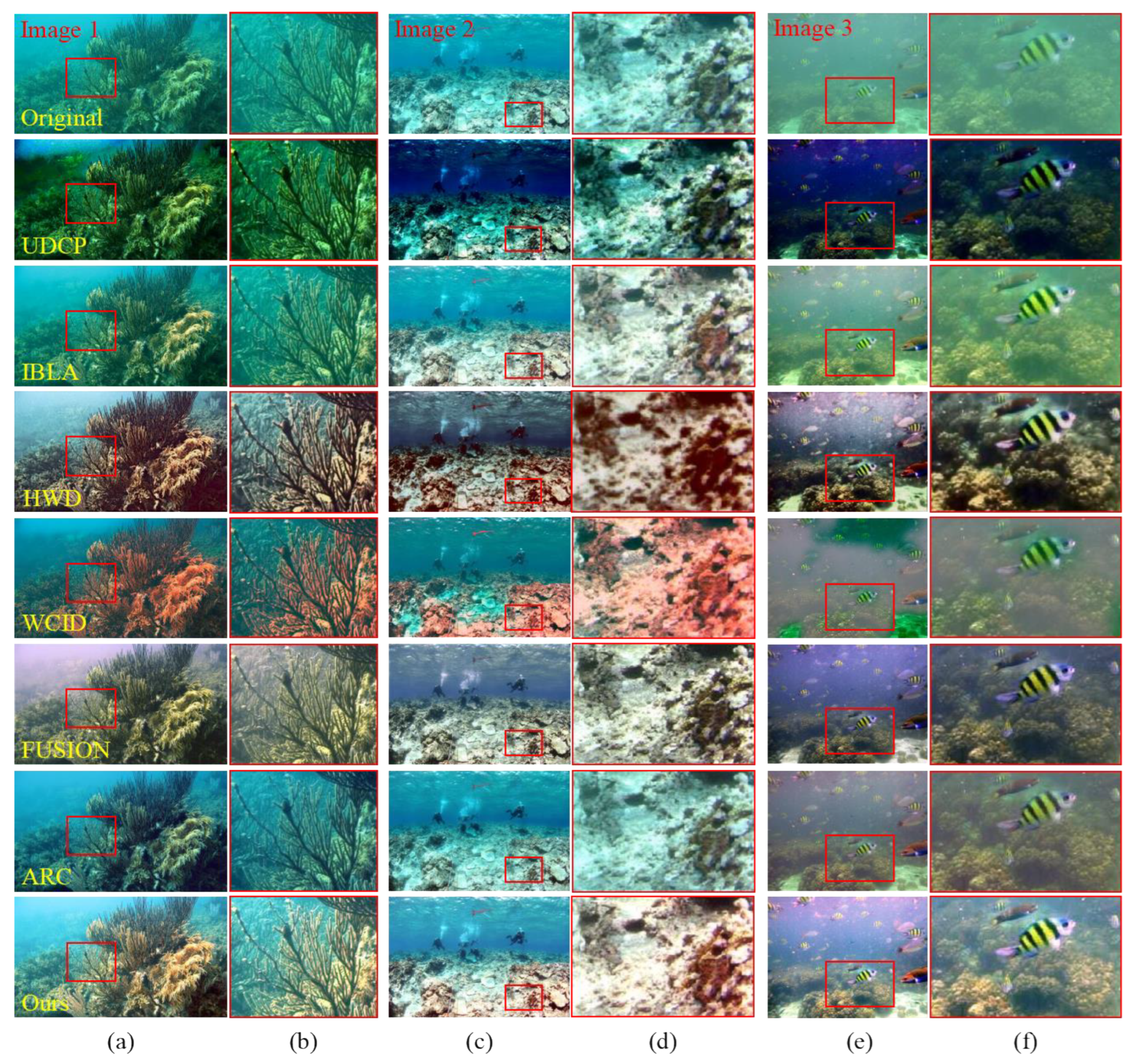
3.1. Qualitative Comparison

In order to verify the effectiveness of the method proposed in this paper, an underwater color-cast image with noise and block effects is selected for the experiment. At the same time, it is compared with the existing classic underwater image enhancement technology, and its color correction, contrast, and visibility are analyzed. Due to space limitations, only some of the experimental results are shown. The qualitative comparison results of different algorithms in a turquoise environment are shown in Figure 7. Figure 7a is the original underwater image, including underwater images with green and blue color casts. Figure 7b is the processing result of the UDCP algorithm. It can be seen that the underwater dark channel prior algorithm is not effective for processing underwater color-cast images, and more serious color casts are introduced. Among them, green color casts are introduced in Image 1 and Image 2, and blue color casts are introduced in Image 3 and Image 7, which may be an error in estimating transmittance. Figure 7c is the processing result of the IBLA algorithm. It can be seen that the method corrects the color deviation of blue and green to a certain extent, but the effect is not obvious. It does not show excellent results for underwater images, such as Image 1, Image 6, and Image 7, with serious color deviation. Figure 7d shows the processing result of the HWD algorithm, which can effectively correct the underwater color-cast image and show excellent effects, but it also reduces the contrast and has poor visibility. Figure 7e is the processing result of the WCID algorithm. It can be seen that there are obvious artifacts in the process of processing color-cast images, and at the same time, color casts are introduced, including red color casts in Image 1, blue color casts in Image 6, and blue color casts in Image 7. Figure 7f shows the processing result of the FUSION algorithm. It can be seen that this method restores the color of the underwater image, but all the images are gray and the image contrast is low. Figure 7g shows the processing result of the ARC algorithm, which can correct the green color shift, but the effect on the blue color shift correction is not obvious, and the contrast is not high. Figure 7h is the processing result of the method proposed in this paper. It can be seen that the method in this paper can effectively correct the blue–green bias, can restore the color of underwater images, and has high contrast and good visibility. It can be seen from the texture and edge details of the enhanced image that the method in this paper can suppress the noise of the underwater image and eliminate the block effect of the underwater image. Compared with the other six algorithms, the method proposed in this paper can effectively improve the quality of underwater degraded images, improve the visual effect, adapt to the underwater color-cast environment, and provide theoretical support for underwater visual environment perception technology.
The qualitative comparison results of different algorithms in natural shallow water and turbid environment are shown in Figure 8. Figure 8a is the original underwater image, which includes the light attenuation image and the turbid blurred image of natural shallow water. These images are not only blurry but also contain a lot of noise, which makes the whole image look very rough. Figure 8b is the processing result of the UDCP algorithm. It can be seen that the blue color bias is introduced in Image 3, the green color bias is introduced in Image 5 and Image 7, and the red color bias is introduced in Image 6, and the overall contrast of all images is low. Figure 8c shows the processing results of the IBLA algorithm. This method can improve the color of natural shallow water and turbid blurred underwater images, but the effect is not obvious and the contrast is low. Figure 8d is the processing result of the HWD algorithm. It can be seen that this method can effectively clear the turbidity of the image, but the contrast is low. Figure 8e is the processing result of the WCID algorithm. Similarly, the image processed by the algorithm also introduces artifacts. Figure 8f is the processing result of the FUSION algorithm. This method shows good results in dealing with natural shallow water and turbid blurred underwater images, but the contrast is low. Figure 8g is the processing result of the ARC algorithm. The processing effect of this method is not particularly obvious, and it is easy to introduce a little red color bias. Figure 8h shows the processing results of the method proposed in this paper. It can be seen that this method can improve the contrast and visibility of natural shallow water images. It can also effectively eliminate blur and improve the clarity of underwater images for turbid and blurred underwater images. It shows that the proposed method can correct the color distortion of the underwater image, effectively restore the brightness and color of the underwater image, improve the contrast and edge detail information of the underwater image, and balance the bright and dark areas in the image.
Figure 9 shows the comparison of the detail enhancement capabilities of different algorithms in different color and turbid water environments. The original image, the processing results of the UDCP algorithm, the processing results of the IBLA algorithm, the processing results of the HWD algorithm, the processing results of the WCID algorithm, the processing results of the FUSION algorithm, the processing results of the ARC algorithm, and the processing results of this method are listed from top to bottom. It can be seen from the local enlarged region that the underwater image obtained using this method has better contrast and clearer texture, which is obviously superior to other algorithms in terms of its quality. For the turbid and blurred underwater environment, the noise is more complex, and it will also lead to more obvious block effects. The method in this paper also has better performance in processing image details and can effectively eliminate its noise and block effects. It can be seen from Figure 9 that the method in this paper has a higher contrast and better visibility, and the image’s texture is clearer. Therefore, it also shows that the method proposed in this paper can be well adapted to the underwater environment with severe color deviation and turbidity.

3.2. Quantitative Comparison

Through qualitative comparison, it can be seen that the proposed method has a good enhancement effect in different underwater environments. In order to avoid the deviation of qualitative comparison, the quality of underwater image restoration using this method will be objectively evaluated on the basis of the image’s information, clarity, and comprehensive effects. Information entropy (IE) [30], spatial frequency (SF) [31], average gradient (AVG) [32], underwater color image quality evaluation index (UCIQE) [33], local contrast quality index (PCQI), and underwater image color metrics (UIQM) are used to evaluate the image. The information entropy (IE) reflects the average information level of the image. In general, the larger the value, the richer the image’s information and the higher the image’s fidelity. For an image, assuming that p i represents the proportion of the pixel gray value i , the unary gray entropy is defined as
IE = i = 0 255 p i log 2 p i ,
where p i is the probability of a certain gray level distribution in the image obtained from the gray level histogram.
Spatial frequency (SF) is used to evaluate the effect of underwater image color restoration, which describes the spatial change in the image’s value. The larger the value, the richer the color of the restored image and the better the effect of the fused edge. This can be defined as
SF = 1 M × N i = 1 M j = 2 N [ I i , j I i , j 1 ] 2 + 1 M × N j = 1 M i = 2 N [ I i , j I i 1 , j ] 2 ,
where M and N represent the width and height of the image, and I ( i , j ) represents the pixel value at point ( i , j ) in the image.
The average gradient (AG) reflects the change rate of image details and indicates the clarity of the image. The average gradient can be described as
AG = 1 ( M 1 ) ( N 1 ) i = 1 M 1 j = 1 N 1 ( I ( i , j ) I ( i + 1 , j ) ) 2 + ( I ( i , j ) I ( i , j + 1 ) ) 2 2 ,
The underwater color image quality evaluation index (UCIQE) is a linear combination of the chromaticity, saturation, and contrast of the image, which is mainly used to quantify the image degradation caused by non-uniform illumination, color deviation, blurring, and low underwater image contrast. The calculation method of the index is
UCIQE = a 1 × σ c + a 2 × c o n l + a 3 × μ s ,
where σ c represents the standard deviation of chromaticity, which has a good correlation with human perception, c o n l represents the contrast of brightness, and μ s represents the average saturation. While a 1 , a 2 , and a 3 are constants, which, respectively, correspond to the weights of the linear combination of the three components. Generally, the three weight coefficients are set to 0.4680, 0.2745, and 0.2576, respectively.
The local contrast quality index (PCQI) is a general index used to evaluate the image contrast, and the larger the value, the more appropriate the contrast of the corresponding image.
The underwater image color metric (UIQM) is used to evaluate the effect of underwater image color restoration. The larger the value, the richer the color of the restored image. It can be defined as
UIQM = c 1 × UICM + c 2 × UISM + c 3 × UIConM ,
where UICM represents the measurement of image color, UISM represents the measurement of image clarity, and UIConM represents the measurement of image contrast. Generally, the values of c 1 , c 2 , and c 3 are 0.0282, 0.2953, and 3.5753, respectively.
Due to space limitations, this paper only shows some experimental results. Seven representative color-cast images and seven images in natural shallow water and turbid environment were randomly selected from the UIEBD dataset. By calculating the information entropy (IE), spatial frequency (SF), average gradient (AVG), underwater color image quality evaluation index (UCIQE), local contrast quality index (PCQI), and underwater image color measurement index (UIQM) of each image, the six indexes are evaluated, and then the comparative analysis is carried out to evaluate the advantages and disadvantages of each algorithm. Table 1 is the quantitative comparison result of underwater color-cast images, and the value of coarsening in the table is the optimal value of the corresponding algorithm. As shown in Table 1, the method in this paper is superior to the other six classical algorithms known as information entropy (IE), spatial frequency (SF), average gradient (AG), and comprehensive effect measure (UCIQE). It shows that the enhanced underwater image is rich in information, high in clarity, closer to the natural scene, and has a better visual effect. The method in this paper is also superior to other algorithms such as the local contrast quality index (PCQI) and underwater image color metric (UIQM), indicating that the image enhanced by this method has rich color and high contrast. It also shows that the method in this paper can correct the color distortion of underwater images and effectively restore the brightness and color of underwater images.
Table 2 is the quantitative comparison results of natural shallow water and turbid environments. These images of natural shallow water and turbid environments are not only blurry but also contain a lot of noise. It can be seen from Table 2 that the results of this method on the four evaluation indicators are significantly better than other algorithms. It can be seen from the two indicators of information entropy and average gradient that this method can suppress the noise of the image and improve the contrast and edge detail information of the underwater image. From the two indicators of spatial frequency and underwater color image quality evaluation, it can be seen that the method in this paper eliminates the block effect of the image and balances the bright and dark regions in the image. Specifically, the images after color correction, noise suppression, and block effect elimination can be effectively adapted to various underwater image distortion scenes after multi-scale image fusion.

3.3. Application Test

In order to further prove the scalability of the method in this paper, application tests such as edge detection and feature point matching are carried out. Canny edge detection and scale-invariant feature transform (SIFT) [34] are used to test the edge detection and feature point matching of underwater images before and after restoration. The test results are shown in Figure 10 and Figure 11. The higher the number of edges and the higher the number of matching feature points, the clearer the image’s texture features and the wider its scalability. The restored image in Figure 10 has more edges than the original image, and the number of feature-matching points of the restored underwater image in Figure 11 is significantly more than that of the original underwater image. This also shows that the image processed by the method proposed in this paper has more texture details, and the clarity of the image is significantly improved. From the above analysis, it can also be concluded that the method in this paper can not only correct the color deviation of the image but also eliminate its noise and block effect, which has wide practical application value.

4. Conclusions

An underwater color-cast image enhancement method based on noise suppression and block effect elimination is proposed, and it can effectively correct the underwater color-cast image, suppress noise, eliminate block effects, and provide theoretical support to underwater visual environment perception technology. The main conclusion of this method is that an automatic white balance algorithm with brightness and color balance is designed to correct the color distortion of underwater images and effectively restore the brightness and color of underwater images. A noise suppression algorithm for a heat conduction matrix in the wavelet domain is proposed to eliminate image noise and improve the contrast and edge detail information of underwater images. A block effect elimination algorithm based on a compressed domain boundary average is proposed, and it eliminates the block effects during the enhancement process and balances the image’s bright and dark regions. The results of qualitative and quantitative evaluation and application test show that the proposed method has obvious advantages. They also show that it can effectively correct the underwater color-cast image, suppress its noise and block effects, and significantly increase its contrast and information. The results show that the proposed method has important practical value in the field of underwater visual environment perception. However, the method based on image enhancement often ignores the physical characteristics of underwater light propagation. Therefore, in future work, we will focus on the influence of underwater physical parameters on underwater image enhancement. This research can provide a theoretical basis for the construction of an underwater imaging model.

Author Contributions

Conceptualization, Y.N. and Y.-D.P.; Methodology, Y.N. and J.Y.; Software, Y.N. and Y.-P.J.; Validation, Y.N. and Y.-P.J.; Formal analysis, Y.-D.P. and Y.-P.J.; Investigation, Y.N.; Data curation, Y.N.; Writing—original draft preparation, Y.N. and Y.-D.P.; Writing—review and editing, Y.N. and Y.-D.P.; Visualization, J.Y.; Supervision, Y.-D.P.; Project administration, Y.-D.P. and Y.-P.J. All authors have read and agreed to the published version of the manuscript.

Funding

This work was supported by the Special Project for the Construction of Innovative Provinces in Hunan (Grant No. 2020GK1021), the Construction Project for Innovative Provinces in Hunan (Grant No. 2020SK2025) and the National Key Research and Development Program of China (Grant No. 2022YFC2805904).

Institutional Review Board Statement

Not applicable.

Informed Consent Statement

Not applicable.

Data Availability Statement

The data underlying the results presented in this paper are not publicly available at this time but may be obtained from the authors upon reasonable request.

Acknowledgments

The authors would like to thank the editor and the anonymous reviewers for their valuable comments.

Conflicts of Interest

The authors declare no conflict of interest.

References

  1. Li, Z.; Chao, X.; Hameed, I.; Li, J.; Zhao, W.; Jing, X. Biomimetic omnidirectional multi-tail underwater robot. Mech. Syst. Signal Process. 2022, 173, 109056. [Google Scholar] [CrossRef]
  2. Yurugi, M.; Shimanokami, M.; Nagai, T.; Shintake, J.; Ikemoto, Y. Cartilage structure increases swimming efficiency of underwater robots. Sci. Rep. 2021, 11, 11288. [Google Scholar] [CrossRef] [PubMed]
  3. Yao, P.; Sui, X.; Liu, Y.; Zhao, Z. Vision-based environment perception and autonomous obstacle avoidance for unmanned underwater vehicle. Appl. Ocean Res. 2023, 134, 103510. [Google Scholar] [CrossRef]
  4. Huang, H.; Tang, Q.; Li, J.; Zhang, W.; Bao, X.; Zhu, H.; Wang, G. A review on underwater autonomous environmental perception and target grasp, the challenge of robotic organism capture. Ocean Eng. 2020, 195, 106644. [Google Scholar] [CrossRef]
  5. Zhang, Y.; Zhou, L.; Li, H.; Zhu, J.; Du, W. Marine Application Evaluation of Monocular SLAM for Underwater Robots. Sensors 2022, 22, 4657. [Google Scholar] [CrossRef]
  6. Chen, Q.; Zhang, Z.; Li, G. Underwater Image Enhancement Based on Color Balance and Multi-Scale Fusion. IEEE Photonics J. 2022, 14, 3963010. [Google Scholar] [CrossRef]
  7. Muniraj, M.; Dhandapani, V. Underwater image enhancement by modified color correction and adaptive Look-Up-Table with edge-preserving filter. Signal Process. Image Commun. 2023, 113, 116939. [Google Scholar] [CrossRef]
  8. Hu, J.; Jiang, Q.; Cong, R.; Gao, W.; Shao, F. Two-branch deep neural network for underwater image enhancement in HSV color space. IEEE Signal Process. Lett. 2021, 28, 2152–2156. [Google Scholar] [CrossRef]
  9. Peng, Y.T.; Cao, K.; Cosman, P.C. Generalization of the dark channel prior for single image restoration. IEEE Trans. Image Process. 2018, 27, 2856–2868. [Google Scholar] [CrossRef]
  10. Chiang, J.Y.; Chen, Y.C. Underwater image enhancement by wavelength compensation and dehazing. IEEE Trans. Image Process. 2011, 21, 1756–1769. [Google Scholar] [CrossRef]
  11. Jayasree, M.S.; Thavaseelan, G.; Scholar, P.G. Underwater color image enhancement using wavelength compensation and dehazing. Int. J. Comput. Sci. Eng. Commun. 2014, 2, 389–393. [Google Scholar]
  12. Galdran, A.; Pardo, D.; Picón, A.; Alvarez-Gila, A. Automatic red-channel underwater image restoration. J. Vis. Commun. Image Represent. 2015, 26, 132–145. [Google Scholar] [CrossRef] [Green Version]
  13. Drews, P.; Nascimento, E.; Moraes, F.; Botelho, S.; Campos, M. Transmission estimation in underwater single images. In Proceedings of the IEEE International Conference on Computer Vision Workshops, Sydney, Australia, 2–8 December 2013; pp. 825–830. [Google Scholar] [CrossRef]
  14. Peng, Y.T.; Cosman, P.C. Underwater image restoration based on image blurriness and light absorption. IEEE Trans. Image Process. 2017, 26, 1579–1594. [Google Scholar] [CrossRef]
  15. Wang, Y.; Song, W.; Fortino, G.; Qi, L.Z.; Zhang, W.; Liotta, A. An experimental-based review of image enhancement and image restoration methods for underwater imaging. IEEE Access 2019, 7, 140233–140251. [Google Scholar] [CrossRef]
  16. Ghani AS, A.; Isa NA, M. Automatic system for improving underwater image contrast and color through recursive adaptive histogram modification. Comput. Electron. Agric. 2017, 141, 181–195. [Google Scholar] [CrossRef] [Green Version]
  17. Ancuti, C.O.; Ancuti, C.; De Vleeschouwer, C.; Bekaert, P. Color balance and fusion for underwater image enhancement. IEEE Trans. Image Process. 2017, 27, 379–393. [Google Scholar] [CrossRef] [Green Version]
  18. Huang, D.; Wang, Y.; Song, W.; Sequeira, J.; Mavromatis, S. Shallow-water image enhancement using relative global histogram stretching based on adaptive parameter acquisition. In MultiMedia Modeling: Proceedings of the 24th International Conference, MMM 2018, Bangkok, Thailand, 5–7 February 2018; Proceedings, Part I 24; Springer International Publishing: Berlin/Heidelberg, Germany, 2018; pp. 453–465. [Google Scholar] [CrossRef] [Green Version]
  19. Hou, G.; Pan, Z.; Huang, B.; Wang, G.; Luan, X. Hue preserving-based approach for underwater colour image enhancement. IET Image Process. 2018, 12, 292–298. [Google Scholar] [CrossRef]
  20. Katırcıoğlu, F. Colour image enhancement with brightness preservation and edge sharpening using a heat conduction matrix. IET Image Process. 2020, 14, 3202–3214. [Google Scholar] [CrossRef]
  21. Mukherjee, J.; Mitra, S.K. Enhancement of color images by scaling the DCT coefficients. IEEE Trans. Image Process. 2008, 17, 1783–1794. [Google Scholar] [CrossRef] [PubMed]
  22. Bai, L.; Zhang, W.; Pan, X.; Zhao, C. Underwater image enhancement based on global and local equalization of histogram and dual-image multi-scale fusion. IEEE Access 2020, 8, 128973–128990. [Google Scholar] [CrossRef]
  23. Li, C.; Guo, J.; Guo, C. Emerging from water: Underwater image color correction based on weakly supervised color transfer. IEEE Signal Process. Lett. 2018, 25, 323–327. [Google Scholar] [CrossRef] [Green Version]
  24. Yu, X.; Qu, Y.; Hong, M. Underwater-GAN: Underwater image restoration via conditional generative adversarial network. In Pattern Recognition and Information Forensics: Proceedings of the ICPR 2018 International Workshops, CVAUI, IWCF, and MIPPSNA, Beijing, China, 20–24 August 2018; Revised Selected Papers 24; Springer International Publishing: Berlin/Heidelberg, Germany, 2019; pp. 66–75. [Google Scholar] [CrossRef]
  25. Pan, P.; Yuan, F.; Cheng, E. Underwater image de-scattering and enhancing using dehazenet and HWD. J. Mar. Sci. Technol. 2018, 26, 6. [Google Scholar] [CrossRef]
  26. Anwar, S.; Li, C. Diving deeper into underwater image enhancement: A survey. Signal Process. Image Commun. 2020, 89, 115978. [Google Scholar] [CrossRef]
  27. Chung, Y.L.; Chung, H.Y.; Chen, Y.S. A Study of Single Image Haze Removal Using a Novel White-Patch RetinexBased Improved Dark Channel Prior Algorithm. Intell. Autom. Soft Comput. 2020, 26, 367–383. [Google Scholar]
  28. Song, H.; Wang, R. Underwater image enhancement based on multi-scale fusion and global stretching of dual-model. Mathematics 2021, 9, 595. [Google Scholar] [CrossRef]
  29. Li, C.; Guo, C.; Ren, W.; Cong, R.; Hou, J.; Kwong, S.; Tao, D. An underwater image enhancement benchmark dataset and beyond. IEEE Trans. Image Process. 2019, 29, 4376–4389. [Google Scholar] [CrossRef] [Green Version]
  30. Zhou, J.; Zhang, D.; Zou, P.; Zhang, W.; Zhang, W. Retinex-based laplacian pyramid method for image defogging. IEEE Access 2019, 7, 122459–122472. [Google Scholar] [CrossRef]
  31. Eskicioglu, A.M.; Fisher, P.S. Image quality measures and their performance. IEEE Trans. Commun. 1995, 43, 2959–2965. [Google Scholar] [CrossRef] [Green Version]
  32. Zhang, L.; Zhang, L.; Mou, X.; Zhang, D. FSIM: A feature similarity index for image quality assessment. IEEE Trans. Image Process. 2011, 20, 2378–2386. [Google Scholar] [CrossRef] [Green Version]
  33. Yang, M.; Sowmya, A. An underwater color image quality evaluation metric. IEEE Trans. Image Process. 2015, 24, 6062–6071. [Google Scholar] [CrossRef]
  34. Zhang, W. Combination of SIFT and Canny edge detection for registration between SAR and optical images. IEEE Geosci. Remote Sens. Lett. 2020, 19, 4007205. [Google Scholar] [CrossRef]
Figure 1. The flowchart of the method proposed in this paper.
Jmse 11 01226 g001
Figure 2. The process of brightness and color equalization module. (a) Original underwater image; (b) image processed by the gray world white balance algorithm; (c) the average transmittance chart; (d) image processed by an automatic white balance algorithm with brightness and color balance.
Jmse 11 01226 g002
Figure 3. The process of noise suppression module. (a) I component in HSI color space; (b) the result of heat conduction matrix processing; (c) the result of noise suppression algorithm using wavelet domain heat conduction matrix; (d) the image converted to RGB space.
Jmse 11 01226 g003
Figure 4. The process of block effect elimination module. (a) Y component in YCbCr color space; (b) the result of discrete cosine transform; (c) the result of the block effect elimination algorithm using the compressed domain boundary average; (d) the image converted to RGB space.
Jmse 11 01226 g004
Figure 6. The processing results of multi-scale image fusion module. (a) Original underwater image; (b) RGB histogram of the original underwater image; (c) the enhanced image for our proposed method; (d) RGB histogram of the enhanced image.
Jmse 11 01226 g006
Figure 7. Qualitative comparison results of different algorithms in turquoise water environment. (a) The original image; (b) the processing result of UDCP algorithm; (c) the processing result of IBLA algorithm; (d) the processing result of HWD algorithm; (e) the processing result of WCID algorithm; (f) the processing result of FUSION algorithm; (g) the processing result of ARC algorithm; (h) the processing result of this method.
Jmse 11 01226 g007
Figure 8. Qualitative comparison results of different algorithms in natural shallow water and turbid environment. (a) The original image; (b) the processing result of UDCP algorithm; (c) the processing result of IBLA algorithm; (d) the processing result of HWD algorithm; (e) the processing result of WCID algorithm; (f) the processing result of FUSION algorithm; (g) the processing result of ARC algorithm; (h) the processing result of this method.
Jmse 11 01226 g008
Figure 9. Comparison of detail enhancement ability of different algorithms in different color cast and turbid water environments. (a,c,e) Three underwater images in different scenes, respectively; (b) the enlarged figure in the red box of (a); (d) the enlarged figure in the red box of (c); (f) the enlarged figure in the red box of (e).
Jmse 11 01226 g009
Figure 10. Canny edge detection results. (ad) The original underwater image and its Canny edge detection results; (eh) the images processed using this method and their Canny edge detection results.
Jmse 11 01226 g010
Figure 11. The test results of SIFT feature matching. (ad) The feature-matching test results of the original underwater image; (eh) the feature-matching test results of the images processed using this method.
Jmse 11 01226 g011
Table 1. Quantitative comparison results of underwater color-cast images.
ImageEvaluationOriginal ImageUDCPIBLAHWDWCIDFUSIONARCOurs
Image 1IE6.17307.07566.82057.67366.77097.61107.33867.8367
SF7.161118.934513.164121.432720.908718.489814.166824.5150
AVG4.01699.68247.068012.756711.333710.39187.815514.0663
UCIQE0.34120.52540.39200.57750.56380.54440.49550.6092
PCQI0.11550.92690.34921.46691.40551.02720.56061.7884
UIQM−1.08442.85370.19354.28224.19255.41523.18425.7959
Image 2IE6.92736.30467.50117.68306.87007.60207.45447.8081
SF7.17066.646212.489213.121311.899713.691011.592514.7812
AVG3.67843.21286.10607.02075.50166.66005.65047.5488
UCIQE0.47880.46970.57230.59310.57750.57530.58970.6377
PCQI0.16340.16550.47020.78840.55630.78700.54250.7300
UIQM0.38901.38712.04484.55293.18654.65083.61264.6494
Image 3IE7.27586.49487.62277.72486.84257.68807.43727.8066
SF9.098310.845213.788713.145914.204714.96239.593315.9068
AVG4.53164.90566.96297.18507.04747.30114.96498.2921
UCIQE0.51030.56790.55220.58700.58800.56040.56060.6115
PCQI0.23660.51750.48650.71150.63320.73090.34100.6950
UIQM1.28953.60312.62204.53012.14664.37122.48744.5686
Image 4IE6.40226.10456.78617.61696.29307.19796.98217.4177
SF9.658814.981811.758617.278517.097514.007911.391121.2587
AVG3.99175.60295.07147.95007.60115.94334.77479.9995
UCIQE0.45950.53860.51280.61530.54620.54720.54410.6460
PCQI0.20970.75270.31511.00900.82650.62620.35321.1339
UIQM−1.10120.9939−0.30453.41813.09883.18560.30893.8822
Image 5IE7.19777.16687.53797.65357.21887.68547.53047.9026
SF17.260222.699720.422821.733528.559325.597018.518730.1024
AVG7.830310.23539.651710.734812.835911.03878.803613.9104
UCIQE0.52270.62000.56670.61590.61820.55970.59810.6559
PCQI0.76171.86891.16571.84622.45842.09051.10662.4011
UIQM0.50722.92572.04243.76962.71254.73602.02394.7363
Image 6IE6.81827.13187.27587.70736.26527.66737.40537.7350
SF4.79546.46996.735110.44456.40328.84257.28289.6852
AVG2.43743.25863.50346.05343.25674.40113.76505.3092
UCIQE0.41900.52620.47400.59200.49800.53980.56910.6237
PCQI0.07050.15430.14610.29080.16100.35100.23780.5252
UIQM−1.15491.91360.34933.70682.18063.01211.71573.7351
Image 7IE6.78666.42237.24797.69956.49037.60137.33187.7558
SF6.22958.94928.571713.18019.146811.39368.248513.9449
AVG3.65794.78255.06537.62135.14886.53044.87707.8985
UCIQE0.46600.59550.53290.62480.52590.62220.60040.6729
PCQI0.12710.40790.25010.73530.32340.67480.28510.8334
UIQM0.08661.71851.14153.87963.14473.60381.93163.8761
AverageIE6.79736.67157.25607.67986.67877.57907.35437.7518
SF8.767712.789512.418615.762415.460015.283411.542018.5992
AVG4.30635.95436.20418.47467.53227.46665.80739.5750
UCIQE0.45680.54900.51470.60080.55970.56410.56540.6367
PCQI0.24060.68480.45470.97830.90920.89820.48951.1581
UIQM−0.15262.19941.15564.01992.95174.13922.18064.4634
Table 2. Quantitative comparison results of natural shallow water and turbid environment.
ImageEvaluationOriginal ImageUDCPIBLAHWDWCIDFUSIONARCOurs
Image 1IE6.94137.17887.65177.70436.86877.46587.57737.7702
SF16.550722.406123.740425.852624.954727.647521.726328.3122
AVG9.117912.250013.898615.179912.963814.782512.665716.0165
UCIQE0.47900.60170.59170.58430.54680.58310.56700.6063
PCQI0.81912.61841.73552.33452.31602.77811.61402.9782
UIQM4.11004.40315.14534.87514.68894.95295.17505.0115
Image 2IE6.18076.52376.94057.59776.58107.09647.02107.4781
SF7.599715.253711.159517.305912.334316.942411.403517.6959
AVG3.82777.27326.326510.43456.10238.60556.374210.4866
UCIQE0.43980.59850.53240.62820.52750.61690.57270.6361
PCQI0.14750.91040.31550.79850.60471.04530.46661.2467
UIQM1.97813.35523.52954.00382.87103.98874.11314.3789
Image 3IE7.72815.99217.60087.64627.44017.69107.66177.9219
SF11.079910.248711.923810.936613.375113.912512.827215.9482
AVG4.60154.23665.01695.02045.58865.58345.45386.6066
UCIQE0.60010.52730.61620.55250.64830.59500.59240.6054
PCQI0.66130.78000.99570.58610.96390.88250.81011.0562
UIQM1.54301.61922.51343.04063.27982.48632.59923.4429
Image 4IE6.64106.37657.18807.72226.50337.70306.91327.7449
SF3.953814.50045.20847.44976.010910.01834.23537.8849
AVG1.66434.62872.35924.20252.22324.53121.88664.0729
UCIQE0.41770.56880.48900.59420.48480.57100.48240.6073
PCQI0.03220.15370.06320.21540.09620.23280.04430.6421
UIQM−0.20321.84180.57543.08023.08372.68090.91803.1075
Image 5IE6.99845.87327.53647.68586.53057.42747.20027.7910
SF3.25203.48415.09705.62844.01745.27473.88866.0968
AVG1.88161.60213.08763.70662.27333.10482.25633.6260
UCIQE0.46760.50690.54590.53520.50550.55460.49370.5814
PCQI0.03880.07720.13360.15370.07390.13900.05270.1945
UIQM2.34803.22174.02814.13812.73233.89853.08454.0683
Image 6IE5.89456.66297.08737.70946.25807.58107.01007.7791
SF2.29385.27423.64737.25742.39875.89543.58096.5521
AVG1.37022.87642.35794.67051.30283.65262.22834.0897
UCIQE0.36830.53970.52670.59930.41100.60400.53340.6343
PCQI0.01390.10650.04750.13660.02880.13750.07330.2337
UIQM2.04764.45083.47624.38463.63593.90203.60015.2295
Image 7IE6.17596.79247.26147.70056.12137.59707.22777.8172
SF4.406610.92279.221212.57616.521013.29639.689313.4009
AVG2.38785.41694.87957.89703.22886.98825.30267.6241
UCIQE0.35620.53350.47540.57260.39000.58140.53140.5987
PCQI0.04470.36740.18890.48120.13990.55960.31560.6488
UIQM1.04812.20402.56374.51712.28034.78164.36554.8693
AverageIE6.65146.48577.32377.68096.61477.50887.23027.7575
SF7.019511.72719.999712.42959.944613.28399.621613.6987
AVG3.55015.46915.41807.30164.81186.74975.16687.5032
UCIQE0.44700.55380.53960.58090.50200.58660.53900.6099
PCQI0.25110.71620.49710.67230.60330.82500.48241.0000
UIQM1.83883.01373.11884.00563.22463.81303.40794.3011
Disclaimer/Publisher’s Note: The statements, opinions and data contained in all publications are solely those of the individual author(s) and contributor(s) and not of MDPI and/or the editor(s). MDPI and/or the editor(s) disclaim responsibility for any injury to people or property resulting from any ideas, methods, instructions or products referred to in the content.

