1. Introduction
UUVs (unmanned underwater vehicles) have recently been used for various purposes such as in military technology, resource exploration, and environmental monitoring. UUVs are being developed in various forms, depending on their purpose. UUVs can be classified into ROVs (remotely operated vehicles) and AUVs (autonomous underwater vehicles), depending on whether cables are attached. ROVs are underwater robots that can be remotely controlled, and are further classified into passive mobile types and active mobile types. A passive mobile ROV is called a TUV (towed underwater vehicle). It is connected to the ship by a towing cable and is moved by the towing force of the ship. Most TUVs have a torpedo type form. The AQS-24B of the United States is a TUV [
1]. Active mobile ROVs are driven by thrusters. The URI-L of Korea is an example of the active mobile ROV type [
2]. An AUV is an underwater robot that moves autonomously with an autonomous navigation algorithm. AUVs can be classified into cruising type and hovering type AUVs [
3,
4].
Cruising type AUVs are underwater vehicles that move along predetermined routes. These AUVs autonomously navigate based on pre-set routes and mission objectives, allowing them to collect data and perform environmental surveys at specific locations. Examples of cruising type AUVs include the Hugin Superior (Norway), Mbari Dorado (Canada), and Sea Otter MKII (Bremen, Germany). These vehicles are commonly used for exploring water depths and underwater terrains. Hovering type AUVs, on the other hand, are underwater vehicles designed to either remain stationary or maintain a fixed position at specific locations. These AUVs hover in a static state, enabling them to perform detailed survey tasks and environmental monitoring. The P-SURO II from Korea serves as an example of a hovering type AUV. Such vehicles are particularly useful for tasks such as studying marine ecosystems and assessing marine resources [
3,
4,
5,
6,
7]. Cruising type and hovering type AUVs are designed to serve different purposes and missions. They are employed in various underwater exploration and research activities, each catering to specific needs and objectives.
TUVs are used to explore large areas, and active mobile ROVs are used for precision exploration. A side scan sonar for obtaining a large area image is usually attached to a TUV. Since the TUV moves according to the speed of the towing vessel, it cannot be operated if the vessel is stationary or the speed is low. Therefore, TUVs do not have equipment that is useful at low speeds, such as optical cameras or forward looking sonars. If a TUV capable of active movement including stationary or low-speed operation is developed, various mission equipment can be mounted on one platform and used. In our research paper [
8], we proposed a novel TUV that features active stabilization and low-speed maneuvering capabilities. In paper [
8], we primarily discussed the hardware aspects of the new TUV. Furthermore, we conducted experiments in a 1-knot circulating water channel environment using a PID controller with a simplified feedforward gain, without incorporating the model. However, we encountered difficulties in effectively adapting to changing flow conditions solely through gain tuning. This highlighted the need for additional enhancements in our control approach.
We present in this paper a method for estimating the control model of a prototype of the novel TUV equipped with active stabilization and low-speed maneuvering capabilities, and propose a depth and posture control algorithm that incorporates the estimated model. The effectiveness of the proposed TUV and control algorithm was demonstrated through experiments conducted in a circulating water channel under various flow rate conditions. In this study, the novel TUV exhibited the ability to operate as an ROV during low-speed conditions and as a TUV during towing situations.
2. Model Estimation
Figure 1 is the layout of the novel towed underwater vehicle that is the subject of research in this paper. For towing the TUV, a towing cable is attached to the front, and four horizontal rudders and thrusters are arranged as shown in the figure for attitude control and depth control during towing operation. Additionally, when not towing, forward movement is possible through the propulsion thruster. Since this novel TUV has a vertical thruster and a vertical rudder for posture control, it can operate at a standstill or low speed and can be operated even in heavy currents of 5 knots or more. The rudder changes the drag and lift force according to the angle and the current speed. Therefore, it is not possible to control the posture and depth of the TUV in response to the changing current speed only with simple feedback control such as PID control. In order to respond to the changing current speed, we propose a feedback control based on the model of force generated by the rudder and thruster of the TUV. For this, model identification was performed for rudder and thruster.
For models estimating underwater robots, a force/torque (F/T) sensor is usually used to measure force and torque applied to underwater vehicles in environments with currents. However, the F/T sensor struggles to measure underwater vehicles with a large load due to its fragile structure. While utilizing a scaled-down model of the TUV enables the use of F/T sensors for model estimation, there is a potential issue of experimental errors caused by shape discrepancies and shape reduction due to the application of the model reduction.
In this paper, we propose a concept of a measuring device, as shown in
Figure 2, to measure the lift force and drag force of the TUV caused by the underwater flow velocity. The upper fixed part of the measurement device is connected to four links with rotary joints, and the lower end of the links is connected to the top four points of the TUV with spherical joints. In addition, an encoder for measuring the angle is attached to the upper rotary joint, and a loadcell is installed between each of the four links. By measuring the force with the loadcell and the angle with the encoder, the drag force and lift force caused by underwater flow can be calculated. Due to the need to measure the changing angles in response to the underwater flow, not all thrusters were activated.
The drag and lift of the TUV can be calculated by Equations (1) and (2) with the angle (
ϴ) of the rotary joint that is changed by the influence of the current and the force (
FT) measured by the tensile and compression sensor.
Here, Fb is the buoyancy of the TUV, Fω is the weight of the TUV, Fl is the TUV lift force created by the flow velocity, and Fd is the drag force of the body shape created by the flow velocity.
Figure 3 shows the experimental setup used to estimate the model of the towed underwater vehicle (TUV) in a circulating water channel, which generated a flow velocity for the experiments. Using this experimental setup, we estimated the lift force and drag force of the TUV caused by the underwater flow velocity.
Figure 4 displays the measured lift force for the angle change of the bow rudder and the stern rudder when the current speed is 1 knots. Applying this result, we define the drag force generated by the angle (
δ) and the current velocity (
v) as in Equation (3), where
ρ is density of fluid,
CD is drag coefficient and S is area of the rudder [
9].
By transforming Equation (3), we can derive Equation (4) for the angle of the rudder to generate a force (
Frudder) under the current speed, where
C is the value calculated as
ρCDS based on the results shown in
Figure 4.
The experimentally derived parameters
C are presented in
Table 1.
The thruster model was derived from the vertical thruster and propulsion thruster models based on the test analysis provided by the manufacturer.
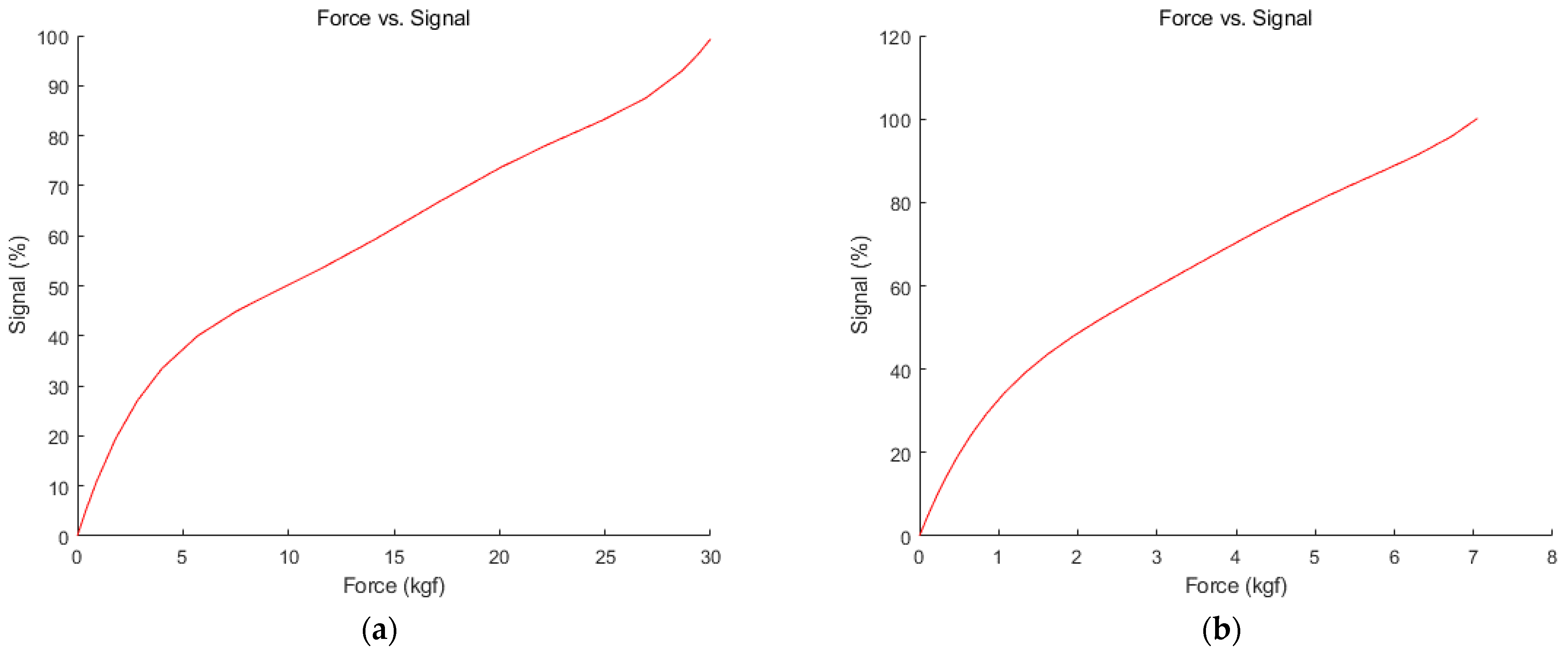
Figure 5 shows the relationship between the thruster output force and the thruster command input. The relationship between the thruster output force and the thruster input command input can be expressed as a polynomial as in Equation (5).
Signal (%) represents the speed command input signal for the thruster. It is expressed as a percentage, where 100% corresponds to the maximum speed output of the thruster. p1, p2, p3, p4, p5, p6 are model parameters that determine the relationship between the thruster’s output force and the thruster command input. F represents the thruster’s output force, which indicates the actual force generated by the thruster’s operation. Therefore, Equation (5) represents a polynomial expression that determines the thruster’s command input signal required to generate the output force F of the thruster, using the coefficients p1 to p6.
Additionally, according to the current velocity, the body of the TUV generates drag and lift force. The drag and lift force can be expressed as Equations (6) and (7).
where
v is the current velocity,
CDb is the drag coefficient, and
CLb is the lift coefficient. These equations provide a way to estimate the drag and lift forces based on the current velocity, allowing us to understand the TUV’s motion characteristics. In order for the TUV to maintain depth, it needs to actuate a force that counteracts the lift force (
FLb) generated according to the velocity. This force can be applied to the feedforward term of the controller.
In addition, the drag force (
FDb) generates a lift force (
FL_Db) according to the traction position of the surface vessel as shown in Equations (8) and (9).
h is the height at which the cable is towed from the water surface. d and lcable are the depth of the TUV and the length of the towing cable unwound.
As a result, the total lift force of TUV’s body generated by the current velocity is as Equation (10).
For the TUV to maintain its current depth, the TUV’s thrusters and rudder must generate a force that counteracts this force.
3. Control Algorithm Design
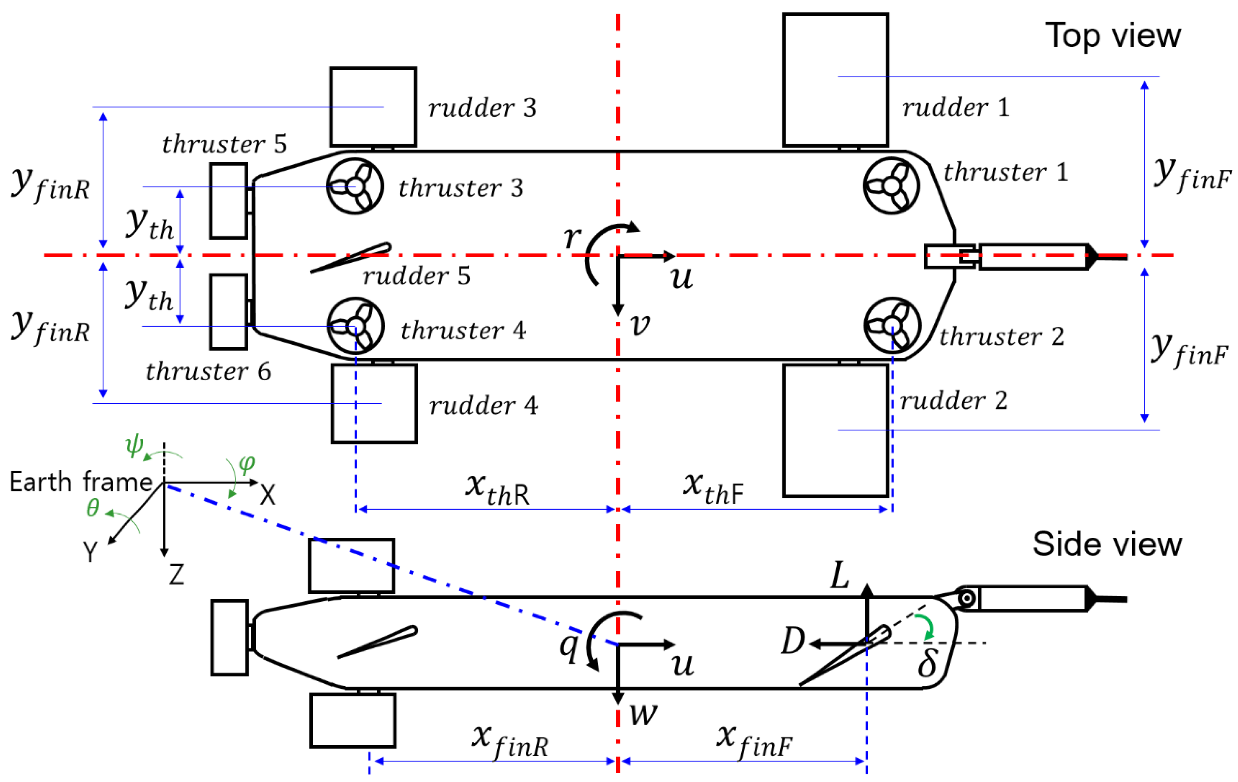
Figure 6 illustrates the arrangement of thrust and rudder in relation to the TUV’s 6DOF (six degrees of freedom) motion. The motion of a TUV in 6DOF can be described by the following vectors [
10,
11].
where
is the vector of position and attitude of a TUV.
x,
y,
z represent the Cartesian coordinates that indicate the position of the TUV in a 3D space. Additionally,
ϕ,
θ,
ψ represent the Euler angles that describe the attitude of the TUV.
is linear and angular velocities.
u, v and w represent the linear velocities along the body-fixed axes (x, y, z). p, q, and r represent the angular velocities along the body-fixed axes.
A general description of the six-degrees-of-freedom (6-DOF) equation of a TUV motion is presented as follows [
12,
13,
14,
15].
where M is the inertial matrix,
is the Coriolis-centripetal matrix,
is damping matrix,
is the gravitational and buoyancy forces.
is the vector of external forces and moments.
and
can be compensated through feedforward. The feedforward term and the PID compensation force were combined to produce the output force F of the feedforward compensation-based PID controller. By inputting the output force into the rudder and thrust models, we proposed a control algorithm for deriving the input signals for the TUV’s rudder angle and thruster to maintain its desired depth and attitude in this paper.
Figure 7 illustrates the depth control and posture control algorithms applied with the derived model. In
Figure 7, z
d represents the desired depth, p
d represents the desired roll angle, and q
d represents the desired pitch angle. Based on the forces estimated from the experiments, we can derive a feedforward term to maintain the TUV’s depth and attitude. This term compensates for both hydrostatic and hydrodynamic forces. The hydrostatic force corresponds to the buoyancy force of the TUV, while the hydrodynamic force is obtained using Equation (10) presented in this paper. To compensate for any remaining errors, we used a PID algorithm to generate a compensation force. The feedforward term and the PID compensation force were combined to produce the output force F of the feedforward compensation-based PID controller. Equation (15) represents a PID controller that tracks the desired depth z
d by incorporating a feed-forward term and an anti-windup. The feed-forward term is derived by substituting Equation (6) to Equation (9) into Equation (10).
Equations (16) and (17) are PID controllers for tracking the desired roll angle (
pd) and desired pitch angle (
qd), respectively, while incorporating an anti-windup.
The force
Fz and torques
Tp,
Tq, obtained through a PID controller, are allocated to rudders and thrusts through control allocation, determining the forces that need to be exerted by them.
Fz represents the force that the TUV needs to generate in the Z-axis direction,
Tq represents the torque that the TUV needs to generate in the Y-axis direction, and
Tp represents the torque that the TUV needs to generate in the X-axis direction. The control allocation for thrusters can be expressed as Equation (18).
Additionally, the control allocation for rudders can be expressed as Equation (19).
The output force of thrusters and rudder is converted into thruster input value and rudder angle using Equations (4) and (5). By inputting the output force into the rudder and thrust models, we proposed a control algorithm for deriving the input signals for the TUV’s rudder angle and thruster to maintain its desired depth and attitude.
4. Experimental Verification
The proposed TUV platform and control algorithm were validated through experiments conducted in a circulating water channel under various flow rate conditions. The detailed specifications of the circulating water channel are provided in
Table 2.
The experimental sequence is as follows:
Fix the towing cable to the front structure of the circulating water channel using a cable grip.
Bind the safety rope to the TUV platform and the safety rope to the crane.
Use the crane to launch the underwater platform into the circulating water channel
When operating the TUV platform, properly lower the crane so that there is no interference with the safety rope.
In addition, two safety ropes are installed on the outside of the circulating water channel at the rear left and right points of the TUV platform.
Check power supply and communication to the TUV platform.
Depth and posture (roll, pitch) maintenance control start, depth control target water depth is set to 1 m.
Driving the circulating water channel to generate flow rates from 0 knots to over 5 knots.
Change the depth control target depth of the TUV platform to 1.3 m when the flow rate reaches a steady state.
After 100 s, change the depth control target depth of the TUV platform to 1 m.
Check the depth and posture maintenance error data of the TUV platform.
As shown in
Figure 8, the TUV platform successfully maintained its posture and depth control in both stationary and high current flow states. Specifically,
Figure 8a demonstrates that the platform maintained its attitude and depth in a state of flow velocity stop, while
Figure 8b shows that it maintained posture and depth control at a tidal current of 5.7 knots.
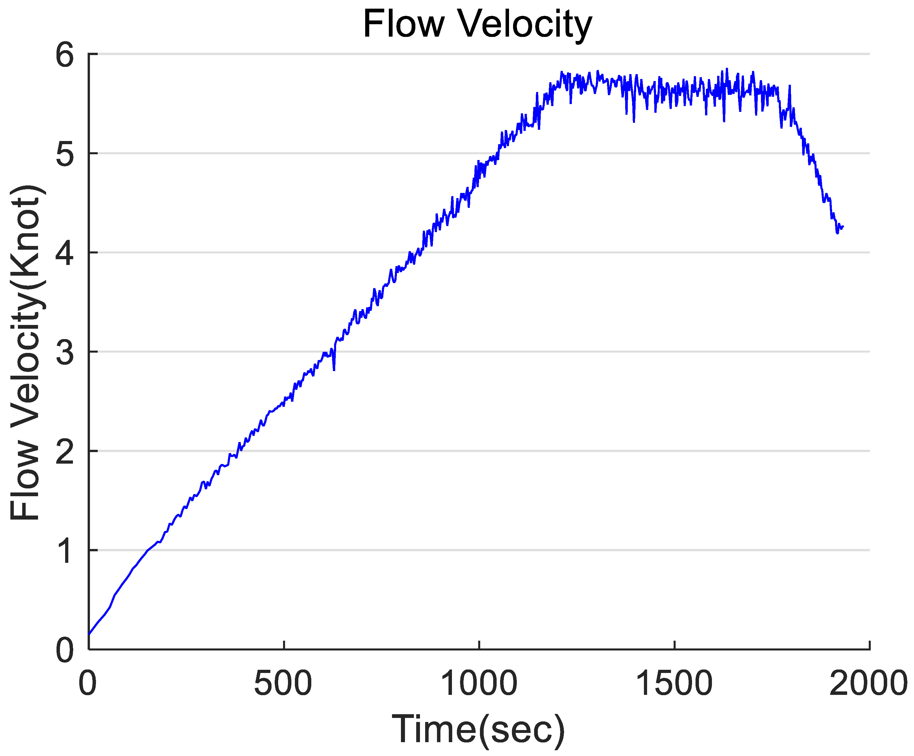
Figure 9 illustrates the measured flow velocities when the flow rate was varied from 0 knots to 5.7 knots in the circulating water channel.
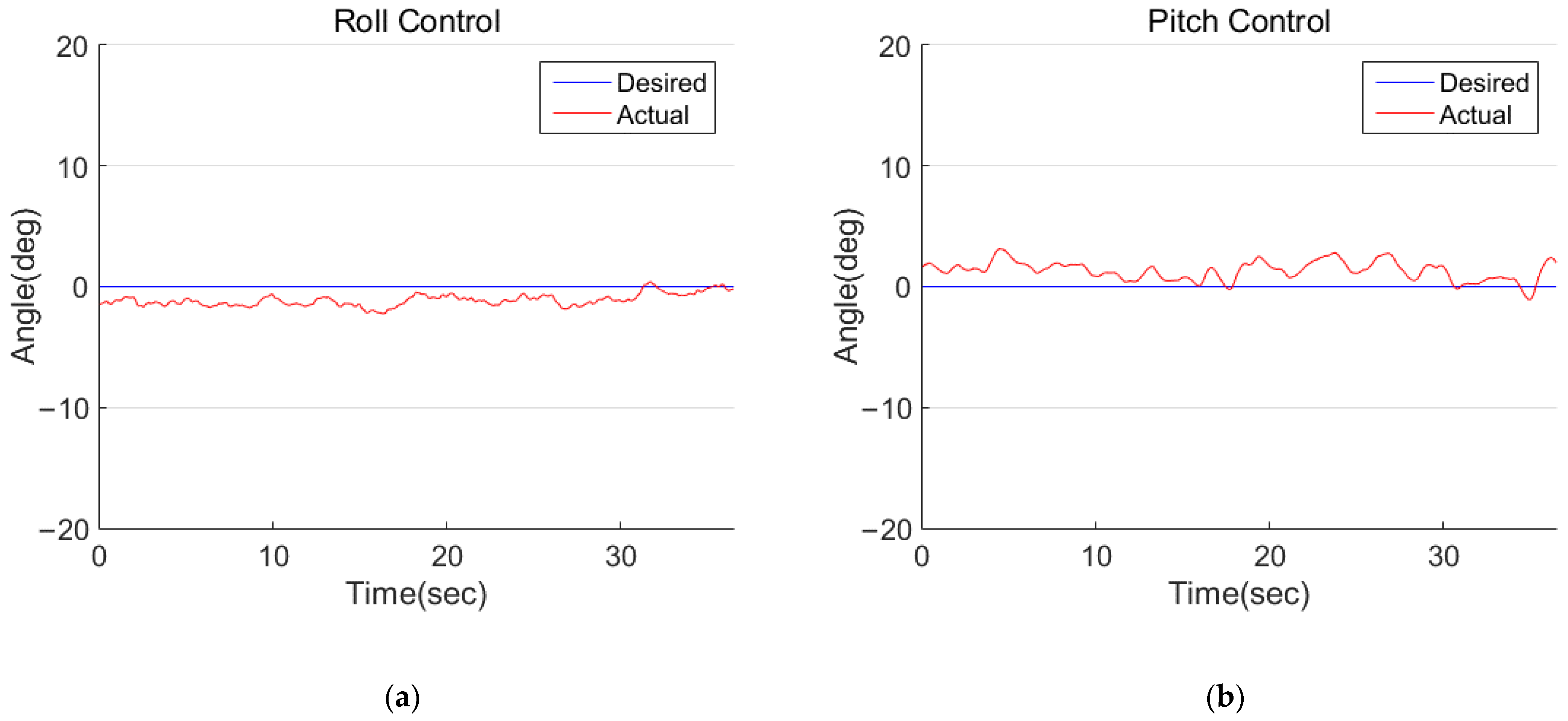
Figure 10 shows the results of the TUV maintaining depth through posture and depth control in a situation where flow velocities were varied from 0 knots to 5.7 knots in the circulating water channel. As the flow velocity changed, the tether cable exhibited significant vibrations, and a large number of air bubbles were generated, which significantly disturbed the TUV’s control performance. However, as shown in
Figure 10, the TUV successfully tracked the desired depth value. In the flow velocity of 5.7 knots, the TUV moved the depth from 1 m to 1.3 m. At a depth of 1.3 m, the measured roll angle and pitch angle values of the TUV are presented in
Figure 11a,b as graphs. The graph demonstrates that the TUV maintained its roll and pitch attitude in the flow velocity environment of 5.7 knots. In our previous research [
8], we presented the posture graph of the TUV in a circulating water channel with a flow velocity of 1 knot. Because we, in that study [
8], applied a PID controller with a simple feedforward gain without incorporating a model, the depth and attitude control performance was compromised at high flow velocities. As a result, we were unable to obtain experimental results regarding the control performance in high flow velocity environments.
However, in this study, we were able to assess the performance of posture and depth control in a flow velocity environment of 5.7 knots. Additionally, we confirmed that the TUV effectively controlled its depth and attitude in dynamically changing flow conditions. Thus, the experimental results validate the effectiveness of the proposed control algorithm for the new TUV platform.
5. Conclusions
In this study, we proposed a method for estimating a control model for a new TUV prototype capable of active movement, such as stationary or low-speed operation, and a depth and attitude control algorithm based on the estimated model. Additionally, we introduced a measuring device concept for lift force and drag force measurement caused by the underwater flow velocity. The experimental device was installed in a circulating water channel to estimate the TUV’s drag and lift forces.
Based on the estimated forces, we derived the feedforward term for maintaining the TUV’s depth and attitude, and used a PID algorithm to generate compensation forces for reducing error. The feedforward term and PID compensation forces were combined to produce the output force F of the feedforward compensation-based PID controller. By inputting the output force to the rudder and thrust models, we proposed a control algorithm for deriving the input signals for the TUV’s rudder angle and thruster to maintain its desired depth and attitude.
The proposed TUV platform and control algorithm were validated through experiments conducted in a circulating water channel under various flow rate conditions. The experimental results showed that the TUV could maintain depth and attitude control while transitioning from a stationary state to a high-current state of 5.7 knots. We plan to equip the TUV prototype with mission equipment and conduct operational experiments in real underwater environments in the future.
As a result of this research, we plan to conduct operational experiments in real sea environments by applying the proposed control algorithm to the TUV platform.

 ,
, 


