Article

Designing Protograph LDPC Codes for Differential Chaotic Bit-Interleaved Coded Modulation System for Underwater Acoustic Communications

1
Xiamen Key Laboratory of Marine Intelligent Terminal R&D and Application, School of Ocean Information Engineering, Jimei University, Xiamen 361021, China
2
Xiamen Key Laboratory of Mobile Multimedia Communications, School of Information Science and Engineering, Huaqiao University, Xiamen 361021, China
3
Faculty of Humanities and Social Sciences, University of Nottingham Ningbo China, Ningbo 315100, China
4
School of Information Engineering, Guangdong University of Technology, Guangzhou 510006, China
5
Navigation Institute, Jimei University, Xiamen 361021, China
*
Author to whom correspondence should be addressed.
J. Mar. Sci. Eng. 2023, 11(5), 914; https://doi.org/10.3390/jmse11050914
Submission received: 3 March 2023 / Revised: 19 April 2023 / Accepted: 22 April 2023 / Published: 24 April 2023
(This article belongs to the Special Issue Underwater Perception and Sensing with Robotic Sensors and Networks)

Abstract

:
Underwater acoustic (UWA) communications face many challenges, such as large multipath delay, severe fading and the time-varying distortions. Chaotic modulations have shown advantages in UWA communications, but the reliability of current chaotic modulations is still not guaranteed. In this paper, a short-length protograph low-density parity-check (P-LDPC) code design framework for the differential chaotic bit-interleaved coded modulation (DC-BICM) system for UWA communication is proposed. This design framework, considering the requirements of short codes in UWA communications, integrates the DC-BICM system, UWA channel and the differential evolutionary code searching algorithm. Through this design framework, the optimized short P-LDPC code can be obtained. Simulation results show that the DC-BICM system with the proposed P-LDPC code can obtain more than 0.48 dB coding gain and reduce 32.6%~69.5% of the average number of iterations compared with the counterparts. Moreover, the reconstructed underwater image with the proposed P-LDPC code is clearest with the highest peak-signal-noise ratio value when compared with counterparts.

1. Introduction

Underwater acoustic sensor networks (UASN), as important components of the underwater Internet of Things (UIoT), can strongly support the research for ocean science [1]. In the UASN, underwater acoustic (UWA) communication technology plays an important role in ocean information transmission. However, the current UWA communication technologies suffer from problems such as low throughput, low reliability, and high power consumption [2]. These problems are mainly caused by complicated UWA communication channels, including large multi-path delay, fading and different kinds of time-varying distortions.
Chaotic modulations adopt chaotic waveforms to bear information symbols [3]. Benefiting from anti-fading and anti-interference abilities, chaotic modulations have been considered as a good alternative technology for complex communication applications, including IoT scenarios, wireless body area networks (WBAN) and so on. Chaotic modulation can be clarified into two kinds: coherent and non-coherent. In coherent chaotic communication, chaotic shift keying (CSK) performs well in the price of complexity [4], which is an important factor to be considered in UWA communications. Non-coherent chaotic communications adopt the received signal and its delay version to perform correlation operations in the non-coherent demodulation process, and the complexity can be reduced effectively in this way [5]. In [6], a robust differential chaos shift keying (DCSK) was proposed, and it was further optimized as a frequency-modulated DCSK (FM-DCSK) [7], which was applied to the image transmission [8] considering only modulation without any other improved image processing method [9]. DCSK has advantages of low cost and low complexity due to the structure of the transmitted reference mode, and this structure does need channel estimation. Moreover, DCSK is robust to the multi-path fading and time-varied fading environment, which is suitable for the UWA communication environment [10].
Chaotic modulations have shown great potential and progress for UWA communications over the last two decades. A chaotic direct-sequence spread-spectrum (CDSSS) system was designed for UWA communications [11] and were further tested at the bay [12]. Moreover, the CDSSS system was also applied for secure UWA communications [13]. In [14], a multi-carrier chaotic modulation scheme was proposed for UWA communications. To further improve the system performance and security, a DCSK system based on orthogonal frequency-division multiplexing (OFDM) technology, named the OFDM-DCSK system, was introduced in [15]. Considering the higher requirements of low complexity and low power in UIoT scenarios, a joint energy and correlation detection-assisted non-coherent OFDM-DCSK system was proposed in [16]. However, dedicated research studies regarding coding schemes for DCSK-based UWA systems are quite limited, and these coding schemes are essential for reliable transmission in UWA communications.
We next survey the coding schemes used in UWA communications, we provide an overview on the coding schemes adopted in the DCSK-based systems, and then, we describe the contributions of this work.

1.1. Existing Coding Schemes for UWA Communications

Currently, the coding schemes designed for the UWA communications are considerably limited. In [17], convolutional codes and Reed Solomon codes were tested for UWA communications. Moreover, the multiple-input–multiple-output systems and space–time coding techniques were combined for high-rate communication for high-rate UWA transmission in [18]. In addition, the nonbinary LDPC codes were designed for multicarrier UWA communications [19]. In [20], an adaptive modulation and coding system was constructed for underwater OFDM transmission. Targeting UWA channels, the protograph low-density parity-check (LDPC) codes [21] were firstly investigated in [22], and the finite-length extrinsic information transfer (EXIT) analyses were proposed in [23]. Most recently, the deep joint source-channel coding and modulation scheme was proposed for UWA communications in [24].

1.2. The Coding Schemes for the DCSK-Based Systems

During the past several decades, many coding schemes have been developed to ensure reliability of the DCSK-based systems. The trellis-coded differential chaotic modulation (TC-DCM) scheme was proposed for band-limited systems [25]. To improve the performance of the TC-DCM system, the turbo TC-DCM system [26] was proposed, where two trellis codes are parallel concatenated with the M-ary DCSK scheme. The TC-DCM system with serial concatenated trellis codes [27] was proposed to achieve a lower error floor, compared with the turbo TC-DCM system. Further, the differential chaotic bit-interleaved coded modulation (DC-BICM) was proposed for the DCSK system over multipath Rayleigh channels [28], and the protograph LDPC (P-LDPC) codes were adopted in this system. The nonbinary P-LDPC codes were applied in the coded DCSK modulation over Rayleigh fading channels in [29], and this coded DCSK system has a simpler structure, compared with the DC-BICM system. An iterative receiver based on P-LDPC codes was proposed for the DCSK system to obtain better performance in [30], and then, the P-LDPC codes were redesigned for the iterative receiver [31]. This iterative receiver is a single-receiver model, not a multi-receiver model [32]. For power line communications (PLC), the performance and capacity of the DC-BICM system were analyzed in [33], and the P-LDPC codes were redesigned for the PLC channel. The combination of DC-BICM and the iterative receiver was studied in [34]. In [35], the P-LDPC code was redesigned for the DC-BICM system with the shuffled scheduling decoding algorithm. Moreover, the joint source and channel coding systems based on the double P-LDPC codes were used in the DCSK systems in [36,37].
However, the aforementioned coding schemes were not designed for the DCSK-based UWA communications, and this paper fulfills this gap by designing short P-LDPC codes for UWA communications with the DC-BICM system.
This paper includes the following contributions:
(1) The DC-BICM system with P-LDPC codes is investigated over the UWA channels, showing the potential benefits of this system.
(2) A design framework of short P-LDPC codes is proposed for the DC-BICM system over the UWA channels. This framework is based on the differential evolution algorithm, and the DC-BICM system is embedded in the design process. Simulation results show that the designed P-LDPC codes achieve good performance for the DC-BICM-based UWA communications.
The remainder of the paper is organized as follows. Section 2 describes the DC-BICM system and the UWA channel model. The design framework of short P-LDPC codes is presented in Section 3. Simulation results are provided in Section 4, and this paper is finally concluded in Section 5.

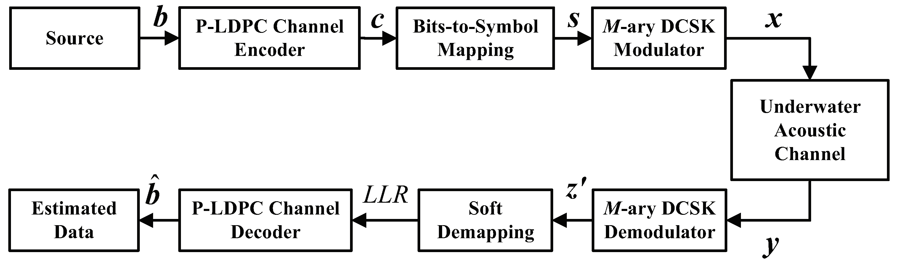
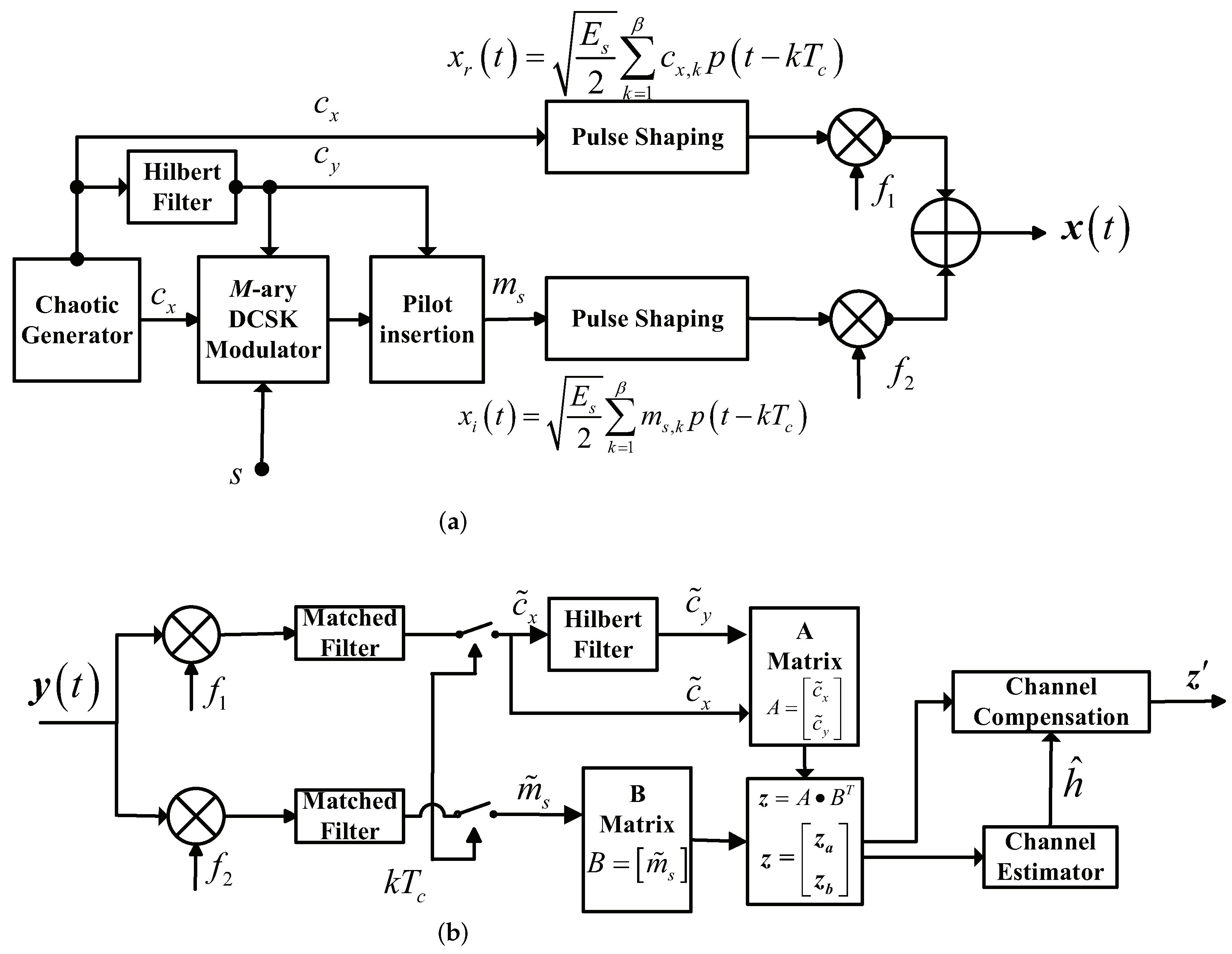
2. The DC-BICM System over Underwater Acoustic Channels

In this section, the DC-BICM system is described in detail, and the UWA channel adopted in this paper is also elaborated.
The system model is shown in Figure 1. At the transmitter, a binary independent and identically distributed (i.i.d.) source generates the information sequence b = { b 1 , b 2 , , b k } . Then, it is encoded by the P-LDPC channel encoder to the codeword sequence c = { c 1 , c 2 , , c n } . Using the generalized variable degree matched mapping (GVDMM) rule [38], the codeword sequence c is mapped to the transmitted symbol sequence s = { s 1 , s 2 , , s l } , s S , S = { 0 , 1 , , M 1 } , M = 2 t and t N + , l = n / M , where S is the set of signal labels. Here, the square constellation is adopted. Further, the symbol sequence s is modulated by the M-ary DCSK modulator to obtain the transmitted signal x . In this process, a chaotic reference signal c x = { c x , 1 , c x , 2 , , c x , β } is generated by the chaotic generator with logistic mapping, i.e., x k + 1 = 1 2 x k 2 . The length of this chaotic reference signal is β , defined as the spreading factor. Another length- β signal c y = { c y , 1 , c y , 2 , , c y , β } is the quadrature version of c x , and it is obtained from c x by the Hilbert transform. These two independent orthogonal chaotic signals c x and c y are used to constitute the information-bearing signal m s , given by m s = a s c x + b s c y , where a s and b s represent the real part and imaginary part of the a complex symbol s i , 1 i l , respectively. Finally, the transmitted signal x is made up of c x and m s , as described in the following.
Figure 2a depicts the structure of the M-ary DCSK modulator. The transmitted signal for the i-th symbol duration is
x ( t ) = x r ( t ) cos 2 π f 1 t + ϕ 1 + x i ( t ) cos 2 π f 2 t + ϕ 2 ,
where x r ( t ) and x i ( t ) represent the reference signal and the information-baring signal, respectively. Moreover, ϕ 1 and ϕ 2 represent the phase angles of the orthogonal modulated carriers, respectively, and f 1 and f 2 denote the frequencies of these two carries, respectively. The expressions of x r ( t ) and x i ( t ) are given by
x r ( t ) = E s 2 k = 1 β c x , k p t k T c , x i ( t ) = E s 2 k = 1 β m x , k p t k T c ,
where E s is the symbol energy, T c is the chip time, and p ( t ) is the square-root-raised-cosine filter. The transmitted signal x is then sent over the UWA channel [39,40], modeled as
h ( t ) = = 0 L 1 h ( t ) δ t T c ,
where the channel memory length L is set to 24, the Rayleigh fading taps are assumed with an exponentially decaying power delay profile losing 1.66 dB per tap, and δ ( · ) is the Dirac delta function. The information symbol duration is defined as T s = 2 β T c . The taps h ( n ) have the following correlation structure:
E h t h ( t ) * = J 0 2 π t t f D T c δ ,
where J 0 ( · ) is the first-kind Bessel function with zero orders, h ( t ) * is the conjugate of the h ( t ) , and f D is the maximum Doppler frequency.
The structure of the M-ary DCSK demodulator is shown in Figure 2b. The received signal is given by
y ( t ) = h ( t ) x ( t ) + n ( t ) ,
where n ( t ) represents the additive white Gaussian noise (AWGN), and ⊗ means convolution operation. When y ( t ) is received by the M-ary DCSK demodulator, two corresponding modulated carrier frequencies are used to separate y ( t ) . Next, two corresponding matched filters are adopted for these separated signals, and then, the filtered signals are sampled. In this way, the chaotic reference signal and information signal are demodulated, denoted by c x ˜ and m s ˜ , respectively. Using the Hilbert filter, the signal c y ˜ is obtained from c x ˜ . In this way, the decision variable z = ( z a , z b ) can be obtained by [28]
z a l = 1 L h l 2 a s E S / 2 + k = 1 β l = 1 L h l E S / 2 c x , k τ l η k + β + k = 1 β l = 1 L h l E S / 2 a S c x , k τ l + b s c y , k τ l η k + k = 1 β η k η β + k ,
z b l = 1 L h l 2 b s E S / 2 + k = 1 β l = 1 L h l E S / 2 c x , k τ l η k + β + k = 1 β l = 1 L h l E S / 2 a s c x , k τ l + b S c y , k τ l η k ˜ + k = 1 β η k ˜ η β + k .
Normalized signal z can be computed by z = z / h · E s 2 , where h = l = 1 L α l 2 denotes the partial channel state information. The conditional probability density function (PDF) of z = ( z a , z b ) for the m-th modulated symbol is given by
p z s m = 1 2 π σ ¯ 2 exp z a μ a ¯ 2 + z b μ b ¯ 2 2 σ ¯ 2 ,
where the means of z a and z b are denoted by μ a ¯ and μ b ¯ , respectively. Additionally, σ ¯ 2 represents the variance of z a and z b , as they have the same variance. Then, z is used to calculate the log-likelihood ratios (LLRs) L z by the soft demapper using the Gaussian approximation (GA) method, i.e.,
L z ( i ) = log m : d i ( m ) = 0 p z s m p s m m ¯ : d i ( m ¯ ) = 1 p z s m ¯ p s m ¯ ,
where p ( s m ) represents a priori probability of the m-th symbol s m . Finally, the LLRs are adopted as the initial information by the P-LDPC decoder with the belief propagation (BP) decoding algorithm, and the outputs of the decoder are the estimated source sequence b ^ .
The belief propagation (BP) decoding algorithm is described briefly [35]. The BP decoding algorithm includes four steps:
Step 1. 
Initialization. The LLRs L z ( i ) obtained from the soft demapping module in the DC-BICM system (Equation (9)) feeds into the P-LDPC channel decoder to initialize the LLR messages in the decoder.
Step 2. 
LLRs updating. This step consists of two kinds of message-updating processes. The first is the check-to-variable (CTV) message updating from the check node (CN) to the variable node (VN) in the P-LDPC codes, and the second is the variable-to-check (VTC) message updating from the VN to the CN in the P-LDPC codes. The two procedures run in turn.
Step 3. 
Termination decision. When the maximum iteration number is reached or the decoded sequence satisfies the parity-check equation, the iteration of Step 2 will terminate. Otherwise, the iteration between the CTV message updating and VTC message updating in Step 2 will continue.
Step 4. 
Output. When the iteration stops, the decoded sequence will output as the estimated source sequence.
Note that the LLRs L z ( i ) calculated by the demapping module from the demodulator of the DC-BICM system have important effects on the P-LDPC decoder. They are closely related.

3. Proposed Design of Protograph LDPC Codes for the DC-BICM-System-Based UWA Communications

In UWA communications, the packet length is usually short [20]. In this case, the existing theoretical analysis tool, such as the EXIT algorithm [41] or protograph EXIT (PEXIT) algorithm [42], would not be accurate. Inspired by the work [43,44], we propose a design framewok of short P-LDPC codes for the DC-BICM system over UWA channels, and the proposed design framework is detailed in Algorithm 1.
This algorithm mainly consists of two parts, namely Initialization and the Code design process.
Initialization. This part determines the structure of the initial base matrix B i n i t and the parameters of the code searching algorithm. Generally, in the design process of the P-LDPC codes, decoding threshold, linear minimum distance growth (LMDG) and code searching complexity have to be considered. A good base matrix usually contains one or more degree-1 variable nodes (VNs), some degree-2 VNs and a punctured high-degree VN. Meanwhile, the maximum number of degree-2 VNs N d 2 m a x is directly related to the LMDG property directly, and the relation is specified by
N d 2 N d 2 m a x = m N d 1 1 ,
where N d 1 and N d 2 are the numbers of degree-1 and degree-2 VNs, respectively. Moreover, the size of the base matrix is of great importance on the searching complexity and optimization space, i.e., the tradeoff between the base matrix dimension and the design complexity needs to be considered. Taking all these factors into consideration, the initialization parameters are given in Table 1. A rate-1/2 protograph base matrix with size 6 × 10 is considered, where the number of the degree-1 VN and degree-2 VN is 2. In the code design process, 50 candidates and 2000 generations are adopted.
Algorithm 1: The Proposed Design Framework of P-LDPC Codes for the DC-BICM System over UWA Channels
Initialization:
  • (a) Determine the parameters of base matrix B i n i t , including code rate, size, puncture position and so on.
  • (b) Calculate the key parameters of the base matrix, including the number of degree-1 and degree-2 VNs ( N d 1 and N d 2 ).
  • (c) Choose the appropriate parameters of the code searching algorithm, including the number P of candidates, crossover probability p c , mutation probability p m and so on.
  • (d) Choose the design signal-to-noise ratio according to the scenario requirement.
Code Design Process:
1:
Generate P base matrices B ( 1 ) [ p ] randomly with initialized parameters in Table 1, p = { 1 , 2 , , P } .
2:
for  g = 1 ; g G ; g + + do
3:
   for p = 1 ; p P ; p + +  do
4:
       Use PEG algorithm to generate the corresponding PCMs H ( g ) [ p ] .
5:
       Apply H ( g ) [ p ] to the DC-BICM system over UWA channels, evaluate the BER at a certain SNR value, and save the BER result to V B E R ( g ) [ p ] .
6:
   end for
7:
   Perform the crossover and mutation operations to update the base matrices and obtain B ( g + 1 ) [ p ] :
8:
   for  p = 1 ; p < P ; p + + do
9:
       Mutation operation:
M ( g ) [ p ] = round ( B ( g ) [ r 1 ] + p m ( B ( g ) [ r 2 ] B ( g ) [ r 3 ] ) ) ,
       where r 1 , r 2 , r 3 are chosen from { 1 , 2 , , P } randomly.
10:
     Crossover operation:
D ( g ) [ p ] = M ( g ) [ p ] with probability p c , B ( g ) [ p ] with probability 1 p c .
11:
       if  V B E R ( g ) [ p ] < V B E R ( g 1 ) [ p ]  then
12:
            B ( g + 1 ) [ p ] = B ( g ) [ p ] ,
13:
       else
14:
            B ( g + 1 ) [ p ] = D ( g ) .
15:
       end if
16:
   end for
17:
end for
18:
ρ = arg min p V B E R ( G ) [ p ] , p = { 1 , 2 , , P }
19:
return  B ( G ) [ ρ ]
The base matrix is initialized as
B i n i t = 0 1 1 0 0 0 0 0 0 0 0 0 | b 1 , 3 b 1 , 4 b 1 , 5 b 1 , 6 b 1 , 7 b 1 , 8 b 1 , 9 b 1 , 10 b 2 , 3 b 2 , 4 b 2 , 5 b 2 , 6 b 2 , 7 b 2 , 8 b 2 , 9 b 2 , 10 b 3 , 3 b 3 , 4 b 3 , 5 b 3 , 6 b 3 , 7 b 3 , 8 b 3 , 9 b 3 , 10 b 4 , 3 b 4 , 4 b 4 , 5 b 4 , 6 b 4 , 7 b 4 , 8 b 4 , 9 b 4 , 10 b 5 , 3 b 5 , 4 b 5 , 5 b 5 , 6 b 5 , 7 b 5 , 8 b 5 , 9 b 5 , 10 b 6 , 3 b 6 , 4 b 6 , 5 b 6 , 6 b 6 , 7 b 6 , 8 b 6 , 9 b 6 , 10 ,
where b i , j = { 0 , 1 } , i = { 1 , 2 , , 6 } , and j = { 3 , 4 , , 10 } .
Code design process. This part realizes the code-searching process based on the differential evolution (DE) algorithm [45]. First, generate P base matrices B ( 1 ) [ p ] randomly from B init with the parameters in Table 1 (Line 1). At the g-th generation, p parity-check matrices (PCMs) H ( g ) [ p ] are constructed from B ( g ) [ p ] by the progressive edge growth (PEG) algorithm [46]. Note that the length-4 cycles are avoided as much as possible in the PEG process. Then, these PCMs are applied in the DC-BICM system over UWA channels to evaluate the bit error rate (BER) at a certain signal-to-noise ratio, and the results are saved to V B E R ( g ) [ p ] . Note that V B E R ( 0 ) [ p ] , p = { 1 , 2 , , P } are all set to 1. When all BERs are obtained, the crossover and mutation operations are used to generate new base matrices according to Equation (12) and Equation (11). Afterward, the base matrices are updated according to the BER values (Lines 11–15). After G generations, the base matrix with the lowest BER is chosen as the optimized result.
Using the proposed design framework, the optimized base matrix is given by
B o p t U W A = 0 1 0 0 1 1 0 0 0 1 1 0 0 0 1 1 1 0 0 0 0 0 1 1 1 1 1 1 0 0 0 0 0 0 1 1 1 1 1 1 0 0 0 1 1 0 0 1 1 1 0 0 1 0 0 1 0 0 1 1 .

4. Simulation Results and Discussions

This section presents the simulation results, which consist of two parts: performance comparison between the optimized P-LDPC code and the existing codes and underwater image transmission comparison. The simulation environment is in C++ language using Visual Studio 2019 with an Intel(R) Core(TM) i7-10700F CPU (2.90 GHz). The code length is fixed at 500 bits for all simulations. The maximum frame number is 1 × 10 6 , and the simulation is terminated when there are 100 frame errors at each SNR value. We denote the optimized codes from ([35], Equation (12)), ([31], Equation (12)), ([34], Equation (20)), ([35], Equation (8)) and ([33], Equation (29)) by B AR 4 JA , B A 1 , B A 2 , B A 3 , and B A 4 , respectively. The maximum number of iterations in the decoding process is 50. The normalized Doppler frequency f D T s is set to 10 5 [40]. The other parameters of the utilized UWA channel are described in Section 2.

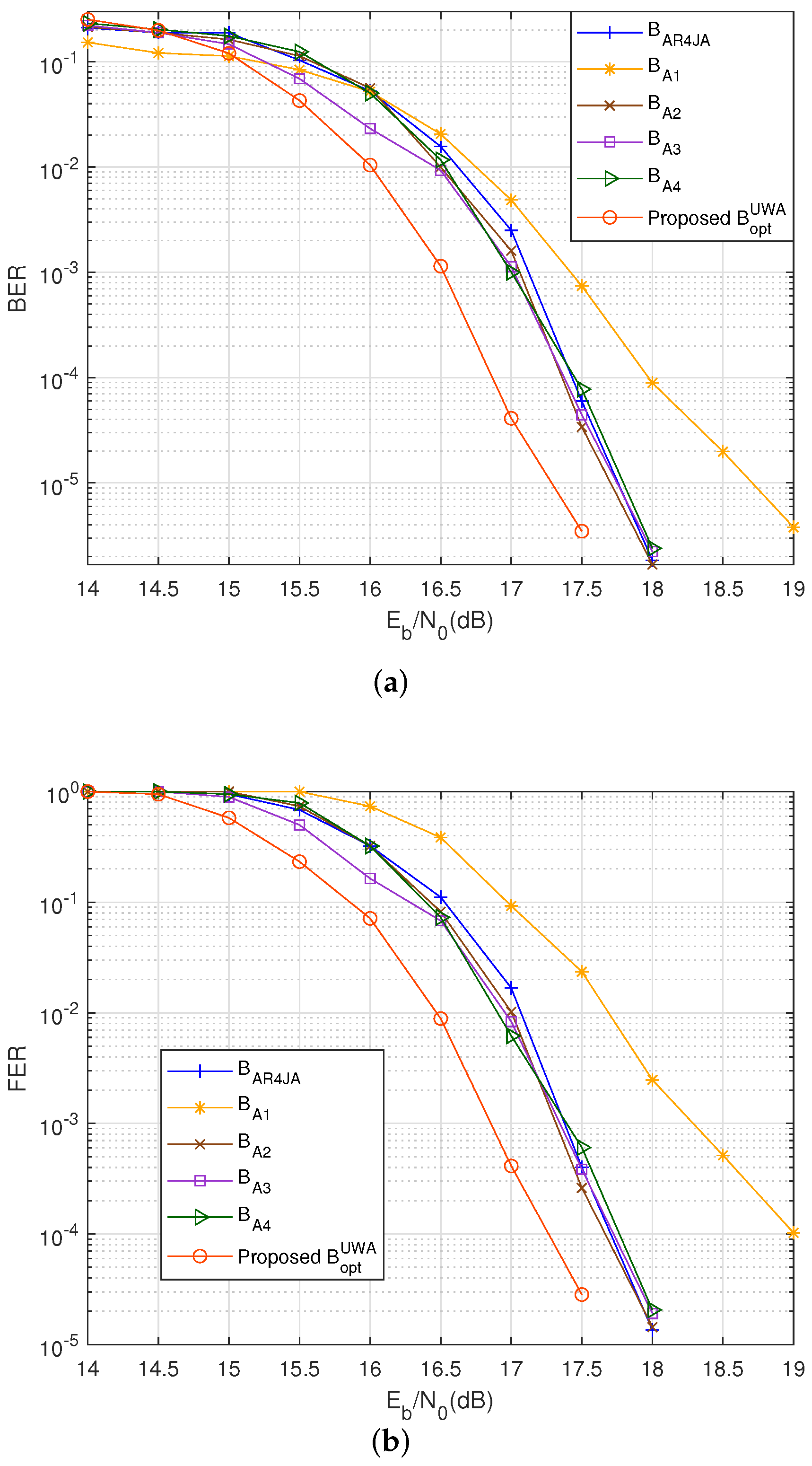
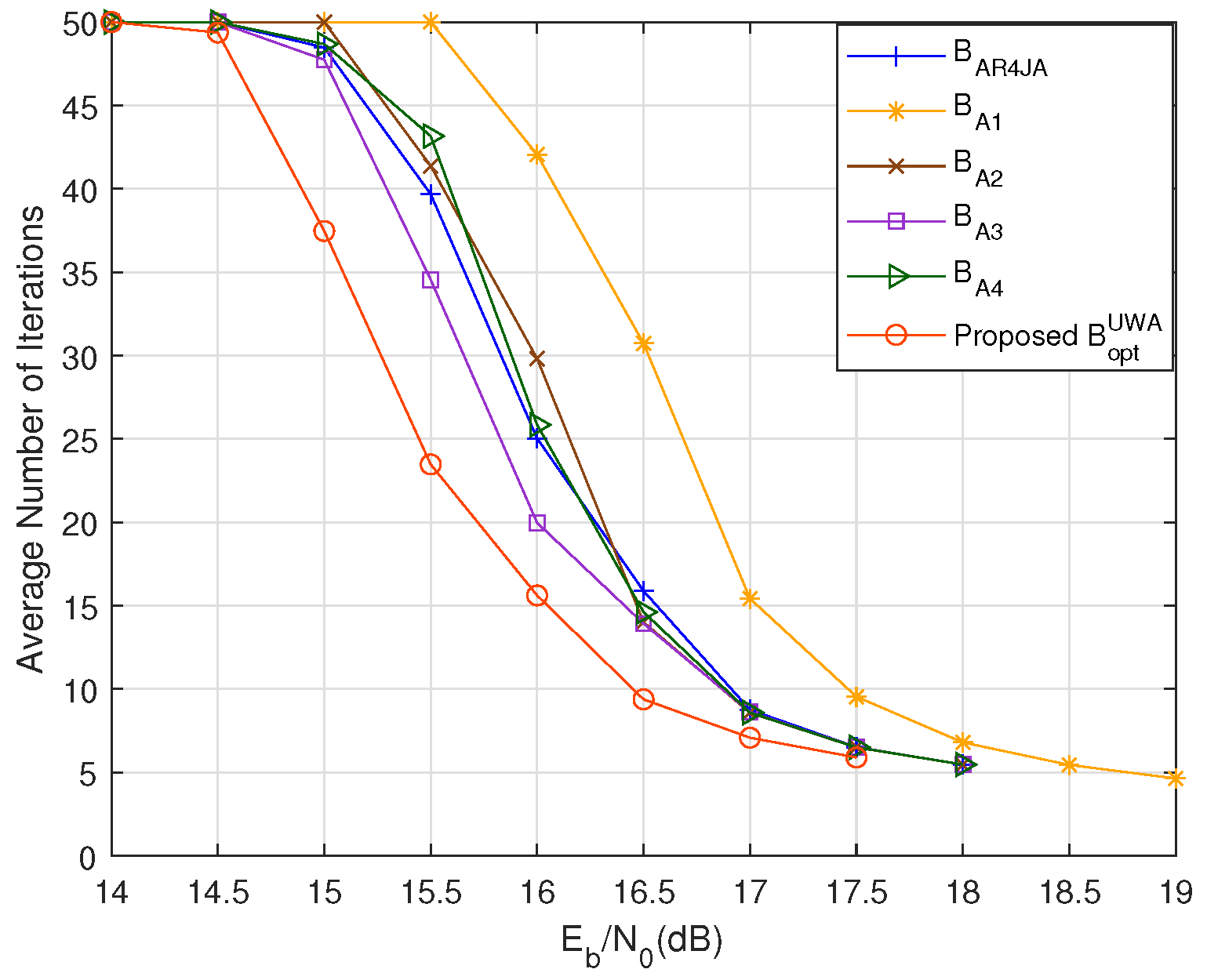
4.1. Performance Comparison

Figure 3 compares the BER and frame error rate (FER) performance, respectively, between the proposed B o p t U W A and other P-LDPC codes for the DC-BICM system over the UWA channels. In Figure 3a, B o p t U W A achieves coding gains of 0.6, 0.9, 0.54, 0.49 and 0.48 dB at B E R = 1 × 10 3 , compared with B AR 4 JA , B A 1 , B A 2 , B A 3 , and B A 4 , respectively. Moreover, B o p t U W A outperforms B A 1 by 1.53 dB at B E R = 4 × 10 6 . In addition, the proposed B o p t U W A performs best among these codes for the DC-BICM system over the UWA channels. In other words, the existing P-LDPC codes are all not suitable for the DC-BICM system over the UWA channel, and the proposed design framework is essential and meaningful. It can be seen from Figure 3b that FER performance has the same trend as the BER curves.
Figure 4 compares the average number of iterations. As shown in this figure, B AR 4 JA , B A 2 , B A 3 , and B A 4 all converge faster than B A 1 , and B o p t U W A converges fastest among them. It is noted that at E b / N 0 = 16.5 dB, the number of iterations for B o p t U W A is reduced by around 40.9 % , 69.5 % , 33 % , 32.6 % , and 35.8 % , respectively, compared to B AR 4 JA , B A 1 , B A 2 , B A 3 , and B A 4 .
From Figure 3 and Figure 4, it can be seen that the DC-BICM system with proposed B o p t U W A can perform best in both error-rate performance and converge speed.

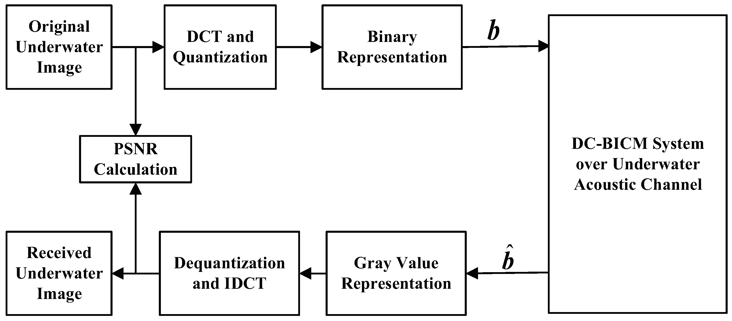
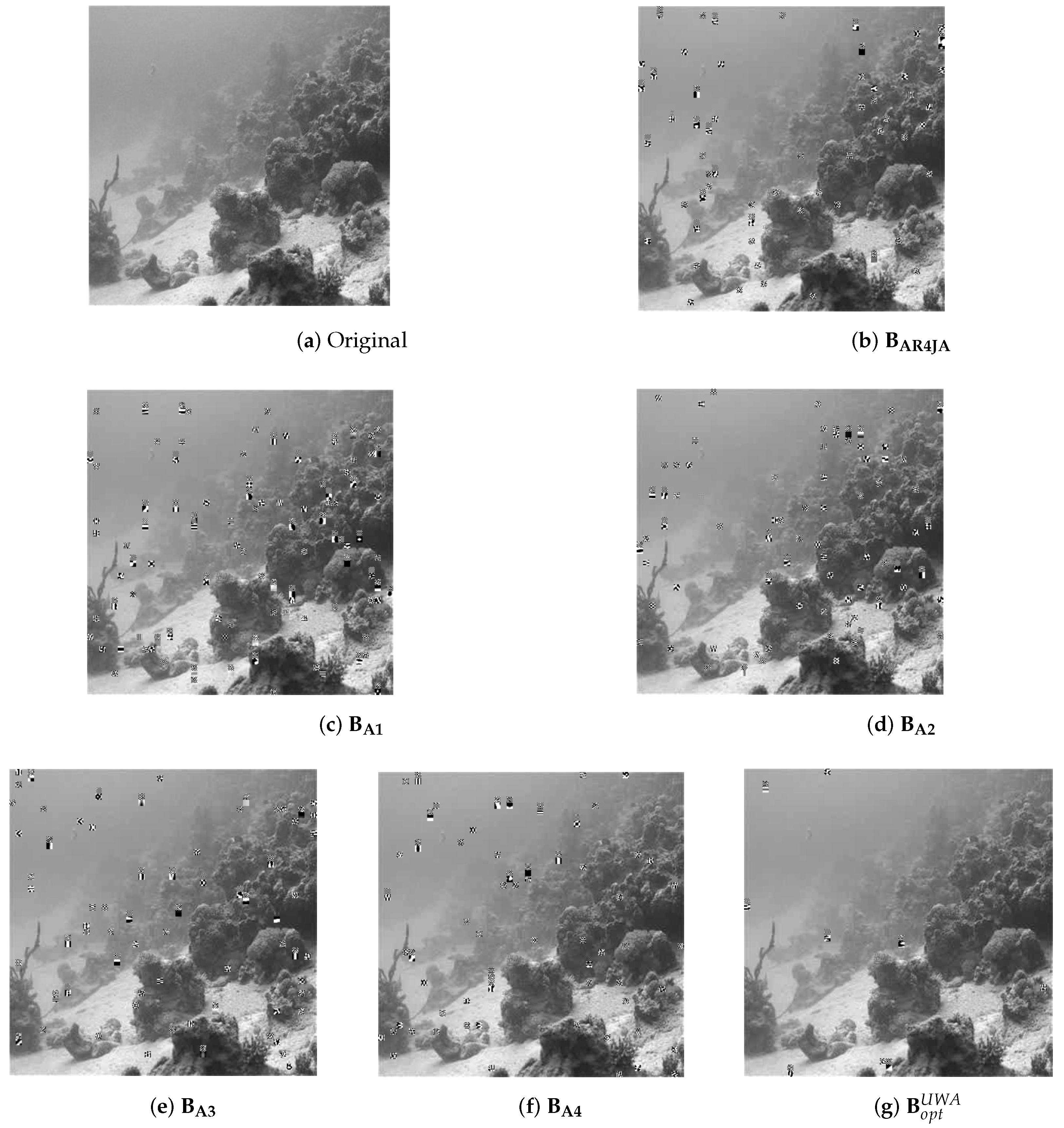
4.2. Underwater Image Transmission Comparisons

To test and verify the performance of the DC-BCIM system with the proposed B o p t U W A over the UWA channel, the underwater image transmission comparisons are presented in this part.
The underwater image transmission system is shown in Figure 5. The process of image pre-processing includes the discrete cosine transform (DCT) and quantization. Through the pre-processing operation, the underwater image can be represented by binary bit streams, and these bit streams are divided into frames with equal length. Then, these equal-length frames are fed into the P-LDPC channel encoder of the DC BICM system over the UWA channel (shown in Figure 1), and the P-LDPC channel decoder outputs the estimated sequence. This estimated sequence goes to the image post-processing operation to recover the underwater image and to calculate the image quality. The post-processing operation includes the calculation of the gray values of the received image and the inverse DCT (IDCT) operation. After the IDCT operation, the original underwater image is recovered. The processes of image pre-processing and post-processing are the same the process of [47]. The image transmission system in [47] is a combination of the joint source-channel coding and separated source-channel coding (SSCC) technologies, and the underwater image transmission system in this paper is a kind of SSCC system. Moreover, we compare the performance between the proposed P-LDPC code and its counterparts in this system. They are all single-receiver [28] and not multi-receiver architectures [48], and that which we focus on in this paper is code design.
The peak signal-to-noise ratio (PSNR) is adopted to describe the quality of recovered images objectively, and the recovered images are also shown to describe the quality directly. The PSNR is computed by
P S N R = 10 × lg A 2 × W × L m = 1 W n = 1 L I T ( m , n ) I R ( m , n ) 2 ,
where W × L is the size of the underwater image size, and the original image and recovered image are represented by I T ( m , n ) and I R ( m , n ) , respectively. The peak value of signals for the gray underwater images is represented by A, whose value is 255.
Figure 6 shows the reconstructed underwater images with different codes when E b / N 0 = 17 dB. It can be seen that the reconstructed image with B AR 4 JA is clearer than the images with B A 1 , B A 2 , B A 3 and B Ar , and the quality of the reconstructed images with B A 1 (Figure 6c) is the worst among these images. The reconstructed images with B o p t U W A are clearest (Figure 6g).
Table 2 shows the PSNR value comparisons with different codes when E b / N 0 = 17 dB. From this table, we can see that the reconstructed image with B AR 4 JA has a higher PSNR value than B A 1 , B A 2 , B A 3 and B Ar . The PSNR value of the reconstructed image with B o p t U W A is highest, and the reconstructed image with B A 1 is the worst. This is consistent with the quality of the reconstructed images mentioned above.
From Figure 6 and Table 2, we can see that the DC-BICM system with proposed B o p t U W A can perform better than their counterparts in the underwater image transmission, which further shows the efficiency and advantage of the proposed design framework.

5. Conclusions

In this paper, we investigate the performance of a P-LDPC coded DC-BICM system over UWA channels, which greatly improves the transmission reliability. Moreover, we propose a short-length P-LDPC code design framework for the DC-BICM system, integrating the DC-BICM system, UWA channel and the DE code searching algorithm. With this design framework, an optimized short-length P-LDPC code is obtained. Simulation results show that the proposed P-LDPC code outperforms their counterparts in terms of error correction performance and convergence speed, and underwater image transmission comparisons show that images with the proposed P-LDPC code can achieve the highest PSNR value and have the best image quality. This means that the proposed design framework for the DC-BICM system for the UWA channel is meaningful and effective. This paper fills the vacancy in the research regarding designing short P-LDPC codes for UWA communications with the DC-BICM system, which contributes to improve the reliability of a coded chaotic modulation for UWA communication. In the future, the low complexity receiver will be further investigated for the DC-BICM system and UWA channel.

Author Contributions

Conceptualization, Z.X., Q.C., G.C. and J.Z.; Data curation, Z.X., G.C. and L.L; Formal analysis, Z.X., G.C. and L.L.; Funding acquisition, Z.X., Q.C. and J.Z.; Investigation, Z.X. and G.C.; Software, Z.X. and G.C.; Writing—original draft, Z.X.; Writing—review and editing, Z.X, Y.L., G.C. and Y.S. All authors have read and agreed to the published version of the manuscript.

Funding

This work was supported by the Fujian Province Young and Middle-aged Teacher Education Research Project (No. JAT220182), Jimei University Startup Research Project (No. ZQ2022015), the Scientific Research Foundation of Jimei University (No. XJ2022000201), the Xiamen Ocean and Fishery Development Special Fund Project (No. 21CZB013HJ15), the Xiamen Key Laboratory of Marine Intelligent Terminal R&D and Application (No. B18208), the Fund Project of Jimei University (No. ZP2020042), the National Natural Science Foundation of China (No. 62101195) and the Natural Science Foundation of Fujian Province of China (No. 2020J05056).

Institutional Review Board Statement

Not applicable.

Informed Consent Statement

Not applicable.

Data Availability Statement

The original contributions presented in the study are included in the article. Further inquiries can be directed to the corresponding author.

Conflicts of Interest

The authors declare no conflict of interest.

Abbreviations

The following abbreviations are used in this manuscript:
UWAUnderwater Acoustic
DC-BICMDifferential Chaotic Bit-interleaved Coded Modulation
UASsUnderwater Acoustic Sensor networks
IoTInternet of Things
UIoTUnderwater Internet of Things
CDSSSChaotic Direct-Sequence Spread Spectrum
DCSKDifferential Chaos Shift Keying
OFDMOrthogonal Frequency-division Multiplexing
LDPCLow-Density Parity Check
P-LDPCProtograph Low-Density Parity Check
EXITExtrinsic Information Transfer
TC-DCMTrellis-Coded Differential Chaotic Modulation
GVDMMGeneralized Variable Degree Matched Mapping
AWGNAdditive White Gaussian Noise
LLRLog-Likelihood Ratios
GAGaussian Approximation
BPBelief Propagation
LMDGLinear Minimum Distance Growth
VNVariable Nodes
PCMParity-Check Matrices
PEGProgressive Edge Growth
BERBit Error Rate
FERFrame Error Rate

References

  1. Liu, Y.; Wang, H.; Cai, L.; Shen, X.; Zhao, R. Fundamentals and advancements of topology discovery in underwater acoustic sensor networks: A review. IEEE Sens. J. 2021, 21, 21159–21174. [Google Scholar] [CrossRef]
  2. Zhang, R.; Ma, X.; Wang, D.; Yuan, F.; Cheng, E. Adaptive coding and bit-power loading algorithms for underwater acoustic transmissions. IEEE Trans. Wirel. Commun. 2021, 20, 5798–5811. [Google Scholar] [CrossRef]
  3. Hayes, S.; Grebogi, C.; Ott, E. Communicating with chaos. Phys. Rev. Lett. 1993, 70, 3031. [Google Scholar] [CrossRef] [PubMed]
  4. Dedieu, H.; Kennedy, M.P.; Hasler, M. Chaos shift keying: Modulation and demodulation of a chaotic carrier using self-synchronizing Chua’s circuits. IEEE Trans. Circuits Syst. II Analog. Digit. Signal Process. 1993, 40, 634–642. [Google Scholar] [CrossRef]
  5. Cai, X.; Xu, W.; Wang, L.; Chen, G. Towards high-data-rate noncoherent chaotic communication: A multiple-mode differential chaos shift keying system. IEEE Trans. Wirel. Commun. 2021, 20, 4888–4901. [Google Scholar] [CrossRef]
  6. Kolumbán, G.; Vizvári, B.; Schwarz, W.; Abel, A. Differential chaos shift keying: A robust coding for chaos communication. In Proceedings of the NDES, Seville, Spain, 27–28 June 1996; Volume 96, pp. 87–92. [Google Scholar]
  7. Kolumbán, G.; Kis, G.; Kennedy, M.; Jáko, Z. FM-DCSK: A new and robust solution to chaos communications. In Proceedings of the International Symposium on Nonlinear Theory and Its Applications, Honolulu, HI, USA, 29 November–3 December 1997; pp. 117–120. [Google Scholar]
  8. Ding, Q.; Wang, J. Design of frequency-modulated correlation delay shift keying chaotic communication system. IET Commun. 2011, 5, 901–905. [Google Scholar] [CrossRef]
  9. Zhang, X.; Yang, P.; Feng, X.; Sun, H. Efficient imaging method for multireceiver SAS. IET Radar Sonar Navig. 2022, 16, 1470–1483. [Google Scholar] [CrossRef]
  10. Escribano, F.J.; Kaddoum, G.; Wagemakers, A.; Giard, P. Design of a new differential chaos-shift-keying system for continuous mobility. IEEE Trans. Commun. 2016, 64, 2066–2078. [Google Scholar] [CrossRef]
  11. Azou, S.; Burel, G.; Pistre, C. A chaotic direct-sequence spread-spectrum system for underwater communication. In Proceedings of the OCEANS’02 MTS/IEEE, Biloxi, MI, USA, 29–31 October 2002; Volume 4, pp. 2409–2415. [Google Scholar]
  12. Azou, S.; Burel, G.; Le Duff, L.; Pistre, C. Sea trial results of a chaotic direct-sequence spread spectrum underwater communication system. In Proceedings of the Oceans 2003. Celebrating the Past… Teaming Toward the Future (IEEE Cat. No. 03CH37492), San Diego, CA, USA, 22–26 September 2003; Volume 3, pp. 1539–1546. [Google Scholar]
  13. Shu, X.; Wang, J.; Wang, H.; Yang, X. Chaotic direct sequence spread spectrum for secure underwater acoustic communication. Appl. Acoust. 2016, 104, 57–66. [Google Scholar] [CrossRef]
  14. Chen, M.; Xu, W.; Wang, D.; Wang, L. Multi-carrier chaotic communication scheme for underwater acoustic communications. IET Commun. 2019, 13, 2097–2105. [Google Scholar] [CrossRef]
  15. Cai, X.; Hu, L.; Xu, W.; Wang, L. Design of an OFDM-based differential cyclic-shifted DCSK system for underwater acoustic communications. In Proceedings of the 2021 26th IEEE Asia-Pacific Conference on Communications (APCC), Kuala Lumpur, Malaysia, 11–13 October 2021; pp. 304–309. [Google Scholar]
  16. Cai, X.; Xu, W.; Wang, L.; Kaddoum, G. Joint energy and correlation detection assisted non-coherent OFDM-DCSK system for underwater acoustic communications. IEEE Trans. Commun. 2022, 70, 3742–3759. [Google Scholar] [CrossRef]
  17. Goalic, A.; Trubuil, J.; Beuzelin, N. Channel coding for underwater acoustic communication system. In Proceedings of the OCEANS 2006, Boston, MA, USA, 18–21 September 2006; pp. 1–4. [Google Scholar]
  18. Roy, S.; Duman, T.M.; McDonald, V.; Proakis, J.G. High-rate communication for underwater acoustic channels using multiple transmitters and space–time coding: Receiver structures and experimental results. IEEE J. Ocean. Eng. 2007, 32, 663–688. [Google Scholar] [CrossRef]
  19. Huang, J.; Zhou, S.; Willett, P. Nonbinary LDPC coding for multicarrier underwater acoustic communication. IEEE J. Sel. Areas Commun. 2008, 26, 1684–1696. [Google Scholar] [CrossRef]
  20. Wan, L.; Zhou, H.; Xu, X.; Huang, Y.; Zhou, S.; Shi, Z.; Cui, J.H. Adaptive modulation and coding for underwater acoustic OFDM. IEEE J. Ocean. Eng. 2014, 40, 327–336. [Google Scholar] [CrossRef]
  21. Nguyen, T.V.; Nosratinia, A.; Divsalar, D. The design of rate-compatible protograph LDPC codes. IEEE Trans. Commun. 2012, 60, 2841–2850. [Google Scholar] [CrossRef]
  22. Chen, Z.; Xu, X.; Chen, Y. Application of protograph-based LDPC codes in underwater acoustic channels. In Proceedings of the 2014 IEEE International Conference on Signal Processing, Communications and Computing (ICSPCC), Guilin, China, 5–8 August 2014; pp. 923–927. [Google Scholar]
  23. Chen, Z.; Xu, X.; Chen, Y. Finite-length EXIT analyses for protograph LDPC codes over underwater acoustic channels. In Proceedings of the 2017 IEEE International Conference on Signal Processing, Communications and Computing (ICSPCC), Xiamen, China, 22–25 October 2017; pp. 1–6. [Google Scholar]
  24. Inoue, Y.; Hisano, D.; Maruta, K.; Hara-Azumi, Y.; Nakayama, Y. Deep joint source-channel coding and modulation for underwater acoustic communication. In Proceedings of the 2021 IEEE Global Communications Conference (GLOBECOM), Madrid, Spain, 7–11 December 2021; pp. 1–7. [Google Scholar]
  25. He, Y.; Wang, L.; Zhou, C.; Chen, G. A novel trellis-coded differential chaotic modulation system. In Proceedings of the 2017 Wireless Telecommunications Symposium (WTS), Chicago, IL, USA, 26–28 April 2017; pp. 1–6. [Google Scholar]
  26. Zhou, C.; Hu, W.; Wang, L.; Chen, G. Turbo trellis-coded differential chaotic modulation. IEEE Trans. Circuits Syst. II Express Briefs 2017, 65, 191–195. [Google Scholar] [CrossRef]
  27. Zhang, B.; Wang, L.; Zhou, C.; Xu, W. Serial concatenated trellis-coded differential chaotic modulation. In Proceedings of the 2018 IEEE 29th Annual International Symposium on Personal, Indoor and Mobile Radio Communications (PIMRC), Bologna, Italy, 9–12 September 2018; pp. 1–5. [Google Scholar]
  28. Zhan, J.; Wang, L.; Katz, M.; Chen, G. A differential chaotic bit-interleaved coded modulation system over multipath Rayleigh channels. IEEE Trans. Commun. 2017, 65, 5257–5265. [Google Scholar] [CrossRef]
  29. Chen, P.; Shi, L.; Fang, Y.; Cai, G.; Wang, L.; Chen, G. A coded DCSK modulation system over Rayleigh fading channels. IEEE Trans. Commun. 2018, 66, 3930–3942. [Google Scholar] [CrossRef]
  30. Lyu, Y.; Wang, L.; Cai, G.; Chen, G. Iterative receiver for M-ary DCSK systems. IEEE Trans. Commun. 2015, 63, 3929–3936. [Google Scholar] [CrossRef]
  31. Chen, Q.; Wang, L.; Lyu, Y.; Chen, G. Designing protograph-based LDPC codes for iterative receivers on M-ary DCSK systems. IEEE Trans. Circuits Syst. II Express Briefs 2017, 65, 466–470. [Google Scholar] [CrossRef]
  32. Zhang, X.; Yang, P.; Huang, P.; Sun, H.; Ying, W. Wide-bandwidth signal-based multireceiver SAS imagery using extended chirp scaling algorithm. IET Radar Sonar Navig. 2022, 16, 531–541. [Google Scholar] [CrossRef]
  33. Miao, M.; Wang, L.; Chen, G. Performance and capacity analysis of MDCSK-BICM for impulsive noise of PLC. IEEE Trans. Power Deliv. 2021, 37, 3164–3175. [Google Scholar] [CrossRef]
  34. Zhang, Y.; Wang, L.; Chen, Q.; Xu, W. Optimization of constellation-based DC-BICM systems over power line channels. In Proceedings of the 2018 IEEE 29th Annual International Symposium on Personal, Indoor and Mobile Radio Communications (PIMRC), Bologna, Italy, 9–12 September 2018; pp. 576–577. [Google Scholar]
  35. Xu, Z.; Wang, L.; Chen, G. Joint coding/decoding optimization for DC-BICM system: Collaborative design. IEEE Commun. Lett. 2021, 25, 2487–2491. [Google Scholar] [CrossRef]
  36. Chen, Q.; Wang, L. Design and analysis of joint source channel coding schemes over non-standard coding channels. IEEE Trans. Veh. Technol. 2020, 69, 5369–5380. [Google Scholar] [CrossRef]
  37. Song, D.; Wang, L.; Xu, Z.; Chen, G. Joint code rate compatible design of DP-LDPC code pairs for joint source channel coding over implant-to-external channel. IEEE Trans. Wirel. Commun. 2022, 21, 5526–5540. [Google Scholar] [CrossRef]
  38. Tang, C.; Shen, H.; Jiang, M.; Zhao, C. Optimization of generalized VDMM for protograph-based LDPC coded BICM. IEEE Commun. Lett. 2014, 18, 853–856. [Google Scholar] [CrossRef]
  39. Han, J.; Zhang, L.; Zhang, Q.; Leus, G. Low-complexity equalization of orthogonal signal-division multiplexing in doubly-selective channels. IEEE Trans. Signal Process. 2018, 67, 915–929. [Google Scholar] [CrossRef]
  40. Wang, S.; Wang, X. M-DCSK-based chaotic communications in MIMO multipath channels with no channel state information. IEEE Trans. Circuits Syst. II Express Briefs 2010, 57, 1001–1005. [Google Scholar] [CrossRef]
  41. Chen, P.; Shi, L.; Fang, Y.; Lau, F.C.; Cheng, J. Rate-diverse multiple access over Gaussian channels. IEEE Trans. Wirel. Commun. 2023; early access. [Google Scholar] [CrossRef]
  42. Dai, L.; Fang, Y.; Yang, Z.; Chen, P.; Li, Y. Protograph LDPC-coded BICM-ID with irregular CSK mapping in visible light communication systems. IEEE Trans. Veh. Technol. 2021, 70, 11033–11038. [Google Scholar] [CrossRef]
  43. Elkelesh, A.; Ebada, M.; Cammerer, S.; Schmalen, L.; Ten Brink, S. Decoder-in-the-loop: Genetic optimization-based LDPC code design. IEEE Access 2019, 7, 141161–141170. [Google Scholar] [CrossRef]
  44. Elkelesh, A.; Ebada, M.; Cammerer, S.; Ten Brink, S. Decoder-tailored polar code design using the genetic algorithm. IEEE Trans. Commun. 2019, 67, 4521–4534. [Google Scholar] [CrossRef]
  45. Das, S.; Suganthan, P.N. Differential evolution: A survey of the state-of-the-art. IEEE Trans. Evol. Comput. 2010, 15, 4–31. [Google Scholar] [CrossRef]
  46. Hu, X.Y.; Eleftheriou, E.; Arnold, D.M. Regular and irregular progressive edge-growth tanner graphs. IEEE Trans. Inf. Theory 2005, 51, 386–398. [Google Scholar] [CrossRef]
  47. Xu, Z.; Wang, L.; Hong, S. Joint early stopping criterions for protograph LDPC codes-based JSCC system in image transmission. Entropy 2021, 23, 1392. [Google Scholar] [CrossRef]
  48. Zhang, X.; Wu, H.; Sun, H.; Ying, W. Multireceiver SAS imagery based on monostatic conversion. IEEE J. Sel. Top. Appl. Earth Obs. Remote. Sens. 2021, 14, 10835–10853. [Google Scholar] [CrossRef]
Figure 1. System model of the UWA communications with DC-BICM.
Jmse 11 00914 g001
Figure 2. Structures of M-ary DCSK modulator (a) and demodulator (b).
Jmse 11 00914 g002
Figure 3. Performance comparison between B o p t U W A and the existing counterparts, for β = 256 and f D T s = 10 5 . (a) BER; (b) FER.
Jmse 11 00914 g003
Figure 4. Comparison of the average number of iterations between the proposed B o p t U W A and the existing codes for β = 256 and f D T s = 10 5 .
Jmse 11 00914 g004
Figure 5. Underwater image transmission system.
Jmse 11 00914 g005
Figure 6. Reconstructed underwater images with different codes when E b / N 0 = 17 dB.
Jmse 11 00914 g006
Table 1. Initialization parameters used in Algorithm 1 of the base matrix and code searching algorithm.
RateSize N d 2 N d 1 PG p c p m
B i n i t ( 1 ) 1/26 × 10225020000.70.2
Table 2. Comparison of PSNR values of different codes at E b / N 0 = 17 dB.
E b / N 0 B AR 4 JA B A 1 B A 2 B A 3 B A 4 B opt UWA
17dB20.546618.532520.068520.316020.620226.8985
Disclaimer/Publisher’s Note: The statements, opinions and data contained in all publications are solely those of the individual author(s) and contributor(s) and not of MDPI and/or the editor(s). MDPI and/or the editor(s) disclaim responsibility for any injury to people or property resulting from any ideas, methods, instructions or products referred to in the content.

