1. Introduction
Effective underwater and underground wireless communication are the most challenging communication. Underground wireless communication refers to the transmission of information employing radio waves or other wireless technologies in an environment where physical barriers, such as soil, rock, and concrete, restrict the propagation of signals; this has recently become an extremely active and a new targeted area for researchers. This kind of communication is frequently employed in underground mines, tunnels, and other underwater constructions. For underwater communications, the propagation media, be the sea or ocean water, is critical for various military and civilian applications including submarine communication, exploration of natural resources in the underwater environment, target localization, ocean sensor networks, and the internet of underwater things (IoUTs) [
1,
2,
3]. In this paper, we will focus on the physical layer techniques and the challenges in underwater communication techniques.
The deep-sea environment topographies, such as frequency-selective fading, double-side-spreading, significant delay, Doppler spreads, Doppler shift, and limited bandwidth influence the performance of underwater acoustic (UWA) channels [
4]. Conversely, the most effective underwater communication (UWC) in the oceans is crucial to many kinds of civil, military, and scientific missions, such as undersea rescue and disaster response, ocean monitoring, and exploration. The understanding of the oceans and human knowledge depends on the capability to gather information from distinct places under water. Methods for designing underwater wireless information transmission have been an active research topic for more than a decade. The absorption of the electromagnetic waves in the underwater channel limit their broadcast over extremely small distances. In contrast, acoustic waves can travel over long distances in water due to their excellent sound-conducting properties. Sound waves can propagate through the water with minimal attenuation or loss of signal strength. The frequency range of acoustic waves is well-suited to UWC, as low-frequency sound waves can penetrate the water column and travel long distances with minimal attenuation. This is in contrast with higher-frequency electromagnetic waves, which are rapidly absorbed and scattered by the water.
Underwater acoustic communication (UWAC) has attracted huge attention in the last two decades due to its vast applicability in different domains. The supported domains include the exploration of natural calamities including tsunamis and cyclones, changes in climate, monitoring of flora and fauna, offshore exploration, seawater heterogeneous characteristics, oil production facilities, monitoring of marine life and pollution, development of aquaculture, mapping the seabed, etc. Furthermore, it is also applied in numerous military applications communicating deep in the sea including submarines in underwater wireless sensor networks (UWWSN), harbor defense systems, and unmanned underwater vehicles (UUVs) [
5].
The speed of sound in water is about four times greater than the speed of sound in air, but the propagation speed of electromagnetic waves used in terrestrial radio channels is much faster than the speed of sound in either medium. The UWCs have no resemblance with terrestrial communication. The propagation speed of acoustic waves in water is influenced by various factors that vary across different ocean environments. These elements, such as temperature, salinity, pressure, and ambient noise levels, can significantly affect the performance and reliability of UWAC systems. Several sorts of noises, including site-specific and ambient noises, affect the UWA signal propagation. The ambient noise occurs from the background noise of the deep stable quiet sea. The site-specific noise is present when ice cracks in the Polar Regions and the shrimp snap in warm waters. Breaking waves, wind, rain, distant shipping, and turbulence are the primary causes of ambient noise [
6]. The addition of images and videos of high-quality and autonomous usage in underwater networks has induced a constant increase in the demand for a high data rate in the UWAC. Increasing the bandwidth cannot directly improve the data rate due to the frequency-selective nature of the UWA channel. However, the frequency range of a few Hz to 1 MHz can be used for UWAC. The long distance under water restricts the higher frequencies to travel because these frequencies fade and are absorbed rapidly [
7]. Propagation of sound waves in seawater at frequencies below 10 Hz typically requires deep penetration into the seabed. Conversely, frequencies above 1 MHz are rarely employed as they are rapidly absorbed by the water. The range of frequencies mentioned above mostly depend on the size of transducers and country restrictions.
In the UWAC, a relatively higher data rate can be attained using efficient modulation techniques and effective modeling of the channel [
7]. Some of the acoustic waves’ properties bounce from the bottom and top surfaces of water. Therefore, the sound signals develop possible multiple paths to form their specific path to the receiver. Inter symbol interference (ISI) occurs in receiving symbols at the receiver’s end due to the multipath that requires extensive attention in the receiver. The multipath configuration can be predicted using a propagation model which requires whole system modeling of the UWAC.
The level of noise can prevent the data from being carried and mask part of the signal. There is an assumption that the Gaussian distribution has a direct relation with the ocean ambient noise according to most underwater signal processors. This assumption is mathematically addressed using the central limit theorem [
8,
9]. The basic purpose of using Gaussian processes is that it exploits the second-order statistics that explain the attributes of a Gaussian signal. The reasons behind the impulsive nature of the ambient noise in the shallow water are interference, heavy rain, rainstorms, strong wind, and marine life noise which are explained by the heavy tail.
Communication system engineers/designers face numerous challenges while designing a UWA channel. In addition, communication via UWA channels poses significant challenges [
10,
11,
12]. The combined sensors and vehicular technology, wireless UWCs have become a potent communication technology in recent applications. This includes a collection of oceanographic data to monitor the environment, marine archaeology, and exploration and saving assignments. Effective submarine missions require advanced UWAC technologies capable of transmitting high-speed data, including video and pictures. With recent advancements in UWAC, there is a need for further development and implementation of such technologies to enhance communication capabilities for submarines operating in challenging environments. The physical properties of the UWA channel pose significant challenges to data transmission, resulting in limited data rates. As a result, current acoustic communication approaches are only capable of delivering data at restricted rates [
13].
Substantial challenges occurred with the time and spatially varying oceans environment for designing a successful system for UWWC. In the UWC, the signals from electromagnetic waves, due to their significant ocean as well as seawater absorption, are not considered a practiced solution. Similarly, the optical signals experience the scattering defect due to an excessive amount of ambient light, and suspended particles in the upper and lower column of seawater, respectively. Therefore, acoustic waves have been considered one of the most essential technologies for UWWC [
14].
The Ray and normal modes theory delivers the basis for propagation modeling in multiple paths [
15]. Random fluctuation is added to each propagation path from the moving sea surface that generates Doppler spread, resulting in the impulse response of the channel in a variable time domain. For simplicity, a calm sea surface has been chosen to acquire a stable channel impulse response (CIR). To design the UWA-based transmission system, many issues need careful and thorough investigation. A few of the encountered problems include [
16]: (1) limitation in the distance of propagation for sound waves due to attenuation from the absorption of the UWA waves; (2) reduction in the speed of propagation of sound waves, i.e., approximately 1500 m/s; (3) interference and echoes generated due to multipath reflection from the top and bottom of the sea surface; (4) the transmitter and receiver motion inducing heterogeneous characteristics to the underwater transmitted signal as well as the Doppler’s effect; (5) the ocean noises. Moreover, the impulsive noise adversely affects the noise due to the presence of Gaussian noise and the performance of the signal processors degrades [
17,
18,
19].
The underwater channel properties are extremely variable and can be changed in both time and space. Fluctuations induced due to the environment include seasonal changes, the movement of the targets and the acoustic systems, internal waves, tides, currents, seabed relief, geographical salinity, temperature differences, etc. The above-mentioned characteristics make the UWA signal fluctuate randomly. As a result, both the error correction techniques and the selection of modulation technologies become more challenging. Multicarrier modulation in the UWA channel is used to alleviate the limitations of the bandwidth. The delays in a long-time UWA channel are overcome using this alternative approach. It decreases the ISI by increasing the symbol interval [
20].
This paper delivers a summary of the important theoretical and practical advances in the UWAC field. Moreover, the modeling of underwater channels for the consequent duration is also discussed. Awareness is also provided into some of the open research challenges faced by researchers in this field to empower the subsequent generation of UWCs. An extensive review of all UWCs research is avoided by concentrating only on the technologies of acoustic modulation and modeling of the UWA channel. This paper reviews numerous characteristics of UWAC.
Figure 1 depicts the outline of UWA physical layer technologies, channel problems, and challenges. For simplicity and ease for the reader, the abbreviations list is mentioned in
Table 1.
There are many survey papers addressing UWC, such as in [
21,
22,
23,
24], but unfortunately, these papers address the UWWSN, without focusing on the UWA physical layer technologies and underwater channel problems. Other survey papers focus on the routing protocols in UWWSNs [
23,
25]. There are other survey papers addressing UWC which focuses on optical communications in ocean environments [
26,
27,
28,
29]. A short literature review has been mentioned in
Table 2. According to the authors’ knowledge, there is a shortage of survey papers focusing on UWAC for physical layer techniques, channel problems, challenges, and modern research areas. The available literature does not provide holistic coverage of the topic related to UWAC physical layer technologies and channel challenges. Additionally, the available literature focuses on the multicarrier modulation in UWAC, such as [
30], which proposes and analyzes the use of multicarrier communication techniques, specifically orthogonal frequency division multiplexing (OFDM) and filter bank multicarrier (FBMC), for UWAC. This article discusses the characteristics of the UWA channel, such as multipath propagation, Doppler shift, and ambient noise, and explains that multicarrier communication can be used to mitigate these effects and improve the performance of UWC systems. There is a need for a comprehensive article on multicarrier modulation in UWAC to provide the literature for the researchers on UWA multicarrier modulation technologies, such as spatial modulation technologies (SMTs), orthogonal frequency division multiplexing index modulation (OFDM-IM), multiple input multiple output orthogonal frequency division multiplexing (MIMO-OFDM), generalized frequency division multiplexing (GFDM), unfiltered orthogonal frequency division multiplexing (UF-OFDM), continuous phase modulation orthogonal frequency division multiplexing (CPM-OFDM) and other similar modulation techniques.
The layout of the paper is as follows.
Section 2 contains UWAC physical layer techniques including OFDM, FBMC, MIMO, SMTs, and OFDM-IM. The modeling of UWA channel problems and challenges has been explained in
Section 3. The UWA modern technologies have been presented in
Section 4. Research trends and their importance have been discussed in
Section 5. Finally, the conclusion of the paper is in
Section 6.
2. UWAC Physical Layer Techniques
The frequency portion of the communication signals is substantially restricted inside its real frequency zone since the UWAC is primarily linear. On the contrary, there might be a great variation in the amplitude and phase of the complex signal. As a result of this discovery, frequency-shift keying (FSK) has been selected as the noncoherent technique for primary systems of the UWAC [
31]. The incoherent communication systems mostly produce comparatively lower data rates. However, it was thought in the 1980s that it would not be possible to have coherent communication in the UWA channels. In the 1990s, the development of numerous coherent systems was observed. In the last two decades, the phase-coherent UWAC systems had progressed considerably. The coherent communications are categorized as purely coherent, i.e., phase-shift keying (PSK), and differentially coherent, i.e., differential phase-shift keying (DPSK), or centered on the carrier synchronization technique. However, differentially coherent approaches use an easier synchronization method. They experience a functioning penalty in comparison to purely coherent procedures [
32]. The coherent UWAC was made possible through the use of a decision feedback equalizer (DFE) and phase-locked loop (PLL) in the UWA [
33].
In [
33], a coherent communication system with integrated channel synchronization and equalization was developed and experimentally demonstrated. In addition, the authors in [
34] developed a quadrature phase-shift keying (QPSK) high-rate communication system with adjustable equalization. It was demonstrated that a high-rate strategy worked effectively and efficiently in a medium-range shallow water channel. A high-rate scheme functioned well in a medium-range shallow channel of the water. This resulted from improved channel tracking using the equalizer and performing more regular channel sampling. Spread spectrum (SS) schemes offer robust communication in many selective frequency-fading surroundings. SS communication has been anticipated to perform well in such type of channel due to the frequency selective fading of the channel for UWAs. In [
35], the authors studied the functioning of the direct sequence spread spectrum (DSSS) and the frequency hopping spread spectrum (FHSS). Both the FHSS and DSSS performed well in experimental scenarios. The DSSS showed an improved raw performance in comparison to the FHSS. Nevertheless, the ease of FHSS and its inherent near-far resistance made it suitable in some conditions. Despite the provision of robust performance, the SS schemes do not deliver an efficient bandwidth, except in the case of multi-user systems [
36]. In bandwidth-limited channels for the UWA, the main drawback is the lower bandwidth efficiency of the SS systems.
In the 1950s and 1960s, the concept of transmitting parallel data using frequency division multiplexing (FDM) was presented. In 1971, it was identified that the discrete Fourier transform (DFT) is an easy method to achieve FDM [
37]. This helped to develop an effective OFDM system in the 1980s and 1990s. The receiver assembly is made simpler in a frequency-selective channel using the OFDM with a cyclic prefix (CP). This makes each subcarrier only experience flat fading [
38]. Moreover, redundancy across carriers employing coding achieves robust performance. The UWAC systems relying on OFDM codes were researched theoretically in several publications [
39,
40,
41,
42]. However, experimental results for any of these systems are not available. Coatelan and Glavieux [
43] used cold shallow water to design and test a low-speed OFDM communication system. Bejjani and Belfiore [
44] studied the UWAC system with multicarrier quadrature amplitude modulation (QAM) or QPSK. The simulation model for the UWAC channel was developed as a Rician or Rayleigh fading channel, but it did not show any experimental results. Kim and Lu [
45] performed simulations to study the influence of time and frequency selectivity on OFDM-UWC and determined that a robust system could be established. By developing multipath Doppler diversity in the channel, Zhakharov and Kodanev [
46] revealed a low-frequency long-range OFDM communication link to the Baltic Sea. Yeung et al. [
47,
48] established a multicarrier high-speed communication link near Hong Kong’s shallow coastal waters. Lately, Frassati et al. [
49] confirmed long-range low-speed OFDM communication in the Mediterranean sea.
OFDM is employed in many telecommunication schemes, particularly to deal with impulsive noise [
50,
51,
52]. OFDM can be appropriate for UWA applications because warm shallow water exhibits impulsive ambient noise. Investigators of the UWACs have not developed these types of OFDM characteristics. Time reversal mirroring (TRM) has been employed in the ocean and laboratories [
53,
54]. This technique utilizes the time symmetry in the wave equation to transfer energy back to the source regardless of the channel complexity by effectively utilizing the ocean as an analog computer. This provides the idea to communicate using TRM [
55]. For TRM, sound propagation over the ocean must not vary significantly across the transmission cycle. Long coherence periods have been discovered in deep and shallow water in low-to-mid frequency ranges. Minor deviations in the surroundings including surface wave activity, are observed to be critical at high frequencies. As a result, TRM is impracticable for high-frequency transmission due to the extremely low coherence durations. TRM is normally applied in combination with a wide-ranging array of transducers. The TRM gain in the system, although theoretically possible to be implemented with only one transducer, is expected to be negligible. As a result, TRM is not regarded relevant in high-frequency UWAC systems with a single transducer.
Spatial diversity processing, MIMO systems, and space-time coding have been the focus of recent UWAC research [
56,
57,
58]. As all these methods use arrays at the receiver and/or transmitter, they are not directly related to the research completed in this paper.
2.1. Multicarrier Modulation for the UWAC
Communication systems struggle to attain high data rate communication. Increasing the data rate requires a decrease in the duration of the symbol
, which effectually escalates the system bandwidth. The signal undergoes frequency selectivity if the bandwidth of the system is very high in comparison to the coherence bandwidth [
59,
60]. Usually, an equalizer is compulsory at the receiver to manage the ISI initiated by the frequency-selective channel [
61]. However, small symbol duration and high bandwidth need a longer equalizer, effectively improving the computational work and the probable instability [
60]. Multicarrier modulations have proposed an alternative method to achieve high data rates and are the dominant modulation techniques for wireless systems.
For propagations over multipath channels of communications, multicarrier modulation systems are extensively used. The traditional methods assume the symbol for the signal transmitted to be of longer duration in comparison to the channel delay spread. This provides a subcarrier bandwidth that is comparably lower than the coherence bandwidth of the communication channel, and a low-rated “sampling” of its impulse response (in each sub-channel it is once per symbol) [
62]. There are two reasons for the popularity of multicarrier modulations in the UWA channels. Firstly, processing a signal with multicarrier modulations in the receiver significantly reduces interference and noise that may result from linear equalization of a single carrier signal. Secondly, the long symbol duration used in multicarrier modulation guarantees fast fades and better immunity to impulse noise [
63].
The transmitted bit-stream is distributed into different sub-channels and numerous sub-streams in multicarrier modulation [
59]. The key is to assign bandwidth to every sub-channel, which is lower than the total coherence bandwidth that in effect ensures a flat fading in each sub-channel. Therefore, each sub-channel experiences a low data rate as compared to the total data rate and large symbol period. The UWA multicarrier modulation technology’s merits and demerits are depicted in
Table 3.
2.1.1. Orthogonal Frequency Division Multiplexing
The OFDM is defined as a multicarrier communication modulation scheme and normally finds its applications in wireless networks, 4G mobile applications, digital television, audio broadcasting, etc. The developed methods effectively deal with problems related to the UWA channels. OFDM method is extensively implemented [
64,
65,
66] due to its numerous benefits as discoursed below.
Subcarrier signals’ orthogonality allows easy transmission and generation of signals across a block of an Inverse Fast Fourier transform (IFFT). It eases separating receiver’s transmitted data symbols across a fast block, eases equalization via scalar gain per subcarrier, and is easy to adopt for the MIMO channels.
The existing bandwidth is partitioned into the largest collection of narrow sub-bands using narrowly spaced orthogonal subcarriers.
To improve the bandwidth efficiency and rate of transmission adaptive modulation systems may be applied to subcarrier bands.
The distinct OFDM symbol structure makes the carrier tasks simpler and helps in symbol synchronizations.
Using an orthogonal partition method, OFDM divisions the channel into multiple narrowband parallel channels [
59]. The partitioning in the OFDM is achieved using the Fourier transform that helps in transmitting the data on multiple equally orthogonal sinusoids. The orthogonality concept of subcarriers in OFDM is depicted in
Figure 2. In OFDM, multiple subcarriers are used to transmit data simultaneously over a communication channel. These subcarriers are combined to create an OFDM symbol in the time domain using Inverse Fast Fourier Transform (IFFT). The OFDM symbol is then transmitted over the channel. At the receiver end, the subcarriers are separated using Fast Fourier Transform (FFT) to retrieve the original data bits. This process enables high data rates to be transmitted over a communication channel while reducing the effect of ISI and multipath fading. The core concepts of OFDM signal and the correlation between the frequency and time domains are depicted in
Figure 3. In the frequency domain, adjacent subcarriers or tones are modulated with individual complex data. The subcarriers are transformed into OFDM symbols in the time domain via an Inverse FFT process. To prevent inter-symbol interference at the receiver due to multipath delay spread in the radio channel, guard intervals are inserted between each symbol in the time domain. Multiple symbols are combined to form the final OFDM burst signal. At the receiver end, an FFT is conducted on the OFDM symbols to retrieve the original data bits. Typically, the preamble and postamble waveforms are linear frequency modulated (LFM) or hyperbolic frequency modulated (HFM). These assist in detecting data, its synchronization, Doppler scaling, and estimation of the channel, while a few methods do not need a postamble. Researchers in [
67] assembled the preamble. This is performed to match each set of parallel correlates to a distinct Doppler scaling factor keeping in view the dilation or compression of the waveform. This assembly performs the detection of signal and estimation of the Doppler scale. The peak-to-average power ratio (PAPR) problem in OFDM for UWAC is caused by the superposition of multiple subcarriers which can result in high peaks in the amplitude of the transmitted signal. These high peaks can lead to signal distortion, particularly in nonlinear UWA channels, and can result in a higher bit error rate (BER) [
68,
69]. The PAPR problem in UWA OFDM is exacerbated by the narrow bandwidth of the UWA channel which restricts the use of standard PAPR reduction techniques, such as selected mapping (SLM) and partial transmit sequence (PTS). Moreover, the limited computational resources available on UWA modems make it challenging to implement complex PAPR reduction algorithms. The PAPR problem in MIMO-OFDM signals transmitted through underwater channels is caused by the superposition of multiple subcarriers in multiple transmit antennas. As a result, the peaks of the transmitted signal can be very high, leading to nonlinear distortion in the acoustic channel and a higher BER. The PAPR problem in MIMO-OFDM signals transmitted through underwater channels is more challenging to address than in single-input single-output (SISO) OFDM systems due to the additional complexity of multiple antennas. The use of MIMO-OFDM increases the number of subcarriers that need to be processed, and the computational complexity of PAPR reduction algorithms increases as the number of transmit antennas increases [
70]. OFDM as a multicarrier modulation is most effective if the noise has been extended over a large part of the available bandwidth. It transfers signals across multiple orthogonal subcarriers concurrently and functions robustly in strict multipath scenarios thus attaining higher spectral efficiency. OFDM is considered the best alternative to a single carrier broadband modulation scheme in UWCs to attain transmission with high data rates [
71,
72,
73,
74,
75].
This method has demonstrated its affectivity for considering the multipath delay spread eliminating the need for complex time-domain equalizers, because of its robustness for narrowband interference and frequency selective fading. Moreover, in comparison to the wideband carriers, every subcarrier deals with flat fading only instead of frequency selective fading if the number of subcarriers is sufficiently large. Only one or two of the complete group of subcarriers will be affected by the narrowband interference. Motion-provoked Doppler distortion is the foremost concern in relating OFDM to underwater channels because in a wideband acoustic signal, it generates a non-uniform frequency offset [
71,
72,
73,
74,
75].
Figure 4 and
Figure 5 illustrate the block diagram of a typical OFDM transmitter and receiver, respectively. The bank of oscillators revealed in
Figure 4 and
Figure 5 has been replaced by IFFT and Fast Fourier transform (FFT) blocks which have been computationally effective and easy to implement in transmitter and receiver, respectively.
Cyclic Prefix Orthogonal Frequency Division Multiplexing
CP-OFDM is a prevalent modulation technique that is used in UWAC. It is a variant of OFDM that includes a CP which is a copy of the last few samples of each symbol, added to the commencement of the OFDM symbol, as shown in
Figure 6. This prefix is used to mitigate the ISI effect caused by multipath propagation which is a common issue in UWC channels. In a UWAC, to transmit the data/information, sound waves are used through the water. The sound waves are affected by several factors, such as reflections, refraction, absorption, and scattering, which can cause attenuation and distortion of the signal. Multipath propagation is a phenomenon where sound waves take multiple paths to reach the receiver, resulting in multiple versions of the same signal arriving at different times. This can cause ISI and reduce the SNR of the signal at the receiving end. Extracting the original information from the received signal will be difficult. CP-OFDM addresses this issue by adding a CP to each OFDM symbol. This prefix contains a copy of the last few samples of the symbol, which allows the receiver to effectively filter out the ISI caused by multipath propagation. The length of the cyclic prefix is chosen based on the expected delay spread of the channel, which is the difference in arrival time between the direct and reflected signals. By choosing an appropriate length for the CP, the receiver can effectively remove the ISI caused by multipath propagation which can improve the performance and reliability of the UWC system. When a transmitting signal is combined with the response of the channel impulse through linear convolution, it can be converted to circular convolution if a CP is added to the input sequence of the channel [
59]. This technique is commonly used in CP-OFDM. The OFDM data block is processed using Fourier transform on the transmitter side, while the samples that are analogous to the CP are discarded on the receiver side. CP-OFDM is a popular modulation technique used in UWAC that addresses the issue of ISI caused by multipath propagation. However, several specific requirements and constraints must be considered when designing a UWAC system using CP-OFDM, such as limited bandwidth, interference, power consumption, Doppler shift, and propagation delay.
CP-OFDM is adapted for UWAC by taking into account the unique characteristics of the underwater environment and the communication channel. Following are some ways through which CP-OFDM is adapted for UWAC.
Cyclic Prefix Length: The length of the cyclic prefix is chosen based on the expected delay spread of the channel. In UWA channels, the delay spread can be relatively large due to multipath propagation, so longer cyclic prefixes are often used to ensure effective ISI mitigation.
Modulation Scheme: The modulation scheme used in CP-OFDM can be adapted to the specific requirements of UWA communication. For example, a lower-order modulation scheme may be used to reduce the impact of noise and interference, or a higher-order modulation scheme may be used to increase data throughput.
Channel Estimation: Channel estimation is an important part of CP-OFDM in UWAC. Since the channel characteristics can change rapidly in UWA environments, adaptive channel estimation algorithms can be used to continuously estimate the channel response and adjust the transmitted signal to optimize performance.
Interference Mitigation: Interference is a common issue in UWAC, and CP-OFDM can be adapted to mitigate interference. For example, frequency hopping can be used to avoid interference from other sources or adaptive interference cancellation algorithms can be used to remove interference from the received signal.
Synchronization: Synchronization is critical in CP-OFDM for UWAC due to the long propagation delays and Doppler shifts in the channel. Adaptive synchronization algorithms can be used to maintain synchronization between the transmitter and receiver, even in the presence of channel variations and environmental changes.
In summary, CP-OFDM is adapted for UWAC by taking into account the specific requirements and constraints of the underwater environment and communication channel. These adaptations can improve the reliability and performance of the communication system and ensure effective communication in challenging underwater environments.
Zero Padding Orthogonal Frequency Division Multiplexing
In ZP-OFDM (Zero Padding Orthogonal Frequency Division Multiplexing), the guard interval is placed after the data block and is filled with zeros. Unlike the CP-OFDM receiver, the ZP-OFDM receiver does not discard the samples from the guard interval. Instead, it uses a method called overlap and adds, which involves adding the samples from the guard interval to the received samples that correspond to the beginning of the OFDM data block. The resulting sequence is then subjected to Fourier transform.
Figure 7 illustrates the transformation in the processing of the receiver in ZP-OFDM and CP-OFDM. The advantages of CP-OFDM and ZP-OFDM are compared in [
77]. It is observed that ZP-OFDM is better than CP-OFDM due to the following reasons:
Regardless of the position of channel nulls, ZP-OFDM assures symbol recovery because it facilitates linear channel equalization.
ZP-OFDM offers better flexibility to practice a range of diverse methods to channel equalization and estimation.
Compared to CP-OFDM, ZP-OFDM, with a semi-blind pilot-based estimation of channel trails, better channel variations.
The single weakness of ZP-OFDM, according to [
77], is its relation to the PAPR, and thus inducing clipping. Since ZP-OFDM presents somewhat added nonlinear variations in comparison to CP-OFDM, it requires marginally extra increased power back-off. The issue of power back-off was discussed in [
78]. Here, the PAPR is observed to be reduced using a non-binary LDPC code in aggregation with ZP-OFDM. An added disadvantage for ZP-OFDM is the retaining of guard samples, compulsory for the overlap and adds process in an interference condition. The ZP-OFDM technique retains interference that occurs on the samples, while interference that arises in the guard band is removed along with the CP in CP-OFDM. In this study, ZP-OFDM was chosen as it is the prevailing choice for UWAC systems. Additionally, the interference cancellation method proposed in [
79] was applied to ZP-OFDM. The use of ZP-OFDM enables a more direct comparison between the present work and previous literature.
Figure 8 shows the receiver basic processing chain for the received OFDM signal through an underwater channel. First, a bandpass filter (BPF) removes any noise outside the frequency band of interest. Next, the received signal is synchronized using the known packet preamble. The main Doppler effect is eliminated through coarse estimation and re-sampling before the packet is partitioned into blocks. The time-domain waveform is then downshifted to low pass filtering (LPF) and baseband, followed by conversion to the frequency domain through addition, overlap, and FFT. After compensating for any remaining Doppler effect (e.g., estimation and compensation of carrier frequency offset (CFO)), the estimate of channel and equalization of the signal is accomplished. The processing steps have been completed through symbol detection and decoding. In some receivers, turbo equalization is used if not all parity checks are satisfied on the initial attempt. In this method, information from satisfied parity checks is fed back to support the equalization process where they serve as added pilot tones.
The duration of the OFDM block is given by
, where,
T defines the duration of the OFDM symbol and
denotes the guard interval between blocks.
is the frequency spacing. The
subcarrier occurs at the frequency:
where,
denotes the center frequency while
is presumed even.
is the bandwidth of the signal. Consider
depicting the
subcarrier information symbol.
and
define the non-overlapping sets for active and null subcarriers. These subcarriers should satisfy the following relation:
The bandpass signal transmitted is given by:
where,
denotes the pulse-shaping filter with Fourier transforms
. In this work,
and
otherwise. That is,
is a rectangular window of duration
.
Time Domain Synchronous Orthogonal Frequency Division Multiplexing
Authors in [
80,
81] discussed a time-domain synchronous orthogonal frequency division multiplexing (TDS-OFDM) system for the UWAC with dual pseudorandom noise (DPN).
Figure 9 shows the usage of a TDS-OFDM system for the UWA channel [
81]. Due to fast channel deviation in each OFDM symbol, the regular functioning of a ZP-OFDM receiver is rigorously restricted by inter-carrier interference (ICI). Moreover, due to the small ratio of the carrier frequency to the bandwidth of the signal, the nature of the UWA channel is wideband [
82,
83]. For the UWAC system, a cyclic shift keying spread spectrum OFDM technique is suggested in [
84]. The objective of this research was to solve the problem related to low data rates of DSSS UWAC [
85] and the one related to receivers’ computational complexity for the M-array SS. Moreover, it also improved bit rates and the efficiency of bandwidth. This technique results in a low BER and high data rate in comparison to conventional approaches. The inter-block interference (IBI) between the training sequence and OFDM data blocks is the core difficulty in TDS-OFDM. Many attempts have been made to resolve this issue. The suggested approaches fall under two categories [
86]. Classical iterative interference cancellation algorithm is the primary approach [
87] and its extension involves procedures without altering the frame structure of the TDS-OFDM system [
88]. However, only trivial progress can be attained with these techniques [
86], specifically in UWA channels with a long delay. The other category depends on the alteration of the TDS OFDM frame structure for substantial cancellation of interference [
86]. For instance, a noteworthy reduction in interference can be attained within OFDM data blocks due to the scattering of redundant frequency-domain pilots in the unique word OFDM (UW-OFDM) [
89] to produce the training sequence (TS) in the time domain.
The interference caused by OFDM data blocks to the TS sequence cannot be eliminated, but the DPN-OFDM system provides a promising solution[
90]. This method adds two repeated guard intervals to each TDS-OFDM symbol to prevent interference from OFDM data blocks to subsequent PN sequences. Therefore, DPN-OFDM is now under extensive general research, and the implementation of hardware to assess digital terrestrial multimedia broadcast (DTMB) standards is being conducted [
86,
90,
91]. However, the use of duplicated guard intervals can significantly reduce the system’s spectrum and energy efficiency, particularly in UWA channels with significant tap delay. The basic DTMB methodology in Chinese digital television terrestrial broadcasting (DTTB) [
86] is the TDS-OFDM (well recognized as the known symbol padding KSP-OFDM) [
92]. TDS-OFDM is recommended to circumvent the use of a pilot signal for bandwidth and energy efficiency as in ZP-OFDM and CP-OFDM. Yet, the energy and spectrum efficiency of TDS-OFDM can result in significant deterioration in BER performance due to the IBIs between OFDM data blocks and the sequence of training [
93].
Figure 10 illustrates the relationship between the time and frequency domains of CP-OFDM, TDS-OFDM, and ZP-OFDM signals. In TDS-OFDM, the CP used in CP-OFDM is replaced by a PN training sequence while in ZP-OFDM it is substituted by a zero-padding segment. The
TDS-OFDM signal transmitted, given by
, comprises two separate parts; OFDM data blocks of length
N, i.e.,
and a known PN sequence of length
M, i.e.,
which can be written as,
where,
gives the TDS-OFDM frame length.
Figure 11 illustrates IBIs between PN sequences and the OFDM data blocks in multipath channels. Such a type of mutual interference can be removed from the TDS-OFDM data block with a perfect estimation of a channel. TDS-OFDM is equivalent to ZP-OFDM after subtraction of the PN sequence. The DPN-OFDM method is used to address the influence of mutual interference between the PN sequence and TDS-OFDM data blocks that can occur in traditional TDS-OFDM systems. In a DPN-OFDM frame, impeccable estimation of the channel can be obtained by duplicating the guard interval to attain a PN sequence free of IBI. Due to its battery-based nature and limited bandwidth, DPN is nevertheless unprepared for the UWAC. To avoid such problems, the compressive sensing (CS) theory algorithm using the sparse nature of the UWA channels gets the time-varying channel state information (CSI). The IBI-free region helps to approximate the precise impulse response of the UWA channel and lessen its interference.
It is suggested to apply the look-ahead backtracking orthogonal matching pursuit-based sparse channel estimation method for underwater TDS-OFDM in a real sparse time-varying multipath channel in which there is a random distribution of channel taps. The PN sequence in the time domain is used to compensate for and estimate the Doppler shift of the UWA channel [
94]. The variance among the frames received for the schemes of TDS-OFDM upon multipath channels is shown in
Figure 11.
MIMO-OFDM
Underwater acoustic MIMO-OFDM is a technique that combines MIMO technology with OFDM to improve the performance of UWC systems. The MIMO technique involves the use of multiple transmit and receive antennas to transmit and receive multiple data streams simultaneously, while OFDM divides the available frequency spectrum into multiple subcarriers that are transmitted in parallel [
95]. The use of MIMO-OFDM in UWC has several advantages. One of the main advantages is its ability to combat the effects of multipath propagation which can cause significant signal distortion and degradation. By using multiple antennas and OFDM, MIMO-OFDM can take advantage of the frequency diversity and spatial diversity of the underwater channel, which can help to mitigate the impact of multipath fading which is caused by sound waves reflecting off objects in the water, and improve the overall system performance.
MIMO-OFDM can also provide higher data rates and increased robustness compared to other UWC techniques, such as single-input single-output (SISO) and frequency-shift keying (FSK). However, the use of MIMO-OFDM in UWC also presents several challenges, such as the need for accurate channel estimation, synchronization, and power allocation as well as the impact of underwater noise and interference. Despite these challenges, there is ongoing research and development in UWA MIMO-OFDM, including the exploration of new optimization techniques, modulation and coding schemes, signal detection, and channel estimation algorithms [
96,
97]. The ultimate goal is to achieve reliable and high-speed communication in underwater environments which has significant applications in areas such as underwater exploration, ocean monitoring, and underwater sensor networks.
Overall, MIMO-OFDM is a promising technique for improving the performance of UWAC systems, and there is ongoing research exploring its potential applications and optimization techniques.
Generalized Frequency Division Multiplexing (GFDM)
GFDM is a promising modulation technique for UWAC. UWAC is a challenging task due to the unique characteristics of the underwater channel, such as multipath propagation, fading, and noise. GFDM has been developed to overcome these challenges and provide better performance compared to conventional OFDM [
98]. In GFDM, the available bandwidth is divided into several subcarriers, and the information symbols are transmitted in parallel over the subcarriers. The subcarriers are orthogonal to each other and are modulated using a pulse-shaping filter. The pulse-shaping filter is designed to provide good spectral containment and minimize ICI [
99].
Figure 12 depicts the transceiver of GFDM for UWAC.
One of the key benefits of GFDM is its spectral efficiency. GFDM allows the transmission of multiple symbols in parallel over the subcarriers which results in a higher spectral efficiency compared to conventional OFDM. Additionally, GFDM provides good robustness to time and frequency synchronization errors. The orthogonality of the subcarriers ensures that the receiver can correctly demodulate the symbols even in the presence of synchronization errors. Another benefit of GFDM is its ability to mitigate the impact of ISI. In UWAC, ISI is a major issue due to multipath propagation and fading. GFDM reduces the impact of ISI by using a pulse-shaping filter that provides good spectral containment and reduces ICI [
99,
100]. In conclusion, GFDM is a promising modulation technique for UWAC that provides improved performance in terms of spectral efficiency, robustness in synchronization errors, and mitigation of ISI.
Unfiltered Orthogonal Frequency Division Multiplexing
OFDM is a popular modulation scheme for high-speed data communication over wireless channels. In the case of complex channels, OFDM is effective because of its ability to mitigate the effects of multipath propagation and Doppler shift. UF-OFDM is a variant of OFDM that does not use a pulse-shaping filter before transmission. This means that the signal occupies a wider bandwidth than conventional OFDM, but it also allows for a higher data rate.
UF-OFDM is effective in mitigating the effects of ISI caused by multipath propagation. The wider bandwidth of UF-OFDM means that the delay spread of the channel is reduced, which reduces the effect of ISI. However, UF-OFDM also has some drawbacks. The wider bandwidth can lead to increased interference with other users of the UWA channel. Additionally, the lack of a pulse-shaping filter means that the signal has a higher PAPR, which can be problematic for some hardware implementations. Overall, UF-OFDM is a promising modulation scheme for communication, but its use should be carefully considered in the context of specific application and characteristics of the underwater channel.
Continuous Phase Modulation Based OFDM (CPM-OFDM)
UWAC is challenging due to the high attenuation, dispersion, and multipath propagation of sound waves in water. This results in severe signal distortion which makes it difficult to transmit and receive signals over long distances. To overcome these challenges, CPM-OFDM is used as a digital modulation technique. CPM-OFDM combines two key components: CPM and OFDM [
101]. CPM is a modulation technique that maintains a constant amplitude but varies the phase of the carrier signal according to the input data. By continuously varying the phase of the carrier signal, the data is transmitted as changes in the frequency of the signal. This results in a constant envelope signal, which is more power-efficient than other modulation techniques that require varying amplitude.
OFDM is a technique that divides the available bandwidth into multiple subcarriers, each carrying a different portion of the data. These subcarriers are orthogonal to each other, meaning they do not interfere with each other, even when transmitted simultaneously. This makes OFDM an efficient way to transmit data over a wide bandwidth. By combining CPM and OFDM, CPM-OFDM provides a powerful modulation technique for UWAC. The CPM component helps to maintain a constant envelope signal, which is critical in UWAC where the signal can experience severe attenuation and distortion. The OFDM component provides efficient transmission of data over a wide bandwidth, allowing for high data rates and reliable communication over long distances [
101,
102]. In UWAC, CPM-OFDM can be used to mitigate the effects of multipath propagation, which causes signal distortion due to reflections, scattering, and refraction of sound waves. The OFDM component of CPM-OFDM allows for the use of multiple subcarriers, which can be selectively attenuated by the underwater environment. By selecting the subcarriers that experience the least amount of attenuation, the distortion caused by multipath propagation can be reduced. The CPM-OFDM transceiver block diagram for UWAC has been shown in
Figure 13.
In addition, the constant envelope nature of the CPM component of CPM-OFDM allows for the use of low-power amplifiers, which are critical in UWAC where power consumption is a major concern. The use of low-power amplifiers can also reduce the amount of noise generated by the transmitter, which is important in underwater environments where noise can be a major source of interference. Overall, CPM-OFDM is a powerful digital modulation technique for UWAC, offering high data rates, reliable communication over long distances, and resistance to the effects of multipath propagation, attenuation, and noise.
2.1.2. Filter Bank Multicarrier Modulation
FBMC is suggested to deploy the OFDM scheme with long CP to combat the time dispersion in the UWA channel. Furthermore, OFDM data symbols are longer than CP length by at least four times and are utilized to attain high data transmission with efficiency in bandwidth. FBMC has deliberated the substitution of conventional OFDM schemes for spectrum pooling cognitive radio because of the small power leakage of the sideband [
103]. This informs the OFDM that the channel is highly time-varying for each OFDM data symbol which might be unacceptable, and this results in the ICI of a significant level [
104]. Over the doubly dispersive UWA channel, FBMC is the candidate which results in robust performance [
104]. Twenty percent of every OFDM data symbol is allocated for the CP in the OFDM system, so it has a loss of transmission bandwidth efficiency. In the OFDM system, the length of CP must be equivalent to one-fourth of every FFT block length. Furthermore, at least the CP length must be considered equal to the length of the CIR; generally, the UWA channel is long because in the UWAC the length of the data symbol of the OFDM system is very long [
104]. As a Nyquist filter, the prototype filter
ρ(
t) is intended to evade the ISI in FBMC systems [
105,
106]. The proposed method in [
107] creates an isotropic filter according to the following equation:
where,
, the set of Hermit’s functions is defined as [
104]:
The author in [
104] shows that the existence of the channel will generate
, i.e., a disturbing ambiguity function with smeared-out null points
. The robust prototype filters are created by relaxing the constraints on the null points of
, the ambiguity function. Each null point is substituted by a null region in the
plane. Thus, one should choose to minimize the cost function of designing the
:
where,
are positive weighting factors set,
is the region around
over which the peak of
remains equal to one approximately, and
are sets of null regions, where
.
The FBMC system class has been proposed for the UWAC [
104]. This FBMC system was developed for robust performance in contrast to channel dispersion in frequency and time domain. When we compare the OFDM with the FBMC system, the FBMC system performance is much better in terms of bandwidth saving and high spectral efficiency than OFDM [
104]. In the scenario of single-user communication, the computational complexity of OFDM is lower than FBMC but the bandwidth efficiency of FBMC is higher. FBMC can be used in definite MIMO setups while OFDM offers full flexibility in MIMO communications. The flexibility is similar to the OFDM and is only presented using filtered multi-tone modulation (FMT). Though both OFDM and FMT undergo a similar loss of bandwidth [
108], FBMC modulation can feasibly replace OFDM in the UWAC and is considered a capable contender for systems of communication. Authors in [
109] state the estimation of the channel through auxiliary and coding pilot methods for underwater FBMC systems. It is suggested that the multipath UWAC is considered with additive white Gaussian noise. FBMC for UWC has not yet been the emphasis of research and thus will require further investigation in the future.
2.2. Multiple Input Multiple Output
MIMO schemes are briefly deliberated for the UWACs to overcome the limitation of bandwidth problems for the acoustic channel under water [
73]. MIMO methods offer reasonable robustness and extensive spectral efficiency in contrast to frequency fading whilst having the simple structure of the equalizer [
110,
111,
112,
113]. However, this limits the applicability of the channel estimation techniques of the MIMO system, which necessitates matrix inversion whose dimension has been proportional to the multipath spread and the number of transmitting elements. To mitigate that issue, the adaptive algorithm has been proposed that functions in a decision-directed way, does not require the inversion of the matrix, and that overcomes the problems of complexity and overhead [
114]. Complexity lessening is required for important impulse response coefficient selection that concludes in the matrix inversion of the reduced size [
114,
115,
116]. The following key points have been applied in the MIMO-OFDM design:
At the receiver end, the Doppler shift compensation, and at the transmitter end, the null subcarriers are implanted.
To estimate the channel in the MIMO system, pilot tones are utilized.
An iterative structure of the receiver has been implemented that couples MIMO detection with channel decoding [
73].
Many features are desired for OFDM that include mature technologies and implementation of low computational complexity, which retain it as the main technology in the UWACs for a single user. However, the MIMO-FBMC development may be still limited and nontrivial while, for MIMO channels, OFDM is eased to adopt. Only FMT can deal with the same level of flexibility in MIMO channels as OFDM systems with a low bandwidth-efficient member of the FBMC system class. Consequently, the poor frequency spectrum of the subcarrier signals for the OFDM system is one of the prime problems. It can limit the present and future applicability of the OFDM system for the expansion of broadband UWAC. On the other hand, the FBMC [
117] is a sophisticated method for underwater multicarrier communications.
2.3. Spatial Modulation Techniques
Recently, an alternate group of MIMO systems, identified as space modulation techniques, has been recommended to study the advanced method for dealing with the current problems related to the MIMO systems. In SMTs, receiver computational complexity and energy resources are conserved using a novel spatial constellation diagram to improve spectral efficiency. The elementary approach comes from [
118]. With the set of numerous antennas present, currently, a symbol of BPSK is employed to identify an active antenna. The receiver estimates the transmitting antenna and the transmitted symbol of BPSK. Mesleh et al. suggested the prevalent initial SMT [
119,
120] known as SM. The rest of the SMTs are defined as generalized or special cases from the SM. As compared to the customary systems of modulation, information by SM is carried through the multipath method, as an extra constellation map signified as a spatial constellation for the fading channel of MIMO. The spatial symbol of the constellation is modulated by the data bits received. Therefore, the spatial location relevant to one of the existing antennas for communication is specified. It is stimulated at a particular time for transmission of the modulated carrier signal and further processed through extracted complex symbols from an arbitrary diagram of the constellation. The concept of the spatial constellation was primarily explained using the SM system. It proposes to transfer the data using modulating spatial symbols. It is observed that SM can attain a gain in multiplexing by free ICI upholding [
120], reduce the complexity of computation for the receiver [
121], improve the likelihood of bit error [
122], and ensure the use of chain transmitter for a single radio frequency (RF) [
123].
Considerable research comprised the theory of SM. In recent years, diverse features of functioning were reflected methodically [
124,
125,
126,
127,
128,
129,
130,
131,
132,
133,
134,
135]. Later, multiple different systems relating to similar SM conceptions were projected. A system of space shift keying (SSK) was suggested in [
133]. SSK lacks in the transmission of the data symbol, therefore, simply spatial symbols appear. Generalized spatial modulation (GSM) triggers multiple transmit antennas at each time instant for transmission of similar data [
135]. Likewise, researchers in [
134] recommended generalized space shift keying (GSSK). To transmit the spatial bits, all these layouts formed and applied a single-dimensional spatial diagram for the constellation. References [
127,
128] defined an added quadrature spatial constellation diagram. Different spatial symbols are used to transmit the real and imaginary parts of the complex data symbol. After protecting all previous SM benefits, the development of the data rate for two base logarithms of the many transmit antennas is achieved. Quadrature space shift keying (QSSK) and quadrature spatial modulation (QSM) fall under this category of systems. Their generalized forms are known as generalized quadrature spatial modulation (GQSM) and generalized quadrature space shift keying (GQSSK). Similarly, enhanced fully generalized spatial modulation (EFGSM) [
136] and FGSM [
137] are suggested for the UWAC. For accurate detection of data in SMTs, perfect channel state information (P-CSI) is required by the receiver. However, it is not practical to avail the perfect knowledge of the channel at the receiver. To acquire the CSI, the estimation of the channel is the main concern. Therefore, the adaptive estimation of the channel method, i.e., pilot-based recursive least squares (RLS) in comparison to the time-varying underwater MIMO channel has been suggested. The transmitted data is detected using the maximum likelihood (ML) decoder. The decoder also identifies the estimated UWA-MIMO channel and the antenna indices from the signal received [
138]. These are the basic SMTs. The core part includes their function, method of work, limits, practical applications and capacity analysis. So far, numerous other progressive methods have been projected using the operational mechanism of these methods.
2.4. OFDM-IM
ICI in OFDM becomes a complicated task to deal with in communication systems with a challenging physical layer, such as UWACs [
11]. Therefore, inspired by the idea of SM, OFDM-IM has been presented to avoid the ICI issue by transmitting a part of the information bits physically by activated subcarriers out of the available subcarriers. The other part of the information bits is transmitted by the index of those active subcarriers. In low-to-medium data rate systems, OFDM-IM outperforms the conventional OFDM in terms of BER [
139,
140]. Unfortunately, like the conventional OFDM, OFDM-IM too suffers from ICI resulting from superimposing all the time-domain subcarrier data and high PAPR. In rapid time-varying channels, OFDM-IM provides better performance in the case when only activating fewer subcarriers, but unfortunately, that is at the expense of the achievable data rate. In OFDM-IM, the ML detector is considered an optimal receiver to detect the information bits transmitted by the index of subcarriers and modulated data jointly. Accordingly, many other schemes related to OFDM-IM have been presented either to improve the BER performance or to increase the achievable data rate [
141,
142]. Others are trying to increase the indexed data bits by implementing different modes of indexing instead of setting the subcarriers to only be active and idle. On the other hand, the OFDM-IM has been discussed for the UWAC [
143] to provide reliable data transmission. However, the UWA effects and analysis have not been discussed. However, OFDM-IM channel estimation is a challenging task due to the UWA channel features, which cannot be considered as perfectly known.
OFDM-IM does not offer any diversity degree compared with conventional OFDM; it has only improved the performance as the ICI effect is reduced. Therefore, to propose a higher gain in spectral efficiency in comparison to the OFDM-IM [
139], the index modulation OFDM with spread spectrum (IM-OFDM-SS) has been introduced [
144]. Unlike the scheme of OFDM-IM, all subcarriers of the IM-OFDM-SS are active. However, every data symbol, by applying a predefined spread code, is spread across numerous subcarriers. The index of the selected spreading code carries a part of the information bits while the rest of it is conveyed through the spread-modulated symbols. Hence, additional diversity is harvested through the data symbols spreading across different subcarriers. The information bits at the receiver end can be detected through a maximal ratio combining (MRC) detector. MRC as compared to the ML detector used in OFDM-IM, proposes improved efficiency for computational complexity with less proneness to error for channel estimation [
144].
In an untrusted environment, such as UWAC, the use of OFDM-IM schemes with an ML detector might be less attractive as the detected information bits mainly depend on the correct detection of the index of active subcarriers [
145]. Entirely inaccurate detection of all the bits of information can result from the inaccurate detection of the active subcarriers index. To overcome that issue, an encoder and inter-leaver have been adopted [
145,
146,
147]. The use of encoding and/or coordinate interleaving leads to an additional diversity degree where the information bits of the same sub-group used within the IM are spread over different groups. This spreading increases the diversity compared to the OFDM-IM whose diversity degree is always one. Other channel effects should also be discussed in UWA environments, such as the Doppler effects on the detection of IM. However, the diversity degree in the IM-OFDM-SS is harvested since the same information bits are spread over different subcarriers. However, that diversity is at the cost of the attained data rate-making IM-OFDM-SS only suitable for small data rate systems. In summary, both OFDM-IM and IM-OFDM-SS might be promising techniques for achieving reliable UWAC without any extra-required hardware complexity.
3. Modeling of UWA Channel Problems and Challenges
The complex channel of communication is an important parameter that makes the UWC different from terrestrial communication. Thus, modeling the perfect underwater channel is one of the most crucial parts of the UWC because of the inhomogeneous nature of seawater. It is impossible to capture the key propagation aspects of the sea environment with a single acoustic channel model. The absence of any fixed environment in the UWAC results in no universal UWA channel. It has been determined by the properties of the oceanic water as well as the presence of significant noise sources that the sound channel is formed by the continual change in sound speed in various layers of seawater [
9]. As noise sources provide various problems at different depth levels and frequencies, distinct channels for shallow water and deep seas must be simulated. The low speed of sound in seawater creates a time-varying multipath which has a substantial influence on the system’s output and must be considered while constructing the UWA tube as well as other problems, such as noise and transmission failure.
Robotic vehicles attached to surface ships with expensive and heavy cables are mostly used to conduct communications underneath the ocean. The use of cables significantly limits the range of robots. Moreover, due to heavy attenuation, signals penetrate only a few meters in the conductive seawater making wireless electromagnetic communication difficult under the ocean. Thus, maximum attention intended for the UWC has concentrated on the acoustic channel, with hydrophones and acoustic transducers performing the functions of receivers and transmitters, correspondingly. Methodologies found for the underwater channel can be used in common UWWC.
The UWA channel has been considered among a few of the most exciting mediums for wireless communication. The environmental dynamics in the ocean introduce a large volume of ISI and an abrupt time-varying channel. Because of frequency-related attenuation, the bandwidth of the channel is restricted to within kilo Hertz (kHz). The delay spread of the channel is almost 50 msec owing to the highly scattering environment. There is substantial Doppler spread because of slow-speed waves and mass propagation in the oceans. Therefore, researchers aim to propose a methodology that can prevent these problems and provide definitive and rapid communication in the UWA channel. Particularly, to prevent the time differences in the UWA channels. We aspire to design a rateless communication system aiming to work at rates near the channel capacity under all channel environments. The authors in [
4,
31,
148] provided a thorough explanation of the UWAC problems and current advancements in the UWA signal processing methodologies.
The design of an authentic UWC system has remained an active research area. The UWAC system design is very important to know where the UWA wireless sensor nodes will be deployed. Vertical communication across the ocean has been considered the easiest regime, normally due to a slight multipath. Due to the ensured channel fidelity, the atmosphere is named the reliable acoustic path (RAP) [
149]. The surface bounces effects are reduced using Baffles and/or directional hydrophones. The channel of communication in deep water is probably sparse, time-invariant, and widespread in delay due to lesser contact with the surface. Modeling practices are commonly used in deeper water systems to know the position where communication is achievable because of channel physics. The shortest path usually arrives at the end in deeper waters as the natural waveguide surrounds the sound speed minimum in deeper water [
150].
It is not possible to avoid contact with the time-varying ocean surface in shallow waters. Added disturbances come from wave noises, marine life, interactions between the bottom and proximate obstacles, and shipping traffic. Adaptive equalization methods and adaptive channel tracking have been used to handle operations in these types of dynamic environments, specifically by employing the algorithm called exponentially weighted recursive least squares (EW-RLS). This subdivision provides some features and factors associated with the modeling of the UWA channel. The channel parameters considered in this article are given in
Table 4.
3.1. Sound Speed Modeling
One of the most important acoustical variables in seawater is sound speed. Differences in sound speed affect all the other acoustic parameters in different types of seawater at variable depths and temperatures. The sound speed is determined by the density distribution of the ocean. The sound speed in water for many activities is presumed to be 1500 m/s. Within certain conditions and ranges, this speed is accurate. Bathymetry data state that the velocity of sound in the Pacific Ocean ranges between 1450 and 1485 m/s. In the Atlantic Ocean, it lies between 1450 and 1500 m/s while its range is between 1490 and 1540 m/s in the Bay of Bengal, the Indian Ocean, and the Arabian Sea [
5]. Moreover, factors such as temperature, season, salinity, location, depth, and time of the day directly influence the speed of sound. The above-mentioned aspects are also interdependent and vary across the ocean. This introduced the requirement of a precise model to observe the influence of these parameters on the speed of sound.
For the analysis and calculation of the speed of sound in water, several mathematical models have been researched and proposed. However, the K.V. MacKenzie model is mostly used that calculates the speed of sound with an estimated error of almost 0.070 m/s [
151]. Later, it is found that the resulting change in the speed of sound in seawater is within 0.024 and 0.017 m/s for the UNESCO and the DelGrosso equations, respectively [
152]. The sound speed underwater based on the K.V MacKenzie model can be calculated as:
In Equation (9), T denotes the temperature in degrees Celsius from 2° to 30°;
specify the salinity that ranges between 25 and 40 PPM, and the sea depth
in meters from 0 to 8000 m. K.V. MacKenzie’s model showed the variation in the speed of sound (under constant salinity) with an increase in temperature at variable depths depicted in
Figure 14.
3.2. Propagation Loss Modeling
The factors contributing to the loss of propagation include absorption and attenuation, an irregularity of propagation, and geometric spread. Since there are so many vector factors affecting propagation, the first part is very difficult to model. Attenuation by absorption happens when acoustic energy is transformed into heat in seawater. The important elements of absorption attenuation include the frequency of transmission, ecological conditions, and wavelength. The fact that frequency is directly related to energy is confirmed by the consumption of more energy at higher frequencies. The attenuation for the range of transmission (dB) associated with a frequency
is calculated using the function given below. The attenuation
in (dB) occurring for a frequency
, and over a range of transmission
is obtained using the mathematical equation in [
30,
153]:
where,
is the coefficient of absorption and is measured in dB/km and
defines the factor for geometric spread. A sound wave undergoes spread loss while propagating away from the source. Spread loss is the signal weakening resulting from the geometrical spread. The two types of spread include spherical (for long-distance communication) and cylindrical (for short-distance communications). The following formula can be used to measure the spreading loss [
154]:
where,
is the propagation loss caused to spreading given in decibels (dB) and
defines the range of transmission measured in meters. For cylindrical spreading, the geometric spreading factor is set to one while for spherical spreading it is set to two. In practice, ‘1.5’ is employed when the two forms of spreading are predictable and inevitable.
3.3. The Coefficient of Absorption “α”
Several studies have been performed on the acoustic absorption method in seawater. Many models have been developed that serve as the basis for existing scientific research. The absorption coefficient is calculated using two commonly used models: Thorp’s [
155] and Fisher & Simmons’ [
156]. To attain the absorption coefficient, each of these models is described and contrasted. First, Fisher and Simmons’ model is discussed. It considers the influence of the depth of seawater, its temperature, and relaxation frequencies produced due to the existence of boric acid and magnesium sulfate [
157]. The constants of these models are determined by the following:
where,
,
, and
designate the influence of temperature on the absorption of signal;
,
, and
show the effects of depth; and
and
demonstrate relaxation frequencies introduced by absorption in sea water-induced due to the existence of magnesium sulfate and boric acid, respectively. Here,
measures in sec/m
stands for hertz, and
is atmospheric pressure (
). The absorption coefficient may be computed using Equation (20) below, and then multiplied by 8686 to change
α to dB/km:
Thorp’s model can be used to determine the attenuation constant for the UWAC across a frequency
(kHz) and range of transmission [
155,
158].
The attenuation value for the transmission of the signal can be found using the calculation . It is also in dB/km and can be placed straight into Equation (10).
3.4. Noise Modeling
The ambient noise underwater is Gaussian, not white, and possesses an unremitting power spectral density (PSD). The greatest and most noticeable base of ambient noise is waves driven by wind, thermal, shipping, and turbulence. Wenz’s model [
157,
159,
160] suggests a method to compute the PSD in dB re.
μPa per Hz for different sources of these noises. It is estimated by the following:
where,
denotes turbulence noise,
specifies the noise induced by shipping,
is the factor of shipping ranging between 0 and 1,
denotes the noise from wind-driven waves (as w is the wind speed in m/s), and
infers the thermally induced noise. Each of the noises dominates in a specific frequency domain due to the colored nature of ambient noise in the water. Turbulence noise is more evident in the low-frequency domain whereas thermal noise is evident in the higher-frequency zone [
148]. Wind noise has 100 Hz to 100 kHz frequency range, while noise from shipping has 10 Hz to 100 Hz frequency range. The different noise variances have been shown in
Figure 15. The entire PSD noise
is determined using the following equation:
3.5. Multipath Modeling
The multipath propagation of acoustic waves may result in a considerable decline in the acoustic communication signal. It is one of the main causes of the presence of ISI. Vertical acoustic channels exhibit low time dispersion because the multipath geometry is affected by the link architecture. The horizontal acoustic channels, on the other hand, possess large multipath spreads that differ subject to the changes in water depth. Therefore, this multipath geometry determines the response of channel impulse, its refraction, and reflection features that control the number of pathways for propagation, their comparative delays, and intensities.
Multipath happens from ray bending; however, rays of sound tend to reach the region of deep water with low propagation speed. Sound reflections occurring from the possible direct path of the surface and/or bottom generate the multipath in shallow waters (with a depth of fewer than 100 m) [
161].
Figure 16 shows that for propagation from source to receiver, there are four different categories of pathways. This includes (1) the direct path, (2) reflected from the surface alone, (3) only bounce from the seabed (4) and bounce from both single and many times.
According to Bouvet and Loussert, the Ray tracing theory [
7] provides a good estimate to determine the coarse configuration for the multipath channel. Ray model considers that sound travels in straight lines in form of rays at a constant speed. These rays reflect or refract with the variation in the speed of sound. Suppose,
is the distance in the upward direction initiating the Eigen-rays with the reflections from the surface denoted by
and
b is the bottom reflections having the time of arrival
. Therefore, the attenuation is assumed by
. By assessing all possible paths that result in a limited response of impulse, the shallow water acoustic channel is determined using the transfer function given in Equation (27):
where,
represents the distance along a direct ray. The transfer function of the channel for a finite number of reflections from the surface of the sea and its bottom for practical calculations is given in Equation (28):
where,
and
is the path time arrival
p, the loss in total reflection, and the attenuation of the medium, respectively. Therefore, the individual channel path behaves as an LPF that contributes to the general impulse response [
7,
162].
3.6. Distance vs. SNR
Most of the ocean noises fall under one of the four categories including thermal noise, shipping, turbulence, and wind. Turbulence prevails in the low-frequency band of 0–10 Hz, shipping noises dominate in the frequency zone of 10–100 Hz, and wind-driven wave noise exists in the frequency range of 100 Hz–100 kHz, while thermal noises are dominant above 100 kHz [
163]. The unweighted sum of the four noise elements forms the total noise. The frequency function
in kHz is used to model the noise PSD and is estimated through Equation (29):
Figure 16.
Ray tracing for the representation of multipath channel [
164].
Figure 16.
Ray tracing for the representation of multipath channel [
164].
where,
and
are the constants with values of 18 and 50, correspondingly [
163]. The unit for the expression stated in Equation (29) is
per Hz. The 100 Hz to 100 kHz is the usual acoustic communication frequency range. Hence, the generated wind noise overshadows. Having a few prominent exceptions of breaking ice and snapping shrimp, noise occurring in frequency range of the acoustic communication is successfully modeled by adopting the Gaussian random procedure [
163,
165]. Generally, the path of noise is not white as the PSD is not flat.
defines the attenuation function, i.e., the length of the acoustic path) and
specifies the frequency of the signal) [
166,
167]:
where,
is defined as reference distance and
means the coefficient of absorption.
The absorption coefficient as a function of frequency has been estimated by Thorp in [
155,
168]. The frequency is valid in the range of 500 Hz to 50 kHz. Most of the acoustic communication frequencies are categorized in this range. The absorption coefficient is expressed as:
where,
is expressed in kHz and
is in dB/km. The other expression for frequencies below 500 Hz can be written as the following:
Equation (32) is a better estimate [
163,
166]. Fisher and Simmons [
156] interlinked these mathematical models with the chemical and physical composition of seawater. The signal-to-noise ratio (SNR) can be deduced as a function of distance and frequency if any multipath effects are ignored, and a narrowband approximation is employed:
The
Vf is defined as the receiver bandwidth and thus the noise received (narrowband estimation) [
163]. The expression
A(
l,
f)
N(
f) includes the frequency-dependent part of this mathematical expression.
is defined as the complete source power through the existing bandwidth. Using the spreading coefficient
,
Figure 17 demonstrates the association between SNR and frequency [
163]. It can be observed that the 3-dB bandwidth and optimum/optimal center frequency are equally reliant on the range of transmission.
Jensen and Kuperman [
169] conducted an interconnected analysis to determine the optimum frequency that well-adjusted the attenuation and propagation methods of the shallow water channels but noise power was not kept into account. The optimum frequency is considered a generalized characteristic of ducting propagation or waveguide and is strongly dependent on depth in the case of shallow water channels [
150]. When the water depth is 100 m, the usual optimum frequencies range between 200–800 Hz. In comparison to the range of frequencies in [
163] having the noise characterization, the above-expressed range is lower.
3.7. Delay Spread
When sound propagates from the transmitter to the receiver, refractions are observed in the path of the sound waves. In addition to the direct path it follows, auxiliary paths result from surface reflections, sea floor reflections, and irregularities in the speed of sound.
The channel delay spread is defined as the difference in time between the first and last received path. The fastest rate of data transmission without ISI is determined by the delay spread. The length of the delay spread is frequently stated in terms of transmitted symbol intervals, and the transmitted symbol rate in terms of the transmitted symbol rate. In UWC routes, delay spreads of tens or hundreds of symbols are uncommon. On the other hand, the ISI symbols in an RF channel are usually about three. The paths are different from the transmitter to the receiver causing the delay spread in the UWCs channels. The spread of channel delay in shallow water is induced due to the bottom and top surface of sea reflections. Some reflections result from objects present in the column of water. Since they exist due to macro features in the surroundings, such reflections are described as macro-multipath. These attributes are typically presumed to be approximately time-invariant upon a timescale that is considerably bigger in comparison with the data rate [
170].
The acoustic rays rather than two-dimensional lines are preferably modeled as three-dimensional tubes. When the tubes come across an obstacle, the reflections commonly are not pointed reflections but rather are reflections from an area, for instance, an uneven sand patch or rough surface of the sea. This results in each path of the ray exhibiting a time spread, sometimes of the order of a few milliseconds. The micro-multipath is perceived as a multipath due to the small-scale properties, such as random oscillations in the water and surface roughness. The micro-multipath is non-specular and only a few parts of the small-scale random variations can be statistically modeled [
170]. The micro-multipath concept in acoustics literature is well-known as ray tubes [
150].
In deep-water atmosphere, completely refracted paths are detected in the sound speed profile by a local minimum in addition to the bottom and surface recoils. The sound “favors” parts with slow sound speeds and eventually turns towards them. The ocean channel of deep sound, i.e., the channel for the ranging and fixing of sound has the slowest sound speed (SOFAR). The bending of rays occurs due to Snell’s law employed on channels exhibiting a constantly varying sound speed. In comparison to time and scales of equalizer adaption relevant to acoustic transmission, the channel of deep water may have a considerable time spread but is generally sparse and progressively time-varying. Shadow zones are defined as sections of slight acoustic penetration owing to the geometry of the system and the profile of sound speed. These are a result of obstacles (e.g., mounts in the sea) or more notably due to the physics of waveguide propagation. Shadow zones can occur in both the deep and shallow channels of water [
150,
160]. A little signal processing can be employed to adjust the shadow zones therefore their compensation is achieved using mission design and system placement.
3.8. Doppler Shift
From transmitter to receiver, each path encounters variable time inconsistency effects because of reflections from moving objects, platform motion, currents, surface waves, tides, and internal waves. Doppler spread/shift is prompted by each variability source that moves the entire ranges of frequencies either up/down or where neighboring frequencies are spread mutually. Doppler spread in the range of 0 to 30 Hz is highly influenced by the communication system features, such as the motion of the sea surface, climate, the motion of the platform, and transmission frequency. As the sound speed is considerably lower compared to the speed of light, the Doppler effect detected in the underwater channels is comparatively severe compared to the RF channels. To demonstrate the Doppler effect, consider a pulse
, modulated through carrier frequency
and transmitted across an acoustic communication channel with a fixed sound speed
, moving at a constant velocity
v transmitter to receiving end. The delay in the propagation of the received signal is
, where
τ0, defined as a reference delay. The equation, i.e.,
entails the proportionality of the Doppler effect to this mathematical function. As given in [
171], the signal transmitted, i.e.,
is:
The signal received at the end of the receiver as stated in [
171] is:
Considering the central frequency, the baseband receives the signal (the signal received after demodulation and low pass filtering) [
171]. Two signal distortions are observed while ignoring the phase shift
:
There is time dilation of the signal by a factor of . Hence, the function can be used to model the signal. The frequency response is contracted due to dilated response in the time domain.
The signal shows a frequency offset that is identified as a Doppler shift.
When the signal bandwidth is appropriately small, the dilation effect can be overlooked. If the bandwidth
is signified as
the signal is almost time-invariant for a time
. If the total duration of the data packet is
, the total packet dilation
needs to be much less than
to ignore the dilation. Therefore, dilation can be ignored if the product of time and bandwidth
satisfies the relation
; otherwise, the signal received needs sampling [
172].
Another method to describe the Doppler is the scattering function. Suppose, the coefficient of the channel at a specific delay
and time
is
. The relation is considered a time difference function if the identified channel is wide-sense stationery. Therefore, the function for channel temporal correlation is shown as:
that is considered a function of three different variables; the time difference
and the two delays
. The function for the scattering of the channel is named the Fourier transform of the function for temporal correlation:
where,
is the variable for Doppler spreading. At a specific delay,
is a demonstration of the channel Doppler spread. This results in a relationship between the Doppler spread
and the channel coherence time
[
32]:
The time at which the channel at a specific delay is correlated, i.e., coherence time
, is the inverse of the channel Doppler spread
. For a channel with time-invariant property,
results in no Doppler spread. In addition to the Doppler effect, waves cause some other channel effects. For certain geometrical constraints, the waves take on the qualities of a concave mirror and concentrate the acoustic energy, causing severe and significant changes in the channel magnitude and phase behavior [
173,
174]. These focusing effects on the paths that interact with the surface have a large magnitude compared to the straight path causing instantaneous
phase shifts. The motion of waves can also introduce bubbles into the water column [
14] creating a highly inconstant channel for the transmission of sound. It can also increase the coefficient of absorption or decrease the operative height of the water volume.
There is a considerable reduction in transmission due to the Doppler shift in the channel for the UWAC. Literature reveals that two different sources contribute to the Doppler shift and spread [
148]. The frequencies of the signal, variable acoustic velocity, and relative velocity of different objects, such as the transducers and hydrophones, contribute to the Doppler shift. Conversely, internal currents and the speed of wind on the surface of waves cause the Doppler spread. Doppler effect is the combination of Doppler spread and shift. The average Doppler shift in comparison to the overall Doppler spread is considerably larger [
45]. Doppler causes forfeiture of orthogonality in the OFDM system. Therefore, the receiver performance has been degraded severely. In the systems for the UWC, there exists an analogy between the bandpass (Hz or kHz) and baseband subcarrier frequencies (kHz or Hz). There is a pronounced variation between bandpass and each subcarrier frequency. Consequently, the result of the Doppler shift will be different for the signal subcarriers. Due to the
scatterer in baseband the
subcarrier shift is given as,
where,
corresponds to the scattering angle of the
scatterer and
represents the frequency of
the subcarrier. The Doppler shift effects over OFDM subcarriers in UWAC are much more severe than the narrowband terrestrial communication. This is mostly because (a) the very low velocity of the acoustic signal as compared to the velocity of RF in terrestrial communication causes a large shift in the Doppler effect (b) the analogous amount of the Doppler to the small value frequencies of the subcarrier influences each subcarrier, and (c) because of the low frequencies of the bandpass, the variable effect of Doppler shift over the subcarriers. The variable effect of the Doppler shift over OFDM subcarriers is illustrated in
Figure 18.
3.9. Channel Capacity
The theoretical upper bound referred to as the channel capacity
C according to the Shannon theorem is transmitted through an undistorted channel considering the white Gaussian noise is anticipated in [
153],
where,
represents the channel bandwidth measured in Hz and
is the channel SNR. Equation (40) is the basic Shannon relationship and is extended for the scenarios where frequency has a direct relation with noise and thus results in [
153]:
The total capacity for the time-invariant channel is calculated by adding the individual capacities of the sub-bands over a certain time interval considering the Gaussian noise. Each sub-band is centered on the bandwidth, i.e., transmission frequency with a width of
. Equation (41) is further extended to achieve the channel capacity over a distance
along with the transmission power
and is written as in [
153]:
The fundamental absorption coefficient model requires a dependence of the capacity on acidity, salinity, temperature, and depth.
3.10. Doppler Shift Estimation
There are many issues when we implement the UWA multicarrier modulation. The main issues of these challenges are recharging capabilities, low power received, short communication range, high environmental noise, and Doppler shift. The Doppler shift can be considered a severe problem in acoustic UWCs. The UWA modulation is very sensitive for any moving node. The low propagation speed of the acoustic signal underwater causes a high Doppler effect.
Doppler effects in the UWAC are instigated by the relative velocity of the receiver and transmitter or by movements of the medium for propagation medium [
176]. The processing of signals received frequently generates added problems. For example, the UWACs with submarines directing at the speed of nearly 12 m/s, i.e., 25 knots cause the problem due to the huge Doppler shift that must be handled by a capable receiver. Expansion or compression of the signal which has been transmitted over the UWA channel results from the Doppler effects [
177]. It is needed to eliminate the effect of these occurrences before any additional processing at the receiver, for instance, carrier recovery and timing. A receiver that executes channel equalization and optimal phase synchronization mutually has been recommended for communication systems underwater [
33].
Joël Trubuil proposed an algorithm to estimate the Doppler shift keeping in view the cross-correlation amongst sequences of training positioned at the start and end of data frames transmitted [
176]. A coarse and precise phase is estimated from these training sequences. The precise estimation produces higher accuracy for the estimated Doppler frequency and shows a much smaller range of ambiguity comparable to course one. The researchers found that a suitable arrangement of the precise and coarse phases provides a better estimation of Doppler shift in the considered range of speed. The small carrier frequency of the UWA channel produces Doppler shifts dependent on frequency.
Contingent to the ZP-OFDM/CP-OFDM null subcarrier, multicarrier permits Doppler compensation and the pilot subcarriers that are involved in the channel estimation, where an OFDM is inspected in the UWA channels of the wider band and non-uniform Doppler shifts [
13]. For re-sampling, a method with two steps was suggested tracked by high-resolution steady compensation of the residual Doppler. Through this procedure, the non-uniform Doppler distortion is recompensed. Furthermore, a block-by-block receiver is considered appropriate for fast-varying channels. A technique was established to approximate the offset parameters in the OFDM transmission, relying on the pilot tones accessibility. An estimator for a hybrid channel was recommended later to view the offset that has been compensated [
178]. To resolve the problems relevant to the estimation of the channel in the UWA system, the CS method can be used. Dependent on the existence of a sparse design for the treated signal and an over-complete dictionary with a non-orthogonal base set [
179], a new class of channel estimator is suggested using the compressed sensing theory. It leads to an estimation of the sparse channel that is highly dependent on Doppler compensation. As a substitute for different compensation methods, the suggested index is designed, when the atoms shift in an over-complete dictionary, using models for Doppler shifts. This technique increases the MSE functioning with lesser computational complexity and reduces the cost of hardware. Moreover, this process has the added advantage of being less sensitive to the variety of Doppler rates.
4. UWA Modern Technologies
In the future, UWCs can be used for the examination of the sea, preservation of biology, and coastal protection with fast speed and rabid-reliable communication. To obtain a high data rate and accuracy, the UWC systems need to integrate advanced technology. The substantial design associated with the novel technique of modulation for estimation of channel for time-varying underwater channels, design of transceiver having medium access control (MAC) and spatial diversity, and multiuser multiple input (MU-MIMO) or full-duplex protocol design underwater systems is categorized under the progressive technologies. Artificial intelligence (AI) schemes are used as well to make enhance wireless communications and networks underwater. The performance of the UWC can be enhanced by using profound and complicated communication systems.
It aids in managing a huge number of requirements with great strength and system capacity. It also allows for deeper sea exploration. UWCs researchers have been interested in artificial intelligence due to its better performance. Recently, UWA modern technologies has been introduced in a brief although there are many papers published dealing with UWAC [
180,
181,
182]. UWWC’s contemporary technologies are depicted in
Figure 19.
ML algorithms, particularly deep learning, have shown great promise in improving the performance of UWAC systems. Deep learning techniques can be used for tasks, such as signal processing, feature extraction, and modulation classification. For example, convolutional neural networks (CNNs) have been used to improve the accuracy of acoustic signal classification in underwater environments. Additionally, ML can be used for channel estimation, equalization, decoding, and improving the reliability of UAC systems. Recent research has also explored the use of ML for underwater acoustic localization and tracking of mobile underwater platforms. For instance, recurrent neural networks (RNNs) and long short-term memory (LSTM) networks have been used to improve the accuracy of UWA source localization.
IoUT is a network of underwater devices that can communicate with each other to collect and exchange information. IoUT can enable real-time monitoring of the ocean environment, improve the efficiency of underwater operations, and enable remote control of underwater devices. IoUT can be used in conjunction with UAC to improve the reliability and efficiency of UWC. Some of the challenges of IoUT include the limited range of UWWC, the low data rate of acoustic communication, and the high energy consumption of underwater devices. To overcome these challenges, researchers are exploring new wireless communication technologies, such as UWOC and UWAC, at higher frequencies.
NOMA is a multiple-access technique that allows multiple users to share the same frequency and time resources. NOMA can improve the spectral efficiency of UWAC systems, which is critical for high data rates applications, such as video streaming and underwater imaging. In underwater environments, the limited bandwidth and high signal attenuation make it challenging to achieve high data rates. NOMA can improve the efficiency of UWC systems by allowing multiple users to share the available bandwidth. Recent research has explored the use of NOMA for multiple-access UWC systems, demonstrating significant improvements in spectral efficiency and user capacity.
Energy harvesting techniques can be used to power underwater devices without the need for external power sources. Energy harvesting can enable the long-term and autonomous operation of underwater devices, reducing the need for costly and complex maintenance operations. Several energy harvesting techniques can be used in underwater environments, including solar cells, thermoelectric generators, and piezoelectric generators. Solar cells can harvest energy from sunlight, but their effectiveness is limited in underwater environments due to the limited availability of sunlight. Thermoelectric generators can convert thermal energy into electrical energy, but their efficiency is limited due to the low-temperature gradient in underwater environments. Piezoelectric generators can harvest energy from underwater vibrations and acoustic waves, making them a promising technology for energy harvesting in underwater environments.
Underwater mmWave communication is a promising technology that can provide high data rate communication for underwater platforms. MmWave communication can overcome the limitations of UWAC, such as low data rates and limited bandwidth. Underwater mmWave communication uses frequencies above 30 GHz, which are not affected by the signal attenuation caused by seawater. However, underwater mmWave communication faces several challenges, including the need for highly directional antennas and the vulnerability of mmWave signals to scattering and reflection. Recent research has explored the use of mmWave communication for underwater applications, such as underwater imaging and video streaming, demonstrating the potential of this technology to revolutionize UWC.
CS is a signal processing technique that allows the reconstruction of a signal using a reduced number of samples, which can result in lower power consumption and improved efficiency in UWAC. One of the future research directions in this area is to develop new CS algorithms that are optimized for the underwater environment, taking into account factors, such as multipath interference, attenuation, and noise. Researchers could also explore the potential of compressive sensing for other applications, such as underwater imaging and sensing.
FBMC is a modulation technique that can provide high spectral efficiency and improved robustness to multipath interference in UWAC. Future research in this area could focus on developing new FBMC-based communication systems that are optimized for the underwater environment considering factors, such as acoustic propagation characteristics, Doppler shifts, and noise. Researchers could also explore the potential of FBMC for other applications, such as underwater positioning and navigation.
WSNs are networks of wireless sensor nodes that can be used for environmental monitoring, underwater surveillance, and ocean exploration. Future research in this area could focus on developing new communication protocols and routing algorithms that are optimized for WSNs in the underwater environment, taking into account factors, such as limited energy resources, variable network topologies, and harsh environmental conditions. Researchers could also explore the potential of WSNs for other applications, such as underwater energy harvesting and underwater wireless power transfer.
Cooperative communication is an approach that involves multiple nodes working together to improve the reliability and efficiency of UWAC. Future research in this area could focus on developing new cooperative communication schemes that are optimized for the underwater environment considering factors, such as node mobility, channel fading, and multipath interference. Researchers could also explore the potential of cooperative communication for other applications, such as underwater localization and underwater acoustic source tracking.
Hybrid acoustic and optical communication is an approach that combines acoustic and optical communication to achieve high data rate communication in underwater environments. Future research in this area could focus on developing new techniques for integrating acoustic and optical communication, considering factors such as signal interference, transmission range, and energy consumption. Researchers could also explore the potential of hybrid communication for other applications, such as underwater sensing and imaging. Overall, these future research directions highlight the need for innovative approaches and optimized solutions for UWAC, as well as the potential for UWC to have a significant impact on a range of important applications in the marine environment.
5. Discussion
UWAC is a rapidly evolving field that has the potential to significantly impact a range of important applications in the marine environment, such as ocean exploration, environmental monitoring, and underwater surveillance. Recent trends and important research in UWA have focused on improving the reliability, efficiency, and data rate of UWC systems, while also addressing the unique challenges of the underwater environment.
One of the key trends in UWAC is the development of new modulation techniques that can improve the spectral efficiency and robustness of communication systems. FBMC is one such technique that has shown promise in UWAC, as it can provide high spectral efficiency and improved resistance to multipath interference. Another trend is the use of cooperative communication, which involves multiple nodes working together to improve the reliability and efficiency of UWCs. Yet another important area of research in UWAC is the development of new networking protocols and routing algorithms that are optimized for the underwater environment. WSNs are becoming increasingly important in UWC for applications, such as environmental monitoring and underwater surveillance. However, WSNs face unique challenges in the underwater environment, such as limited energy resources and variable network topologies, that need to be addressed to ensure reliable and efficient communication. Energy harvesting is also an important area of research in UWAC, as it can provide a sustainable source of energy for UWC systems. Researchers are exploring a range of techniques for energy harvesting, such as solar energy, thermal energy, and vibration energy, to power UWC systems.
Despite these advancements, there are still significant challenges that need to be addressed in UWACs. One of the major challenges is the limited bandwidth and low data rates of UWC systems. This can limit the amount of information that can be transmitted, which is a significant limitation for applications, such as underwater video streaming and remote operation of underwater vehicles. Another challenge is the high levels of noise and distortion in the underwater environment. UWC must contend with a range of noise sources including ambient noise, noise from marine life, and noise from other UWC systems. These noise sources can significantly affect the quality and reliability of UWC systems, making it difficult to transmit and receive data accurately. Finally, the transmission range of UWC systems is another challenge that needs to be addressed. UWA signals can attenuate rapidly, making it difficult to maintain communication over long distances. This is a significant limitation for applications, such as remote monitoring of ocean currents and real-time tracking of underwater vehicles.
Table 5 indicates the notable contributions of the physical layer of UWAC.
It is concluded that UWAC is a rapidly advancing field that is heading towards more reliable, efficient, and high-speed communication systems. However, there are still significant challenges that need to be addressed, such as limited bandwidth, noise, and distortion in the underwater environment, as well as the limited transmission range of UWC systems. Future research in UWAC will need to address these challenges to enable the development of more advanced and effective communication systems for the marine environment.
6. Conclusions
This paper has discussed the survey related to the models for the UWA channel problems and its challenges, and the techniques associated with the physical layer for the transmission of data over such channels. The essential issues of the UWA channel, such as delay spread, Doppler, waves, motion, distance, and SNR are summarized. This paper has addressed the modulation techniques used in UWCs over the physical layer. Additionally, it provided knowledge about the new UWC schemes, such as the SMTs which are mainly used on the IoUTs. This paper shows the satisfaction conditions of reliable UWAC using different modulation techniques. It reviewed the main characteristics of modulation technologies over the UWA channel that have been considered as UWAC physical layer techniques for UWWC: (1) underwater multicarrier communication modulation, such as OFDM (TDS-OFDM, CP-OFDM, ZP-OFDM, MIMO-OFDM, GFDM, UF-OFDM, and CPM-OFDM); (2) FBMC; (3) MIMO; (4) SMTs; and (5) OFDM-IM. Modern UWC technologies of researchers have also been presented. It is evident from this study that OFDM, GFDM, FBMC, MIMO, and MIMO-OFDM are used to achieve high spectral efficiency in UWAC. UF-OFDM and OFDM surpassed all the traditional modulation techniques to achieve low computational complexity. High energy efficiency techniques are essential for UWCC as they are battery-based communications. It is observed from this study that OFDM-IM, SMTs, MIMO, CPM-OFDM, and UF-OFDM outperform all the other modulation technologies in terms of high energy efficiency.

 ,
, 


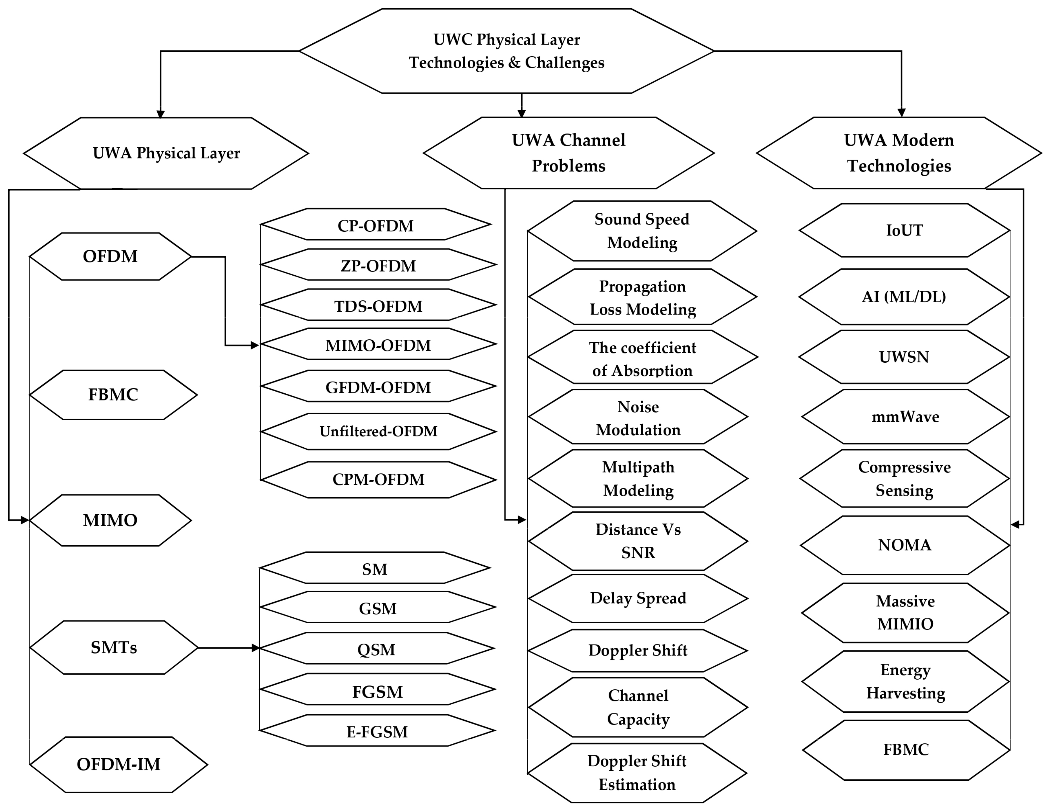
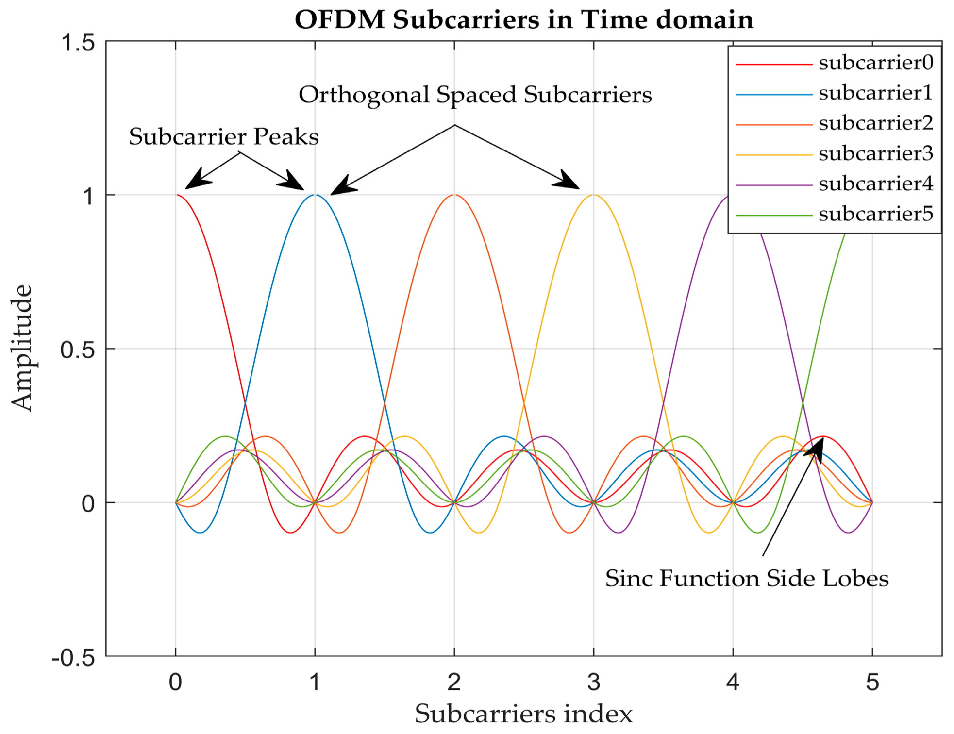
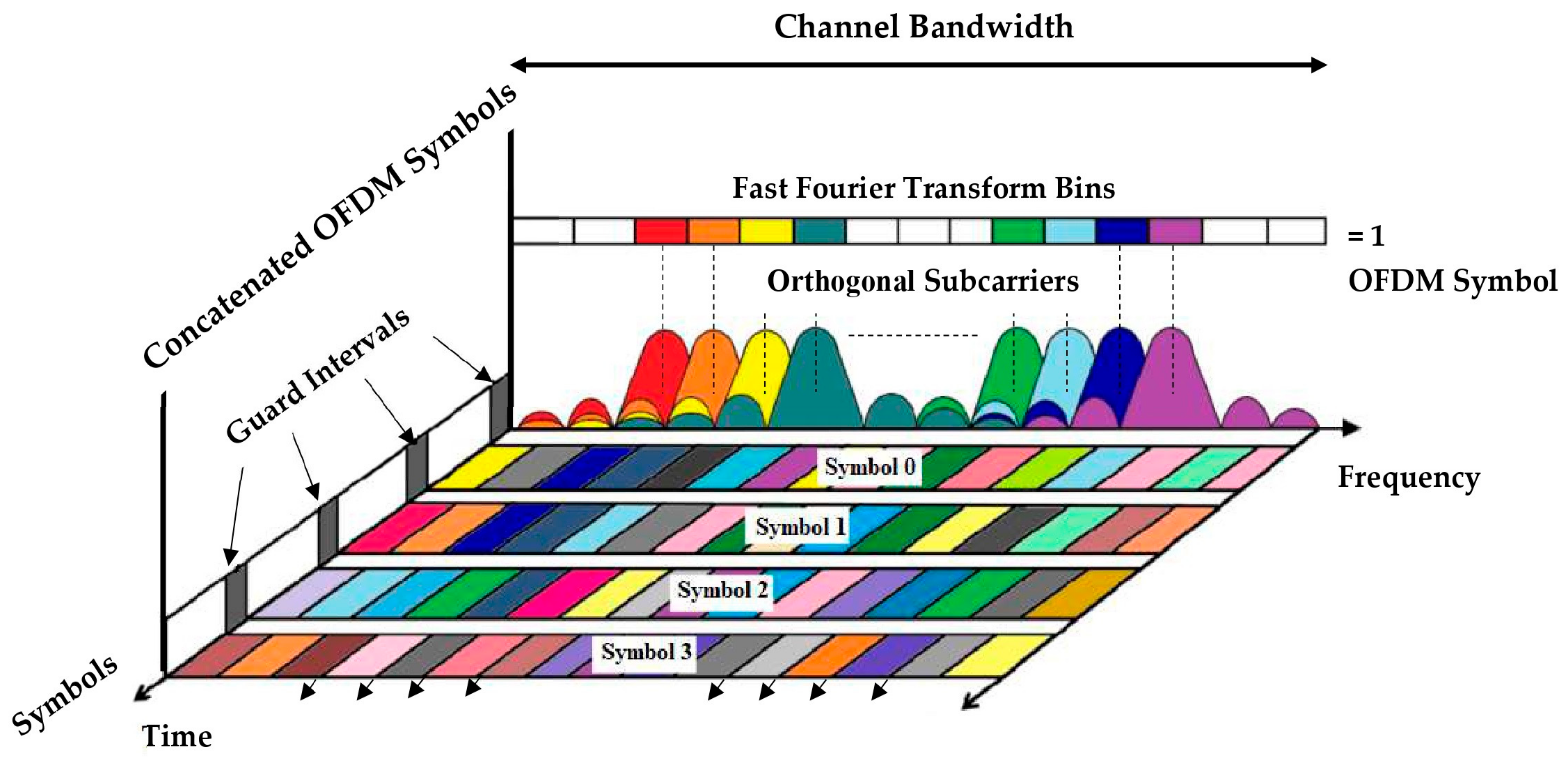
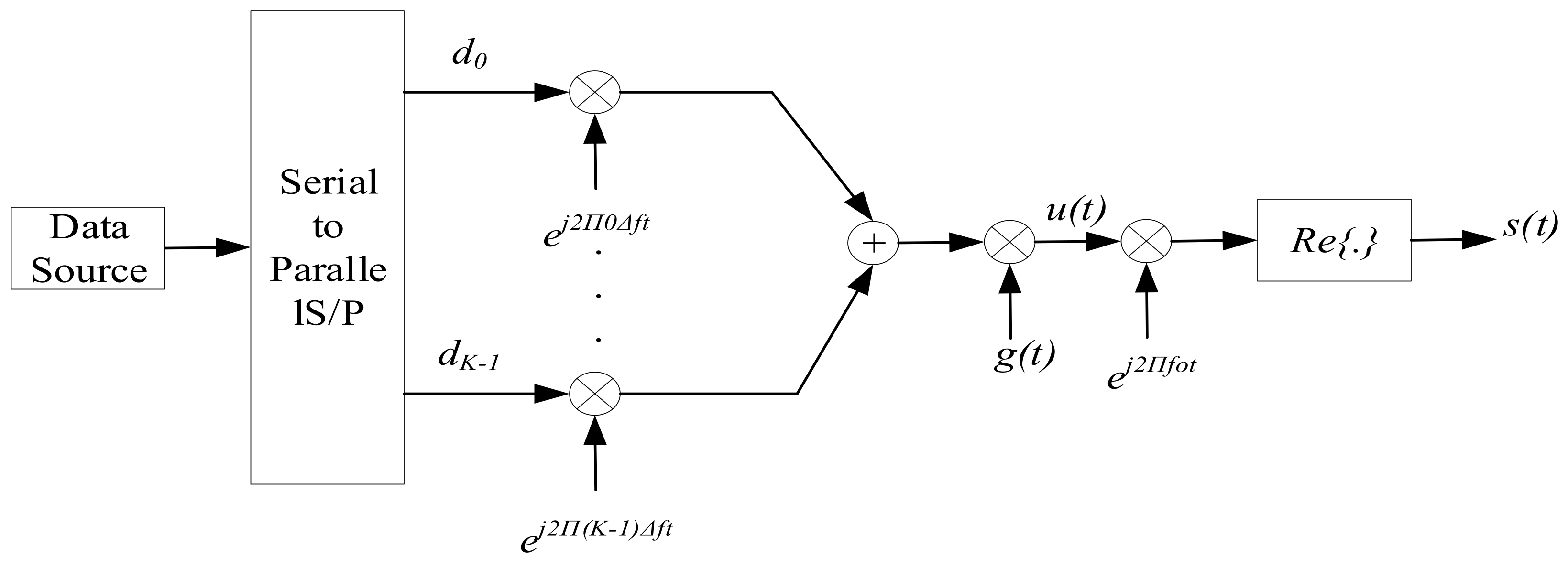
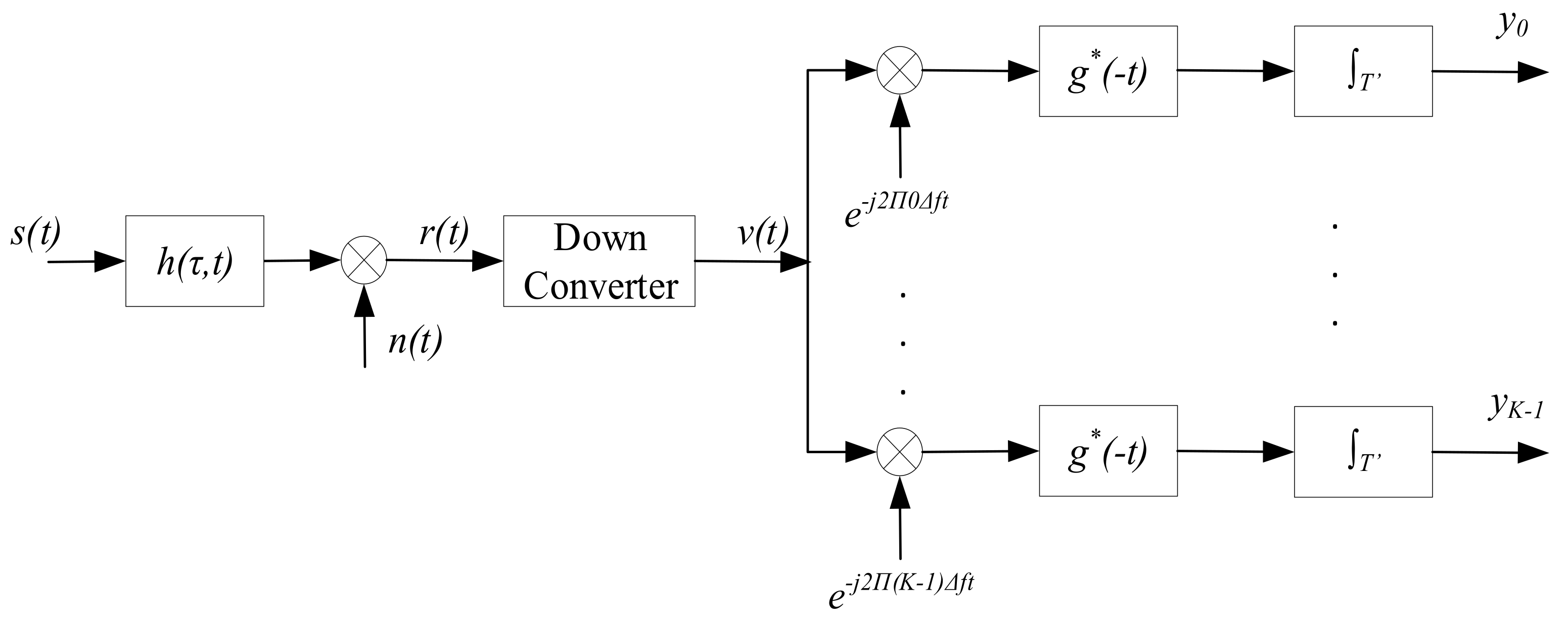
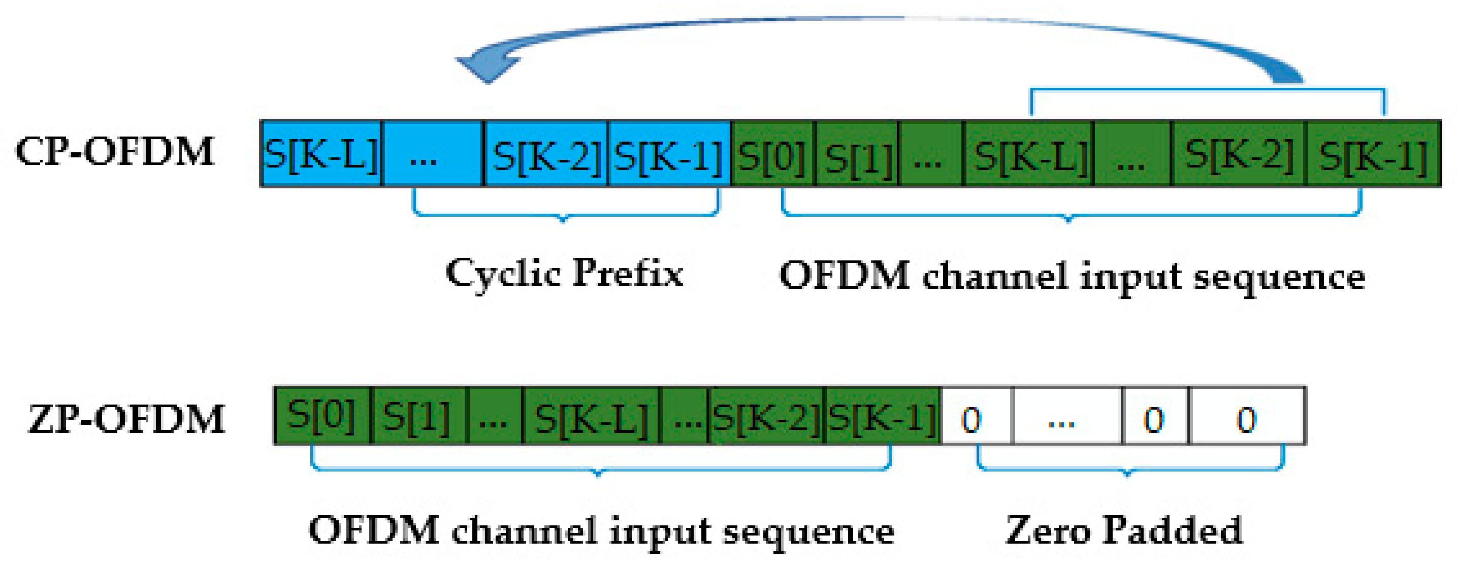
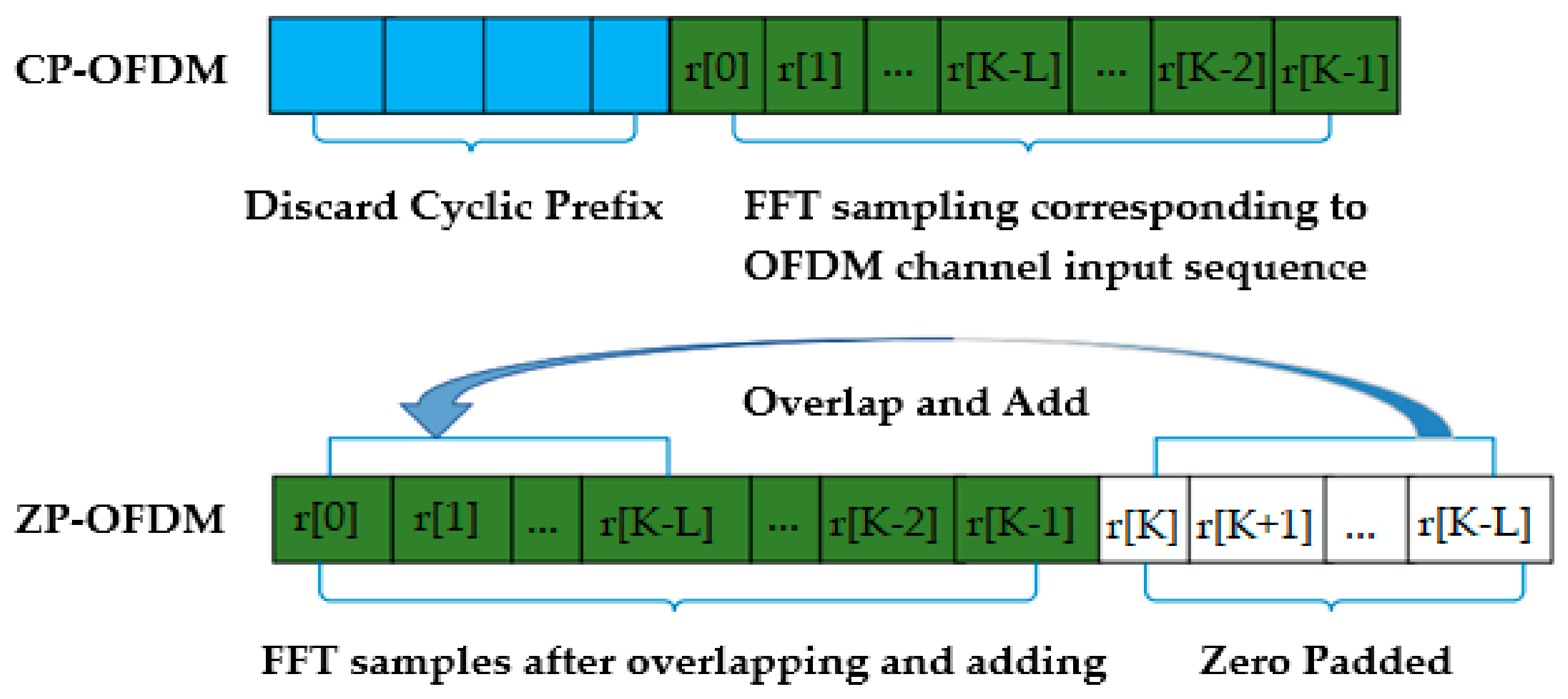
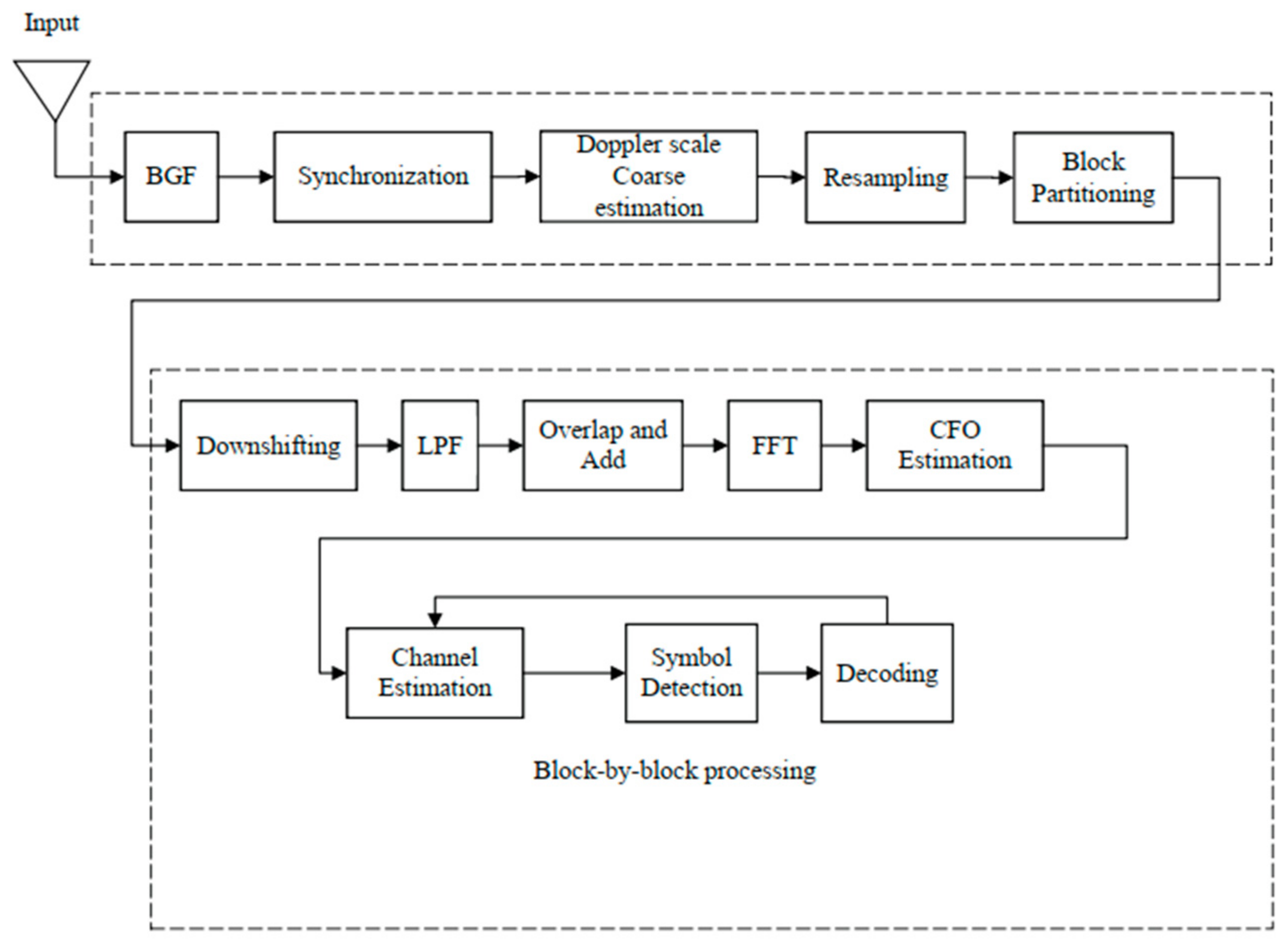
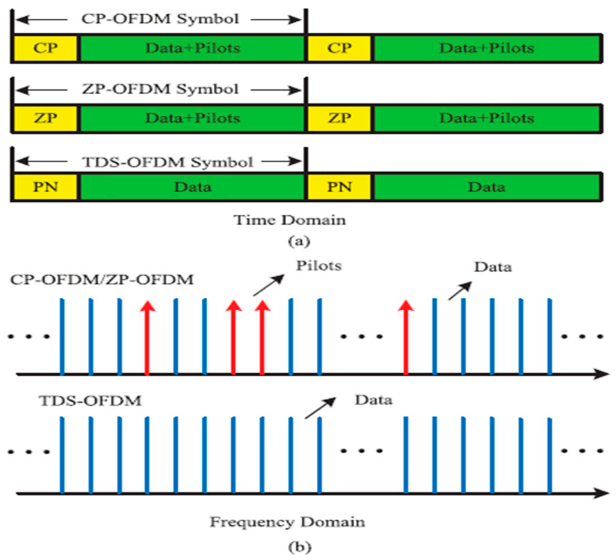
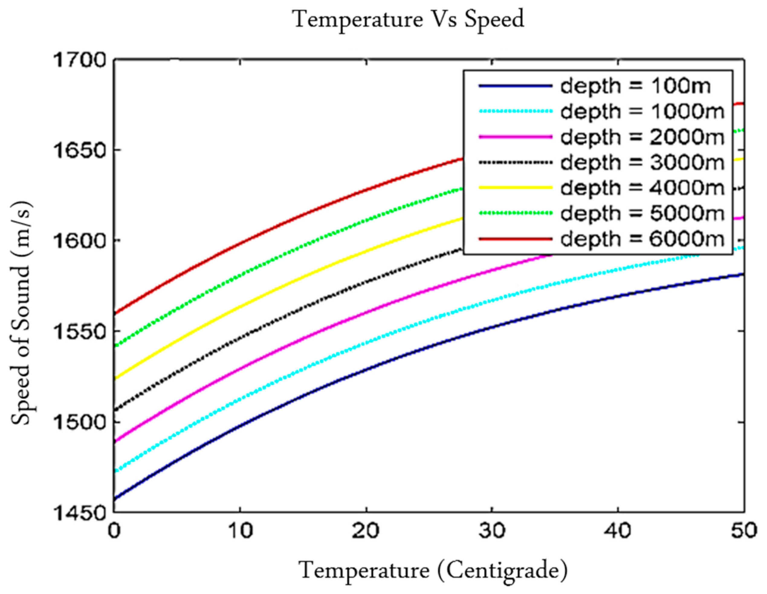
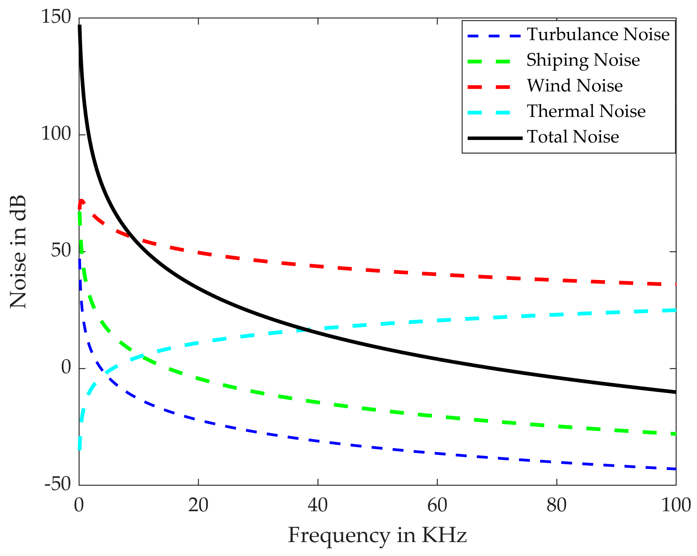
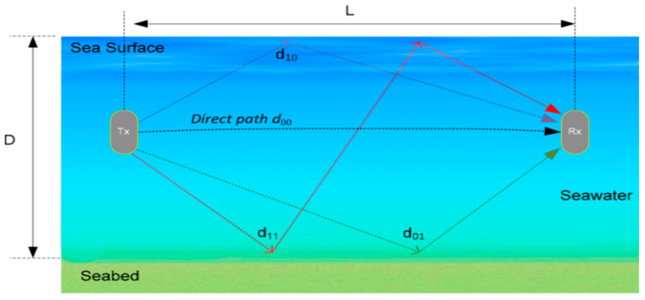
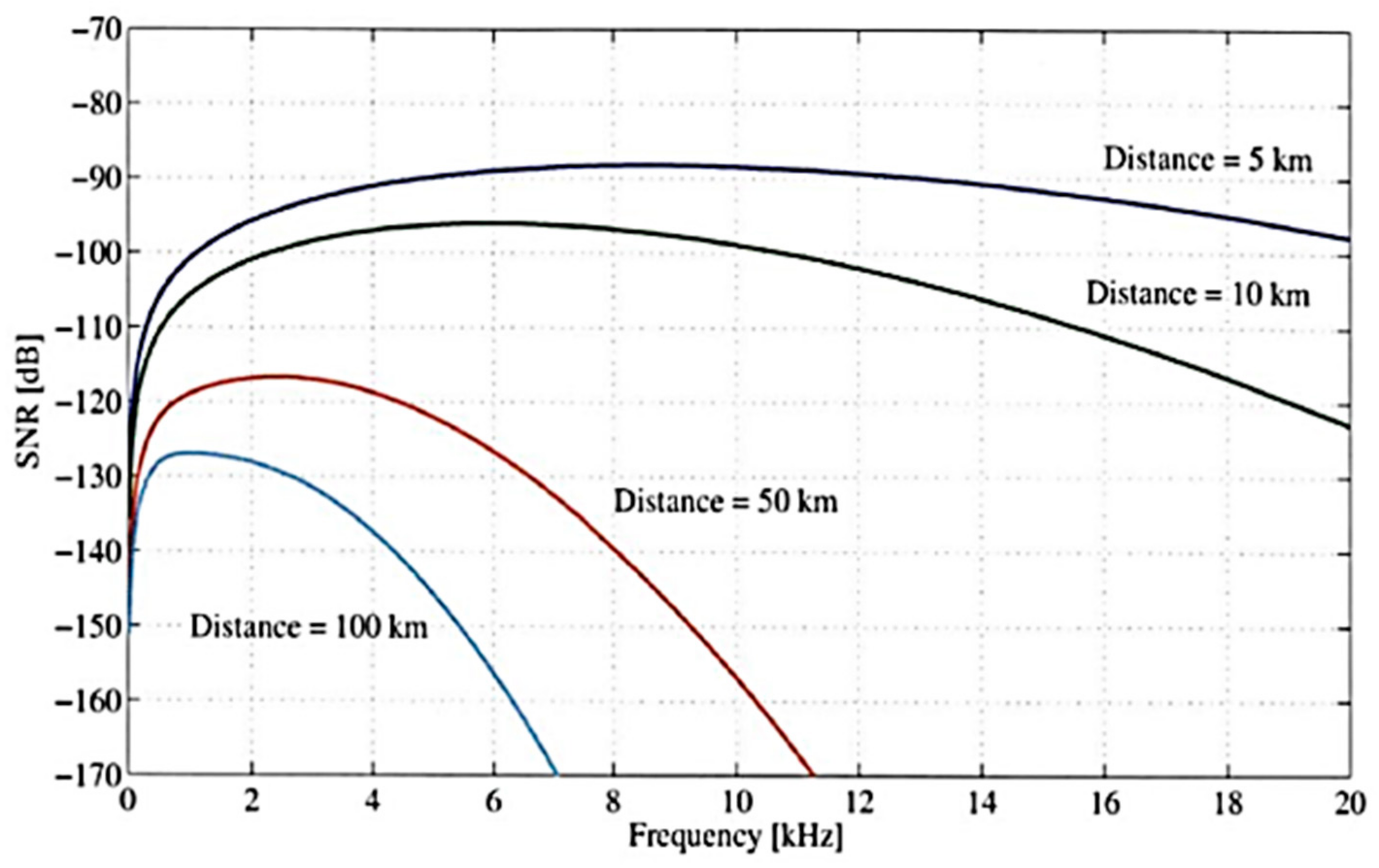
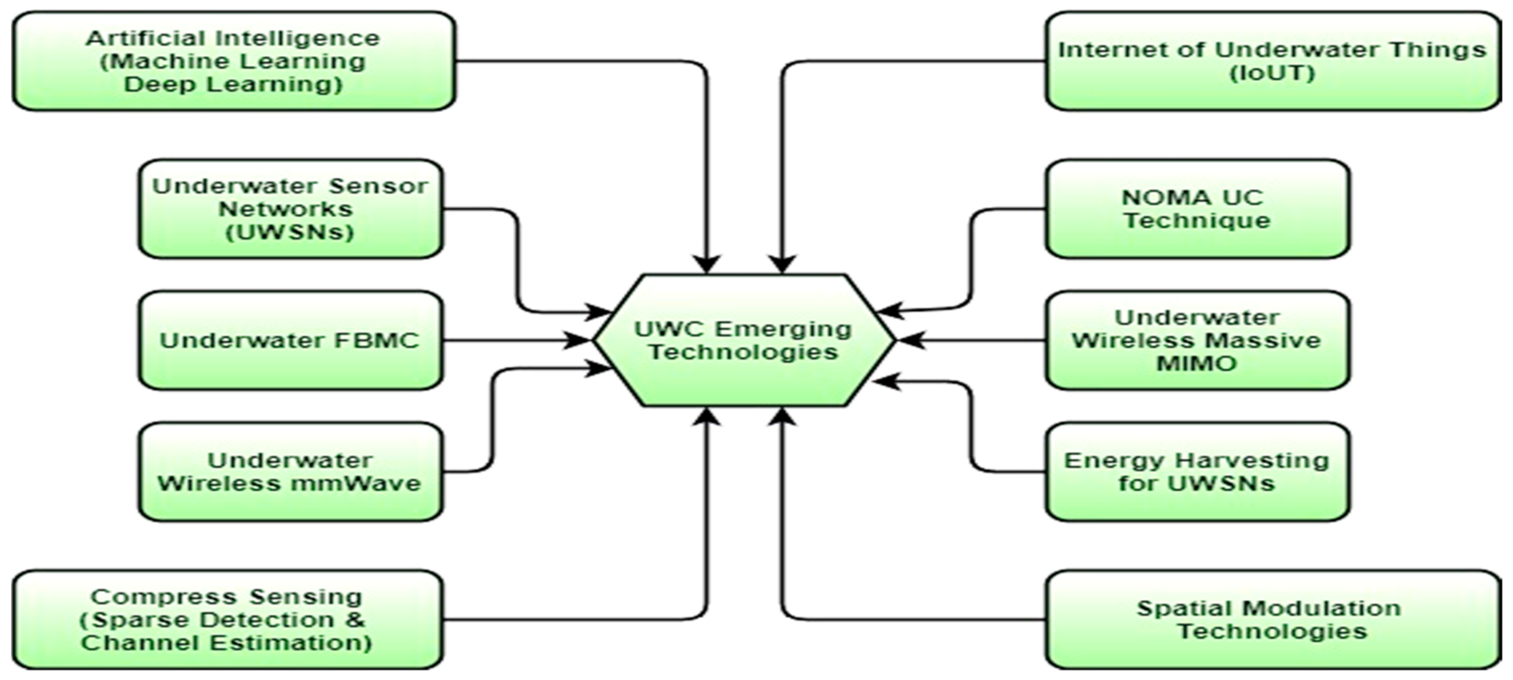