
Numerical and Experimental Study on NOx Reduction According to the Load in the SCR System of a Marine Boiler

Abstract
:1. Introduction
2. Methodology
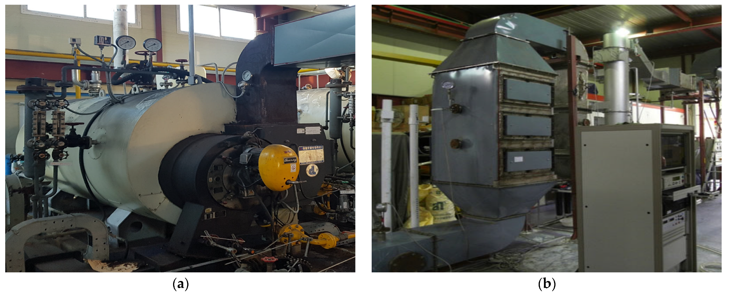
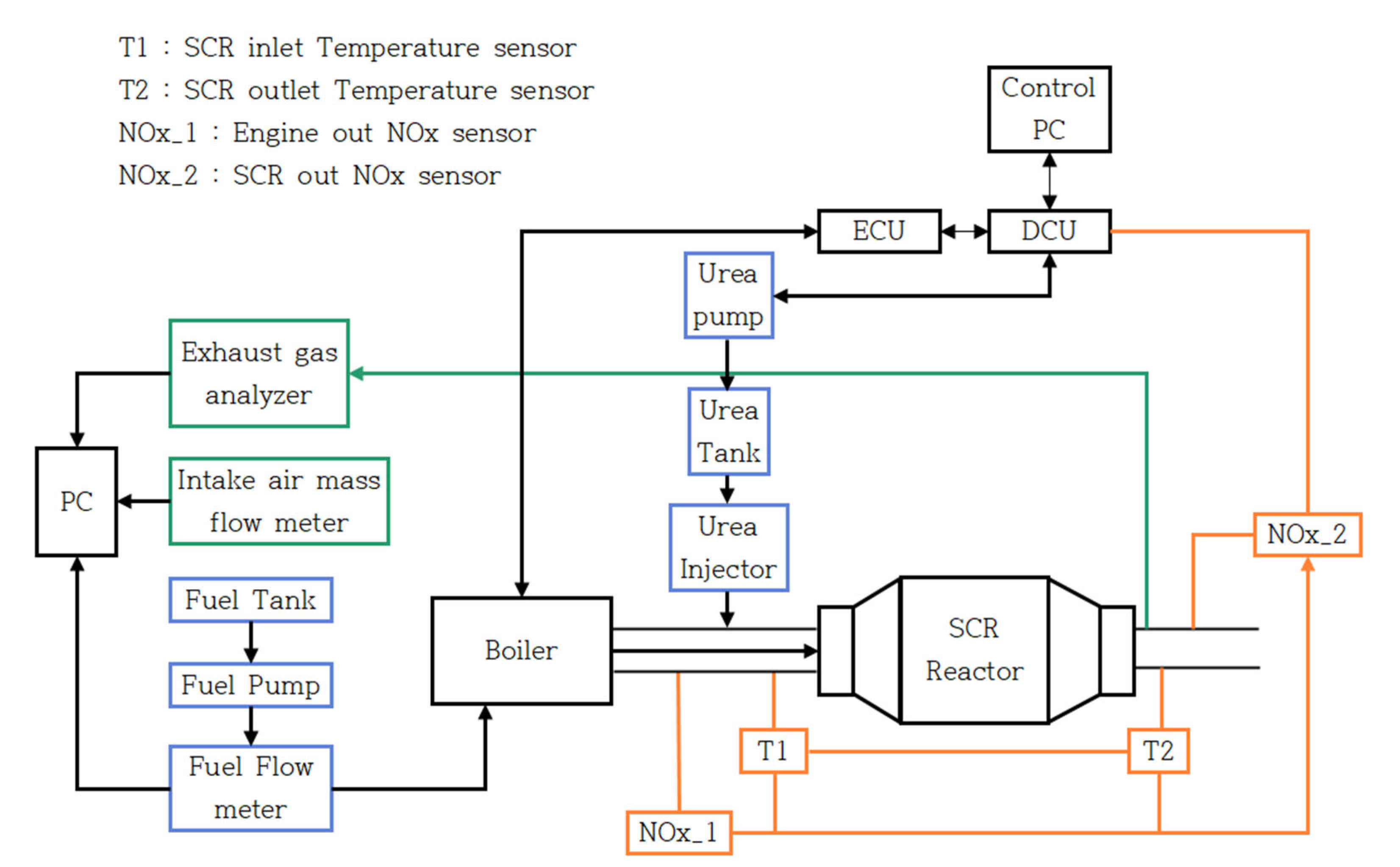
2.1. Experimental Apparatus
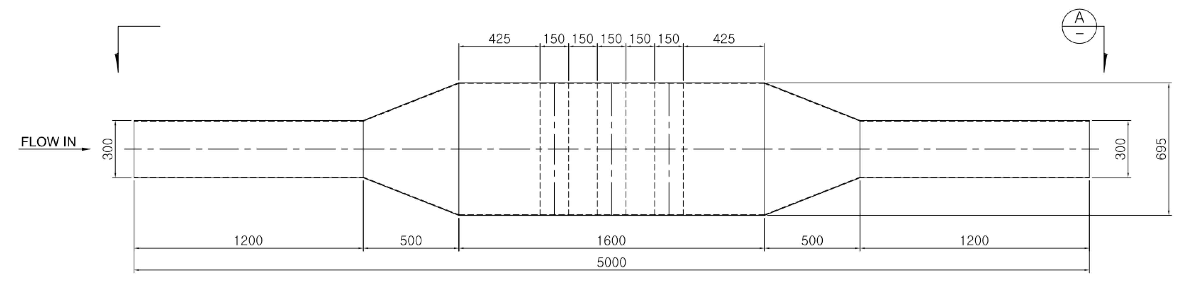
2.2. Numerical Analysis
3. Results
3.1. Diesel Fuel
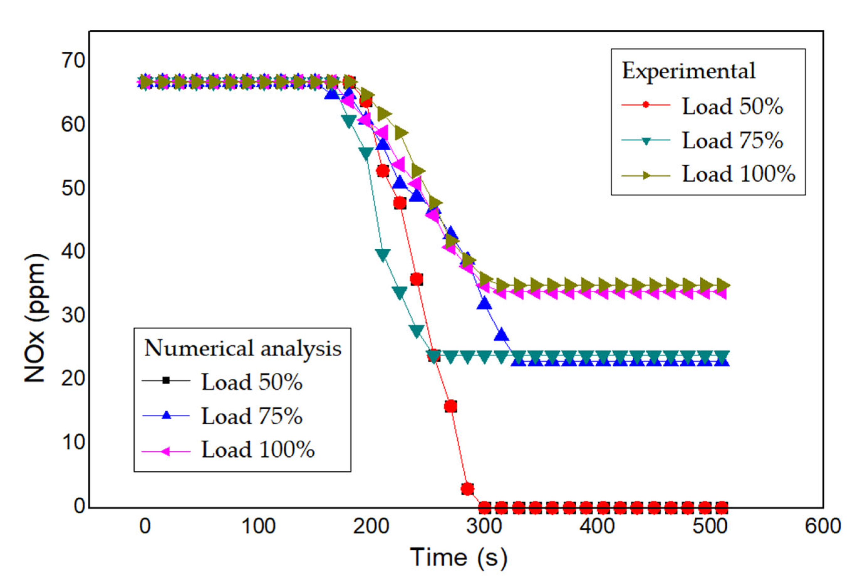
3.2. LNG Fuel
4. Conclusions
- (1)
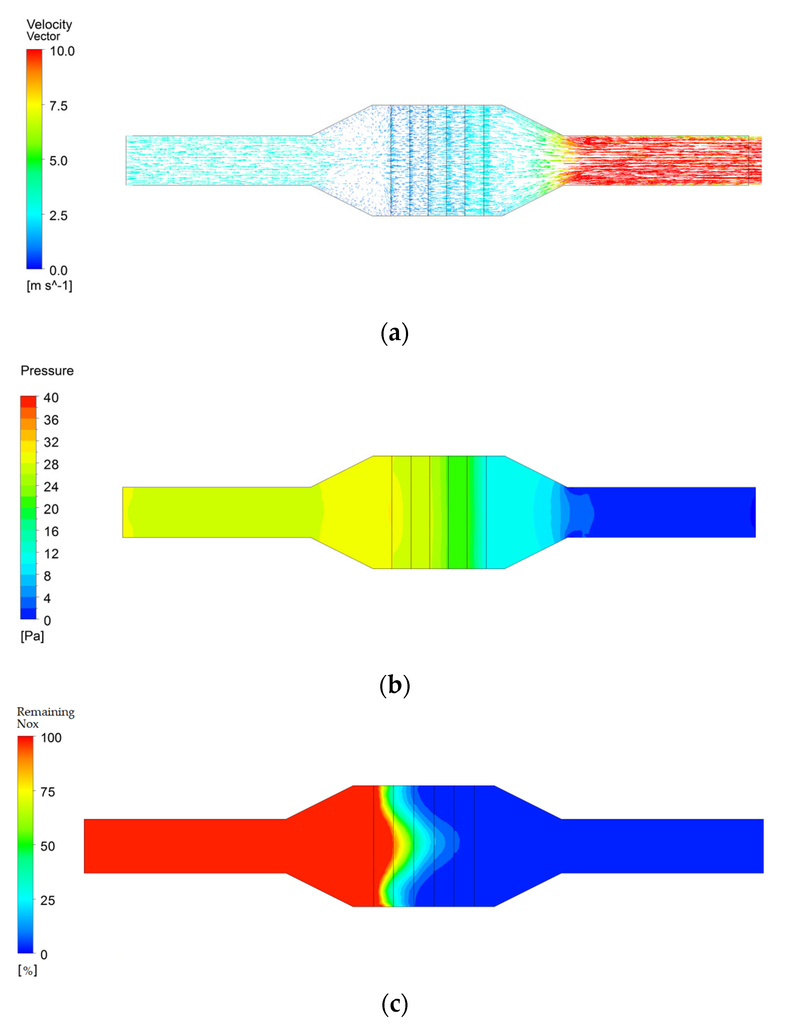
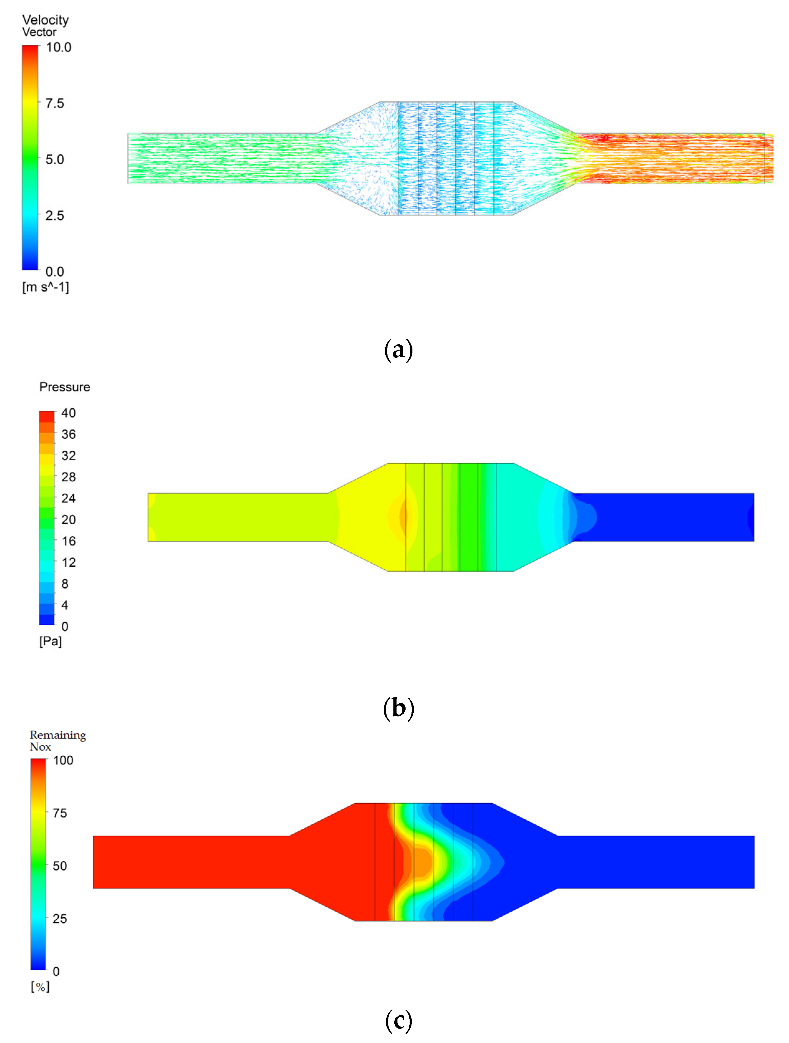
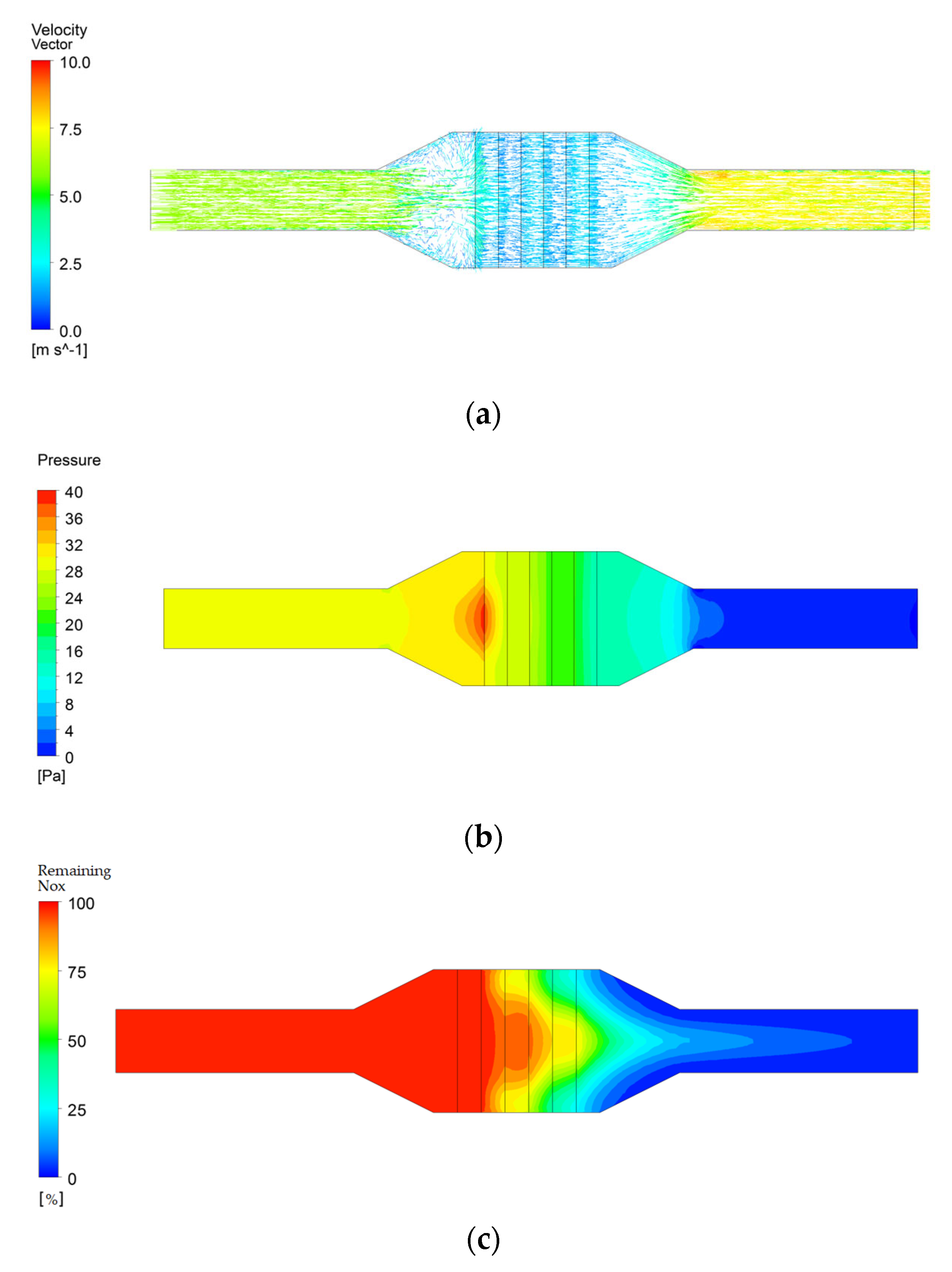
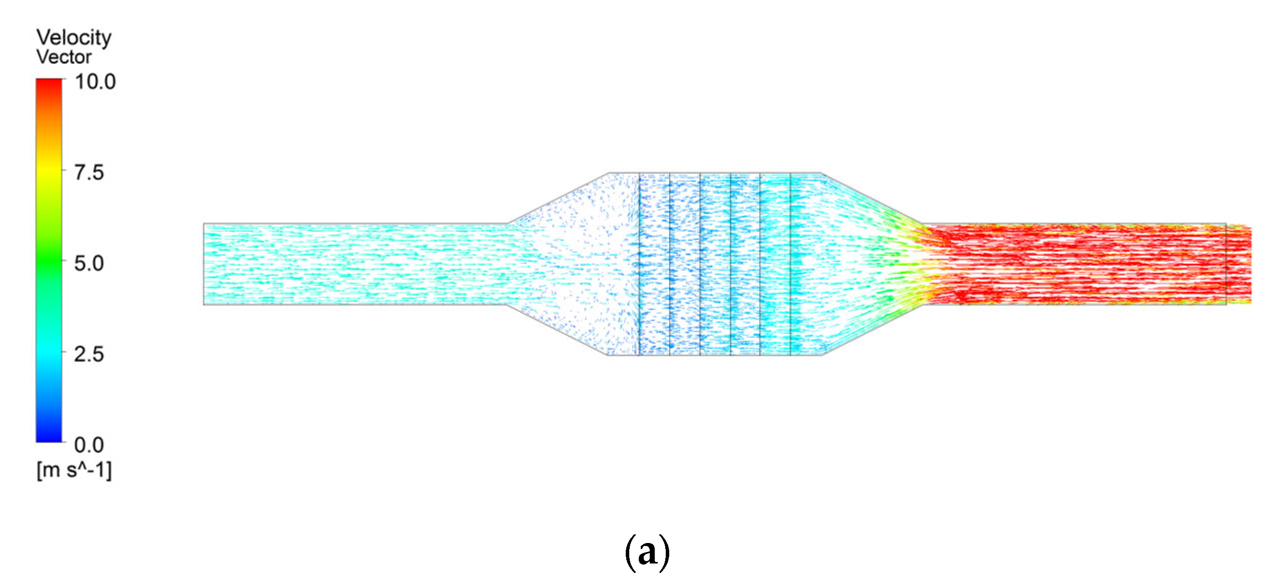
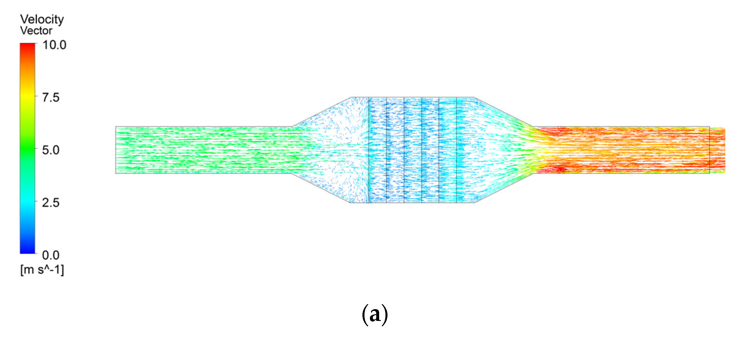
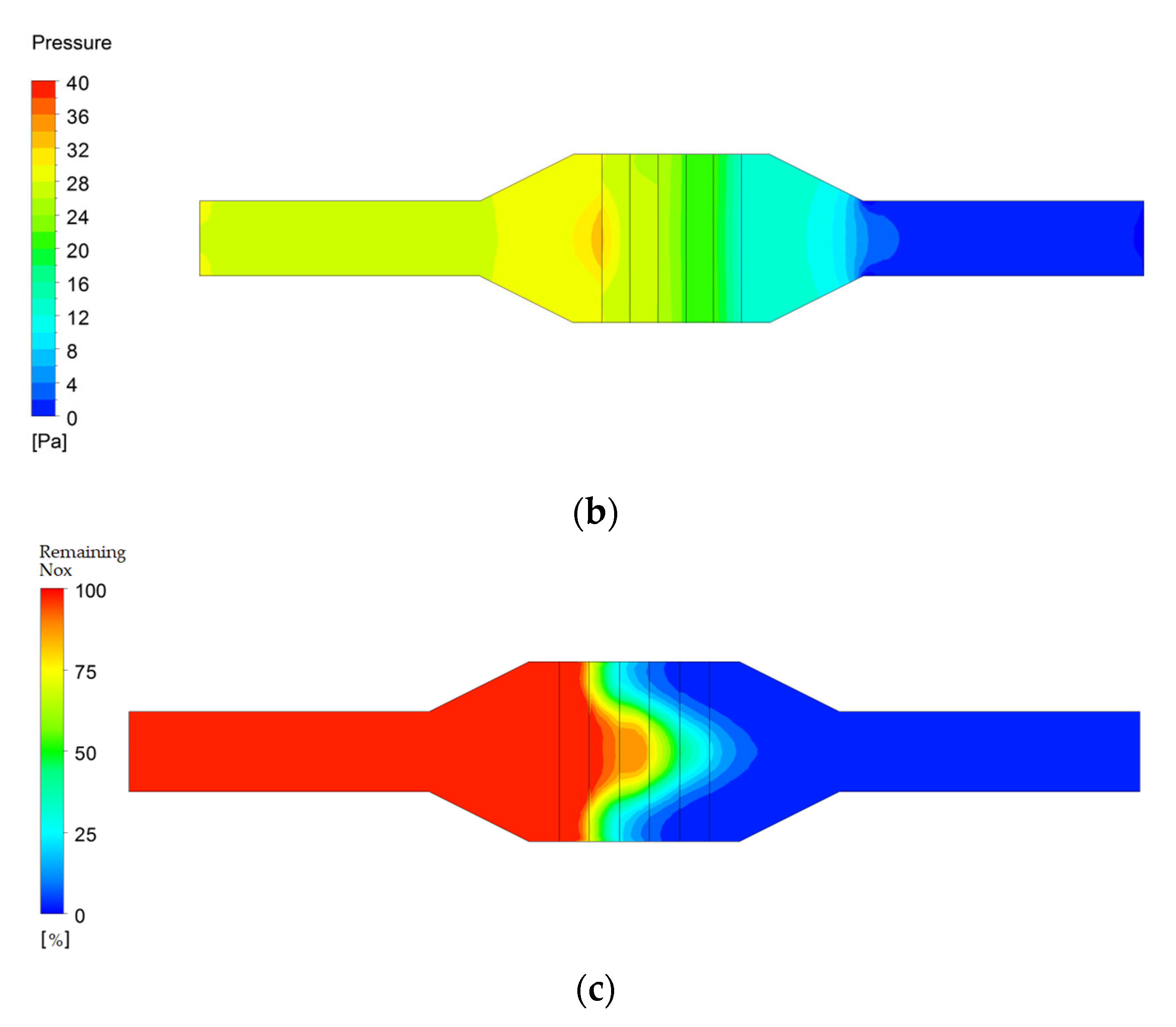
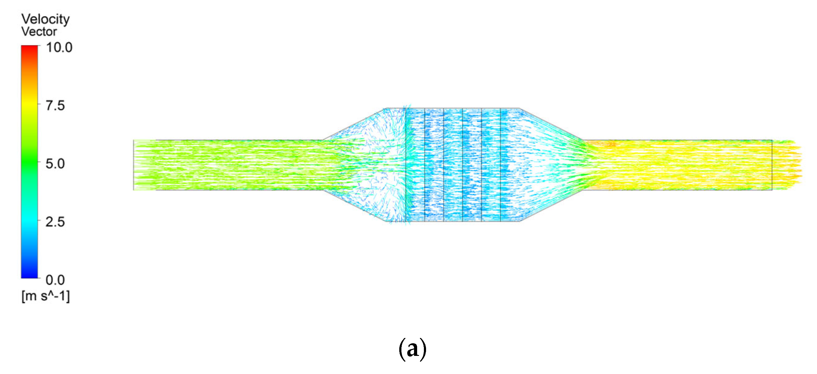
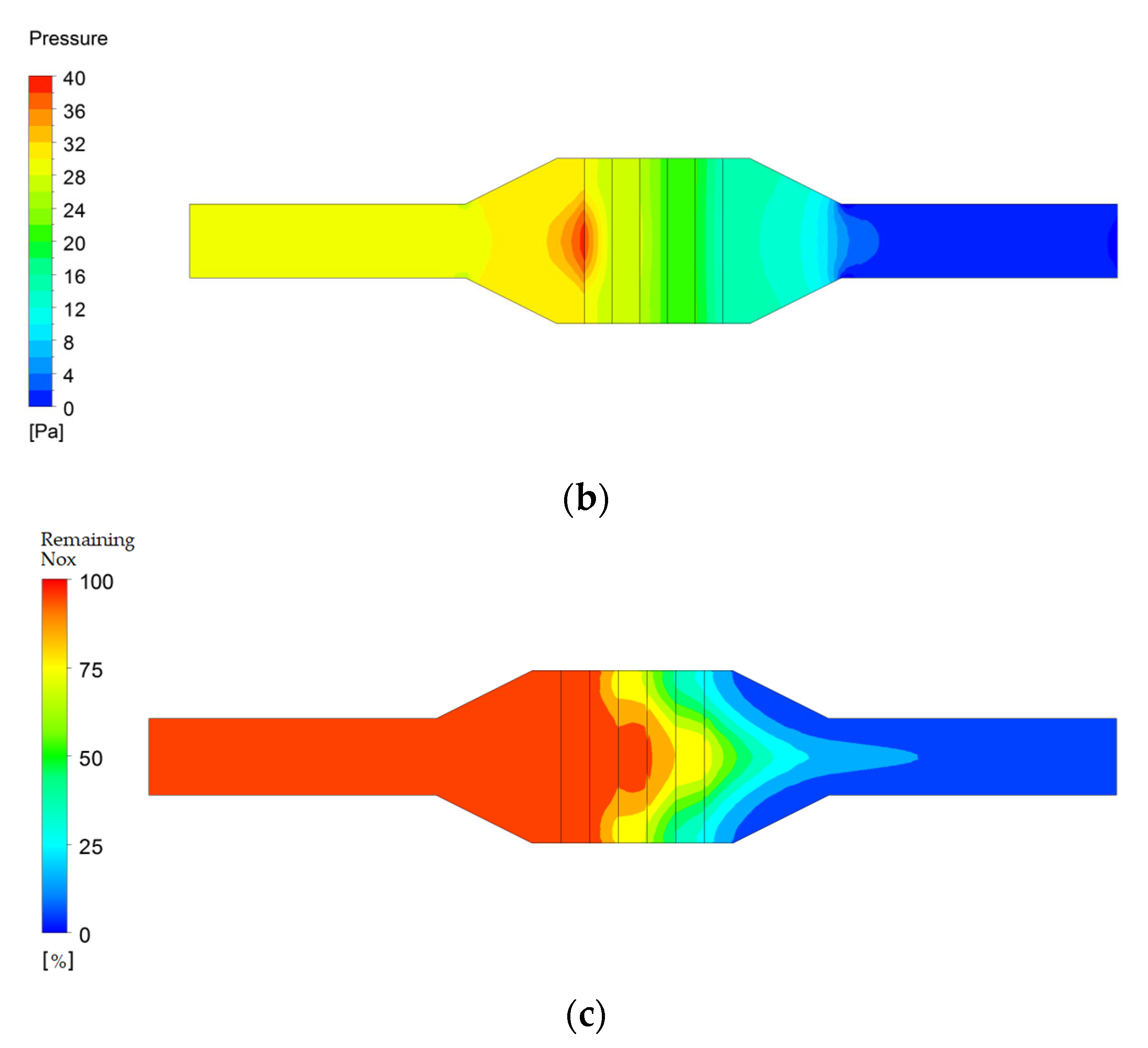
- The flow velocity of diesel fuel and LNG fuel by boiler load was maintained constant at 2.5–3 m/s. In the case of diesel fuel, the flow velocity through the outlet of the SCR system was constant at 10 m/s. In the case of LNG fuel, when the boiler load was 50%, the outlet velocity was 10 m/s. When the boiler load was 75%, the outlet velocity was 7.5–10 m/s. When the boiler load was 100%, the outlet velocity was 7.5 m/s. Therefore, it was found that as the boiler load increased, the flow velocity through the outlet decreased. Furthermore, the pressure of the SCR system was reduced to 28 Pa at the inlet and to 0 Pa at the outlet when diesel fuel was used. When LNG fuel was used, the inlet pressure was reduced to 32 Pa, and the outlet pressure was reduced equally to 0 Pa.
- (2)
- When the boiler load was 50%, the NOx emissions of diesel fuel and LNG fuel decreased by 100% to 0 ppm. When the load ratio was 75%, the NOx emissions of diesel fuel were reduced by 77.4% to 40 ppm, and for LNG fuel, they were reduced by 64.1% to 24 ppm. At a load ratio of 100%, the NOx emissions of diesel fuel were reduced by 66.1% to 60 ppm, and those of LNG fuel were reduced by 47.8% to 24 ppm. Therefore, it was found that the NOx reduction rate of diesel fuel according to the boiler load was higher than the NOx reduction rate of LNG fuel.
- (3)
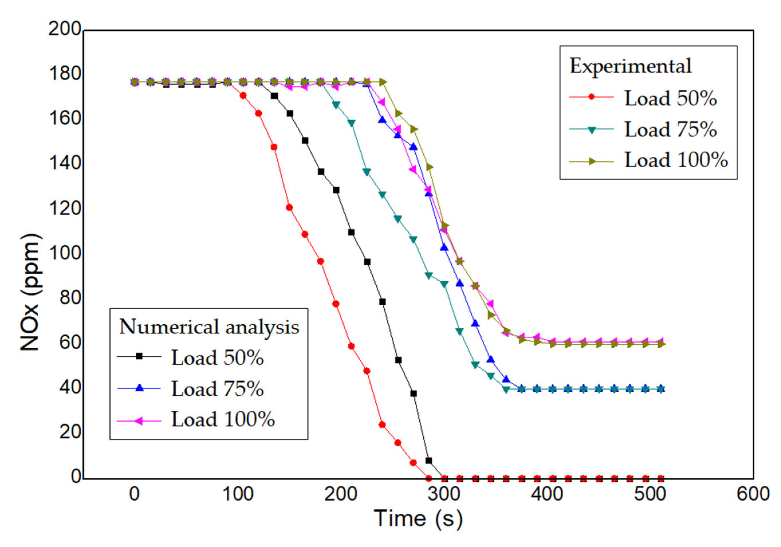
- The NOx reduction rate was examined by performing a comparative analysis between the numerical analysis and experiments of the boiler SCR system, according to diesel fuel and LNG fuel under boiler loads of 50%, 75%, and 100%. The urea injection rates were 300 g/h and 160 g/h, respectively. When diesel fuel was used, the difference in catalytic reaction time between the numerical analysis and experimental results occurred when the boiler loads were 50%, 75%, and 100%. When LNG fuel was used, a difference in catalytic reaction time occurred at boiler loads of 75% and 100%. Therefore, it was found that the numerical analysis and experimental results were almost identical. In other words, this study designed an optimal SCR system through numerical analysis, according to the important parameters of the SCR system. Therefore, the findings of this study are applicable to the design of an efficient SCR system for LNG ships. In addition, it was expected that it could be used for research and development to miniaturize the SCR system so that it could be applied to small ships.
Author Contributions
Funding
Institutional Review Board Statement
Informed Consent Statement
Data Availability Statement
Conflicts of Interest
References
- You, E.S.; Hong, S.G.; Choi, J.H. A Study on the Development Strategy for the R&D in Science Field to Respond to the Climate Change; Technical Report GOVP1200819280; The Meteorological Administration: Seoul, Republic of Korea, 2008. [Google Scholar]
- Chung, Y.A.; Chung, H.S.; Ryu, C.S. The Present Status and Development Plan in the Field of Climate Change Science in Korea Analyzed by the IPCC-IV Reports. J. Chosun Nat. Sci. 2011, 4, 38–44. [Google Scholar]
- IPCC. IPCC-4, 2007: IPCC-4 Assessment Report-4(AR-4). In Climate Change 2007: Working Group II Report, “Impacts, Adatation and Vulnerability”; IPCC: Geneva, Switzerland, 2007; p. 938. [Google Scholar]
- IPCC. IPCC-4, IPCC-4 Assessment Report-4(AR-4). In Climate Change 2007: Working Group III Report “Mitigation of Climate Change”; IPCC: Geneva, Switzerland, 2007; p. 854. [Google Scholar]
- Fet, A.M.; Sorgard, E. Life cycle evaluation of ship transportation: Development of methodology and testing, DNV research report, Norway. 1998; unpublished. [Google Scholar]
- Ellingsen, H.; Fet, A.M.; Aanondsen, S. Tool for Environmental Efficient Ship Design; Norway University: Notodden, Norway, 2002. [Google Scholar]
- Park, M.H.; Lee, C.M.; Antony, J.N.; Jang, H.J.; Choi, J.H.; Hur, J.J.; Lee, W.J. Prediction of Emission Characteristics of Generator Engine with Selective Catalytic Reduction Using Artificial Intelligence. J. Mar. Sci. Eng. 2022, 10, 118. [Google Scholar] [CrossRef]
- Im, N.K.; Jo, H.J. The inventory analysis on exhaust gas from training ships for ship’s LCA study. J. Navig. Port Res. 2008, 32, 29–35. [Google Scholar] [CrossRef] [Green Version]
- Im, N.K.; Yi, S.R. An inventory analysis on greenhouse gas emission from bulk carrier and oil tanker. J. Navig. Port Res. 2010, 34, 189–194. [Google Scholar] [CrossRef] [Green Version]
- Lee, H.S.; Park, J.C.; Cho, Y.J.; Jeong, S.M.; Yu, J.S. Comprehensive environmental impact assessment for CO2 emitted from sailing ship. J. Korean Soc. Mar. Environ. Energy 2013, 16, 181–188. [Google Scholar] [CrossRef]
- Forzatti, P. Present status and perspectives in de-NOx SCR catalysis; Dipartimento di Chimica Industriale e Ingegneria Chimica “G. Natta”. Appl. Catal. Ageneral 2001, 222, 221–236. [Google Scholar] [CrossRef]
- Kim, D.K.; Lee, C.H. SCR Performance Evaluations in Relation to Experimental Parameters in a Marine Generator Engine. J. Mar. Sci. Eng. 2019, 7, 67. [Google Scholar] [CrossRef] [Green Version]
- Shamun, S.; Belgiorno, G.; Blasio, G.D.; Beatrice, C.; Tuner, M.; Tunestal, P. Performance and emissions of diesel-biodiesel-ethanol blends in a light duty compression ignition engine. Appl. Therm. Eng. 2018, 145, 444–452. [Google Scholar] [CrossRef]
- Gilberto, F.G.; Rodolfo, S.E.; Jose, M.B.R.; Jonathan, D.W.K.; Rafael, E.A.D. Review of Top-Down Method to Determine Atmospheric Emissions in Port. Case of Study: Port of Veracruz, Mexico. J. Mar. Sci. Eng. 2022, 10, 96. [Google Scholar]
- Lee, M.W.; Lee, H.S. Estimation of ship emissions and environmental costs: Focusing on Port of Busan. J. Korea Port Econ. Assoc. 2016, 32, 15–28. [Google Scholar]
- Wu, P.C.; Lin, C.Y. Strategies for the Low Sulfur Policy of IMO—An Example of a Container Vessel Sailing through a European Route. J. Mar. Sci. Eng. 2021, 9, 1383. [Google Scholar] [CrossRef]
- Kazimierz, W. Research of the Effectiveness of Selected Methods of Reducing Toxic Exhaust Emissions of Marine Diesel Engines. J. Mar. Sci. Eng. 2020, 8, 452. [Google Scholar]
- IMO Marine Environment Protection Committee, 72nd Session. Available online: http://www.imo.ord (accessed on 20 April 2018).
- Fan, H.J.; Tu, H.; Hossein, E.; Xu, X.Y.; Wei, Y. Comparison of the Economic Performances of Three Sulphur Oxides Emissions Abatement Solutions for a Very Large Crude Carrier (VLCC). J. Mar. Sci. Eng. 2021, 9, 221. [Google Scholar] [CrossRef]
- Lee, J.H.; Kwak, J.S. Marine generator system for reduction in air pollutants. Ransactions Korean Soc. Mech. Eng. A 2018, 42, 939–944. [Google Scholar] [CrossRef]
- Lu, D.; Theotokatos, G.; Zhang, J.; Zeng, H.; Cui, K. Comparative Assessment and Parametric Optimisation of Large Marine Two-Stroke Engines with Exhaust Gas Recirculation and Alternative Turbocharging Systems. J. Mar. Sci. Eng. 2022, 10, 351. [Google Scholar] [CrossRef]
- Lee, T.H.; Lee, S.H.; Lee, J.K. Exhaust Gas Emission Improvements of Water/Bunker C Oil-Emulsified Fuel Applied to Marine Boiler. J. Mar. Sci. Eng. 2021, 9, 477. [Google Scholar] [CrossRef]
- Lee, M.W.; Lee, H.S. A study on atmospheric dispersion pattern of ship emissions—Focusing on Port of Busan. J. Korea Port Econ. Assoc. 2018, 34, 35–50. [Google Scholar] [CrossRef]
- Park, Y.T.; Kim, I.G. A Study on the Green Port Construction Strategy of Busan Port through Reducing Air Pollution in the Eco-Friendly Era; Dong-Eui University: Busan, Republic of Korea, 2014; Volume 10, pp. 263–284. [Google Scholar]
- Kraipat, C.; Chedthawut, P.; Choi, G.H. Performance and emissions of a heavy-duty diesel engine fuelled with diesel and LNG (liquid natural gas). Energy 2013, 53, 52–57. [Google Scholar]
- Van, C.P.; Rho, B.S.; Kim, J.S.; Lee, W.J.; Choi, J.H. Effects of Various Fuels on Combustion and Emission Characteristics of a Four-Stroke Dual-Fuel Marine Engine. J. Mar. Sci. Eng. 2021, 9, 1072. [Google Scholar]
- Ianniello, R.; Di Blasio, G.; Marialto, R.; Beatrice, C.; Cardone, M. Assessment of Direct Injected Liquefied Petroleum Gas-Diesel Blends for Ultra-Low Soot Combustion Engine Application. Appl. Sci. 2020, 10, 4949. [Google Scholar] [CrossRef]
- Maja, P.; Nikola, V.; Ailong, F.; Ivana, J. Holistic Energy Efficiency and Environmental Friendliness Model for Short-Sea Vessels with Alternative Power Systems Considering Realistic Fuel Pathways and Workloads. J. Mar. Sci. Eng. 2022, 10, 613. [Google Scholar]
- Beidong, Z.; Yankun, J.; Yexin, V. Research on Calibration, Economy and PM Emissions of a Marine LNG–Diesel Dual-Fuel Engine. J. Mar. Sci. Eng. 2022, 10, 239. [Google Scholar]
- Yun, S.K. Characteristics of boil-off-gas partial re-liquefaction system in LNG ships. J. Adv. Mar. Eng. Technol. 2016, 40, 174–179. [Google Scholar] [CrossRef]
- Miana, M.; Legorburo, R.; Diez, D.; Hwang, Y.B. Calculation of boil-off rate of liquefied natural gas in mark III tanks of ship carriers by numerical analysis. Appl. Therm. Eng. 2016, 93, 279–296. [Google Scholar] [CrossRef]
- Lee, J.-U.; Choi, Y.-J.; Hwang, S.-C.; Han, S.-H. A Study on the Numerical Analysis of the SCR system in a 1.5 Ton Marine Boiler. J. Power Syst. Eng. 2022, 26, 21–29. [Google Scholar] [CrossRef]


| Test Condition | Value |
|---|---|
| Design pressure (kg/cm2) | 10 |
| Max. temperature (°C) | 300 |
| Maximum flow rate (Am3/h) | 1500 |
| Convert evaporation (kg/h) | 1791 |
| Total outbreak heat cap (kcal/h) | 965,550 |
| Efficiency (%) | 88 |
| Heating surface (m2) | 35 |
| Fuel consumption, Diesel (kg/h) | 106.5 |
| Fuel consumption, LNG (kg/h) | 110.3 |
| Item | Diesel | LNG | |
|---|---|---|---|
| Inlet flow velocity (m/s) | 50% load | 3.0 | |
| 75% load | 4.5 | ||
| 100% load | 6.0 | ||
| CHO content (%) | C | 86 | 76 |
| H | 14 | 24 | |
| O | 0 | 0 | |
| Porosity | 0.7 | 0.7 | |
| Urea (g/h) | 300 | 160 | |
| IN NOx (ppm) | 177 | 67 | |
| Density (kg/m3) | 831 | 415 | |
| Specific gravity | - | 0.55 | |
| Cetane number | 40–55 | - | |
| Boiling point (°C) | 180-370 | −162 | |
| Kinematic Viscosity (mm2/s) | 3 | - | |
| Ignition point (°C) | 250 | 537 | |
| Exhaust Inlet Velocity (m/s) | 3–6 | ||
| Exhaust Temperature (°C) | 200 | ||
| Catalyst Porosity | 0.7 | ||
| Wall | No-slip | ||
| Turbulence Model | |||
Disclaimer/Publisher’s Note: The statements, opinions and data contained in all publications are solely those of the individual author(s) and contributor(s) and not of MDPI and/or the editor(s). MDPI and/or the editor(s) disclaim responsibility for any injury to people or property resulting from any ideas, methods, instructions or products referred to in the content. |
© 2023 by the authors. Licensee MDPI, Basel, Switzerland. This article is an open access article distributed under the terms and conditions of the Creative Commons Attribution (CC BY) license (https://creativecommons.org/licenses/by/4.0/).
Share and Cite
Lee, J.-U.; Hwang, S.-C.; Han, S.-H. Numerical and Experimental Study on NOx Reduction According to the Load in the SCR System of a Marine Boiler. J. Mar. Sci. Eng. 2023, 11, 777. https://doi.org/10.3390/jmse11040777
Lee J-U, Hwang S-C, Han S-H. Numerical and Experimental Study on NOx Reduction According to the Load in the SCR System of a Marine Boiler. Journal of Marine Science and Engineering. 2023; 11(4):777. https://doi.org/10.3390/jmse11040777
Chicago/Turabian StyleLee, Jeong-Uk, Sung-Chul Hwang, and Seung-Hun Han. 2023. "Numerical and Experimental Study on NOx Reduction According to the Load in the SCR System of a Marine Boiler" Journal of Marine Science and Engineering 11, no. 4: 777. https://doi.org/10.3390/jmse11040777