
Thrust Enhancement of DTMB 5415 with Elastic Flapping Foil in Regular Head Waves


Abstract
:1. Introduction
1.1. Background
1.2. Investigations Regarding Bow Foil
1.3. Paper Contribution and Outline
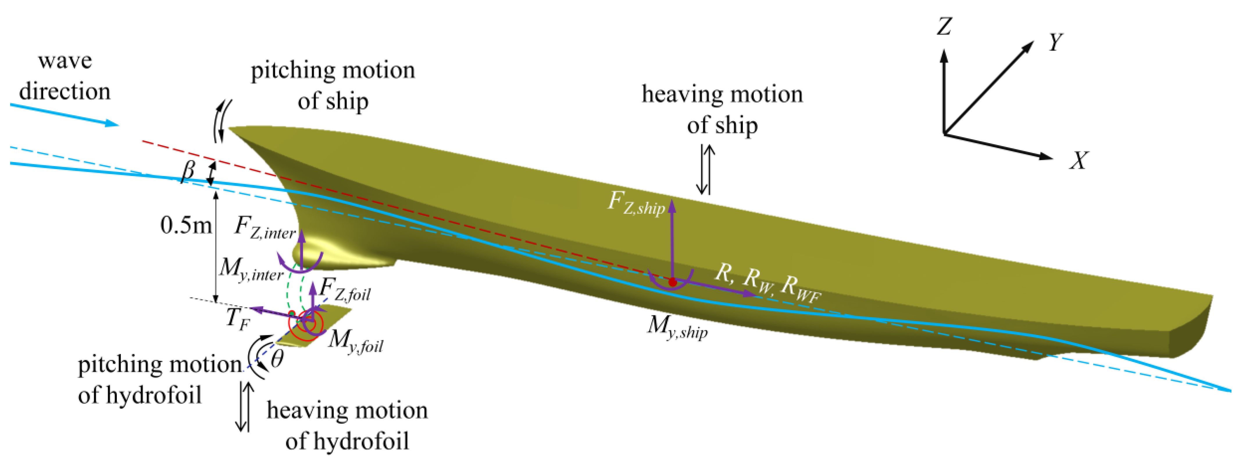
2. Ship with Semi-Passive Flapping Foil in Head Wave
3. Numerical Method
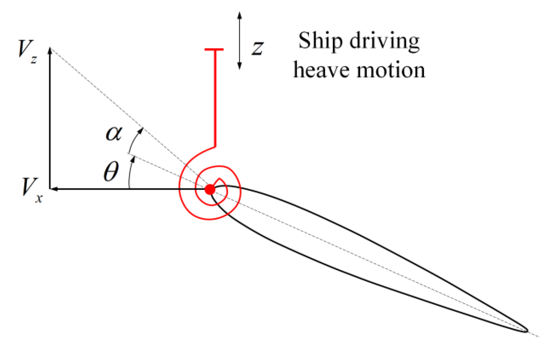
3.1. Hydrodynamic Function
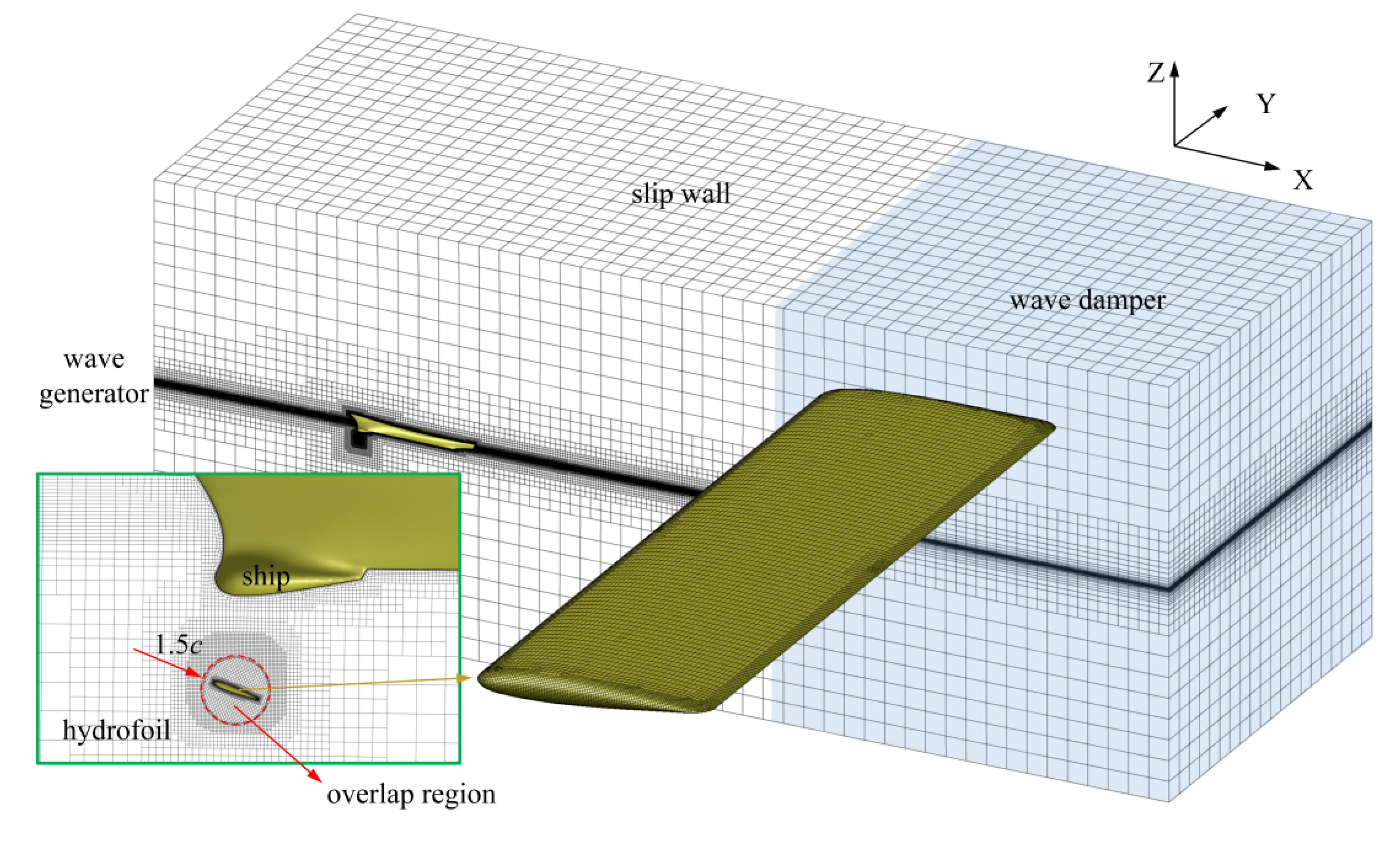
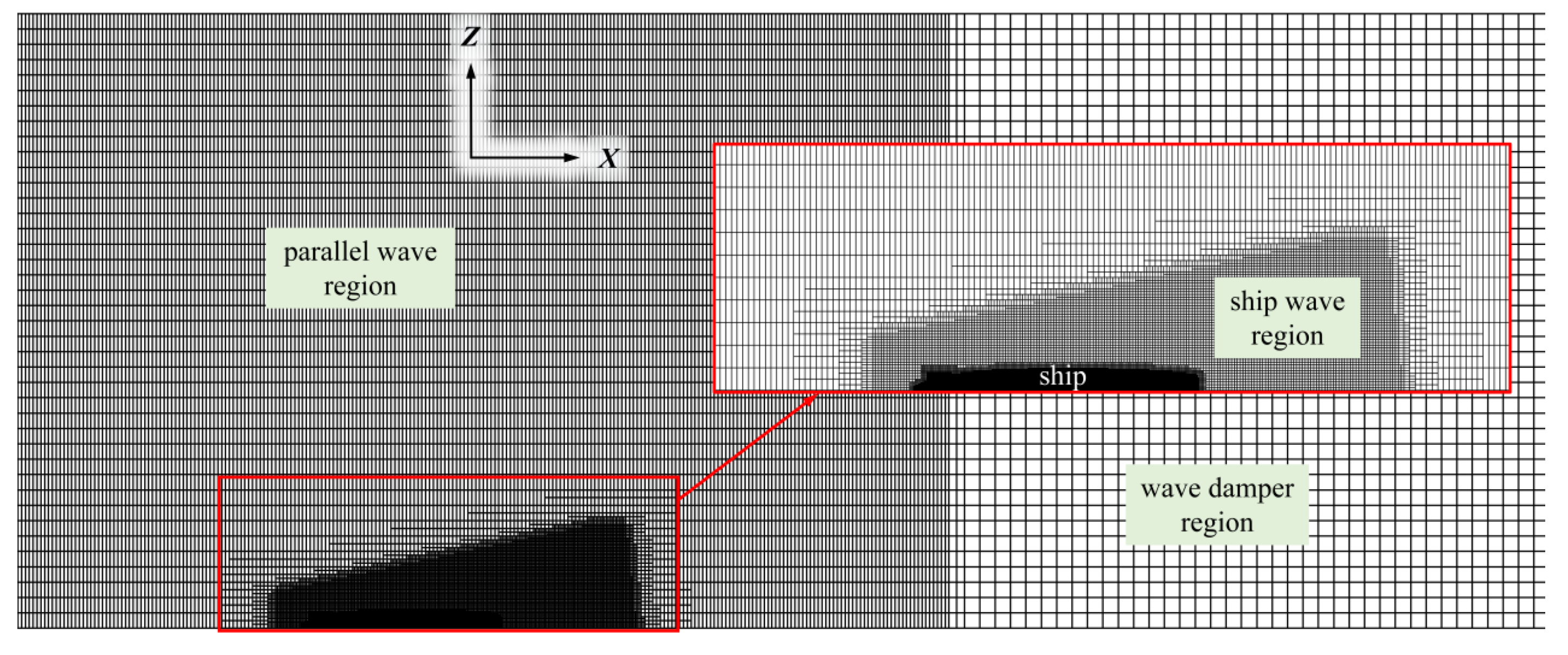
3.2. Mesh and Method
3.3. Comparison and Validation
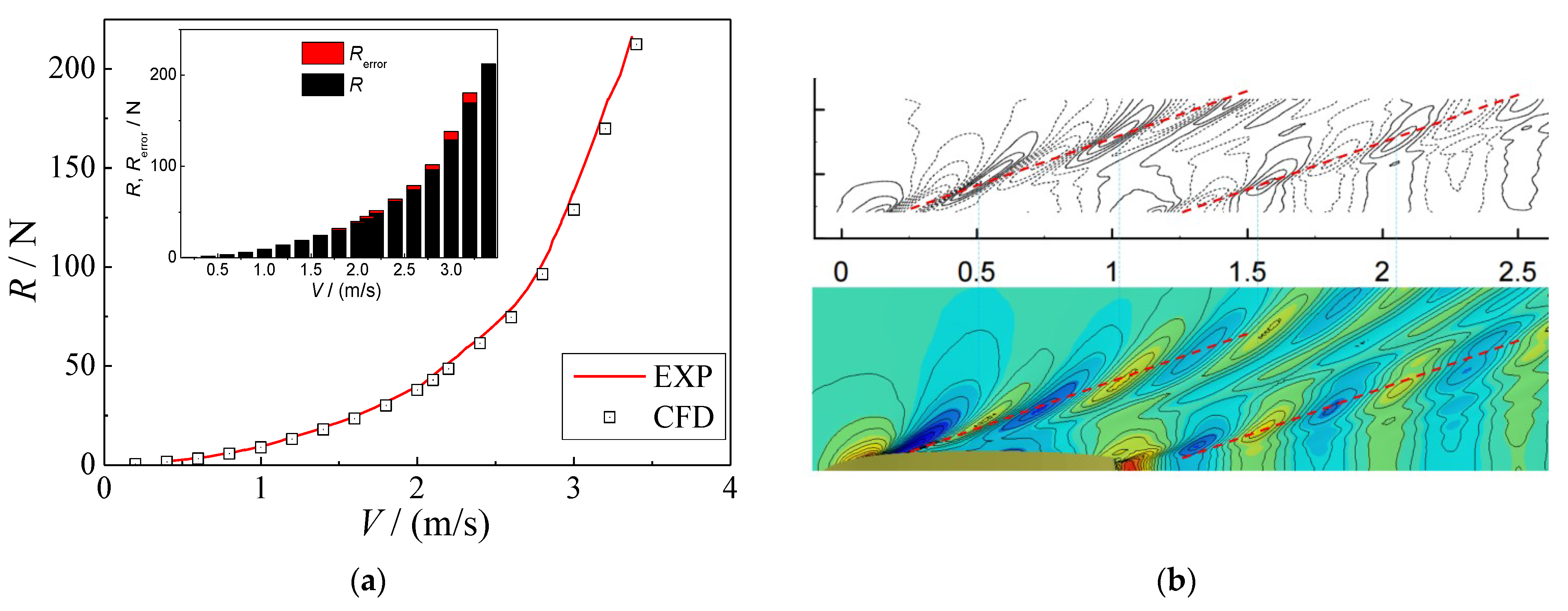
3.3.1. Ship Wave and Resistance
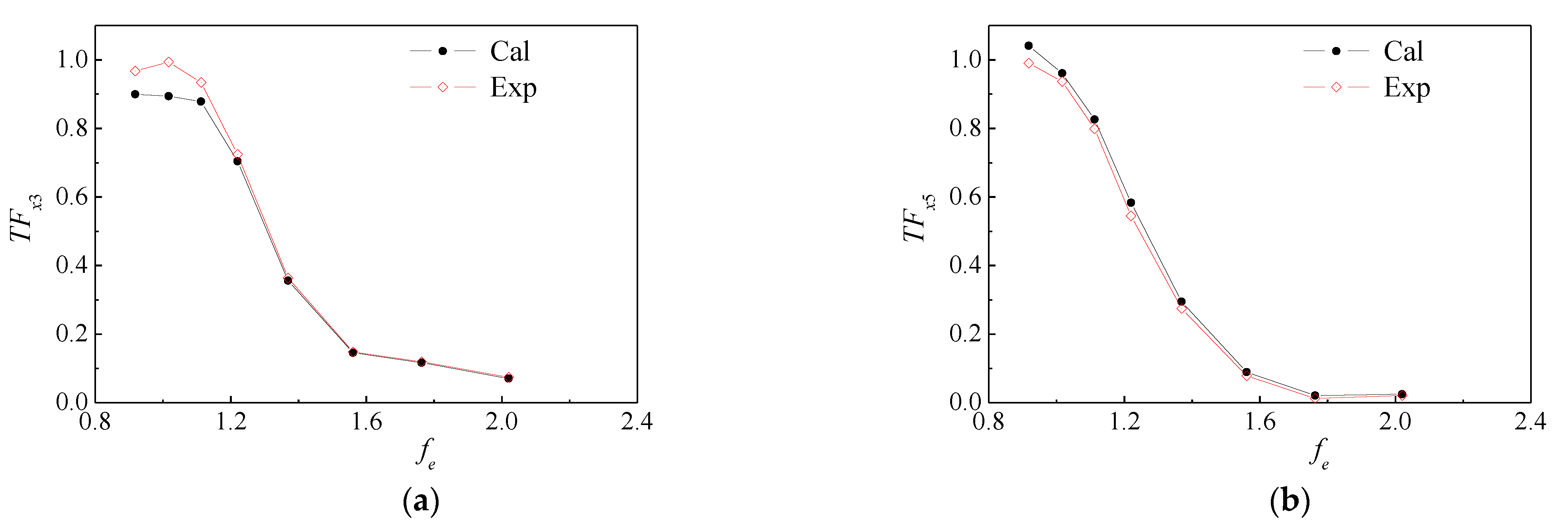
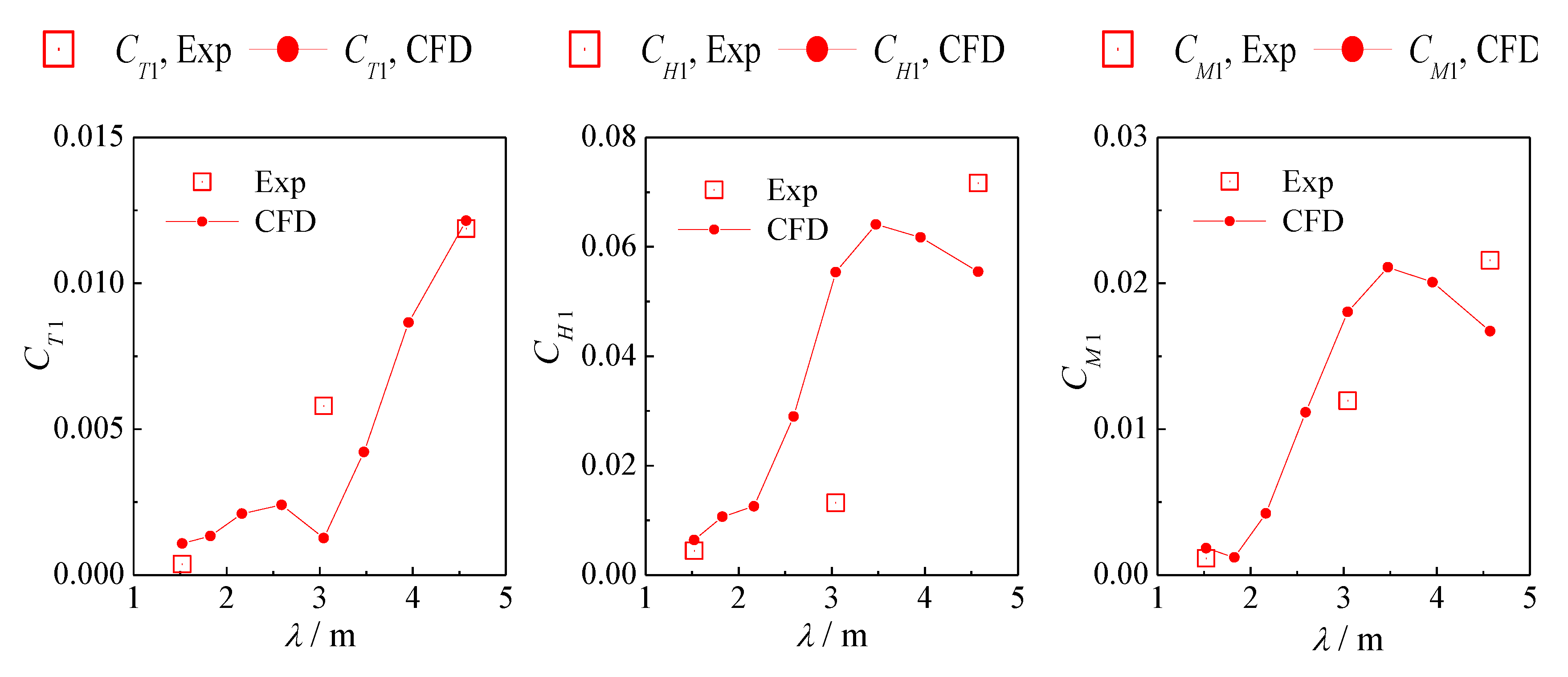
3.3.2. Ship in Head Wave
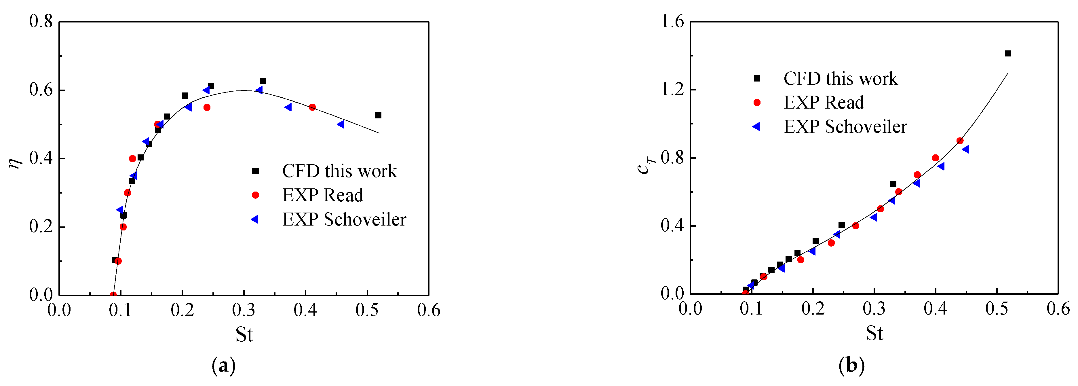
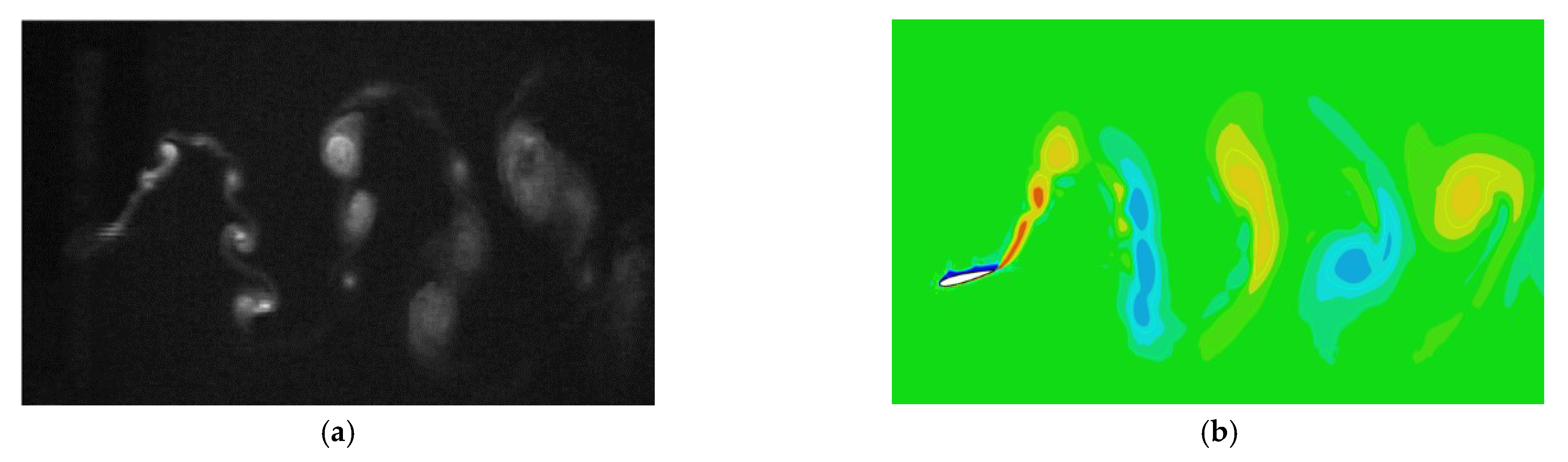
3.3.3. Flapping Foil Performance and Wake Vortex
4. Results and Analysis
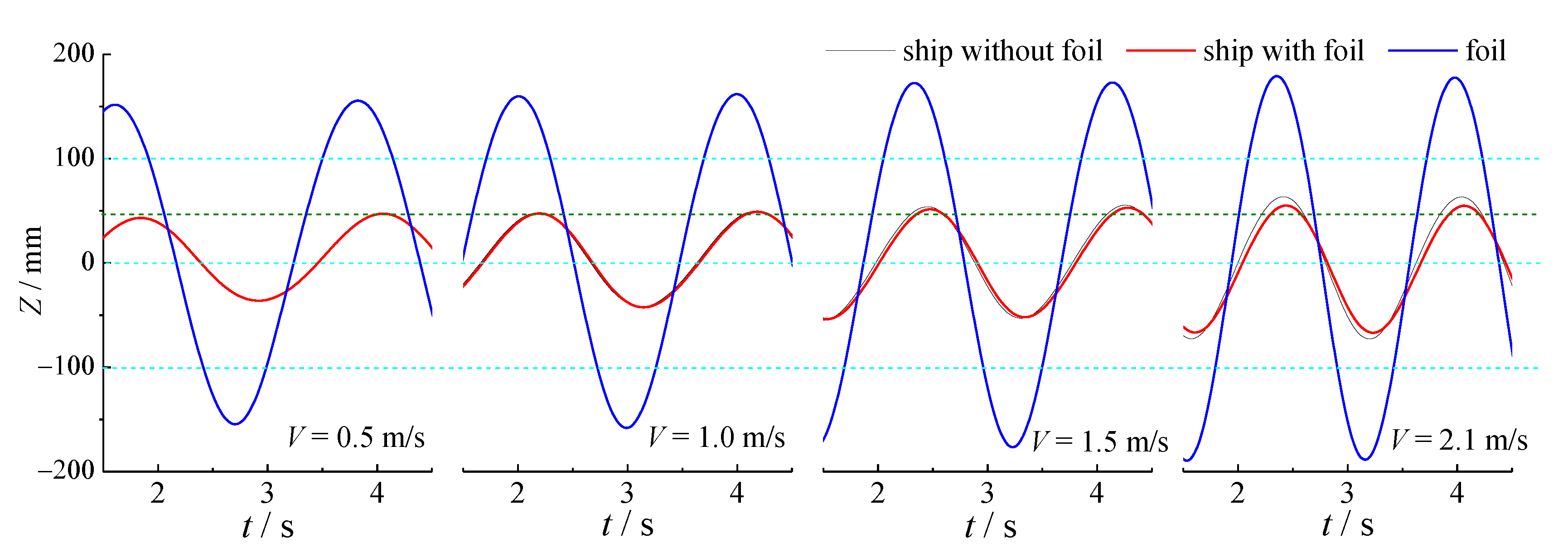
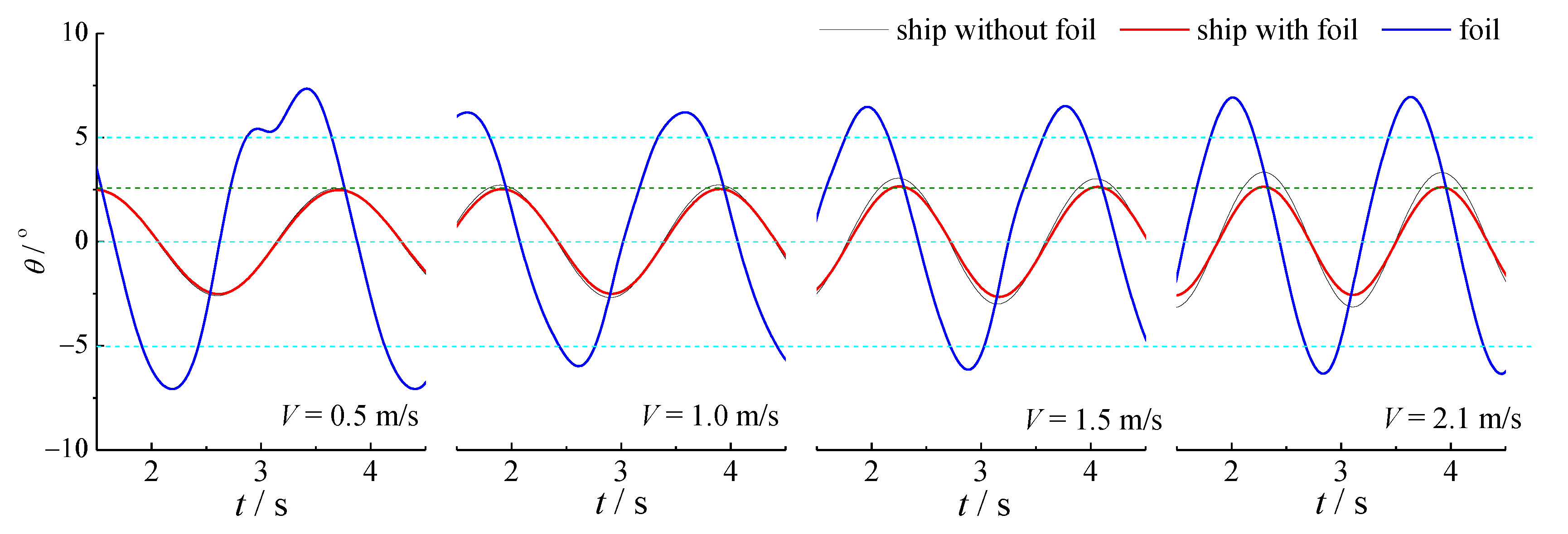
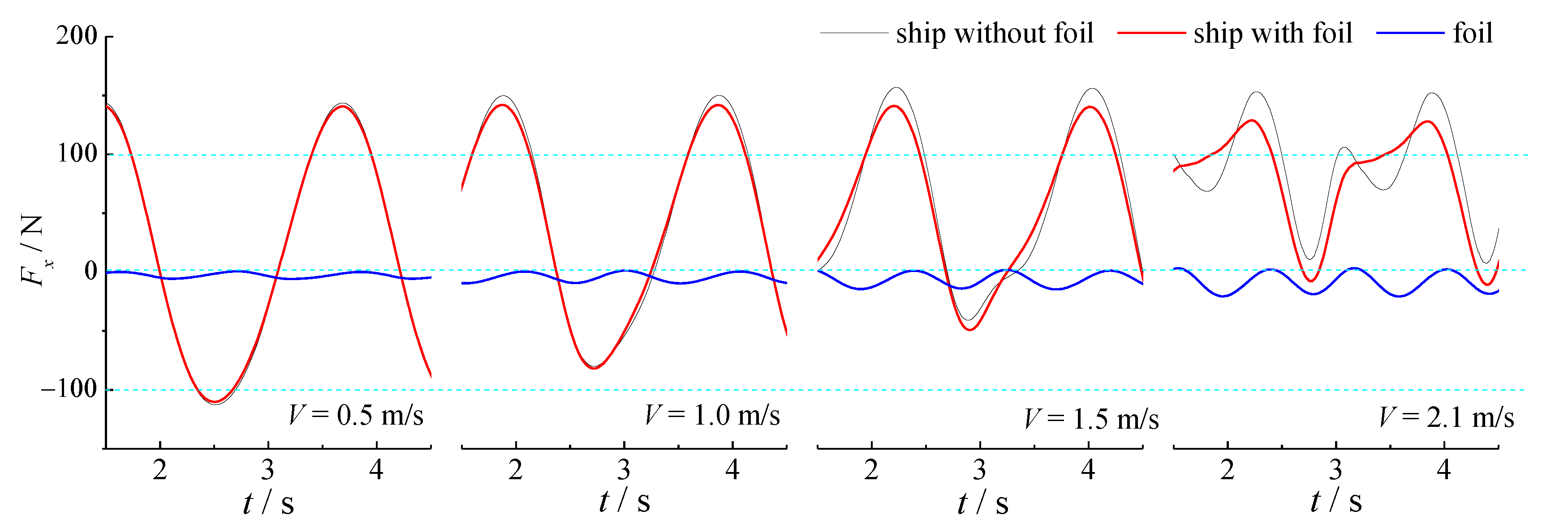
4.1. Co-Simulation Result
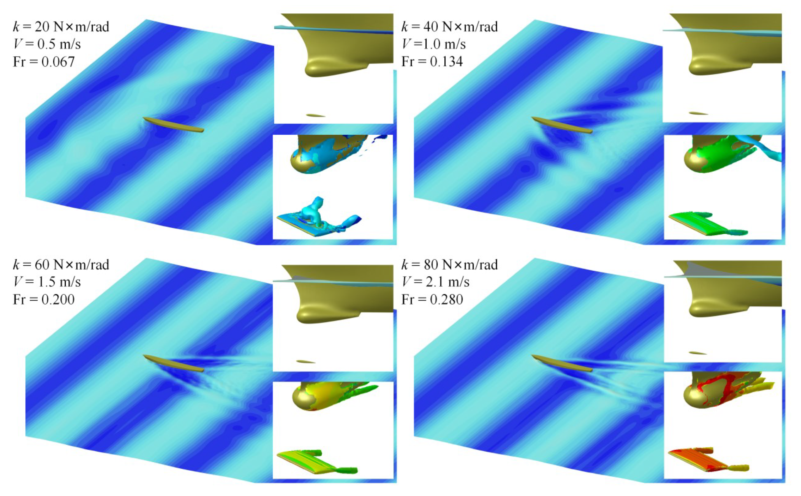
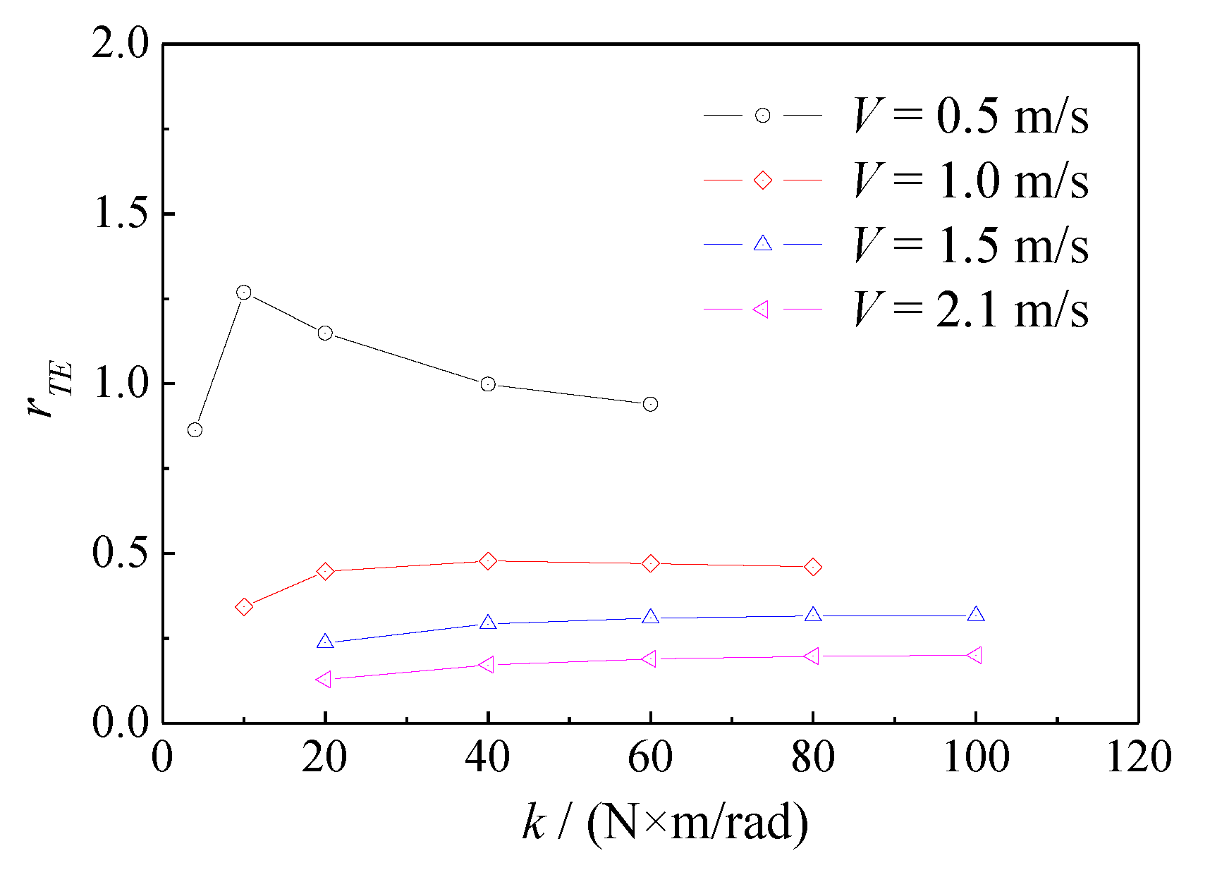
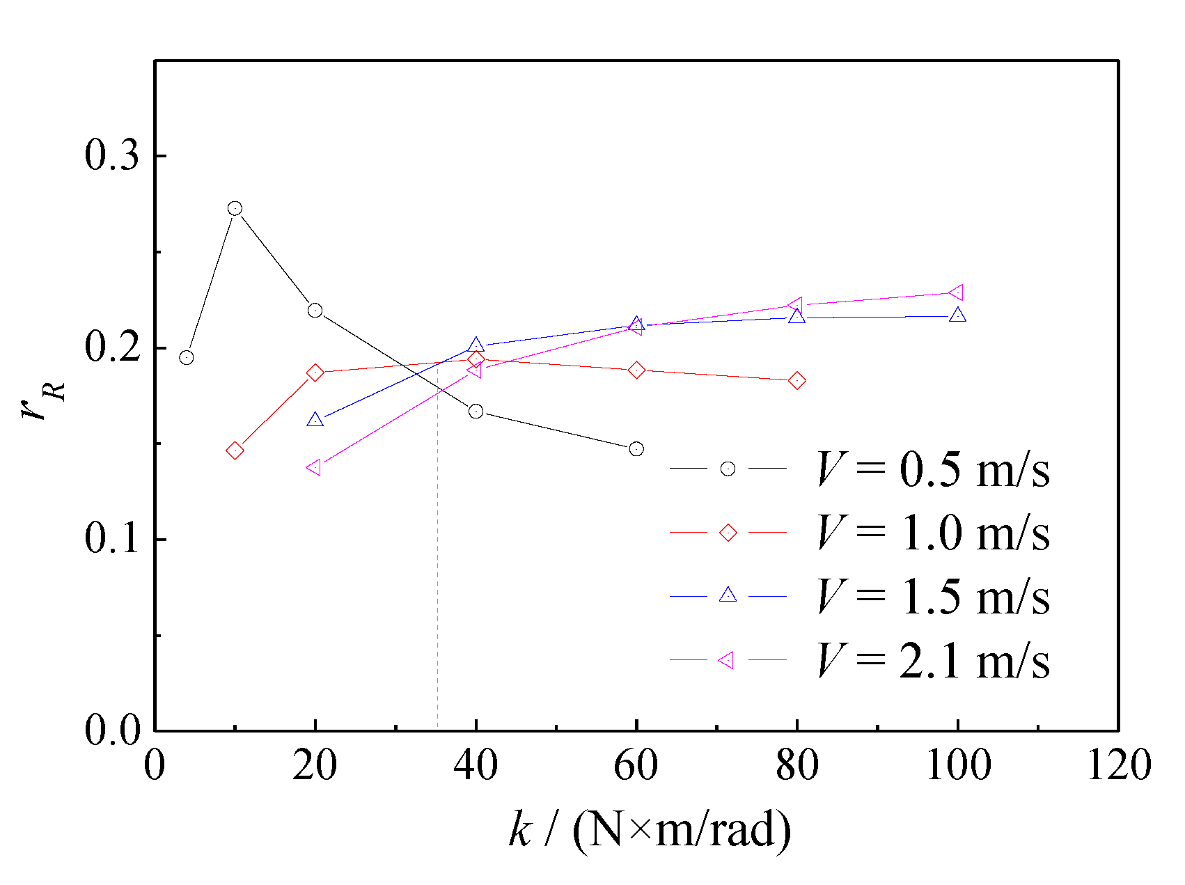
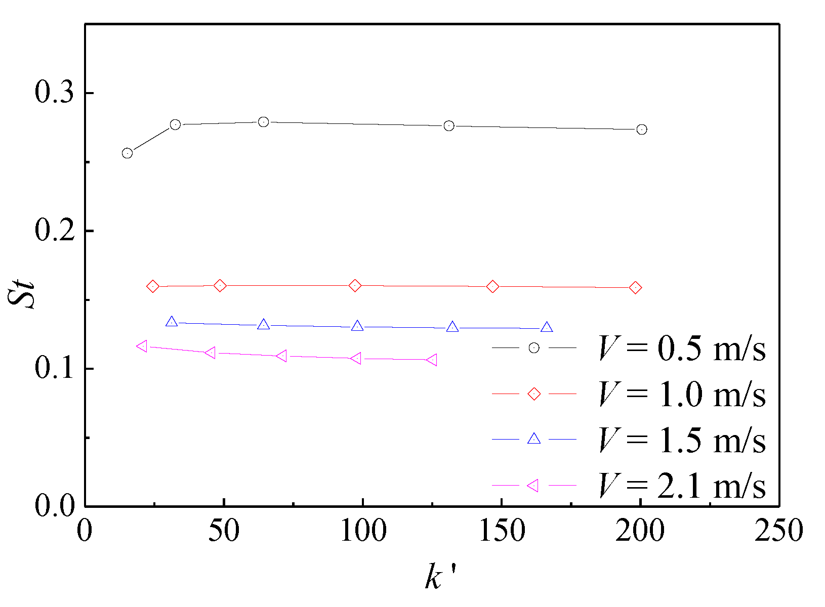
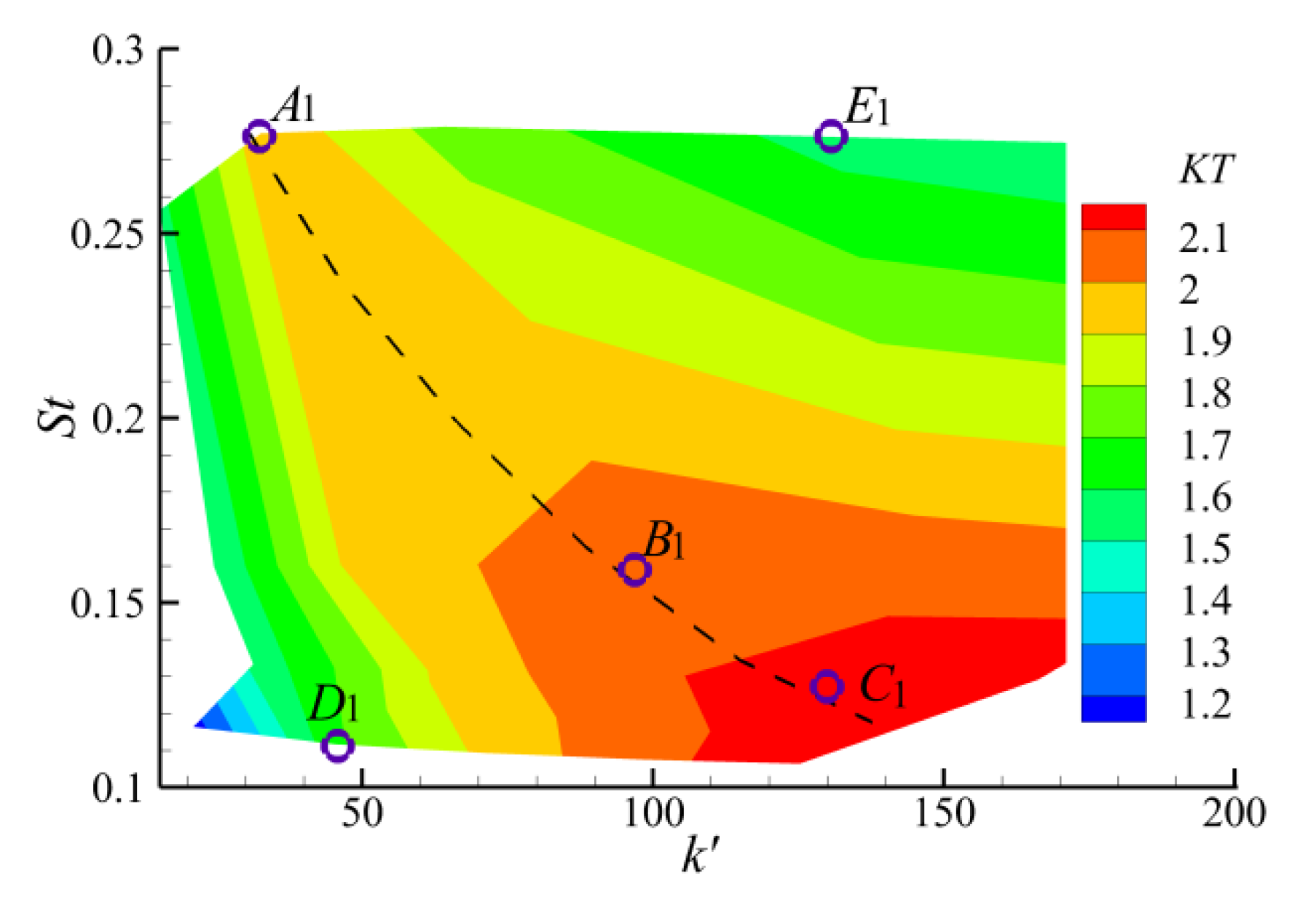
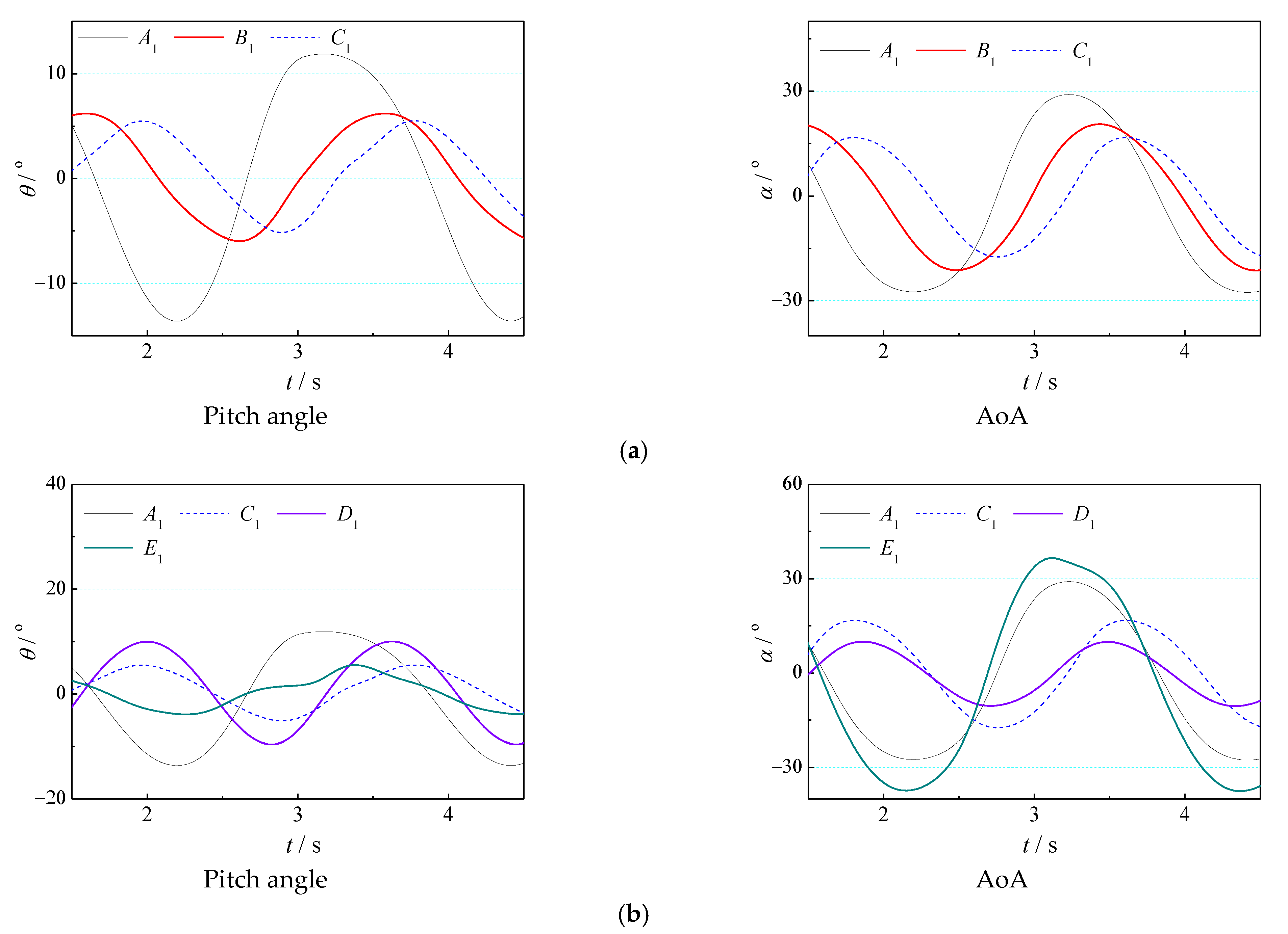
4.2. Effect of Torsion Spring Stiffness
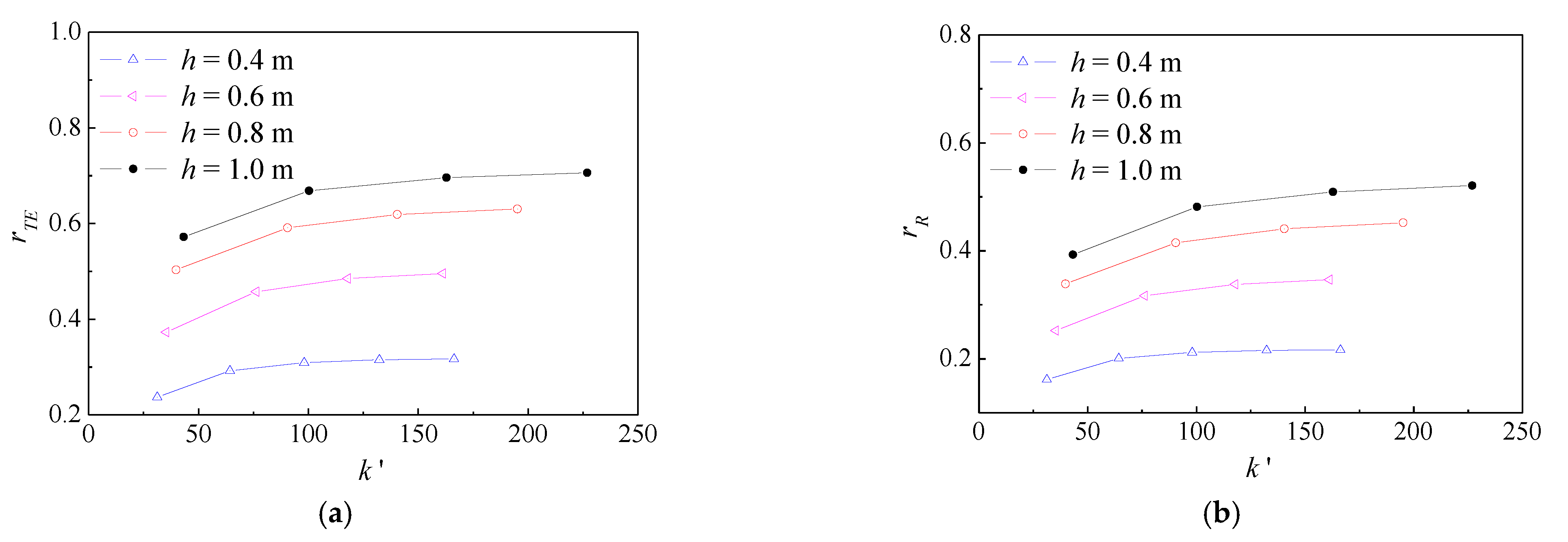
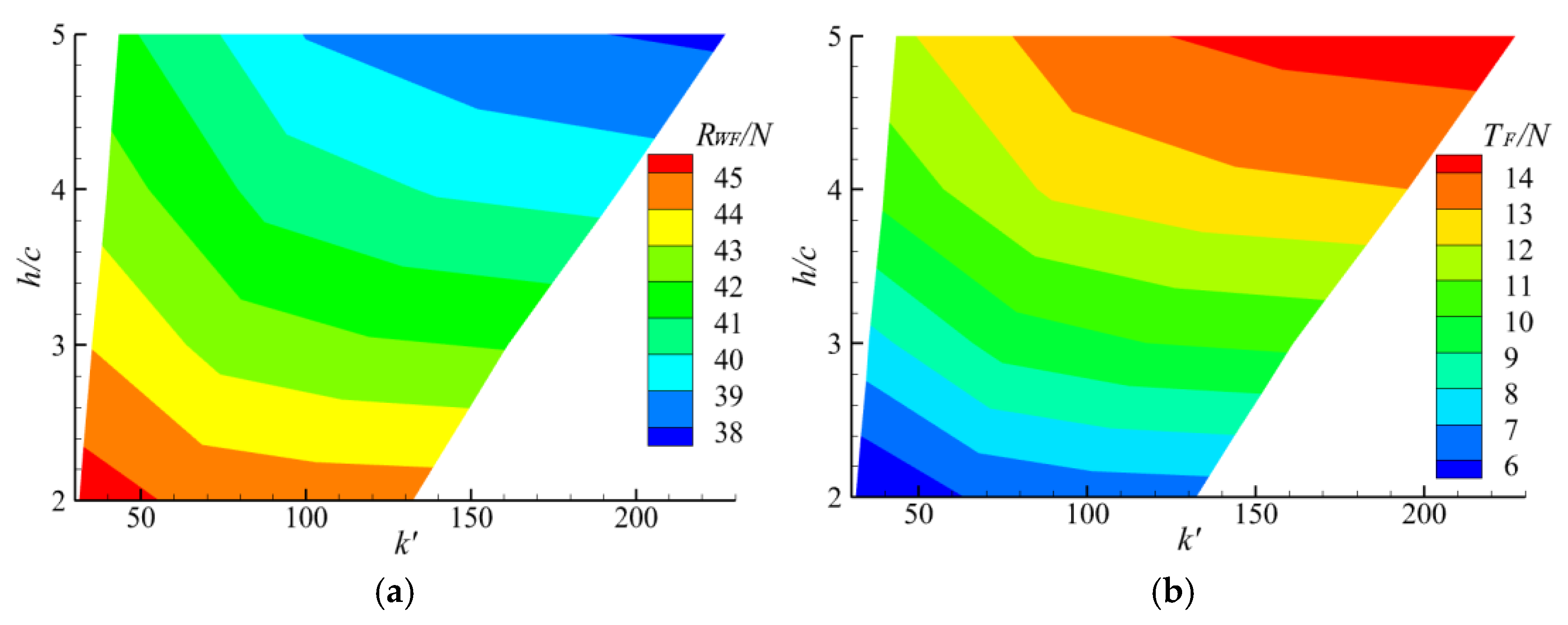
4.3. Damping Effect of the Bow Foil Span
5. Conclusions
- In this paper, the ISIS-CFD solver based on NUMECA software is used to realize joint simulation of a ship with semi-active elastic flapping foil in head waves. The complex interaction between the hull, flapping foil, and waves is considered, which enriches the analysis methods of such problems;
- In numerical simulation, the increasing thrust and reducing drag effect of the elastic flapping foil to the ship in waves is preliminarily realized. In the range of bow foil span and spring stiffness discussed in this paper, the thrust enhancement ratio is roughly in the range of 24–71%, while the drag reduction rate is roughly in the range of 16–52%. Under the working condition of (Fr = 2.0), the resistance reduction ratio exceeds 50%, which represents significant energy saving in head seas with use of the bow foil.
- This paper discusses the influence of key design parameters on the thrust-increasing and drag reducing capability of a semi-active bow foil system, including spring stiffness and flapping foil span. It can be roughly determined that there can be an optimal range of spring stiffness so that the hull with bow foil system can have the effect of increasing thrust and reducing drag in a large range of speed. The longer the span of the flapping foil is, the better the effect of thrust increase and drag reduction to the hull is. However, the thrust increase ratio and drag reduction rate of the system become more and more gentle with an increase in span length.
Author Contributions
Funding
Institutional Review Board Statement
Informed Consent Statement
Data Availability Statement
Conflicts of Interest
References
- Hu, L.; Wu, H.; Yuan, Z.; Li, W.; Wang, X. Roll motion response analysis of damaged ships in beam waves. Ocean Eng. 2021, 2, 108558. [Google Scholar] [CrossRef]
- Belibassakis, K.; Bleuanus, S.; Vermeiden, J.; Townsend, N. Combined performance of innovative biomimetic ship propulsion system in waves with Dual Fuel ship engine and application to short-sea shipping. In Proceedings of the 31st International Ocean and Polar Engineering Conference, Rhodes, Greece, 20–25 June 2021. [Google Scholar]
- Lee, J.H.; Kim, Y.; Kim, B.S.; Gerhardt, F. Comparative study on analysis methods for added resistance of four ships in head and oblique waves. Ocean Eng. 2021, 236, 109552. [Google Scholar] [CrossRef]
- Bessho, M.; Kyozuka, Y.; Miyazaki, M. On the Ship Motion Reduction by Anti-Pitching Fins in Head Seas. J. Soc. Nav. Archit. Jpn. 1983, 153, 176–187. [Google Scholar] [CrossRef] [Green Version]
- Wu, T.N.; Guo, J.; Chen, Y.N.; Chen, W.C. Experimental study of ship pitching motion reduction using anti-pitching fins. In Proceedings of the JFPS International Symposium on Fluid Power; The Japan Fluid Power System Society: Tokyo, Japan, 1996; Volume 3, pp. 223–228. [Google Scholar] [CrossRef]
- Sclavounos, P.D.; Borgen, H. Seakeeping Analysis of a High-Speed Monohull With a Motion-Control Bow Hydrofoil. J. Ship Res. 2004, 48, 77–117. [Google Scholar] [CrossRef]
- Wu, T. Extraction of flow energy by a wing oscillating in waves. J. Ship Res. 1972, 16, 66–78. [Google Scholar] [CrossRef]
- Isshiki, H. A Theory of Wave Devouring Propulsion (1st Report). J. Soc. Nav. Archit. Jpn. 1982, 151, 54–64. [Google Scholar] [CrossRef]
- Isshiki, H.; Murakami, M. A Theory of Wave Devouring Propulsion (4th Report). J. Soc. Nav. Archit. Jpn. 1984, 156, 102–114. [Google Scholar] [CrossRef]
- Isshiki, H.; Murakami, M.; Terao, Y. Thrust Generation by a Hydrofoil Driven by Waves-A Basic Aspect of Wave Devouring Propulsion; Springer: Berlin/Heidelberg, Germany, 1986. [Google Scholar]
- Grue, J.; Mo, A.; Palm, E. Propulsion of a foil moving in water waves. J. Fluid Mech. 1988, 186, 393–417. [Google Scholar] [CrossRef]
- Jakobsen, E. The foil propeller, wave power for propulsion. In 2nd International Symposium on Wave and Tidal Energy; BHRA Fluid Engineering: Cranfield, UK, 1981; pp. 363–369. [Google Scholar]
- Naito, S.; Isshiki, H.; Fujimoto, K. Thrust generation of a fin attached to a ship in waves. J. Kansai Soc. Nav. Archit. 1986, 202, 23–29. [Google Scholar]
- Zhang, Y.P.; Xu, L. A propulsion unit for ships based on water-treading of flapping foils. Ocean Eng. 2021, 235, 109330. [Google Scholar] [CrossRef]
- Zhang, Y.P.; Xu, L.; Zhou, Y. A wave foil with passive angle of attack adjustment for wave energy extraction for ships. Ocean Eng. 2022, 246, 110627. [Google Scholar] [CrossRef]
- Rozhdestvensky, K.V.; Htet, Z.M. A mathematical model of a ship with wings propelled by waves. J. Mar. Sci. Appl. 2021, 20, 595–620. [Google Scholar] [CrossRef]
- Bøckmann, E.; Steen, S. Model test and simulation of a ship with wavefoils. Appl. Ocean Res. 2016, 57, 8–18. [Google Scholar] [CrossRef]
- Linden, H. Improved Combination with Floating Bodies, of Fins Adapted to Effect Their Propulsion. GB Patent GBD189514630, 18 July 1896. [Google Scholar]
- Rozhdestvensky, K.V.; Ryzhov, V.A. Aerohydrodynamics of flapping-wing propulsors. Prog. Aerosp. Sci. 2003, 39, 585–633. [Google Scholar] [CrossRef]
- Naito, S.; Isshiki, H. Effect of bow wings on ship propulsion and motions. Appl. Mech. Rev. 2005, 58, 253–268. [Google Scholar] [CrossRef]
- Terao, Y. Wave devouring propulsion system—From concept to trans-pacific voyage. In Proceedings of the International Conference on Offshore Mechanics and Arctic Engineering—OMAE. American Society of Mechanical Engineers Digital Collection, Honolulu, HI, USA, 31 May–5 June 2009; pp. 119–126. [Google Scholar]
- Terao, Y.; Sakagami, N. Design and development of an autonomous wave-powered boat with a wave devouring propulsion system. Adv. Robot. 2015, 29, 89–102. [Google Scholar] [CrossRef]
- Bøckmann, E.; Steen, S. Experiments with actively pitch-controlled and spring-loaded oscillating foils. Appl. Ocean Res. 2014, 48, 227–235. [Google Scholar] [CrossRef]
- Bowker, J.A.; Tan, M.; Townsend, N.C. Forward speed prediction of a free-running wave-propelled boat. IEEE J. Ocean. Eng. 2020, 46, 402–413. [Google Scholar] [CrossRef]
- Bowker, J.A.; Townsend, N.C. Evaluation of bow foils on ship delivered power in waves using model tests. Appl. Ocean Res. 2022, 123, 103148. [Google Scholar] [CrossRef]
- De Silva, L.W.A.; Yamaguchi, H. Numerical study on active wave devouring propulsion. J. Mar. Sci. Technol. 2012, 17, 261–275. [Google Scholar] [CrossRef] [Green Version]
- Politis, G.K.; Politis, K. Biomimetic propulsion under random heaving conditions, using active pitch control. J. Fluid Struct. 2014, 47, 139–149. [Google Scholar] [CrossRef]
- Belibassakis, K.; Politis, G. Hydrodynamic performance of flapping wings for augmenting ship propulsion in waves. Ocean Eng. 2013, 72, 227–240. [Google Scholar] [CrossRef]
- Belibassakis, K.; Filippas, E. Ship propulsion in waves by actively controlled flapping foils. Appl. Ocean Res. 2015, 52, 1–11. [Google Scholar] [CrossRef]
- Filippas, E.S. Augmenting Ship Propulsion in Waves Using Flapping Foils Initially Designed for Roll Stabilization. Procedia Comput. Sci. 2015, 66, 103–111. [Google Scholar] [CrossRef] [Green Version]
- Huang, S.W.; Wu, T.L.; Hsu, Y.T.; Guo, J.H.; Tsai, J.F.; Chiu, F.C. Effective energy-saving device of eco-ship by using wave propulsion. In Proceedings of the 2016 Techno-Ocean (Techno-Ocean), Kobe, Japan, 6–8 October 2016. [Google Scholar]
- Filippas, E.S.; Belibassakis, K.A. A nonlinear time-domain BEM for the performance of 3D flapping-wing thrusters in directional waves. Ocean Eng. 2022, 245, 110157. [Google Scholar] [CrossRef]
- Belibassakis, K.; Filippas, E.; Papadakis, G. Numerical and Experimental Investigation of the Performance of Dynamic Wing for Augmenting Ship Propulsion in Head and Quartering Seas. J. Mar. Sci. Eng. 2022, 10, 24. [Google Scholar] [CrossRef]
- Feng, P.; Ma, N.; Gu, X. A practical method for predicting the propulsive performance of energy efficient ship with wave devouring hydrofoils at actual seas. Proc. Inst. Mech. Eng. Part M J. Eng. Marit. Environ. 2014, 228, 348–361. [Google Scholar] [CrossRef]
- Bøckmann, E.; Yrke, A.; Steen, S. Fuel savings for a general cargo ship employing retractable bow foils. Appl. Ocean Res. 2018, 76, 1–10. [Google Scholar] [CrossRef] [Green Version]
- Filippas, E.S.; Belibassakis, K.A. Hydrodynamic analysis of flapping-foil thrusters operating beneath the free surface and in waves. Eng. Anal. Bound. Elem. 2014, 41, 47–59. [Google Scholar] [CrossRef]
- Politis, G.K. A BEM code for the calculation of flow around systems of independently moving bodies including free shear layer dynamics. In Proceedings of the Advances Boundary Elemen Techniques X, WIT Conference, Athens, Greece, 9–11 July 2008. [Google Scholar]
- Wilson, R.V.; Stern, F.; Coleman, H.W.; Paterson, E.G. Comprehensive Approach to Verification and Validation of CFD Simulations part 2: Application for Rans Simulation of a Cargo/Container Ship. J. Fluids Eng. 2001, 123, 803–810. [Google Scholar] [CrossRef]
- Simone, M.; Ermina, B.; Day, A.H.; Atilla, I. Verification and validation of numerical modelling of dtmb 5415 roll decay. Ocean Eng. 2018; 162, 209–223. [Google Scholar]
- Bhushan, S.; Yoon, H.; Stern, F. Detached eddy simulations and tomographic piv measurements of flows over surface combatant 5415 at straight-ahead and static drift conditions. Ocean Eng. 2021, 238, 109658. [Google Scholar] [CrossRef]
- Anderson, J.M.; Streitlien, K.; Barrett, D.S.; Triantafyllou, M.S. Oscillating foils of high propulsive efficiency. J. Fluid Mech. 1998, 360, 41–72. [Google Scholar] [CrossRef] [Green Version]
- Read, D.A.; Hover, F.S.; Triantafyllou, M.S. Forces on oscillating foils for propulsion and maneuvering. J. Fluid Struct. 2003, 17, 163–183. [Google Scholar] [CrossRef]
- Schouveiler, L.; Hover, F.S.; Triantafyllou, M.S. Performance of flapping foil propulsion. J. Fluid Struct. 2005, 20, 949–959. [Google Scholar] [CrossRef]
- Thaweewat, N.; Phoemsapthawee, S.; Juntasaro, V. Semi-active flapping foil for marine propulsion. Ocean Eng. 2018, 147, 556–564. [Google Scholar] [CrossRef]
- Mei, L.; Yan, W.; Zhou, J.; Yu, D.; Wu, P. Working characteristics of self-pitching flapping foil propulsor. In the 9th Conference on Computational Methods in Marine Engineering; Marine: 2021; Edinburgh. [CrossRef]
- Mei, L.; Zhou, J.; Dong, Y.; Shi, W.; Pan, X.; Li, M. Parametric Analysis for Underwater Flapping Foil Propulsor. Water 2021, 13, 2103. [Google Scholar] [CrossRef]
- Zhou, J.; Yan, W.; Mei, L.; Cong, L.; Shi, W. Principal Parameters Analysis of the Double-Elastic-Constrained Flapping Hydrofoil for Tidal Current Energy Extraction. J. Mar. Sci. Eng. 2022, 10, 855. [Google Scholar] [CrossRef]
- Duvigneau, R.; Visonneau, M. On the role played by turbulence closures in hull shape optimization at model and full scale. J Mar. Sci. Technol. 2003, 8, 11–25. [Google Scholar] [CrossRef]
- Queutey, P.; Visonneau, M. An interface capturing method for free-surface hydrodynamic flows. Comput. Fluids 2007, 36, 1481. [Google Scholar] [CrossRef]
- Rhie, C.M. Numerical study of the turbulent flow past an isolated airfoil with trailing edge separation. AIAA J. 1983, 21, 1525–1532. [Google Scholar] [CrossRef]
- Jasak, H. Error Analysis and Estimation for the Finite Volume Method with Applications to Fluid Flows. Ph.D. Thesis, University of London, London, UK, 1996. [Google Scholar]
- Muzaferija, S.; Peric, M. Computation of free surface flows using interface-tracking and interface-capturing methods. In Nonlinear Water Wave Interaction; Mahrenholtz, O., Markiewicz, M., Eds.; WIT Press: Southampton, UK, 1981; pp. 59–100. [Google Scholar]
- Olivieri, A.; Pistani, F.; Avanzini, A.; Stern, F.; Penna, R. Towing Tank Experiments of Resistance, Sinkage and Trim, Boundary Layer, Wake, and Free Surface Flow Around a Naval Combatant Insean 2340 Model; College of Engineering: Iowa City, IA, USA, 2001; p. 42. [Google Scholar]
- Irvine, M. Pitch and Heave Tests and Uncertainty Assessment for a Surface Combatant in Regular Head Waves. J. Ship. Res. 2008, 52, 146–163. [Google Scholar] [CrossRef]
- Gui, L.; Longo, J.; Metcalf, B.; Shao, J.; Stern, F. Forces, moment, and wave pattern for surface combatant in regular head wavesPart I. Measurement systems and uncertainty assessment. Exp. Fluids. 2001, 31, 674–680. [Google Scholar] [CrossRef]
- Wang, Z.D.; Lao, Y.J.; Li, L.J.; Cong, W.C. Experiment on the characteristics of 3-d vortex ring behind a flexible oscillating caudal fin. J. Hydrodyn. 2010, 22, 393–401. [Google Scholar] [CrossRef]
- Buchholz, J.H.J.; Smits, A.J. On the evolution of the wake structure produced by a low-aspect-ratio pitching panel. J. Fluid Mech. 2006, 564, 433–443. [Google Scholar] [CrossRef] [PubMed] [Green Version]
- Terao, Y.; Isshiki, H. Wave devouring propulsion sea trial. In Eighteenth Symposium on Naval Hydrodynamics; Seaworthiness: Washington, DC, USA, 1991; pp. 296–297. [Google Scholar]
- Triantafyllou, G.S.; Gopalkrishnan, R. Wake mechanics for thrust generation in oscillating foils. Phys. Fluids 1991, 3, 2835–2837. [Google Scholar] [CrossRef]


| Particulars | Value | Unit | |
|---|---|---|---|
| Length at water level | 5.72 | m | |
| Breadth Overall | 0.76 | m | |
| Draft | 0.248 | m | |
| Volume | 0.549 | m3 | |
| Wetted surface | 4.786 | m2 | |
| Airfoil Chord | 0.2 | m | |
| Airfoil Span | 0.4 | m | |
| Wave amplitude | A | 0.05 | m |
| Wave period | T | 2.5 | s |
| Wave length | 9.75 | m | |
| Wave height | H | 0.1 | m |
| Encounter angle of wave | 180 | ◦ |
| Direction | Hull Surface Region | Hydrofoil Surface Region | Parallel Wave Region | Ship Wave Region |
|---|---|---|---|---|
| X | λ/640 | c/128 | λ/80 | λ/160 |
| Y | λ/640 | c/32 | λ/20 | λ/160 |
| Z | λ/640 | c/128 | H/20 | H/20 |
| λ (m) | 1.52 | 1.83 | 2.16 | 2.59 | 3.04 | 3.47 | 3.95 | 4.57 |
| A (mm) | 10.5 | 13.5 | 16.6 | 20.6 | 24.7 | 28 | 31.1 | 33.8 |
| fe (Hz) | 2.02 | 1.763 | 1.561 | 1.369 | 1.22 | 1.112 | 1.017 | 0.918 |
| Ship Model Speed V (m/s) | Froude Number | Torsion Spring Stiffness k (N × m/Rad) | Airfoil Span h (m) |
|---|---|---|---|
| 0.5 | 0.067 | 4; 10; 20; 40; 60 | 0.4 |
| 1.0 | 0.134 | 10; 20; 40; 60; 80 | 0.4 |
| 1.5 | 0.200 | 20; 40; 60; 80; 100 | 0.4; 0.6; 0.8; 1.0 |
| 2.1 | 0.280 | 20; 40; 60; 80; 100 | 0.4 |
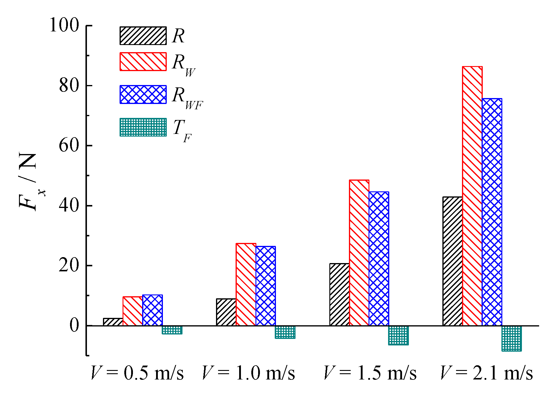
| Hydrodynamic Force (N) | Working Condition | Ship Type | Definition |
|---|---|---|---|
| R | calm water | Ship without foil | axial force acting on hull in calm water |
| RW | in head wave | Ship without foil | axial force acting on hull in waves |
| RWF | in head wave | Ship with bow foil | axial force acting on hull in waves |
| TF | in head wave | Ship with bow foil | axial force acting on bow foil in waves |
Disclaimer/Publisher’s Note: The statements, opinions and data contained in all publications are solely those of the individual author(s) and contributor(s) and not of MDPI and/or the editor(s). MDPI and/or the editor(s) disclaim responsibility for any injury to people or property resulting from any ideas, methods, instructions or products referred to in the content. |
© 2023 by the authors. Licensee MDPI, Basel, Switzerland. This article is an open access article distributed under the terms and conditions of the Creative Commons Attribution (CC BY) license (https://creativecommons.org/licenses/by/4.0/).
Share and Cite
Mei, L.; Yan, W.; Zhou, J.; Shi, W. Thrust Enhancement of DTMB 5415 with Elastic Flapping Foil in Regular Head Waves. J. Mar. Sci. Eng. 2023, 11, 632. https://doi.org/10.3390/jmse11030632
Mei L, Yan W, Zhou J, Shi W. Thrust Enhancement of DTMB 5415 with Elastic Flapping Foil in Regular Head Waves. Journal of Marine Science and Engineering. 2023; 11(3):632. https://doi.org/10.3390/jmse11030632
Chicago/Turabian StyleMei, Lei, Wenhui Yan, Junwei Zhou, and Weichao Shi. 2023. "Thrust Enhancement of DTMB 5415 with Elastic Flapping Foil in Regular Head Waves" Journal of Marine Science and Engineering 11, no. 3: 632. https://doi.org/10.3390/jmse11030632