Article

Non-Hydrostatic Numerical Model of Bragg Resonance on Periodically Submerged Breakwater

by
Tolulope Emmanuel Oginni
1,2,* and
Xizeng Zhao
1,3,4
1
Ocean College, Zhejiang University, Zhoushan 316021, China
2
School of Geography, Environment and Earth Science, Victoria University of Wellington, Wellington 6140, New Zealand
3
School of Marine Engineering Equipment, Zhejiang Ocean University, Zhoushan 316022, China
4
Guangdong Advanced Energy Laboratory (YANGJIANG Offshore Wind Lab), Guangzhou 510530, China
*
Author to whom correspondence should be addressed.
J. Mar. Sci. Eng. 2023, 11(3), 650; https://doi.org/10.3390/jmse11030650
Submission received: 2 March 2023 / Revised: 15 March 2023 / Accepted: 17 March 2023 / Published: 20 March 2023
(This article belongs to the Special Issue Wave Interactions with Coastal Structures II)

Abstract

:
The Bragg resonance (BR) of a reflection coefficient resulting from the propagation of monochronic waves over periodically submerged breakwater was studied using the non-hydrostatic numerical model SWASH (Simulating WAves till SHore). Bragg resonance occurs when the incident wavelength is approximately twice the structural length of a periodic structural breakwater according to Bragg’s law and conditions. This study aimed to investigate the dynamics of Bragg resonance at water depths of 0.2, 0.3, and 0.4 m as the number of periodically submerged breakwater and their wavelengths changed. Specifically, this study focused on the Bragg resonance point of occurrence at a ratio of two structural wavelengths to the incoming wavelengths (2S/L). Regular waves were propagated over two periodically submerged breakwaters, with increasing structural wavelengths from 1 to 2 m at 0.2 m intervals. The results showed that Bragg resonances rapidly increase in value as the water depth decreases, but do not shift in their point of occurrence as the number of periodically submerged breakwaters increases. However, the Bragg resonance shifts leftward in 2 S / L as the structural wavelength increases, with a slight increase in value at shallower water depths. More incident wave energy is reflected when the number of periodically submerged breakwater increases compared with when the structural wavelength of the periodically submerged breakwater increases. The differences in the Bragg resonance values are associated with the changes in the number of periodically submerged breakwater. Additionally, the shift in the point of occurrence was influenced by both water depth and structural length. This causes the Resulted Bragg resonance to deviate from the Expected Bragg resonance, which could be the reason why Bragg resonance does not mainly occur at 2 S / L = 1 , as stated by Bragg’s law.

1. Introduction

The propagation of regular surface waves over an undulating seabed topography results in different waveforms. The reflection of waves by the undulating seabed can provide coastal engineers with a mechanism to protect the coastal area from wave attack by introducing an artificial sandbar such as periodically submerged breakwater. The reflected wave should be at its peak when the wavelength of the undulating seabed is approximately twice that of the incident surface wavelength. This phenomenon is known as Bragg resonance (BR). Understanding the phenomenon behind Bragg resonance is important in understanding how new sandbars are formed from erodible beds [1,2,3,4,5], as well as in developing techniques for introducing artificial bars for coastal protection [6,7,8,9,10].
Natural surface wave propagation over undulating seabeds and ripples was previously studied by Davies [11] and further expanded upon both theoretically and experimentally [12]. Based on their studies and observational interest in using different wave properties and submerged structure configurations, Bragg resonance reflection, has previously been defined by different scholars. The reflection from multiple submerged sinusoidal structures could be at its peak if the incident wavelength is approximately twice the structural length, which is known as Bragg resonance. It can be deduced that Zhang et al. [13] ratio of the incident wavelength to the distance between structures for Bragg resonance reflection is 1:2. Additionally, Gao, Ma et al. [14] numerically investigated the effect of Bragg resonance on harbor by propagating a regular long waves over series of sinusoidal bars with different properties; their studies show that periodic bar topographies can effectively mitigate harbor oscillations through Bragg resonant reflection, and the alleviating effect is enhanced as the number or amplitude of bars increases, with an optimal normalized wavelength that is usually less than 1.0 and fluctuates with the amplitude of bars.
Additionally, Bragg’s resonance reflection occurs twice when the bar distance is equal to the wavelength of the incident waves [15]. Jeon and Cho [7] consider the concept of Bragg reflection to occur when the wave number of the incident wave is approximately double that of the corrugated bottom topography. This is the relationship between the wave number of the incident wave and the wave number of the submerged structures. Similarly, Liu, Zeng, and Huang [16] defined Bragg resonance reflection as occurring when the wavelength of surface waves is approximately two times the wavelength of the seabed undulations, which is similar to how Jeon and Cho [7] described it. However, using the term wavelength instead of the wave number is the same, because the relationship between the two properties is 2π.
Furthermore, various model setups have been used to study Bragg resonance reflection through one or a combination of laboratory experiments, numerical simulations, and theoretical analyses. With respect to bar-shaped configurations, a trapezoidal shape-like breakwater is considered more economical than other shapes. However, the rectangular bar shape reflects more waves than the trapezoidal, although the trapezoidal covers less area, making it preferable in practice [17,18]. Cho, Lee, and Kim [17] conducted experimental studies on the strong reflections of permeable and impermeable submerged breakwaters with trapezoidal and rectangular bar configurations. The results show a good relationship between the experimental data and the eigenfunction expansion method for the impermeable breakwater, which has a high peak reflection compared to that of the permeable breakwater; both increase as the number of breakwaters increases.
Zhang et al. [13] compared their numerical simulation data with experimental measurements [17] to demonstrate how Bragg’s resonance reflection on a permeable trapezoidal bar behaves. Their results were closely related, and their conclusion agreed that an increase in the number of breakwaters significantly reflects the generated wave. However, Zhang et al. [13] concluded that this significant impact on wave motion could also be related to the wave period, which is in turn related to the wave number.
Liu, Luo, and Zeng [9] reported that the peak of Bragg resonance reflection depends on the number of bars, relative bar height, and the relative bar width after showing the influence of these three structural parameters on the Bragg resonance. Three closed-form analytical solutions were used for three sets of submerged Bragg breakwaters: triangular, rectified cosinusoidal, and idealized trapezoidal bar-shaped. The curve for the optimal collocation was developed for the three sets of bars, relative bar height, and relative bar width for the three breakwater types. Additionally, it was concluded that for long waves, the peak Bragg resonance reflection does not precisely occur when the wavelength is twice the distance between structures as obtained by Mile’s method (Bragg’s law), but there is a slight positive deviation [16,19].
Additionally, a recent study has shown that the peak values of subharmonic Bragg resonance reflections are not always lower than that of the primary Bragg resonance reflection [16,19]. They also revealed that the downward shift in the peak phase of the Bragg resonance reflection was limited to a few bars and that a further increase in the number of bars did not change the peak phase and values.
Several studies have made similar assumptions and drawn similar conclusions regarding Bragg resonance reflection, albeit using different approaches. Many of Miles, theories which have been a reference point for most theoretical analysis, have shown that Bragg resonance reflection phenomena occur when the wavelength of the propagated wave is twice or approximately twice the distance between adjacent submersible breakwaters [16,19,20,21,22]. The phase and peak magnitude of Bragg resonance reflections are influenced by the breakwater configuration, including the bar number, bar shape, bar height, bar width, and bar spacing. This study’s experimental and numerical simulation approach has shown good agreement with the above findings [7,13,17,23].
Simulating WAves till SHore (SWASH) is a non-hydrostatic numerical model based on the simulation of a non-linear shallow water equation [24]. It reduces the vertical resolution by adequately computing the free surface flow through single-valuing the free surface functions and implementing the fundamental conservation of mass and momentum. Although it has computation efficiency similarities with Boussinesq models, it is less complex in implementation, maintenance, and the improvement of its robustness, making it suitable for numerical studies with limited timing [25].
Previous studies on Bragg resonance have often overlooked the importance of using an incident wave with a specific breakwater configuration that complies with Bragg’s law. This law composed that a regular wave must propagate over a regular wavelike breakwater (sinusoidal) in order to observe Bragg resonance reflection, similar to the experimental study by Heathershaw [26]. However, many studies have deviated from this condition and chosen parameters without considering the fundamental principles of Bragg’s law. In contrast, our study places great emphasis on Bragg’s law and the conditions surrounding the Bragg resonance phenomenon in both wave properties and structural configurations.
In addition to using the correct breakwater configuration, our study also considers a range of constraints and conditions that must be considered when studying Bragg resonance reflection. These include parameters such as 2 π a / L , 2 π b / L , 2 π b / S , a h , b / h , a L 2 / 4 π 2 h 3   1 , as well as the wave parameters (incident wave amplitude a, wavelength L, and water depth h) and structural parameter (structure amplitude b, and structure wavelength S). By carefully controlling these variables, our study aims to provide a more comprehensive understanding of the effects of periodically submerged breakwater numbers and wavelengths on Bragg resonance at different water depths.
This current study is unique from previous studies in that it focuses specifically on Bragg resonance studies and their differences from resonance and reflection coefficient studies. While previous studies have investigated various aspects of wave structure interaction, our study is dedicated to understanding the underlying principles and conditions that govern Bragg resonance reflection. By using a non-hydrostatic numerical model, we are able to simulate and analyze the effects of different breakwater configurations on Bragg resonance, and to make meaningful comparisons with previous studies. Overall, our study provides a valuable contribution to the field of wave structure interaction and Bragg resonance and sheds new light on this fascinating phenomenon.

2. Methodology

Governing Equations and Boundary Conditions

The governing equations guiding the SWASH model are the Navier–Stokes equations under three-dimensional unsteady incompressible and Reynolds average conditions [24]. Non-linear shallow-water and non-hydrostatic pressure equations govern the model. The governing equations for a two-dimensional vertical model under the Cartesian coordinate system o x z can be expressed as
u x + w z = 0
u t + u 2 x + u w z + 1 ρ 0 q x + 1 ρ 0 η x = τ x x x + τ x z z
w t + u w x + w 2 z + 1 ρ 0 q z = τ x z x + τ z z z
where u and w are the flow velocity in the x- and z-directions, respectively, η(x,t) is the free-surface elevation, ρ0 indicates fluid density, t is time, g is the gravity acceleration, q is the non-hydrostatic pressure, and τij represents the horizontal turbulent stresses.
The turbulent stresses may be written as:
τ x x = 2 ν t u x , τ x z = ν t w x , τ z x = ν t u z , τ z z = 2 ν t w z
where v t is the horizontal eddy viscosity.
In this study, d represents the bottom, i.e., vertical depth along x-direction, and according to the impenetrable condition, the boundary condition equation of the bottom and wave surfaces of the model can be expressed as
w | z = η = η t + u d x
w | z = d = u d x
Using the above boundary condition equation and integrating Equation (1) over the water depth h, the final free surface equation is given as follows:
η t + x d η u d z = 0
The pressure boundary condition is written as follows when the surface tension is ignored at the free surface.
q | z = η = 0
SWASH model generates waves on the open boundary of the computational domain by setting the velocity change at the boundary. In order to simulate an incident wave without reflection occurring at the boundary, the weak reflection boundary condition in the SWASH model was written as
u b = ± h g ( 2 η b η )
Assuming that both the incident wave and the outgoing wave are perpendicular to the boundary, this weak reflection boundary condition has proved its efficiency in simulating shallow-water waves. The positive and negative signs depend on the boundary position in the equation and u b is the velocity of the incident wave and η b is the free-surface elevation at the boundary. In addition, SWASH adopts the Sommerfeld radiation boundary condition to absorb the waves at the boundary so that no reflection occurs when the waves pass the boundary. Assuming that the boundary is parallel to the y-axis, the Sommerfeld radiation boundary condition is expressed as
u t + g h u x = 0
At the same time, the radiation condition can be used together with the sponge layer boundary condition, and the sponge layer boundary condition formula is
μ = 1 4 tanh sin ( π ( 4 x ~ 1 ) 2 / 2 ) 1 ( 4 x ~ 1 ) + 1 , 0 < x ~ < 1 2 1 4 tanh sin ( π ( 3 4 x ~ ) 2 / 2 ) 1 ( 3 4 x ~ ) + 1 , 1 2 < x ~ < 1
where x ~ = ( x l 0 ) / l , l represents the length of the sponge layer starting from x = l 0 , and μ is the linear damping coefficient, which needs to be added to the momentum equation of u , and can be expressed as
u t + u 2 x + u w z + 1 ρ 0 p x + 1 ρ 0 η x + μ u = τ x x x + τ x z z

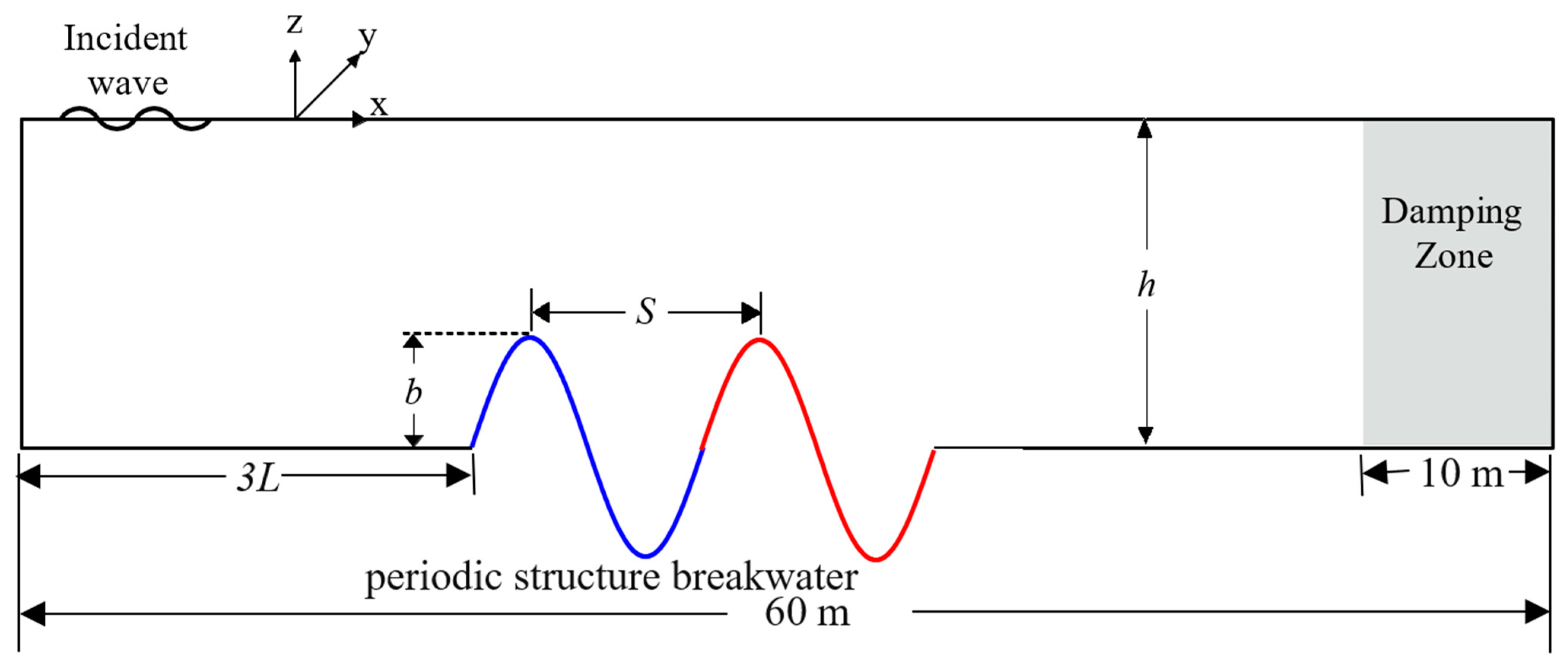
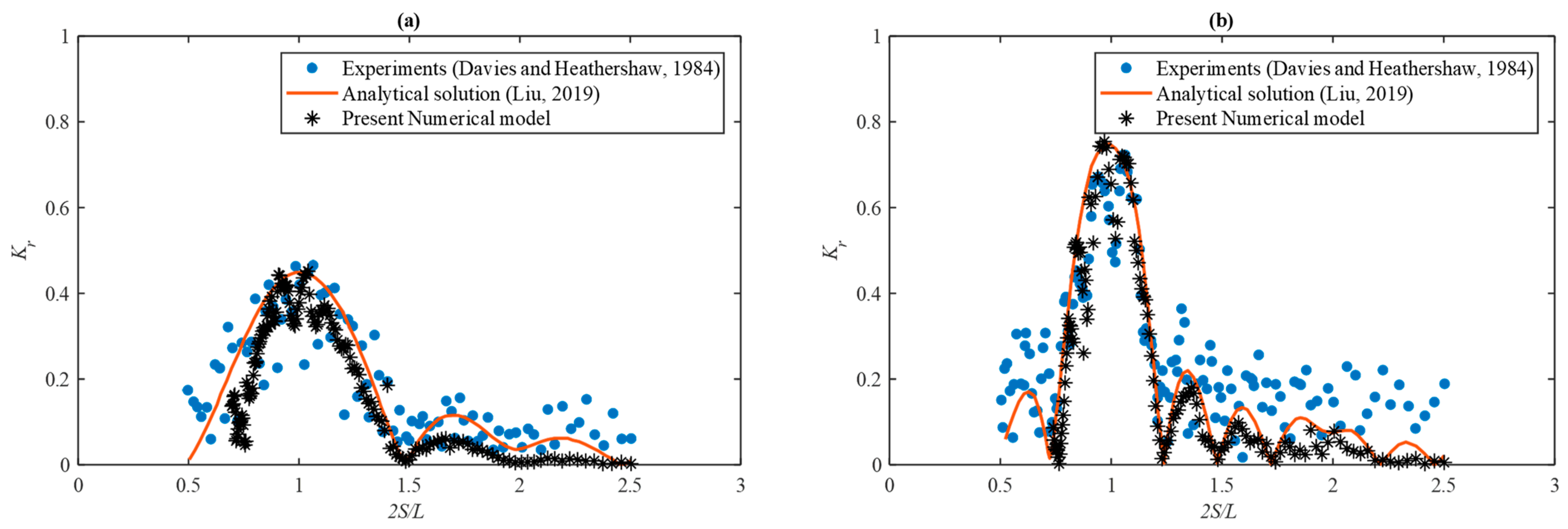
3. Model Setup and Validation

As shown in Figure 1, the figure illustrated the model is designed with a computational wave flume measuring 60 m in length, consisting of a 10 m damping zone and a 50 m working area. The wave propagated through this flume are intermediate regular waves with an amplitude a of 0.02 m, and Table 1 lists the variation in wave parameters used in this study. The number N and the structural wavelength S of the periodically submerged breakwater differ depending on the case study. The Goda and Suzuki [27] methods were used in calculating the reflection coefficient Kr from a two-point reading of the surface wave elevation.
The experiment conducted by Davies and Heathershaw [12] and the analytical solution by Liu, Li, and Lin [3] using the modified mild-slope equation are similar to the cases in the present study using a numerical method, the data from both were used to validate the present numerical model. The experiment was carried out in a 45.72 × 0.91 × 0.91 m wave tank with fixed sinusoidal bars of 0.05 m amplitude b, and 1 m structural wavelength S. Monochromatic sinusoidal waves generated ranges in wave period of 0.7802 T 3.2629 with a time steps of 0.02 s for N = 2 and 0.01 s for N = 4 resulting in 0.2454 k h 1.2271 at 0.156 m water depth h. The results in Figure 2 show good agreement in the present numerical model, experiment, and analytical solution data.

4. Results and Discussion

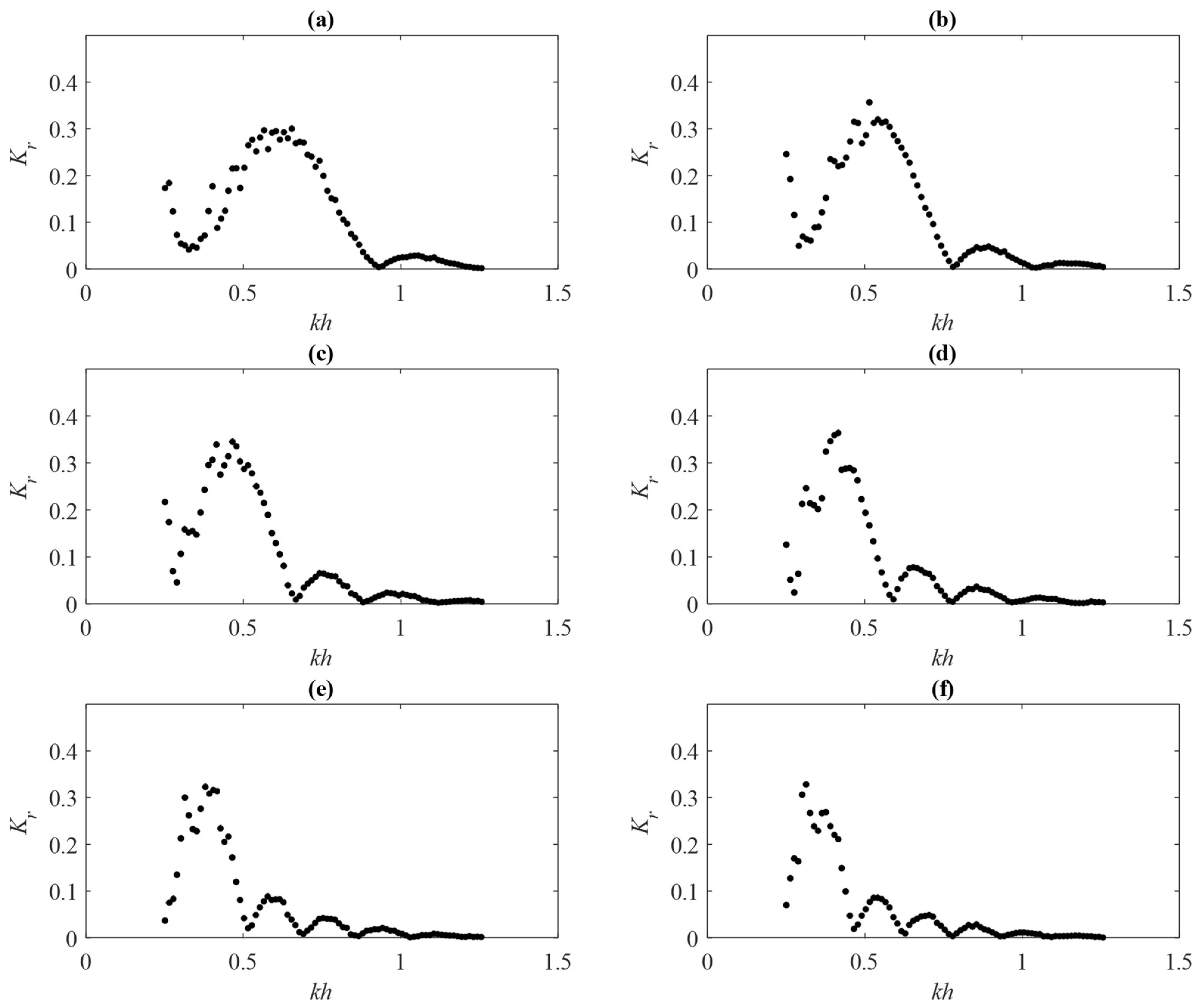
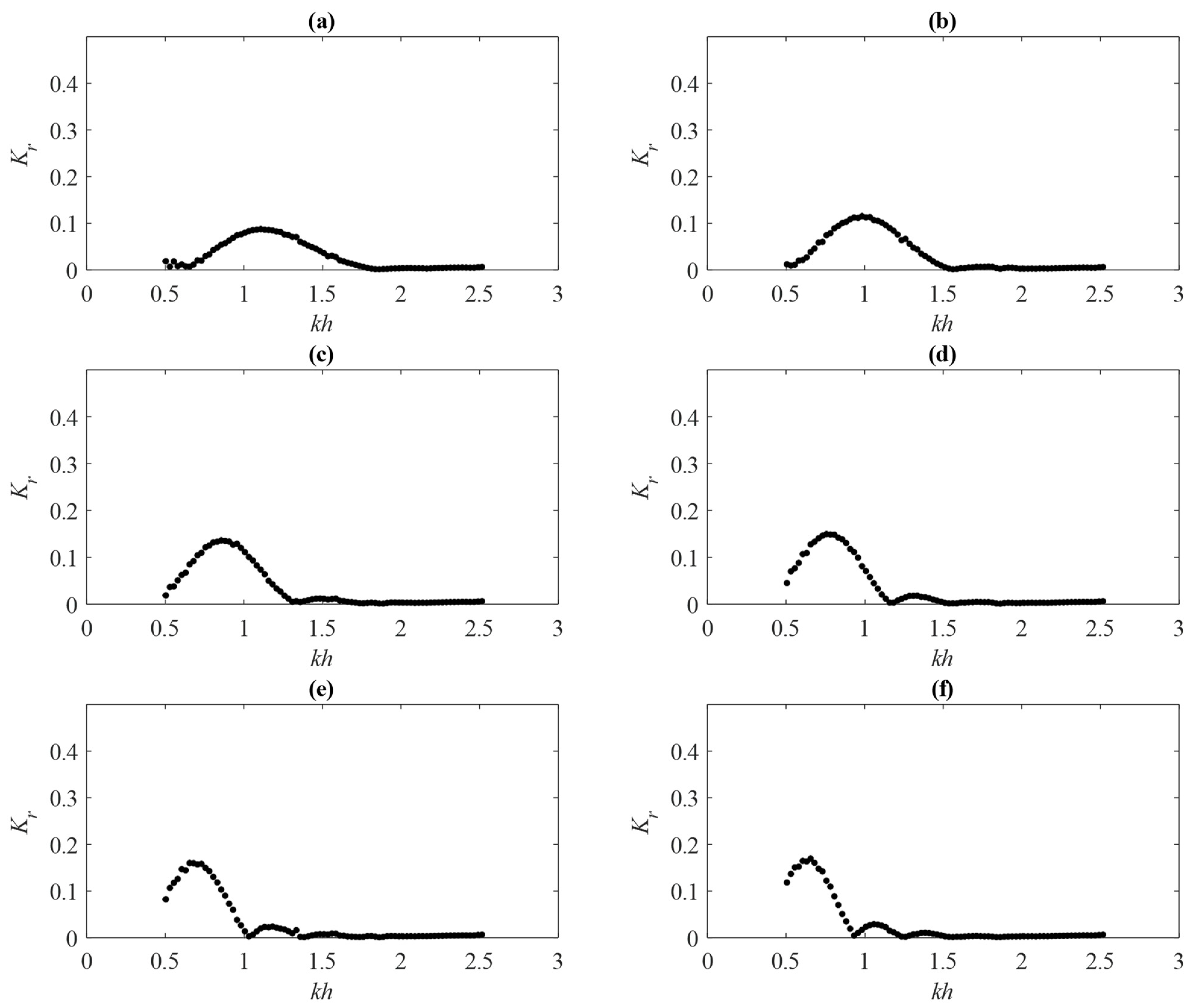
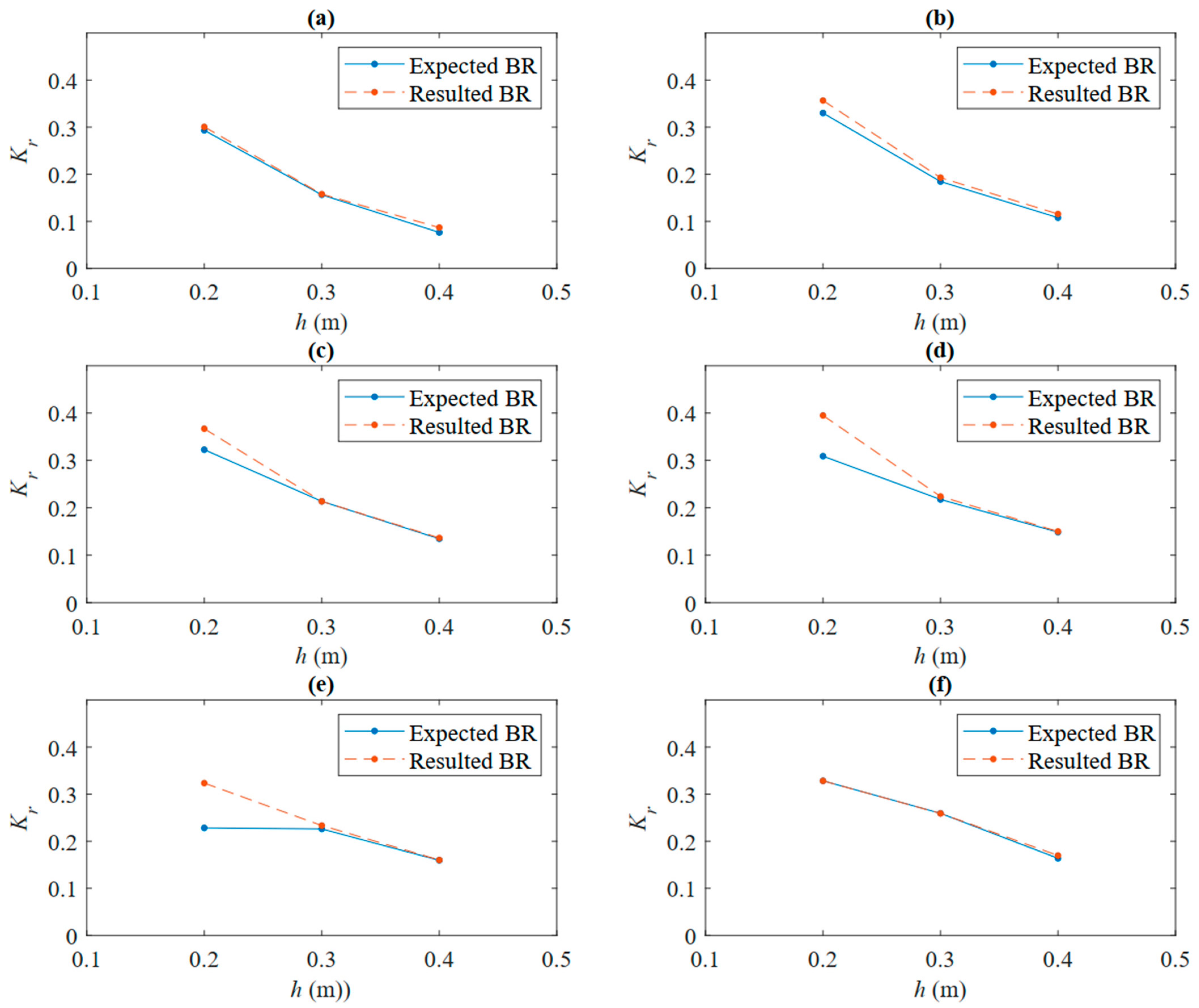
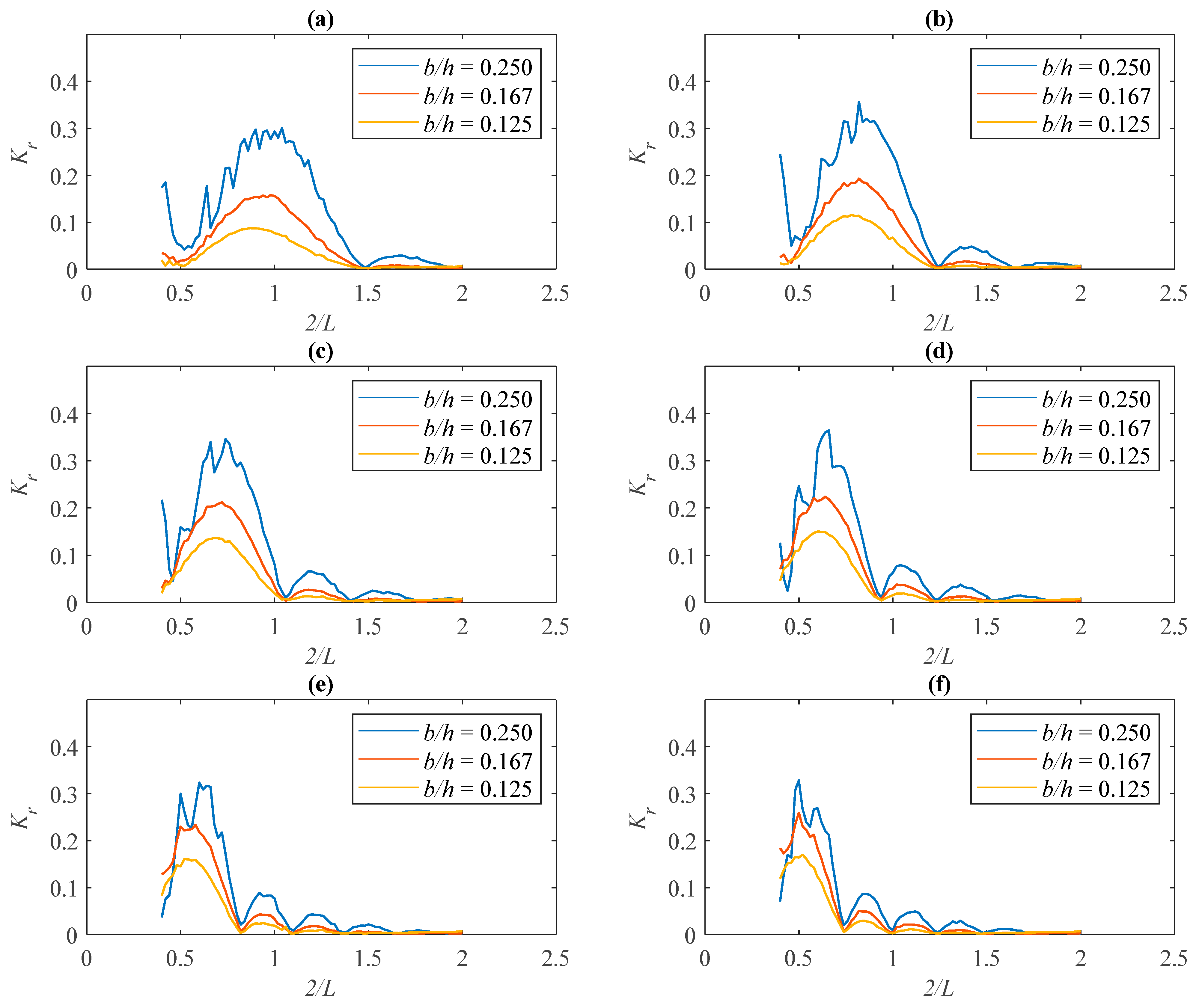
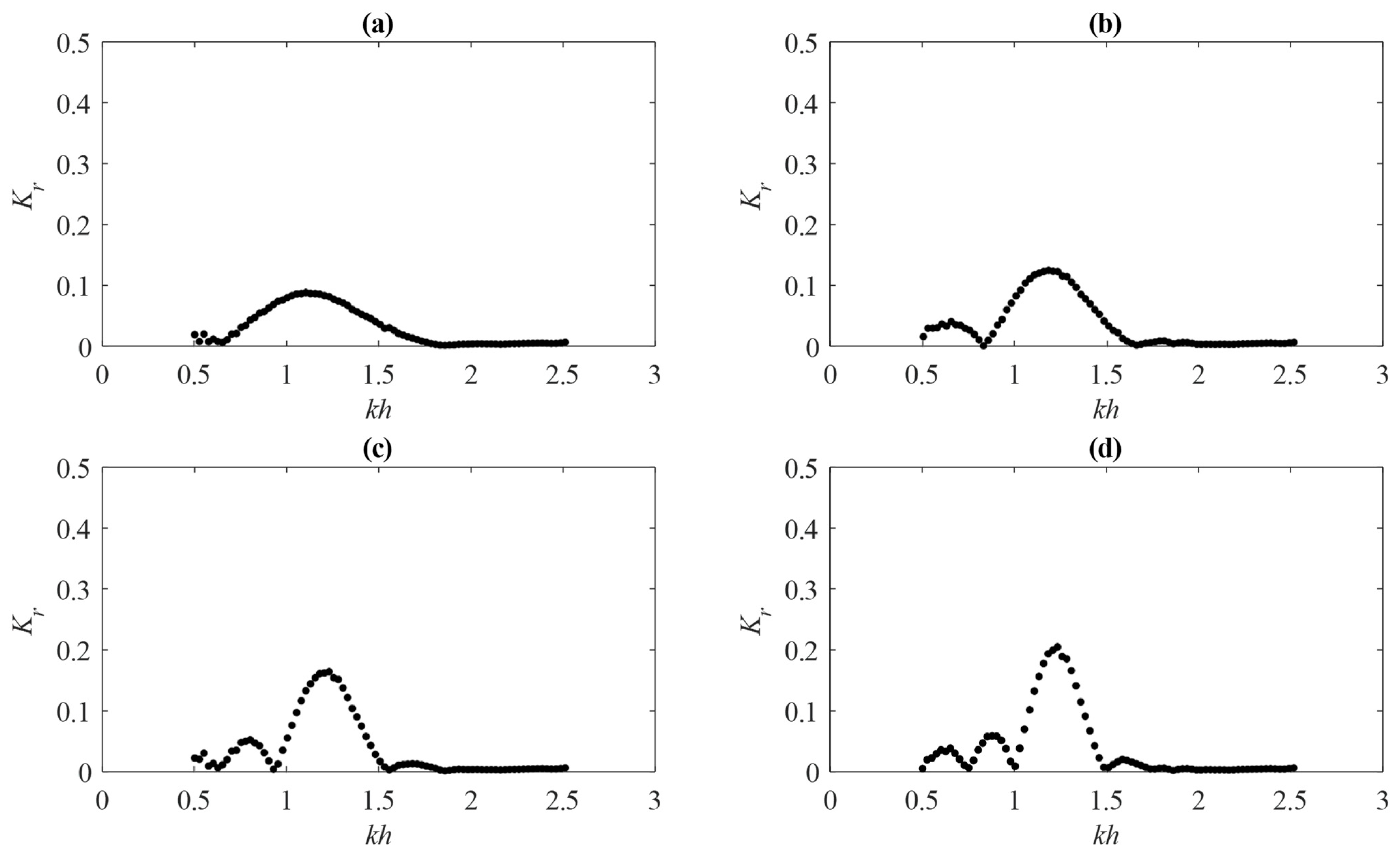
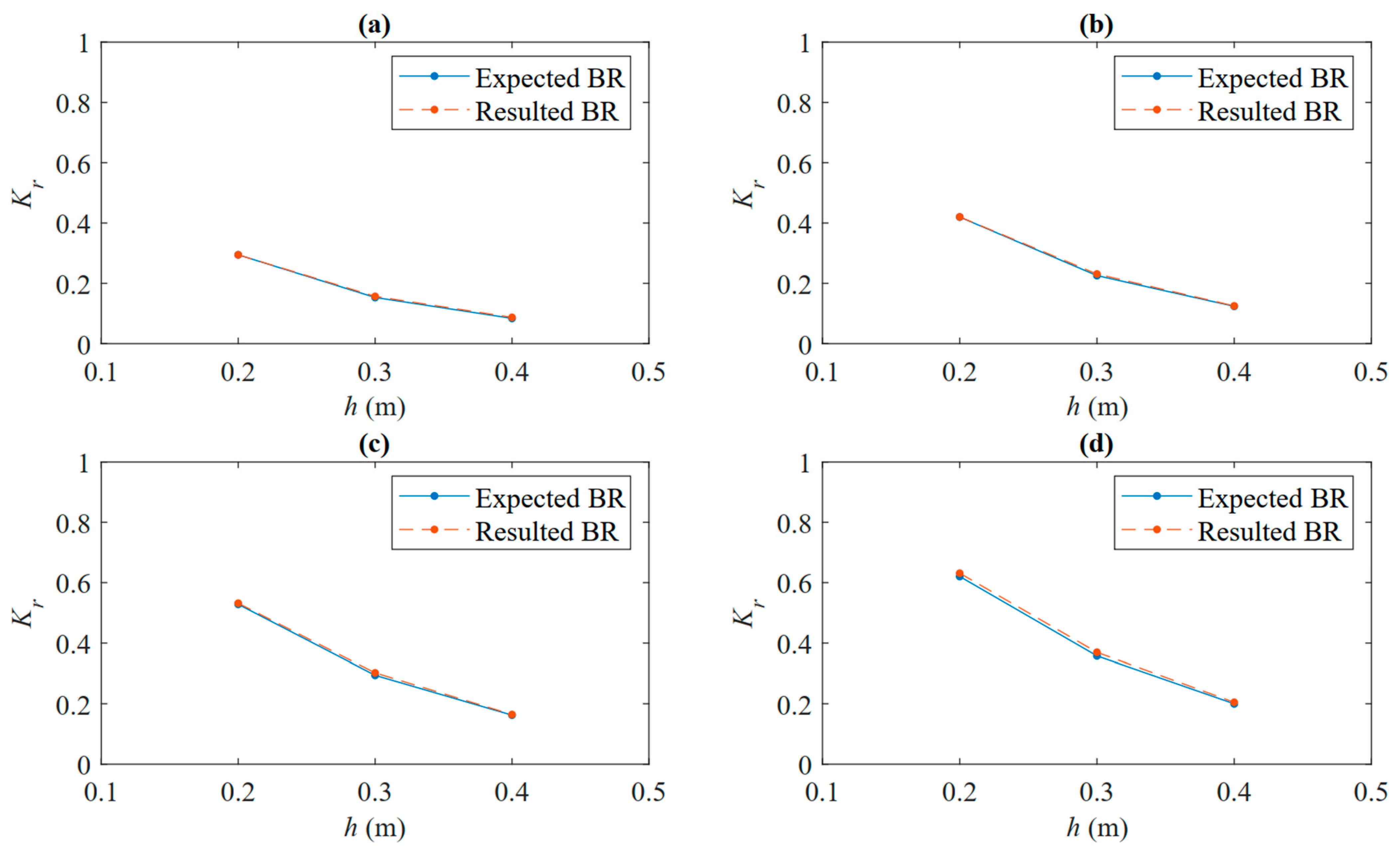
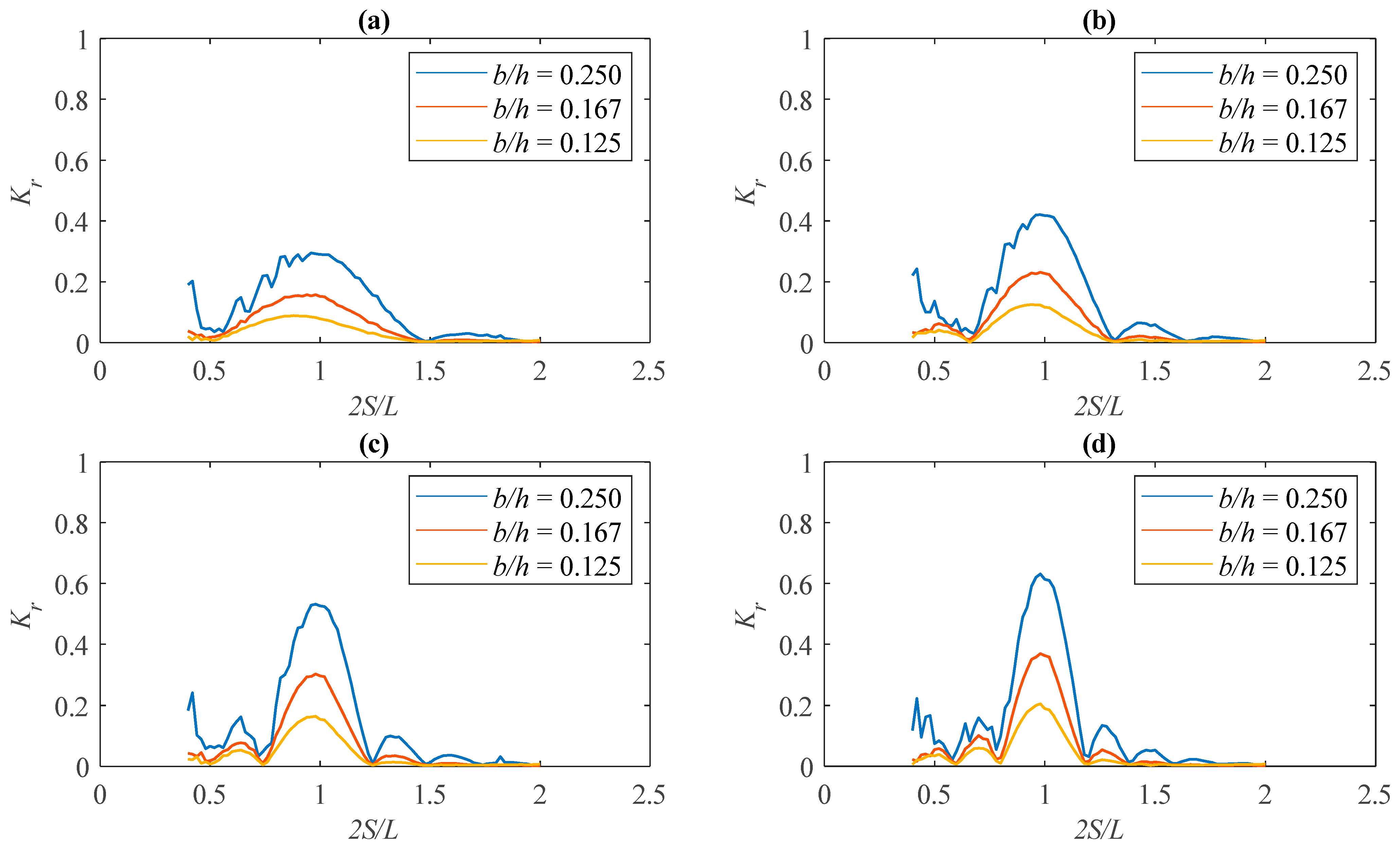
4.1. Bragg Resonance on Different Structural Wavelength

As previously discussed in the introduction, Bragg resonance is the peak point of the prominent resonance of the reflection coefficient. This subsection explores the relationship between periodically submerged breakwater of different wavelengths and at different water depths. First, we examine the influence of the ripple structural wavelength S on the reflection coefficient Kr. The study considers mean water depths of h = 0.2 m, 0.3 m, and 0.4 m, with S = 1.0, 1.2, 1.4, 1.6, 1.8, and 2.0 and b = 0.05 m as the wavelengths and amplitude of the periodically submerged breakwater, respectively; N = 2 is the number of the periodically submerged breakwater.
The reflection coefficient Kr results are presented in Figure 3, Figure 4 and Figure 5; three phenomena were noticed around the resonance of the reflection coefficients Kr: length, positioning, and number of resonances. As the structural wavelength S increases from 1 to 2 m, the bandwidth becomes narrower, with a leftward shift in 2S/L from 0.96 to 1.06 at 0.2 m, 0.98 to 1.02 at 0.3 m, and 0.92 to 1.02 at 0.4 m water depth, and frequent occurrence of the resonance from approximately 2 to 6. More waves are reflected at different wave properties when the periodically submerged breakwater have a shorter structural wavelength, owing to their wider resonance in the reflection coefficient. It is not surprising that the magnitude of their reflection coefficients Kr decreases as the mean water depth increases from 0.2 to 0.4 m; however, this broadens the resonance of the reflection coefficient.
The reflection coefficient is the standard way to report the Bragg resonance phenomenon, so we zoomed in to the peak of the first resonance of the reflection coefficient to provide greater detail of the study of Bragg resonance with different structural wavelengths S. Bragg resonance is known to occur approximately when the incident wavelength is twice the structural wavelength 2 S / L 1 . The deviation of Bragg resonance around this point at different structural wavelengths S at 0.2 m, 0.3 m, and 0.4 m water depth are shown in Figure 6, Figure 7 and Figure 8, respectively. The reflection coefficient Kr around the expected BR at 2 S / L = 1 (Table 2) becomes more precise as the structural wavelength S decreases and increases with water depth h. This is another way to show that periodically submerged breakwater with shorter structural wavelengths is capable of having a high reflection coefficient Kr at different incident wavelengths L. However, the slight deviation of the reflection coefficient Kr for the expected BR and the resulted BR in Figure 4 as the structural wavelength S varies, is a result of the shallow water, 0.2 m in depth, as the variation becomes minimal as the water depth increases to 0.4 m (Figure 7 and Figure 8). The mutual trend of both the expected BR and the resulted BR shows an increase in the Bragg resonance as the structural wavelength S increases.
Figure 9 shows the relation of the expected BR and resulted BR in different water depth h at different structural wavelengths S. Bragg resonance decreases as the water depth h increases from 0.2 to 0.4 m as the structural amplitude b = 0.05   m is constant. Similarly, as shown in Figure 10, the differences in the reflection coefficient at a single structural length with different water depths are resonance peaks. The reduction in the water column between the structure and water surface caused the Bragg resonance to increase as the impact of the structure on the incoming wave increased as the water depth decreased. Additionally, an increase in structural wavelength S from 1 to 2 m with a slight increase in the Bragg resonance of 0.300 to 0.328 at 0.2 m, 0.158 to 0.259 at 0.3 m, and 0.087 to 0.170 at 0.4 m water depth; however, its inverse relationship with the resonance’s bandwidth is more pronounced. The bandwidth, leftward shift, and frequent occurrence of resonance are similar at different water depths h for each structural wavelength S.

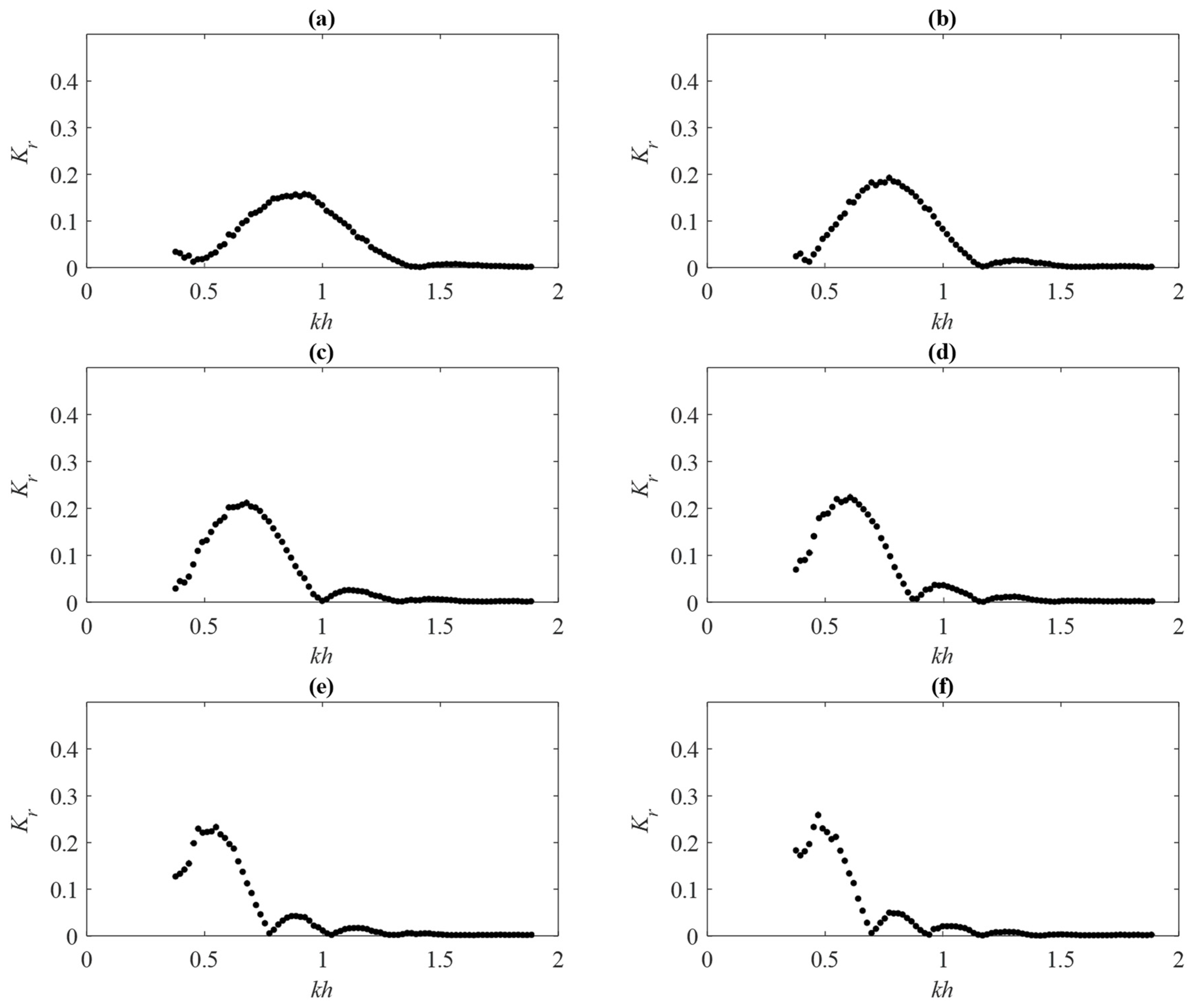
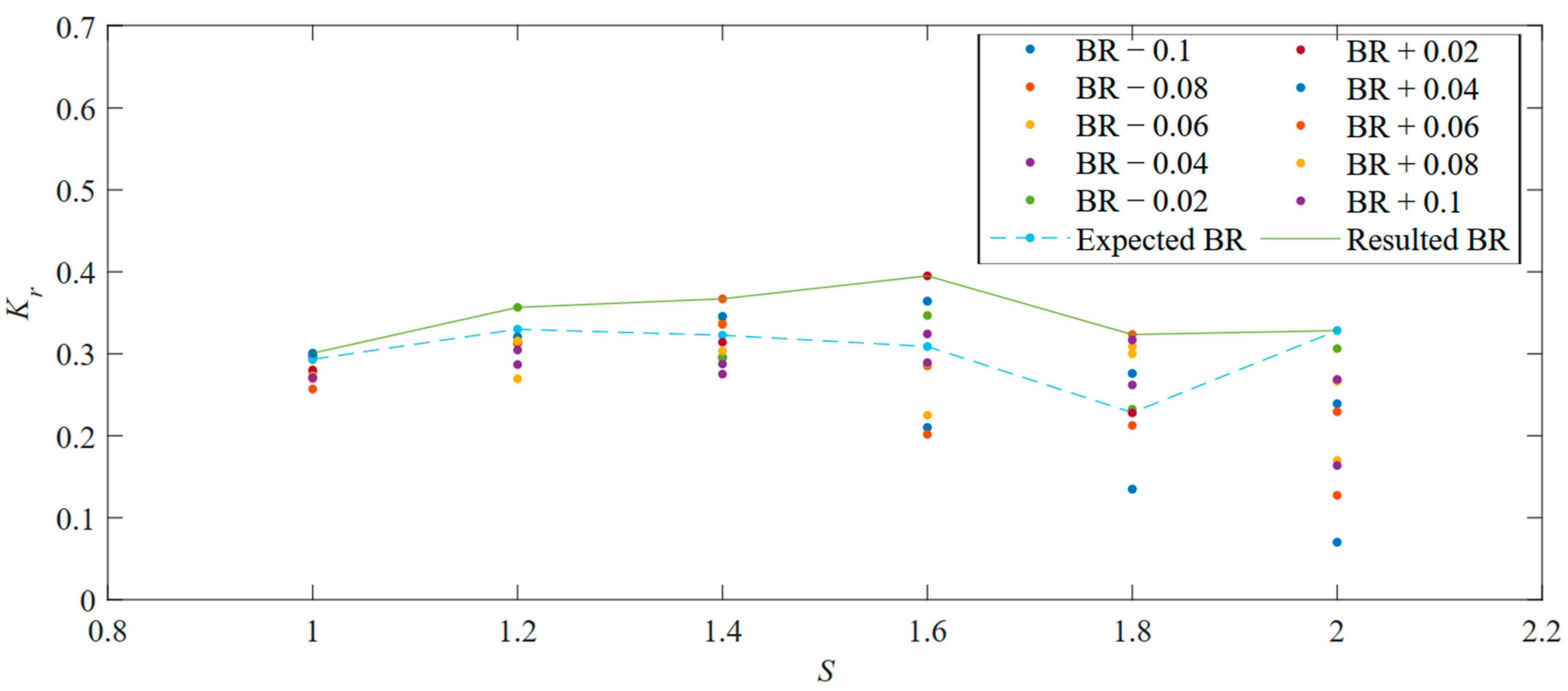
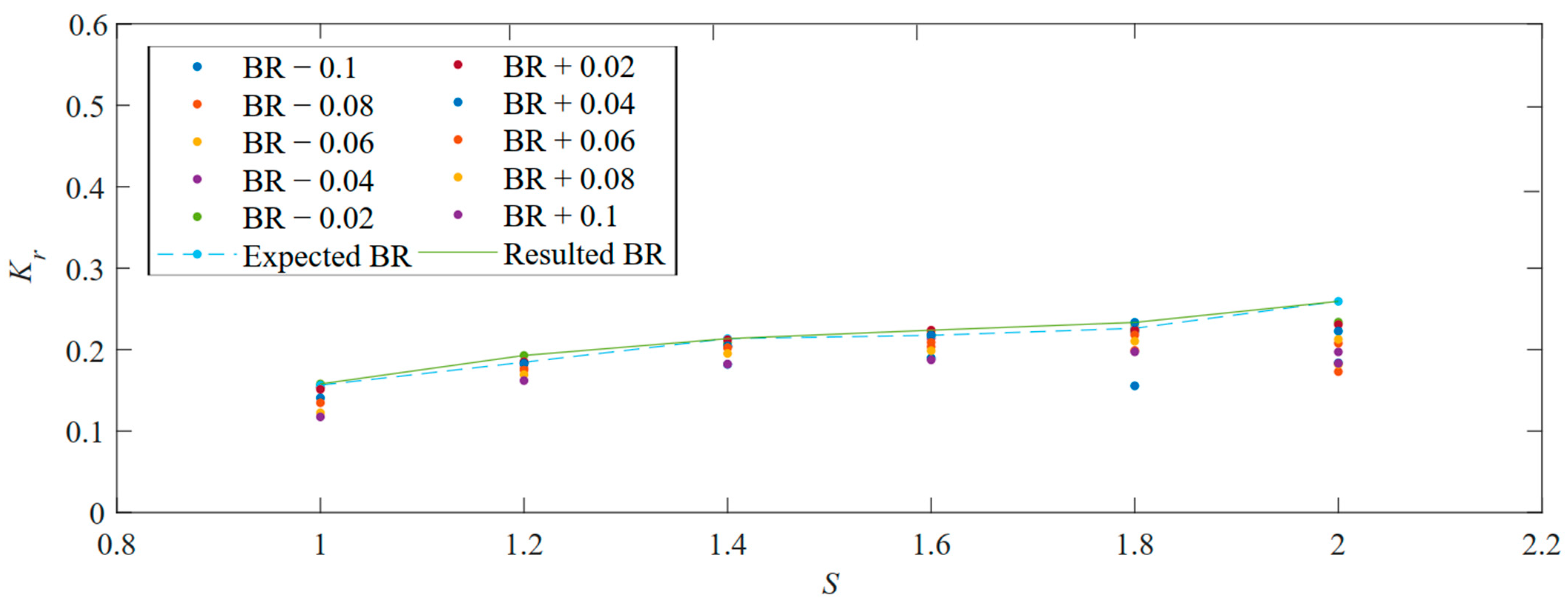
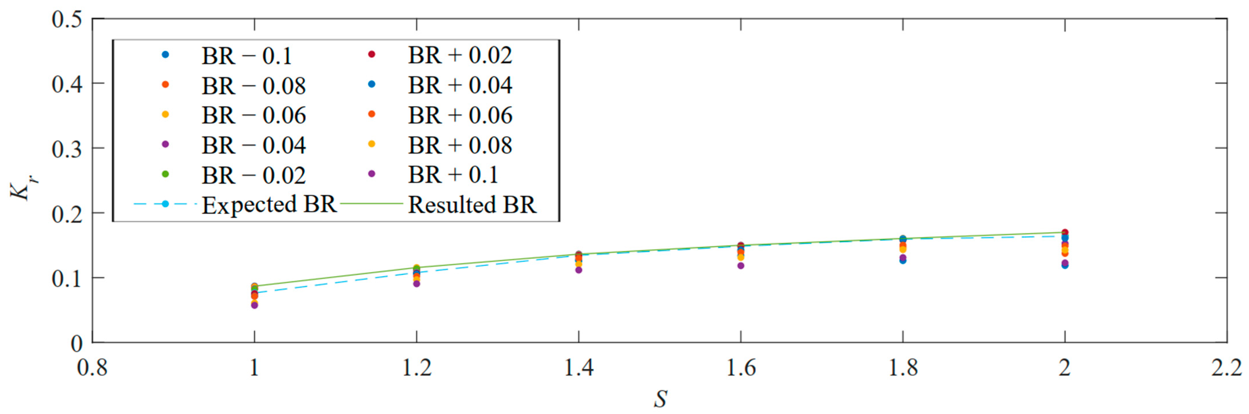
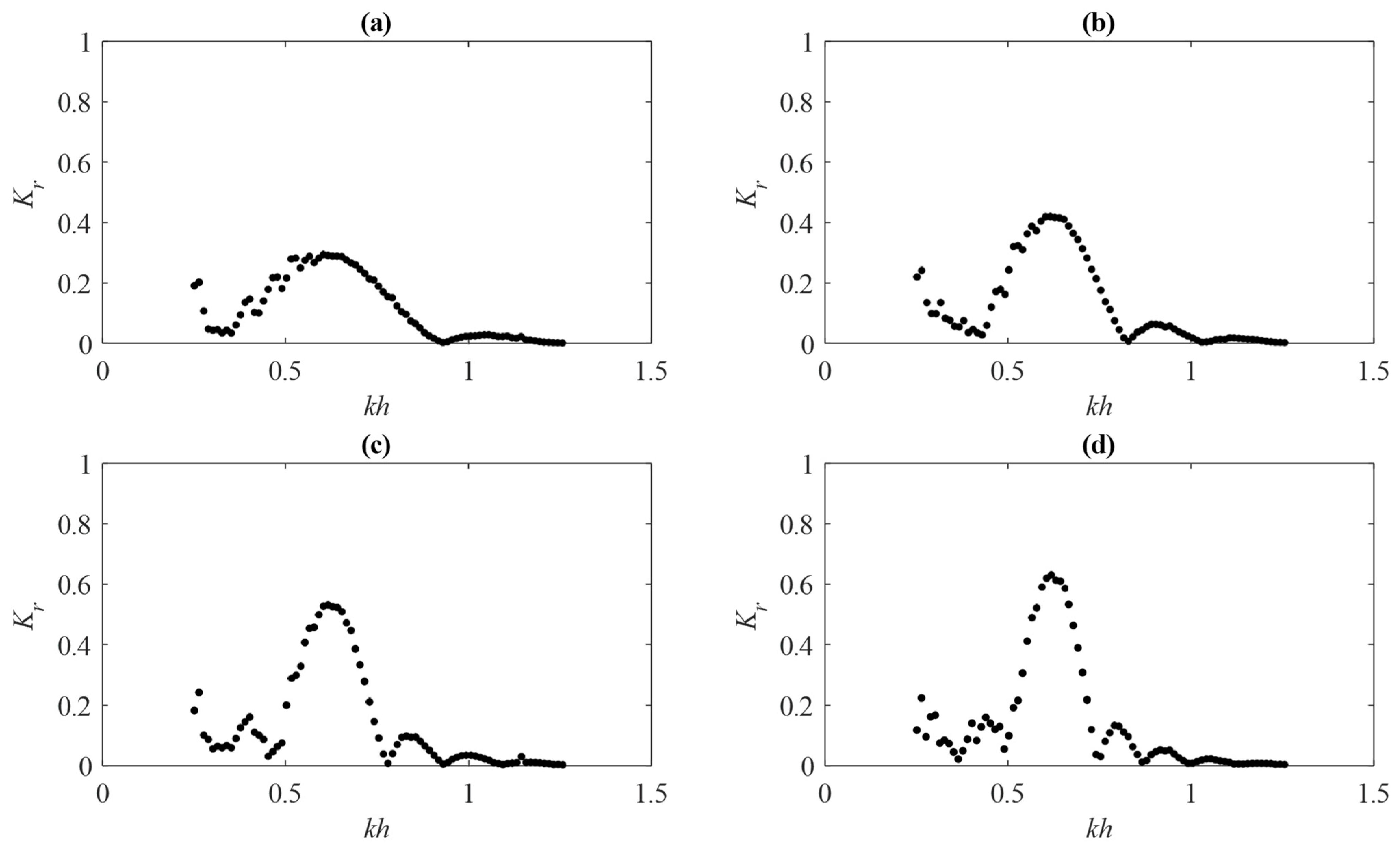
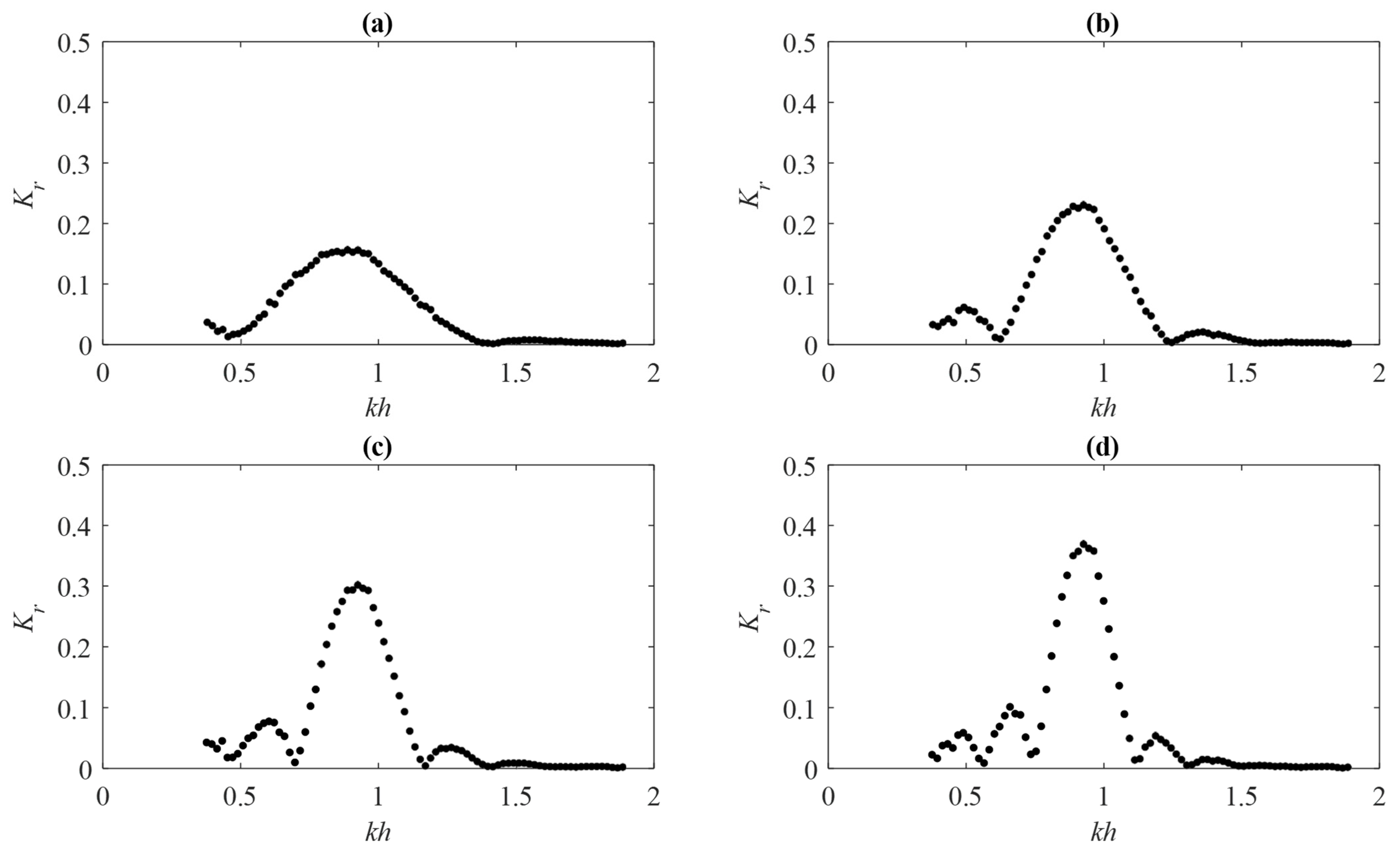
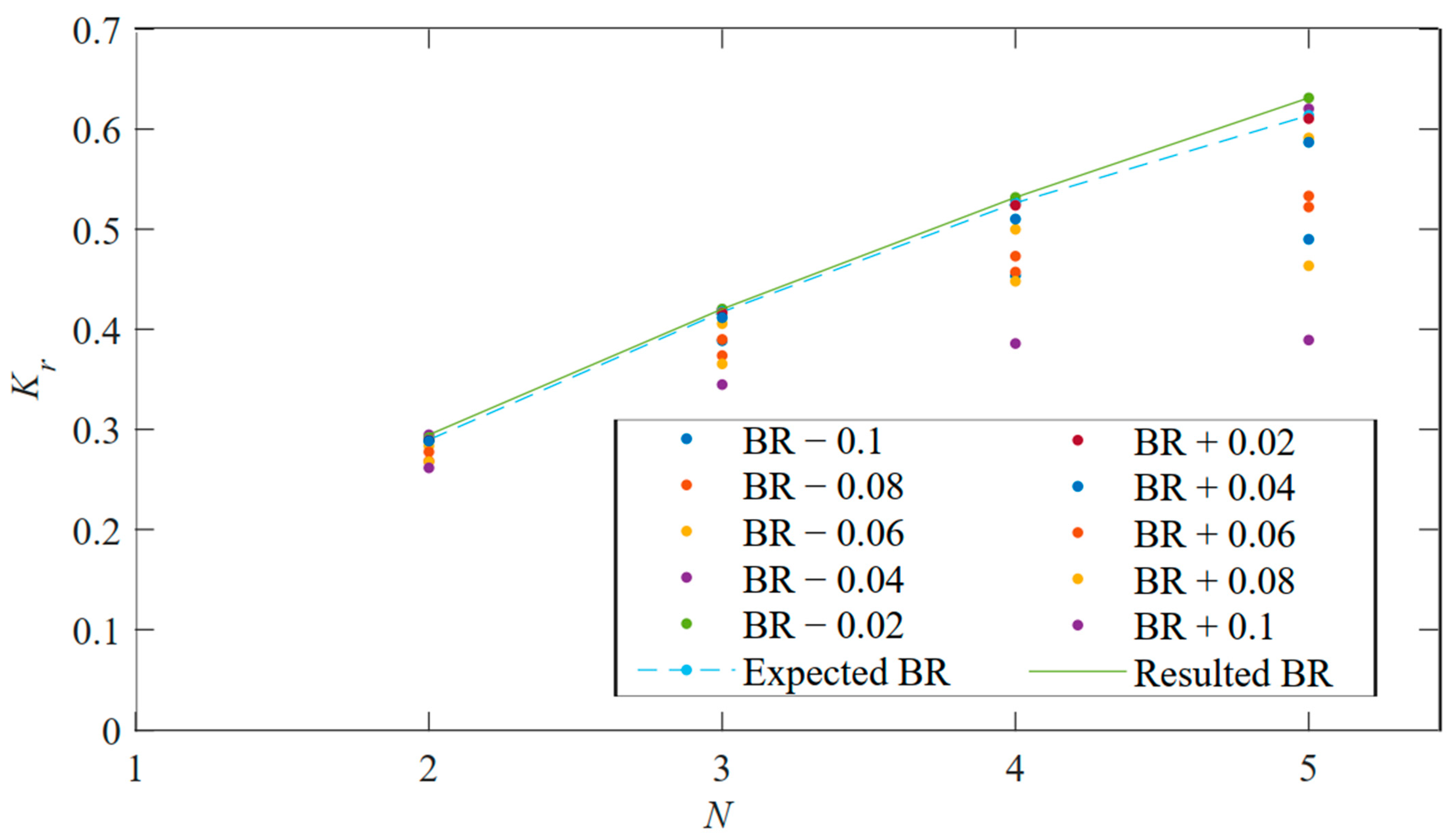
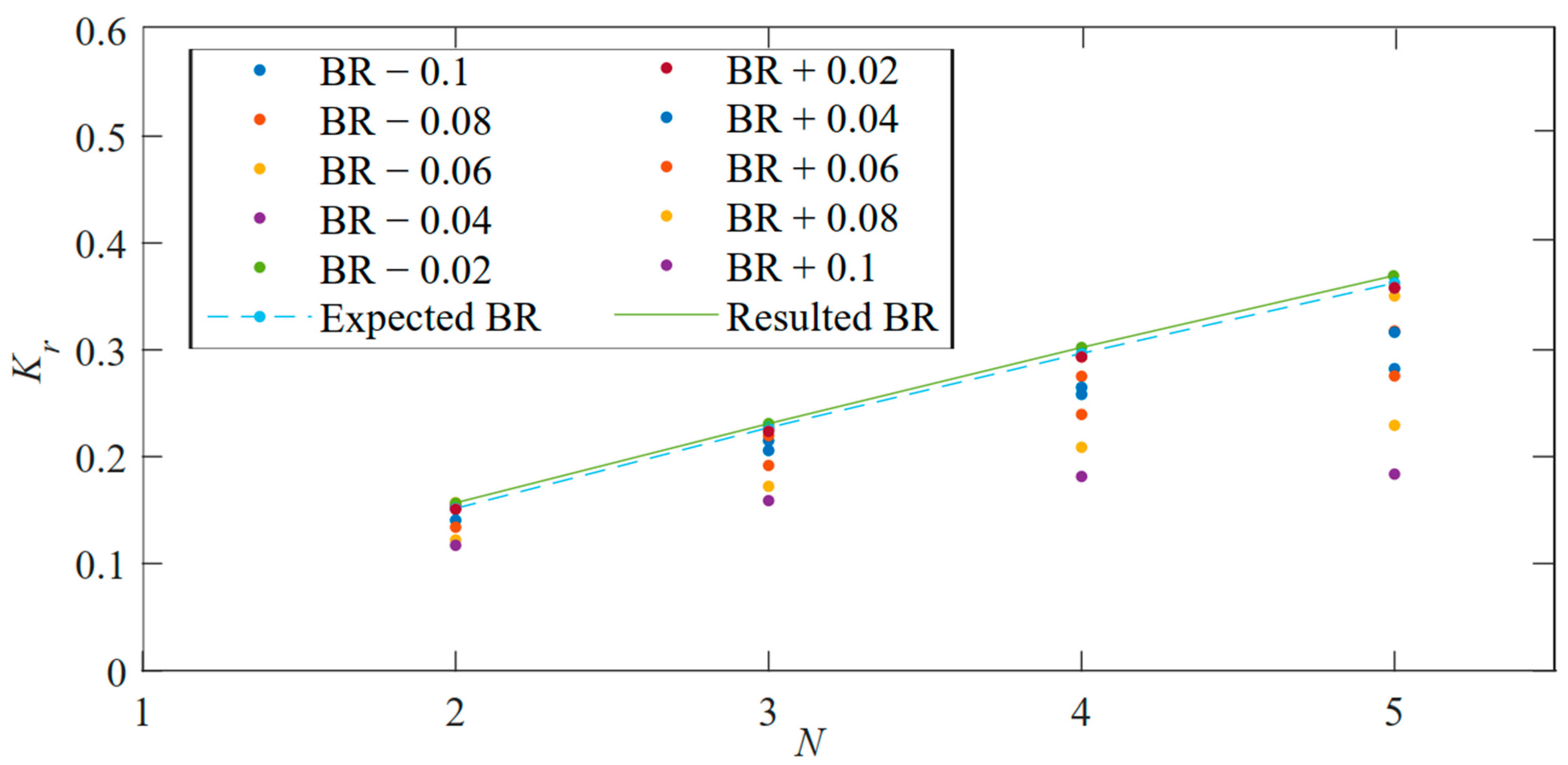
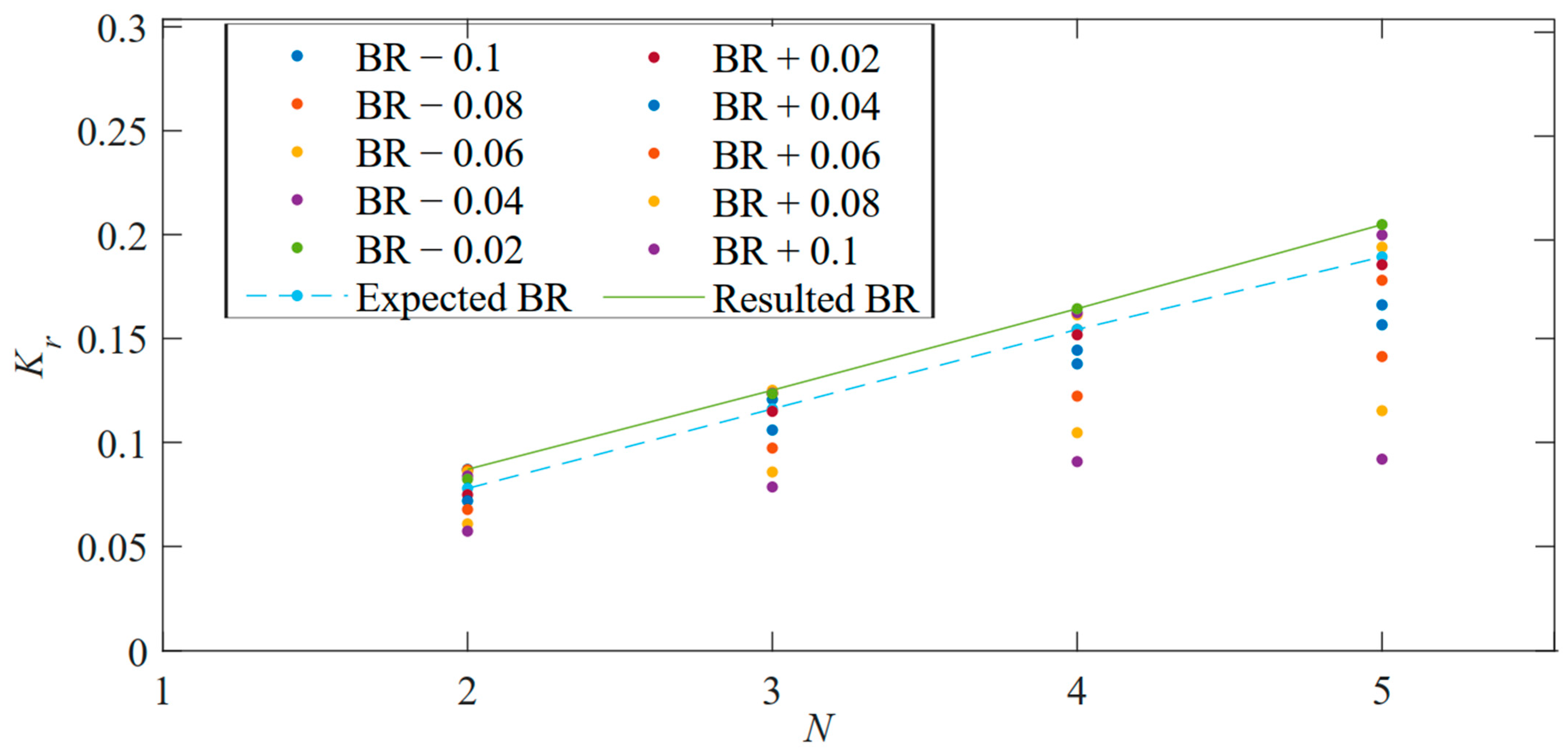
4.2. Bragg Resonance on Multiple Periodically Submerged Breakwater

The multiple periodically submerged breakwaters range from 2 to 5, with each ripple having a 1 m structural wavelength S and 0.05 m ripple amplitude. The influence of multiple periodically submerged breakwater on the reflection coefficient Kr was studied at mean water depth of 0.2 m, 0.3 m, and 0.4 m.
The length, positioning, and resonance numbers of reflection coefficient Kr are shown in Figure 11, Figure 12 and Figure 13 show that as the number of ripples increases from two to five ripples, the prominent resonance of the reflection coefficient Kr; reduces in bandwidth length and increases in their peak values of 0.295 to 0.631 at 0.2 m, 0.157 to 0.370 at 0.3 m, and 0.087 to 0.205 at 0.4 m water depth. The positioning of the resonance is the same at each water depth, with their peaks occurring at 0.616, 0.924, and 1.232 kh in 0.2, 0.3, and 0.4 m mean water depth, respectively. Although the resonance bandwidth decreases as the number of ripples increases, more resonance occurs around the prominent resonance of the reflection coefficient, Kr.
For multiple periodically submerged breakwater, Bragg resonance occurs at the peak of the prominent resonance in the reflection coefficient when 2 S / L 1 . Figure 14, Figure 15 and Figure 16 shows the variation of Bragg resonance in 2 to 5 ripples beds at a mean water depth of 0.2 m, 0.3 m, and 0.4 m, respectively. The consistency in the deviation of the resulted BR from the expected BR as the number of ripples increases has also shown that at a single water depth, the point at which Bragg resonance occurs at approximately 2S/L is constant at a finite number of periodically submerged breakwater; in this case, it occurs at 2 S / L = 0.98 . Furthermore, as the mean water depth h increases from 0.2 to 0.4 m, the deviation of the resulted BR from the expected BR becomes more significant, which is also evidence of a shift in the Bragg resonance when there is a change in water depth. In addition, the increase in Bragg resonance as the number of ripples increases results from more structures being introduced, leading to more area being covered by the structures, and more waves being reflected.
The reflection coefficient Kr values of the expected BR and resulted BR at different mean water depths of 0.2, 0.3, and 0.4 m were compared at a constant 1.0 m structural wavelengths S, as shown in Figure 17. The results show that the influence of the change in water depth on the reflection coefficient Kr values of the expected BR and the resulted BR is negligible; however, as the number of ripples increases from 2 to 5, the difference in their values becomes significant. These differences can also be observed in Figure 14, Figure 15 and Figure 16. as the number of periodically submerged breakwater increases, the precision of the reflection coefficient Kr values around the expected BR increases.
Figure 18 shows the similarity in the reflection coefficient Kr curve of the multiple ripples at different water depths; bandwidth, position, and number of resonances are similar at each periodically submerged breakwater number. However, as the ratio of the structural amplitude b to the mean water depth h increases from 0.125 to 0.250, the peak of the resonance of the reflection coefficient Kr increases at each number of periodically submerged breakwater with a slight shift to the right, and more waves are reflected as the number of ripples increases.

5. Conclusions

A detailed study on Bragg resonance was carried out using the SWASH model at 0.2, 0.3, and 0.4 m water depths, 1 to 5 m structural lengths, and 2 to 4 periodically submerged breakwater. The model has previously been numerically used in similar cases as in this study and was validated using an experimental, theoretical, and numerical results from previous studies. Using this numerical model, the influence of multiple ripple beds and their length on the Bragg resonance, the peak point of the prominent resonance of the reflection coefficient, was studied. The following conclusions were drawn from a comparison of the results.
The resonances of the reflection coefficient become higher and narrower as the structural wavelength S and the number of ripples beds N increase from 1 to 5 m and 2 to 4, respectively. The wave energy reflected by an increase in the number of ripples increases, unlike the increasing structural wavelength, which subsequently reduces the wave energy.
The values of Bragg resonances slightly increase as the structural wavelength S increases from 1 to 2 m, with a leftward shift in 2S/L at various water depths. However, Bragg resonances rapidly increase as the number of periodically submerged breakwaters increases, with no shift in its point of occurrence at 2 S / L = 0.98 . The shift in the point of occurrence of Bragg resonance is affected by changes in water depth, but not by changes in its value.
The dispersion of the reflection coefficient Kr values of the resulted BR from the expected BR is a phenomenon that shows why Bragg resonance will not occur mainly at 2 S / L = 1 . The differences in the values are associated with the changes in the number of periodically submerged breakwater, and the shift in the point of occurrence is influenced by the water depth and structural length.sa.

Author Contributions

T.E.O.: conceptualization, methodology, software, data curation, formal analysis, investigation, and writing—original draft. X.Z.: supervision, funding, Writing—review. All authors have read and agreed to the published version of the manuscript.

Funding

This study was supported by the National Natural Science Foundation of China (Grant Nos. 51979245) and The Chinese Government Scholarship.

Acknowledgments

We appreciate Min Luo, Elnalee Baguya, Li Mengyu, Fu Ding, Zhan Yi, Wang Su, Ye Zhouteng, Yin Mingjian, Zong Yiyang, Xie Yulin, Lv Chaofan, Zhou Yuwei, and Liu Zhuqin for their basic discussion and contribution.

Conflicts of Interest

The authors declare no conflict of interest.

References

  1. Blondeaux, P.J. Sand ripples under sea waves Part 1. Ripple formation. J. Fluid Mech. 1990, 218, 1–17. [Google Scholar] [CrossRef]
  2. Daniel, M.; Alymov, V.; Chang, Y.; Jette, C. Wave-formed sand ripples at Duck, North Carolina. J. Geophys. Res. Ocean 2001, 106, 22575–22592. [Google Scholar]
  3. Liu, H.W.; Li, X.F.; Lin, P.Z. Analytical study of Bragg resonance by singly periodic sinusoidal ripples based on the modified mild-slope equation. Coast. Eng. 2019, 150, 121–134. [Google Scholar] [CrossRef]
  4. Stegner, A.; Wesfreid, J.E. Dynamical evolution of sand ripples under water. Phys. Rev. 1999, 60, R3487. [Google Scholar] [CrossRef] [Green Version]
  5. Yu, J.; Mei, C. Formation of sand bars under surface waves. J. Fluid Mech. 2000, 416, 315–348. [Google Scholar] [CrossRef]
  6. Mei, C.C.; Hara, T.; Naciri, M. Note on Bragg Scattering of Water-Waves by Parallel Bars on the Seabed. J. Fluid Mech. 1988, 186, 147–162. [Google Scholar] [CrossRef]
  7. Jeon, C.H.; Cho, Y.S. Bragg reflection of sinusoidal waves due to trapezoidal submerged breakwaters. Ocean Eng. 2006, 33, 2067–2082. [Google Scholar] [CrossRef]
  8. Wang, S.K.; Hsu, T.W.; Tsai, L.H.; Chen, S.H. An application of Miles’ theory to Bragg scattering of water waves by doubly composite artificial bars. Ocean Eng. 2006, 33, 331–349. [Google Scholar] [CrossRef]
  9. Liu, H.W.; Luo, H.; Zeng, H.D. Optimal Collocation of Three Kinds of Bragg Breakwaters for Bragg Resonant Reflection by Long Waves. J. Waterw. Port Coast. Ocean Eng. 2015, 141, 04014039. [Google Scholar] [CrossRef]
  10. Liu, H.W.; Liu, Y.; Lin, P. Bloch band gap of shallow-water waves over infinite arrays of parabolic bars and rectified cosinoidal bars and Bragg resonance over finite arrays of bars. Ocean Eng. 2019, 188, 106235. [Google Scholar] [CrossRef]
  11. Davies, A.G. On the Interaction between Surface-Waves and Undulations on the Seabed. J. Mar. Res. 1982, 40, 331–368. [Google Scholar]
  12. Davies, A.G.; Heathershaw, A.D. Surface-Wave Propagation over Sinusoidally Varying Topography. J. Fluid Mech. 1984, 144, 419–443. [Google Scholar] [CrossRef]
  13. Zhang, J.S.; Jeng, D.S.; Liu, P.L.F.; Zhang, C.; Zhang, Y. Response of a porous seabed to water waves over permeable submerged breakwaters with Bragg reflection. Ocean Eng. 2012, 43, 1–12. [Google Scholar] [CrossRef]
  14. Gao, J.L.; Ma, X.Z.; Dong, G.H.; Chen, H.Z.; Liu, Q.; Zang, J. Investigation on the effects of Bragg reflection on harbor oscillations. Coast. Eng. 2021, 170, 103997. [Google Scholar] [CrossRef]
  15. Huan-Wen, L.; Zhou, X.-M. Explicit modified mild-slope equation for wave scattering by piecewise monotonic and piecewise smooth bathymetries. J. Eng. Math. 2014, 87, 29–45. [Google Scholar] [CrossRef]
  16. Huan-Wen, L.; Zeng, H.-D.; Huang, H.-D. Bragg resonant reflection of surface waves from deep water to shallow water by a finite array of trapezoidal bars. Appl. Ocean Res. 2020, 94, 101976. [Google Scholar] [CrossRef]
  17. Cho, Y.S.; Lee, J.I.; Kim, Y.T. Experimental study of strong reflection of regular water waves over submerged breakwaters in tandem. Ocean Eng. 2004, 31, 1325–1335. [Google Scholar] [CrossRef]
  18. Cho, Y.S.; Yoon, S.B.; Lee, J.I.; Yoon, T.H. A Concept of Beach Protection with Submerged Breakwaters. J. Coast. Res. 2001, 671–678. [Google Scholar]
  19. Chang, H.K.; Liou, J.C. Long wave reflection from submerged trapezoidal breakwaters. Ocean Eng. 2007, 34, 185–191. [Google Scholar] [CrossRef]
  20. Huan-Wen, L.; Luo, J.-X.; Lin, P.; Liu, R. Analytical Solution for Long-Wave Reflection by a General Breakwater or Trench with Curvilinear Slopes. J. Eng. Mech. 2013, 139, 229–245. [Google Scholar] [CrossRef]
  21. Mei, C.C. Resonant Reflection of Surface-Water Waves by Periodic Sandbars. J. Fluid Mech. 1985, 152, 315–335. [Google Scholar] [CrossRef]
  22. Miles, J.W. Oblique Surface-Wave Diffraction by a Cylindrical Obstacle. Dyn. Atmos. Ocean. 1981, 6, 121–123. [Google Scholar] [CrossRef]
  23. Liang, B.C.; Wu, G.X.; Liu, F.S.; Fan, H.R.; Li, H.J. Numerical study of wave transmission over double submerged breakwaters using non-hydrostatic wave model. Oceanologia 2015, 57, 308–317. [Google Scholar] [CrossRef] [Green Version]
  24. Zijlema, M.; Stelling, G.; Smit, P. SWASH: An operational public domain code for simulating wave fields and rapidly varied flows in coastal waters. Coast. Eng. 2011, 58, 992–1012. [Google Scholar] [CrossRef]
  25. Rijnsdorp, D.P.; Smit, P.B.; Zijlema, M. Non-hydrostatic modelling of infragravity waves under laboratory conditions. Coast. Eng. 2014, 85, 30–42. [Google Scholar] [CrossRef]
  26. Heathershaw, A.D. Seabed-wave resonance and sand bar growth. Nature 1982, 296, 343–345. [Google Scholar] [CrossRef]
  27. Goda, Y.; Suzuki, Y. Estimation of incident and reflected waves in random wave experiments. In Proceedings of the 15th International Conference on Coastal Engineering, Honolulu, HI, USA, 11–17 July 1976; ASCE: Reston, VA, USA, 1976; pp. 828–845. [Google Scholar]
Figure 1. Schematic numerical model setup for regular wave over periodically submerged breakwater ( N = 2 ).
Jmse 11 00650 g001
Figure 2. Validation of the present numerical model with experiment [12] and analytical solution [3] data. (a) N = 2 (b) N = 4 .
Jmse 11 00650 g002
Figure 3. Reflection coefficient of 2 periodically submerged breakwater with different structural wavelengths at 0.2 m water depth. (a) S = 1.0 m (b) S = 1.2 m (c) S = 1.4 m (d) S = 1.6 m (e) S = 1.8 m (f) S = 2.0 m.
Jmse 11 00650 g003
Figure 4. Reflection coefficient of 2 periodically submerged breakwaters with different structural wavelengths at 0.3 m water depth: (a) S = 1.0 m (b) S = 1.2 m (c) S = 1.4 m (d) S = 1.6 m (e) S = 1.8 m (f) S = 2.0 m.
Jmse 11 00650 g004
Figure 5. Reflection coefficient of 2 periodically submerged breakwaters with different structural wavelengths at 0.4 m water depth. (a) S = 1.0 m (b) S = 1.2 m (c) S = 1.4 m (d) S = 1.6 m (e) S = 1.8 m (f) S = 2.0 m.
Jmse 11 00650 g005
Figure 6. Bragg resonance of 2 periodically submerged breakwaters along different structural wavelengths at 0.2 m water depth.
Jmse 11 00650 g006
Figure 7. Bragg resonance of 2 periodically submerged breakwaters along different structural wavelengths at 0.3 m water depth.
Jmse 11 00650 g007
Figure 8. Bragg resonance of 2 periodically submerged breakwaters along different structural wavelengths at 0.4 m water depth.
Jmse 11 00650 g008
Figure 9. Bragg resonance of 2 periodically submerged breakwaters along different structural wavelengths at different water depths: (a) S = 1.0 m (b) S = 1.2 m (c) S = 1.4 m (d) S = 1.6 m (e) S = 1.8 m (f) S = 2.0 m.
Jmse 11 00650 g009
Figure 10. Reflection coefficient of 2 periodically submerged breakwaters along different structural wavelength at different water depths: (a) S = 1.0 m (b) S = 1.2 m (c) S = 1.4 m (d) S = 1.6 m (e) S = 1.8 m (f) S = 2.0 m.
Jmse 11 00650 g010
Figure 11. Reflection coefficient of multiple periodically submerged breakwater with 1.0 m wavelength at 0.2 m water depth: (a) N = 2 (b) N = 3 (c) N = 4 (d) N = 5 .
Jmse 11 00650 g011
Figure 12. Reflection coefficient of multiple periodically submerged breakwaters with 1.0 m wavelength at 0.3 m water depth: (a) N = 2 (b) N = 3 (c) N = 4 (d) N = 5 .
Jmse 11 00650 g012
Figure 13. Reflection coefficient of multiple periodically submerged breakwaters with 1.0 m wavelength at 0.4 m water depth: (a) N = 2 (b) N = 3 (c) N = 4 (d) N = 5 .
Jmse 11 00650 g013
Figure 14. Bragg resonance of multiple periodically submerged breakwaters with 1.0 m wavelength at 0.2 m water depth.
Jmse 11 00650 g014
Figure 15. Bragg resonance of multiple periodically submerged breakwater with 1.0 m wavelength at 0.3 m water depth.
Jmse 11 00650 g015
Figure 16. Bragg resonance of multiple periodically submerged breakwaters with 1.0 m wavelength at 0.4 m water depth.
Jmse 11 00650 g016
Figure 17. Bragg resonance of multiple periodically submerged breakwaters with 1.0 m structural wavelength S at different water depths. (a) N = 2 (b) N = 3 (c) N = 4 (d) N = 5 .
Jmse 11 00650 g017
Figure 18. Reflection coefficient of multiple periodically submerged breakwaters with 1.0 m wavelength at different water depths. (a) N = 2 (b) N = 3 (c) N = 4 (d) N = 5 .
Jmse 11 00650 g018
Table 1. Wave parameters at different water depths.
hRange of TRange of LRange of kh
0.2 m 0.86   s T 3.60   s 1   m L 5   m 0.251327 k h 1.256637
0.3 m 0.81   s T 2.98   s 1   m L 5   m 0.376991 k h 1.884956
0.4 m 0.80   s T 2.62   s 1   m L 5   m 0.502655 k h 2.513274
Table 2. Data sampling of the expected BR and ±1 in 2S/L.
BR − 0.1BR − 0.08BR − 0.06BR − 0.04BR − 0.02Expected BRBR + 0.02BR + 0.04BR + 0.06BR + 0.08BR + 0.1
2S/L0.90.920.940.960.9811.021.041.061.081.1
Disclaimer/Publisher’s Note: The statements, opinions and data contained in all publications are solely those of the individual author(s) and contributor(s) and not of MDPI and/or the editor(s). MDPI and/or the editor(s) disclaim responsibility for any injury to people or property resulting from any ideas, methods, instructions or products referred to in the content.

