Article

Small Combustion Chamber for Marine Fuel Oil and Analysis of Exhaust Gas Characteristics of Marine Gas Oil

1
Department of Marine Police and Fisheries Product System, Gyeongsang National University, Tongyeong 53064, Republic of Korea
2
Department of Mechanical System, Korea Polytechnic Colleges, Muan 58542, Republic of Korea
*
Author to whom correspondence should be addressed.
J. Mar. Sci. Eng. 2023, 11(3), 609; https://doi.org/10.3390/jmse11030609
Submission received: 22 February 2023 / Revised: 5 March 2023 / Accepted: 9 March 2023 / Published: 13 March 2023
(This article belongs to the Section Ocean Engineering)

Abstract

:
A small combustion chamber was developed and manufactured for empirical combustion testing of several alternative fuels developed to meet IMO emission limits for fuel oil used in ships. The combustion chamber consists of four independent tanks and a circulation system with a two-stage heating function owing to the high viscosity and temperature of ship fuel. A gun-type burner is mounted on the side of the combustion chamber, which possesses a cylindrical shape and a capacity of less than 300 L. This device was manufactured in accordance with several variables such that the basic stage performance and simulation tests of each fuel could be sufficiently completed before performing the combustion test to simulate the engines of large ships. To conduct an initial experiment using the developed combustion chamber, low-sulfur MGO with a sulfur content less than or equal to 0.05% was chosen, and ideal operating parameters were selected according to the measurement tests based on load control. The exhaust gas temperature differed by approximately 10.7% as a result of burning MGO at a burner load state of 80–100%. The use of a normal oxygen concentration of 4% helped remove approximately 14.31 ppm of nitrogen oxide and 1.91% of carbon dioxide. The maximum combustion efficiency was 70.17%, indicating the chamber’s potential for use in a variety of combustion tests of alternative fuels for ships in the forthcoming years.

Graphical Abstract

1. Introduction

The fossil energy derived from petroleum resources is the most widely used ship fuel across the world. Fossil energy accounts for approximately 81% of worldwide energy use [1]. The consumption of such petroleum resources will gradually contribute to resource depletion [2]. A recent study indicated that, starting from 2020, the depletion of limited resources is likely to accelerate [3]. As crude oil is produced only in specific countries [3,4,5], other countries primarily rely on imports, which may further result in a huge gap in demand and supply [2]. The primary benefits of petroleum are the relatively high calorific value and ease of transportation. Global regulation of emission has become strict due to the significant risk factors owing to exhaust gas pollution [3].
The nitrogen oxide, sulfur oxide, and carbon dioxide emissions of ships account for 14%, 5%, and 2% of overall transportation, respectively [6,7,8]. The IMO defines specified sea areas for each country as ECA as a regulatory measure and implements exhaust gas emission limits by classifying them into tiers 1–3 [3]. In the case of carbon dioxide, the target is set to cut overall emissions by approximately 70% in the international maritime transportation works by 2050 [9,10]. The Intersessional Working Group on Reduction of GHG (ISWG-GHG) has been formed to hold periodic meetings [11], and an Energy Efficiency Design Index (EEDI) for each ship type has been established and strictly enforced to reduce CO2 emissions [12].
As ship fuel contains residual oil and is a low-quality fuel with a higher viscosity than that used in overland transport vehicles, a considerable amount of toxic exhaust chemicals may be emitted [13]. Thus, there has been significant research into the integration of alternative energy sources that cater to the need to improve the quality of ship fuel or lowering exhaust gas [14]. A biodiesel emulsion, DME, which combines a petroleum-based fuel and bio-oil, has been extensively studied as a replacement for low-quality ship fuel [15]. Such alternative sources must be tested on actual ships in order to ensure their performance. However, because it is impossible to execute a smooth demonstrative experiment on a large-scale combustion device, it is important to downsize or attempt various corresponding simulations. A small combustion chamber is thus required to conduct basic combustion experiments on various eco-friendly mixed fuels as alternatives to marine fuel oil.
In a recent study on the construction of a small combustion chamber, a residential boiler with a heating area of 100 m2 was converted into a firewood boiler that uses a fuel such as wood, improving the efficiency by around 67% [16]. Another previous study developed a waste drying chamber with a capacity of 500 kg/h to treat agricultural waste. As a result, the throughput increased by a factor of 2.6 compared to the previous drying equipment, and the processing speed also increased [17].
Another study attempted a partial modification of the incineration system in order to use Orimulsion fuel, an alternate fuel blended with coal and water, in a commercially available 100-L/h small heavy oil boiler. The exhaust emission standard was suggested based on empirical verification and numerical analysis [18,19].
A 200 kWh-class rice pellet boiler was developed for the dissemination and spread of biomass resources, and the overall emissions were evaluated based on a comparison between rice pellets and wood pellets [20]. Nonetheless, a majority of the experiments on small combustion chambers involve solid fuel, and there have been very few studies on the creation of small combustion chambers for evaluating marine fuel oil.
A few other studies have focused on the development of combustion chambers for the use of eco-friendly alternative fuels rather than solid materials. In a recent study, the combustion process was implemented in six stages in order to directly use biodiesel in combustion devices used for heating in households, agriculture, and various industrial fields. Excellent performance was achieved with an efficiency of over 99% and an oxygen concentration of approximately 8.3% [21]. In another study, a cube-shaped high-temperature, high-pressure static combustion chamber with a diameter of approximately 10 cm per side was built, and pre-mixed combustion was demonstrated. As a result, the central space temperature exceeded the temperature per volume in the combustion chamber [22]. A study produced a 1-ton-class all-in-one combustion device for concise multiple ignitions of a liquid methane engine in order to demonstrate the stability through long-term monitoring [23]. A majority of these studies focused on the aviation or land industries, and there is a lack of relevant research on combustion chambers for marine fuel oil only.
In a previous study, our research team reduced nitrogen oxides (NOx) and sulfur oxides (SO2) by more than 30% by burning 10.6% Bunker-C fuel, a low-quality heavy oil for ships, mixed with water in a 3-ton-class furnace boiler utilizing a gun-type burner [6,7]. In another method, Chung used Bunker-C and livestock wastewater [24]. However, all these studies incorporated large combustion units with capacities equal to or greater than 1 ton.
This study developed a small combustion chamber with a capacity less than or equal to 300 L with the aim of conducting empirical research on various fuel oils used in ships and sought to propose the optimal specifications for the combustion chamber. A preliminary application experiment used marine gas oil (MGO), which is commonly adopted in a small combustion chamber, and produced various exhaust gas standard data. Furthermore, we conducted basic research that could quickly examine the combustion characteristics of biodiesel or other eco-friendly fuels, which may eventually replace ship fuel.

2. Materials and Methods

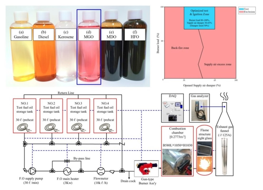
2.1. Design and Fabrication of Small Combustion Chamber

Because maritime fuel oil is primarily derived from low-quality fuel, it possesses high viscosity and high-temperature capabilities. As a result, a separate preheating apparatus and circulation system that is capable of heating diverse samples such as biodiesel and heavy oil were prepared for use in the study. In four different sites, four identical 30 L storage tanks that are capable of initially heating the temperature of the sample provided from the outside to a level of up to 100 °C or less were installed in different places. This helps to prevent mixing of sample components during the alternative fuel conversion test and precisely quantify the consumption flow rate. A bypass system, a gear pump, a 3 kW main heater that is capable of rapid heating to a temperature above 100 °C, and an electronic turbine flowmeter were also fitted to improve pipeline efficiency. The combustion chamber was built in a cylindrical shape with a capacity of less than 300 L; the actual capacity was approximately 277.3 L. The side door contained a gun-type burner that could be controlled by an inverter in accordance with the load. A high-temperature heat-resistant glass that could capture the picture properties of the flame was mounted on the opposite side. Several sensors for capturing data, such as temperature and pressure, were fitted in all areas, enabling DAQ transmission and real-time monitoring. Figure 1 depicts a schematic representation of the small combustion chamber system experiment. Table 1 outlines the key component specifications [25,26,27,28].

2.2. Combustion Sequence and Experiment Method

Figure 2 depicts an overview of the combustion sequence and experimental procedure. To remove the leftover gas within the chamber, ignition is attempted after undergoing a pre-purge procedure for around 40 s at a speed less than 3600 rpm, which corresponds to 100% load speed. When the ignition is turned on, the exhaust gas is monitored using a gas analyzer in a state where the inside of the combustion chamber has stabilized sufficiently. After the measurement period, the fuel valve is turned off and is finally halted by post-purge. In the case of a malfunction in the appropriate part, it is set to halt automatically and sound an alarm.
The gas analyzer for monitoring exhaust gas chosen was a T company model. The detailed specifications are included in Table 2 [29]. A thermocouple was used to simultaneously measure the oxygen concentration (%), CO2 concentration (%), NOx concentration (ppm), external temperature, and the exhaust gas temperature. The air ratio and dew point (°C) were both measured at the same time. To stabilize the measurement according to load changes, sufficient air purge and warming were performed after initial ignition. The average value of consecutive readings was then calculated for the cumulative data for 100 s.
Table 3 shows the operational settings for the experiment, which was carried out under a stable ambient environment and temperature. The humidity is 41.2%, while the temperature outside is in the range 8.8–10.6 °C. Weak combustion and rapid incomplete combustion occur in the low load range of the burner’s operational load. Thus, this process was implemented in three stages in the range 80–100% to ensure the experiment’s safety. The supply air damper was open 50% of the time, while the manual damper in the exhaust flue was open 100% of the time.
During the pilot test, the flame ignition stability fell dramatically from a burner load of around 60–70%, and the soot climbed rapidly. Further, the potential of ignition failure or backfire, which is produced by residual unburned oil stored inside the chamber, was deemed considerable. As a result, the optimal operating load was set at 10% in the 80–100% range considering ignition stability, and comparison measurements were only performed in three relevant areas. Figure 3 depicts the combustion optimization section, which considers account variations in the amount of supplied air and burner load, with the blue line indicating the optimal experimental area.

2.3. Material Properties of Marine Gas Oil

After activation of the fabricated device, MGO was chosen for the initial data collection for the most basic marine fuel oil emissions. To comply with environmental requirements, most small ships now utilize low-sulfur oil with a sulfur component less than or equal to 0.05% instead of high-sulfur oil. Because exhaust gas rules are gradually being tightened, MGO may become one of the most commonly utilized ship fuels in the future. MGO’s actual sulfur content in this study was approximately 0.0008%, which was adequate to meet the low-sulfur oil standard. It possesses almost identical physical attributes to high-quality unleaded diesel for land vehicles. However, to prevent improper distribution and mixing of regular diesel and marine fuel oil and to clearly distinguish users, the oil is transported in red color. Table 4 [30] lists the physical parameters of the selected MGO based on an investigation of its standard components. Figure 4 depicts a visual comparison of MGO, bunker oil for various ships, low-quality fuel, and the petroleum-based fuel used in this experiment.

3. Results and Discussion

3.1. Exhaust Gas Emission Characteristics

The oxygen content was 7.35% at 80%, which is the lowest load condition of this experiment, and increased by around 2.6% to 9.95% at 100% load. When the burner load changes, this can be seen as a difference in the amount of supplied air that is unnecessarily delivered according to the rotational speed of the draft fan. In the case of CO2, employing the operation control mode resulted in a maximum reduction effect of 1.91% from 10.07% at 80% load to 8.16% at 100% load. Figure 5, Figure 6 and Figure 7 show the emission characteristics by burner load in this small chamber.
Mostly, NOx emissions were significantly lower than 50 ppm overall, ranging from 50.92 ppm at 80% load to 31.95 ppm at 100% load. Even at low concentrations, NOx tended to decrease as the load increased. Unlike general combustion devices, this is a condition wherein the burner capacity of the matching device is greater than that of the chamber. Because an increase in the burner load results in an increase in the excess air ratio, the temperature of the exhaust gas is decreased, and the concentration reduces proportionally to the amount of dilution. This can be easily determined based on the properties of nitrogen oxides produced in a high-temperature zone. Nevertheless, because NOx is the actual value of the state in which the oxygen concentration changes during the measurement procedure, a quantitative comparison computation method is required [2,3,6]. Therefore, the standard oxygen concentration below 4% must be calculated by applying the oxygen concentration correction. This is due to the fact that the volume of exhaust gas provided and the amount of exhaust gas dilution vary according on the operating conditions.
Consequently, Equation (1) can be used to apply the same standard oxygen concentration of 4%. NOxactual measures nitrogen oxide, whereas O2ref uses 21% of the oxygen concentration in the environment. The standard oxygen concentration O2standard is 4%, while O2actual is the measured actual oxygen content. Figure 6 depicts the outcome of using the standard oxygen concentration. At 80% load, the NOx concentration was 63.44 ppm. However, at 100% load, the value was 49.13 ppm, indicating a decrease by 22.6% using the experimental settings.
N O x   p p m , 4 % = N O x a c t u a l × O 2 r e f O 2 s t a n d a r d O 2 r e f O 2 a c t u a l

3.2. Exhaust Gas Temperature Characteristics

During the experiment, the average ambient air temperature was in the range 8.8–10.6 °C. However, some temperatures rose throughout the preheating procedure of the laboratory chambers, and thus, the actual measured supply air temperature was in the range 17.2–21.7 °C. Figure 8 depicts the supply and exhaust gas temperatures. According to the load fluctuation of the burner, the exhaust gas temperature is 614.9 °C in the low load range of 80%, while at 100%, which is the maximum load, the temperature was 549.2 °C. The temperature difference due to load change was approximately 65.7 °C. This demonstrates that as the load increases, the amount of supplied air delivered also increases, and the temperature drops. As a result, it is clear that the exhaust gas temperature is relatively greater in the low load region. The constructed experimental device is a fixed value condition wherein the actuator proportional control mode, which allows optimal combustion tracking based on the amount of supplied air, is not used. As a result, the experimental arrangement has a few limitations. Thus, we intend to undertake more extensive tests in the future by establishing conditions for proportional control. The dew point is depicted in Figure 9. Corrosion may occur on the metal body if the exhaust temperature is kept below the dew point [31]. Having said that, in this experimental environment, it remains constant in the range 41.8–44.9 °C, indicating that the exhaust gas temperature is sufficiently greater than the dew point during ignition. However, corrosion may develop as the temperature of the combustion chamber surface or the surface temperature of other metals rises over the dew point in case of long preheating [32]. Thus, this factor must be sufficiently considered during operation.

3.3. Combustion Efficiency

The combustion efficiency was calculated using Equations (2) and (3) and according to the exhaust gas test results. The combustion loss rate is denoted by qA, exhaust gas temperature by FT, and the supply air temperature by AT. Here, A2 is a unique parameter for each fuel offered by the brand. The dimensionless constant associated with MGO is 0.686, while B1 is 0.007 [33]. Further, O2ref is 21%, and Kk is a correction constant when the exhaust gas temperature is lower than the dew point. Figure 10 shows the final calculation of Effc (%) from the induced combustion loss rate qA. It was in the range 66.94–70.17% under this experiment condition. As the load increased, it tended to drop by up to 3.23%, with 80% load being the most optimal working condition.
q A = F T A T × A 2 O 2 r e f O 2 + B 1 K k
E f f c   % = 100 q A

4. Conclusions

A small combustion chamber with a capacity less than 300 L was designed and fabricated in this study. An MGO with a sulfur content less than 0.05% was burned and tested. The findings of the study are summarized below:
  • When the load of the burner installed in the combustion chamber was set to 80–100%, ignition stability was ensured, and the backfire of residual oil was prevented, thus confirming the load range as optimal.
  • The CO2 level was in the range 8.16–10.07% within the experimental conditions, and there was a maximum reduction effect of 1.91% through load control.
  • The NOx content was in the range 49.13–63.44 ppm when a standard oxygen concentration of 4% was applied from the actually measured initial value. Thus, a maximum reduction of 22.6% was possible.
  • The exhaust gas temperature was in the range 549.2–614.9 °C, with a difference of approximately 10.7%. Because the exhaust gas is formed at a high temperature, it is necessary to reduce the capacity of the burner to a value below the designed chamber capacity.
  • The combustion efficiency was at the level of 66.94–70.17% in this experimental condition, and it was the highest at the burner load of 80%.

Author Contributions

Conceptualization, T.-H.L.; methodology, I.-S.K.; software, T.-H.L.; validation, T.-H.L.; formal analysis, T.-H.L. and I.-S.K.; investigation, T.-H.L.; resources, I.-S.K.; data curation I.-S.K.; writing—original draft preparation, T.-H.L.; writing—review and editing, T.-H.L. and I.-S.K.; visualization, T.-H.L.; supervision, I.-S.K.; project administration, T.-H.L.; funding acquisition, T.-H.L. and I.-S.K. All authors have read and agreed to the published version of the manuscript.

Funding

This work was supported by development fund foundation, Gyeongsang National University, 2022.

Institutional Review Board Statement

Not applicable.

Informed Consent Statement

Not applicable.

Data Availability Statement

Not applicable.

Conflicts of Interest

The authors declare no conflict of interest.

Abbreviations

MGOmarine gas oil
O2oxygen
O2refoxygen concentration reference by fuel
O2standardstandard oxygen concentration
NOxnitrogen oxide
NOxactualnitrogen oxide actual value
SO2sulfur dioxide
CO2carbon dioxide
qAcombustion loss ratio
FTexhaust gas temperature
ATsupply air temperature
A2fuel parameter
B1correction factor
Kkdew point reference value
Effccombustion efficiency

References

  1. Nicole, J.F. World Energy Outlook 2018; IEA Publications: Paris, France, 2018. [Google Scholar]
  2. Lee, T.H.; Lee, S.H.; Lee, J.K. Exhaust gas emission improvements of water/bunker C oil-emulsified fuel applied to marine boiler. J. Mar. Sci. Eng. 2021, 9, 477. [Google Scholar] [CrossRef]
  3. Lee, T.H. A Study on the Characteristics of Exhaust Emissions in a Marine Boiler Using Emulsified Bunker-C Oil; Jeonbuk National University: Jeonju, Republic of Korea, 2020. [Google Scholar]
  4. OPEC. OPEC Annual Statistical Bulletin; Organization of the Petroleum Exporting Countries: Vienna, Austria, 2017. [Google Scholar]
  5. Lee, T.H.; Cho, J.H.; Lee, J.K. Mixing properties of emulsified fuel oil from mixing marine bunker-C fuel oil and water. J. Mar. Sci. Eng. 2022, 10, 1060. [Google Scholar] [CrossRef]
  6. Lee, T.H.; Lee, J.K. An Experimental Study on the NOx Reduction of Emulsified Oil Applied to Boiler-Burner Using Bunker C Oil. J. Korean Soc. Mech. Technol. 2019, 21, 1071–1076. [Google Scholar] [CrossRef]
  7. Lee, T.H.; Lee, J.K. An experimental Study on the SO2 reduction of water 10% mixed emulsified oil applied to boiler-burner using bunker-C Oil. Sci. Educ. 2019, 31, 1801–1807. [Google Scholar] [CrossRef]
  8. IMO. Prevention of Air Pollution from Ships: Reducing Shipping Emissions of Air Pollution-Feasible and Cost-Effective Options; MEPC: London, UK, 2005; p. 53/4/1. [Google Scholar]
  9. Doh, H.J.; Lee, S.Y. A Study on the IMO environmental regulations and economic feasibility of bunkering options. J. Marit. Bus. 2021, 49, 73–97. [Google Scholar]
  10. Lee, T.H.; Ryu, Y.H. Viscosity characteristic analysis of coffee ground oil for marine fuel applications. J. Korean Soc. Mech. Technol. 2021, 23, 892–897. [Google Scholar] [CrossRef]
  11. IMO. Fourth IMO Greenhouse Gas Study; IMO: London, UK, 2020. [Google Scholar]
  12. IMO. Amendments to the ANNEX of the Protocol of 1997 to Amend the International Convention for the Prevention of Pollution from Ships 1973 as Modified by the Protocol of 1978 Relating Thereto; IMO MEPC 62/24/Add.1; IMO: London, UK, 2011. [Google Scholar]
  13. Lee, T.H.; Ryu, Y.H. A Study on mixing properties of coffee ground-fuel for improvement of air pollution from ships. J. Korean Soc. Mech. Technol. 2021, 23, 181–186. [Google Scholar] [CrossRef]
  14. Ryu, Y.H.; Dan, T. Investigation on the effects of dimethyl ether blending to bunker oil for marine diesel engine use. SAE Tech. Pap. 2013. [CrossRef]
  15. Yoon, J.H.; Yeom, J.K. Numerical analysis on behavior characteristics of evaporative spray of emulsified fuel impinging on a heated flat plate. Trans. KSME-B 2019, 43, 471–477. [Google Scholar] [CrossRef]
  16. Kim, S.R.; Lee, J.S. The development and performance test of a Small Wood boiler. Trans. KSME-B 2002, 26, 491–497. [Google Scholar] [CrossRef]
  17. Song, D.B.; Lim, K.H.; Jung, D.H. Development of heated-air dryer for agricultural waste using waste heat of incineration plant. J. Agirc Life Sci. 2019, 53, 137–143. [Google Scholar] [CrossRef]
  18. Kim, H.S.; Jang, D.S.; Lee, J.G.; Shin, M.S.; Choi, Y.C. A numerical Study on combustion characteristics of Orimulsion fuel in a small-scale combustor. J. Korean Soc. Environ. Eng. 2004, 26, 494–500. [Google Scholar] [CrossRef]
  19. Kim, H.S.; Shin, M.S.; Lee, J.G.; Jang, D.S.; Choi, Y.C. Study on the combustion characteristics of a small-scale Orimulsion boiler. J. Korean Soc. Environ. Eng. 2005, 27, 1081–1089. [Google Scholar]
  20. Oh, J.S.; Kang, S.B.; Lee, H.H.; Choi, K.S. Comparative Study on pyrolysis characteristics between wood and rice pellets for the universal use of a rice pellet boiler. Trans. KSME-C. 2020, 8, 71–76. [Google Scholar] [CrossRef]
  21. Lee, H.D.; Cho, S.H.; Yoon, H.J.; Yoon, S.W. Design of heating system and evaluation of environmental test using eco-friendly bio-fuel. KSFM J. Fluid Mach. 2023, 26, 29–39. [Google Scholar] [CrossRef]
  22. Kim, K.H. Study of spatial temperature distribution during combustion process in a high temperature and pressure constant volume chamber. J. Korea Acad.-Ind. Coop. Soc. 2017, 18, 345–350. [Google Scholar] [CrossRef]
  23. Lim, B.J.; Lee, J.S.; Lee, K.J.; Park, J.S. A mixing head integrated, multi-ignition device for liquid methane engine. KSPE 2022, 26, 54–65. [Google Scholar] [CrossRef]
  24. Chung, J.D. An Experimental Study on the Combustion Characteristics of Wastewater-Emulsified fuel. J. Energy Eng. 2003, 12, 267–273. [Google Scholar]
  25. SHINIL. Instruction Manual on Industrial Incinerators SL-130; SHINIL Metal Co., Ltd.: Inchon, Republic of Korea, 2022. [Google Scholar]
  26. Seung-Hwa Industry. Gas and Oil Hinge Burner Specification and Dimension; Seung-Hwa Co., Ltd.: Daegu, Republic of Korea, 2016. [Google Scholar]
  27. Danfoss. Facts Worth Knowing about Oil Nozzles 520F0019; Danfoss G1 Advertising Agency: Nordborg, Denmark, 2016. [Google Scholar]
  28. Danfoss. Data Sheet of Oil Nozzle Type No. 030H6920; Danfoss Co., Ltd.: Nordborg, Denmark, 2016. [Google Scholar]
  29. Park, S.B. Calibration Report of Gas Analyzer for TESTO-340 (No. 61799065); Testo Korea Co., Ltd.: Seoul, Republic of Korea, 2019. [Google Scholar]
  30. Hwang, K.W. Refined Oil Product Quality Assurance of 500 ppm Marine Gas Oil No. RL22120610553; GS Caltex Co., Ltd.: Seoul, Republic of Korea, 2022. [Google Scholar]
  31. Choi, J.H.; Lee, S.J. Analysis of dew point and corrosion resistance for power plant economizer tube with exhaust gas temperature and sulfuric acid concentration. Surf. Sci. Eng. 2022, 55, 433–440. [Google Scholar] [CrossRef]
  32. Wang, Y.G.; Zhao, Q.X.; Zhang, Z.X.; Zhang, Z.C.; Tao, W.Q. Mechanism research on coupling effect between dew point corrosion and ash deposition. Appl. Therm. Eng. 2013, 54, 102–110. [Google Scholar] [CrossRef]
  33. TESTO. Flue Gas Analyzer Instruction Manual on Testo-340; Testo Co., Ltd.: West Chester, PA, USA, 2016. [Google Scholar]
Figure 1. Experiment Schematic of Small Combustion Chamber.
Jmse 11 00609 g001
Figure 2. Combustion sequence and measurement section.
Jmse 11 00609 g002
Figure 3. Optimal testing range of small combustion chamber.
Jmse 11 00609 g003
Figure 4. Comparison of marine fuel oil samples: (a) gasoline oil, (b) diesel oil, (c) kerosene, (d) marine gas oil, (e) marine diesel oil (bunker-a), (f) heavy fuel oil (bunker-c).
Jmse 11 00609 g004
Figure 5. Comparison of carbon dioxide according and oxygen content.
Jmse 11 00609 g005
Figure 6. Comparison of nitrogen oxides using standard oxygen concentration of 4%.
Jmse 11 00609 g006
Figure 7. Comparison of excess air ratio.
Jmse 11 00609 g007
Figure 8. Comparison of supply air and exhaust gas temperature.
Jmse 11 00609 g008
Figure 9. Comparison of dew point.
Jmse 11 00609 g009
Figure 10. Comparison of combustion efficiency.
Jmse 11 00609 g010
Table 1. Specifications of combustion chamber and components.
ItemListSpecificationUnit
Combustion chamberTypetransverse cylinder-
Volume277.3L
Size∅580 × L1050 × H1030mm
Thickness2.3–4.0mm
Sight glassmax. 600°C
Funnel∅125mm
Weight926.73N
Burner assemblyTypegun-type-
Calorific capacity37,000–99,000kcal/h
Consumptionmax. 10.0kg/h
Fan motor0.11kWh
ControlOn–Off-
NozzleModel030H6920-
Flow rate3.72 (1.0)kg/h (US gal/h)
Injection angle60°
Sprayinghollow cone-
Definition point10.0bar
Weight0.294N
Table 2. Specifications of the exhaust gas analyzer.
ParameterRangeUnitResolutionError
O20–25vol, %0.01±0.2
CO20–CO2maxvol, %0.1±0.2
NOx0–4000ppm1±5.0
Temperature−40–1200°C0.1±0.5
Table 3. Detailed experimental conditions.
ListSpecificationUnit
TemperatureOutside 8.8–10.6°C
Fuel 10.1–10.4
Humidity41.2%
Atmospheric oxygen21.0%
Burner assembly load80–100%
Fuel oil flow rate3.68L/h
Nozzle injection pressure10.45kg/cm2
Opened and fixed the damperInlet 50%
Outlet 100
Table 4. Properties of marine gas oil material.
ListTest MethodQuality StandardResult
API Gravity (@ 60 °F)ASTM D 1298-36.6
Sulfur content (m/m, %)ASTM D 54530.050.0008
Flashpoint (°C)ASTM D 934066.0
Density (@ 15 °C, kg/L)ASTM D 4052-0.8415
ColorColor visualredred
Disclaimer/Publisher’s Note: The statements, opinions and data contained in all publications are solely those of the individual author(s) and contributor(s) and not of MDPI and/or the editor(s). MDPI and/or the editor(s) disclaim responsibility for any injury to people or property resulting from any ideas, methods, instructions or products referred to in the content.

