Article

Development of a Cascade Intelligent System for Path Planning of the Group of Marine Robotic Complexes

1
Institute of Hydrodynamics and Control Processes, Saint-Petersburg State Marine Technical University, Lotsmanskaya St., 3, 190121 Saint-Petersburg, Russia
2
Research and Development Department, Saint-Petersburg State Marine Technical University, Lotsmanskaya St., 3, 190121 Saint-Petersburg, Russia
3
Department of Applied Mathematics and Mathematical Modelling, Saint-Petersburg State Marine Technical University, Lotsmanskaya St., 3, 190121 Saint-Petersburg, Russia
4
Department of Educational, Scientific and Technical Activities of the Ministry of Emergency Situations of Russia, Davydkovskaya St., 7, 121352 Moscow, Russia
5
DST URAL, Geroev Tankograda, 28p, 454081 Chelyabinsk, Russia
6
Institute of Engineering and Technology, South Ural State University, Lenin Av., 76, 454080 Chelyabinsk, Russia
7
Department of Drive Systems, Mechatronics and Robotics, Baltic State Technical University, St. 1st Krasnoarmeyskaya, 1, 190005 Saint-Petersburg, Russia
*
Authors to whom correspondence should be addressed.
J. Mar. Sci. Eng. 2023, 11(3), 610; https://doi.org/10.3390/jmse11030610
Submission received: 18 December 2022 / Revised: 9 March 2023 / Accepted: 11 March 2023 / Published: 13 March 2023
(This article belongs to the Special Issue Advances in Marine Vehicles, Automation and Robotics)

Abstract

:
Artificial Intelligence (hereinafter referred to as AI) systems have recently found great application and use in various industries, such as data processing, data analysis, and the operation control of marine robotic complexes, etc. In view of the ever-increasing degree of complexity of the missions assigned to marine robotic systems, it is becoming obvious that the AI technologies should be used as combined systems which can provide control of marine robotic complexes (hereinafter referred to as MRCs), their navigation in sea, logic formation of MRC behaviour in uncertain environments, path planning, and processing optimization of the received MRC payload data. All the areas mentioned above are within the field of MRC development, and currently do not have a general solution. This article discusses the development process of an intelligent system for path planning of a group of marine robotic complexes. The architecture of the intelligent system is based on a cascade approach, which includes the consistent use of functional modules designed as various “organs of perception” of the system. A detailed description of the development of each module and mathematical modelling of the presented algorithms are provided in this paper, and the main results of the conducted full-scale experiments are demonstrated.

1. Introduction

Currently, intelligent systems (hereinafter referred to as ISs) have a very wide range of applications thanks to AI development that extend human skills and capabilities.
The term “Artificial intelligence” is widely used at present to refer to applications for complex missions that previously could only be performed by humans. AI makes it possible to reproduce and improve on what we learn from the world around us and what can be done with such information. This feature of AI underlies innovation. AI is based on various machine learning technologies, which recognize data patterns and generate predictions. In view of this particular feature, AI is an intermediate link that often lies at the junction of several technologies, which allows the potential of various systems to be increased and the best results to be achieved more effectively.
Today, AI technologies, machine learning (hereinafter referred to as ML), and deep learning (hereinafter referred to as DL) technologies are used in the field of marine robotics. Developers increasingly use these methods to implement planning, control, and internal diagnostic systems in the field of airborne [1,2], ground [3,4], and marine robotic complexes [5,6,7], including underwater gliders [8,9,10] and surface gliders [11], as well as for the tasks of monitoring and patrolling potentially dangerous underwater objects. Intelligent systems provide the implementation of adaptation to uncertain environments [12,13] and ability to evaluate and simulate the current state [14,15,16], and can perform goal-setting functions and action planning for air, ground, and sea robotics [17,18,19,20], including vehicle basing (issues related to AUV docking) [21].
Currently, a transition is underway from group control to practical implementation of group applications for homogeneous groups of autonomous vehicles (hereinafter referred to as AVs) [22,23,24] and heterogeneous groups of AVs [25,26]. Developers use existing groundwork from video games to train neural networks in order to set up and train multi-agent teams [27,28,29,30,31,32,33]. Progressive development of models and technologies for group application of marine robotic complexes (and MRCs as well) poses new challenges for developers related to the planning and operation of MRC groups in uncertain marine environments [34,35]. Marine robotics usually involves performing tasks without preliminary detailed mapping in large open water areas with different depths, bottom topography, and constantly changing periodic and aperiodic effects. In addition, the underwater environment imposes significant restrictions on the possibility of using the sensor, communication, and navigation systems of AVs, leading to additional requirements to consider the power and structural features of the controlled object as well as the conditions of the area for the planned job. To take into account such functional features, developers often use methods based on intelligent neural networks and ML, which makes it possible to increase the autonomy of the MRC. In previous papers [36,37,38,39], authors have demonstrated the use of neural networks to solve the problems of positioning and navigation of MRC as well as to calibrate the automatic control system [40,41,42,43,44,45,46].
Analysis has shown that while AI systems are widely used to solve data analysis and processing problems [47,48,49,50,51,52,53,54,55,56,57], they are generally not used in motion-planning systems for groups of AVs. To date, there have been papers presenting the use of AI for motion planning of a single marine robotic complex [58,59] and as an auxiliary decision-making system when objects move in sophisticated environments with obstacles [60,61,62,63,64]. However, these papers do not consider features of the interaction of AVs with each other or features of group operation when moving in a formation, when it is necessary to solve the tasks of rebuilding or reconfiguring the formation. It should be noted that developers are currently considering centralized principles in this direction to build up a group management system. Such systems have a distinctive feature in the relatively low “survivability” of the system in case of unforeseen situations (e.g., failure of the leader). Moreover, assumptions are made upon MRC operation taking the preliminary cartography into account.
In this paper, we have taken up the task of developing an intelligent system for governing group interaction of MRCs. The proposed system should analyze data available to the group, make a recommendation as to the next action taken by each agent, and form an intragroup interaction policy. This allows the system to conduct subsequent self-learning in order to find adaptive solutions and ways to rebuild and reconfigure the formation in the most optimal way. A key distinguishing feature of intelligent MRC operation with an adaptive control and planning system is that the sequence of actions necessary to achieve the goal is not determined in advance, as information on future states of the environment is generally not available. The advantage of the developed “cascade” planning method over other group motion planning systems is the use of DL methods for each agent to ensure that the decentralized control concept is complied with. The developed “cascade” method of group motion planning has a modular architecture for easy system scaling. The presented method combines various algorithms for different tasks, for instance, to form a group interaction area, process group sensory data, and combine reinforcement learning methods for intra-group interaction of MRCs.
Today, reinforcement learning methods are widely used in motion planning systems for robots and groups of robots [65,66,67,68]. However, the results of related studies and papers have mostly described the use of Artificial Neural Networks in certain deterministic conditions with known hard-coded values for the area of operation. These sources present the use of centralized AI systems for the optimal distribution of a group of robots over an area and the organization of group interaction to solve a global task in front of a group, for example, using the smart factory pattern implementation [69]. In particular, many methods are based on the analysis of information obtained from preliminary cartography, which is not available in real conditions in general. Our analysis revealed that currently available methods and algorithms cannot explicitly solve the problems of monitoring, patrolling, and surveillance of the required territories and objects, which include, for example, potentially dangerous underwater objects. Thus, it is necessary to consider reconfiguration and adaptive changes to address the presence of such objects within the structure of the formation while avoiding both static and moving obstacles. A new algorithm based on graph-analytical and neural network methods is presented in our study. The combination of reinforcement learning and graph-based algorithms is advantageous, as it allows robotic complexes and group(s) to quickly identify possible research areas and use their knowledge to maximize rewards. For example, graph-based algorithms can calculate the global situation and trajectory as well as the future states of each individual robot or group (which may lead to high rewards) and the best ways to change the state. Reinforcement learning can use this information to realize improve performance.
In this article, Section 2 considers the formal statement of the problem and the problems associated with the use of the MRC groups in uncertain environments with obstacles. This section provides a workflow for developing the intragroup MRC interaction algorithms. Next, Section 3 proposes the development workflow of a neural network cascade system for path planning of an MRC group, including the development workflow for its architecture. Our full-scale experiment is described in detail in Section 4. Finally, in the conclusion we summarize the key results of this research and propose future work for the development of MRC group path-planning intelligent systems.

2. Problem Statement

The primary goal of the present study is to develop a neural network system for path planning of the MRC group that allows agents to move in an uncertain environment with fixed and moving obstacles while taking into account the restrictions imposed on maintaining the structure of the MRC group formation.
The following tasks must be resolved in order to implement the cascade system of intelligent path planning of the MRC group:
  • Development of algorithms for the local path planner of each agent in the group and the global approach of the group motion;
  • Implementation of the logical approach for the intragroup policy operation for the interaction of agents in a group, which is based on the communication range and the vision system parameters, which in turn are functions of the current and predicted parameters that describe environmental conditions, including data on the location of agents and their current state;
  • Development of an architecture for the intelligent interaction of agents based on the existing intragroup policy.
The general structure of the proposed cascade approach for the intelligent interaction planning of the MRC group in an uncertain environment with obstacles is presented in the Figure 1.
The figure shows the following main stages of the intelligent planning system operation:
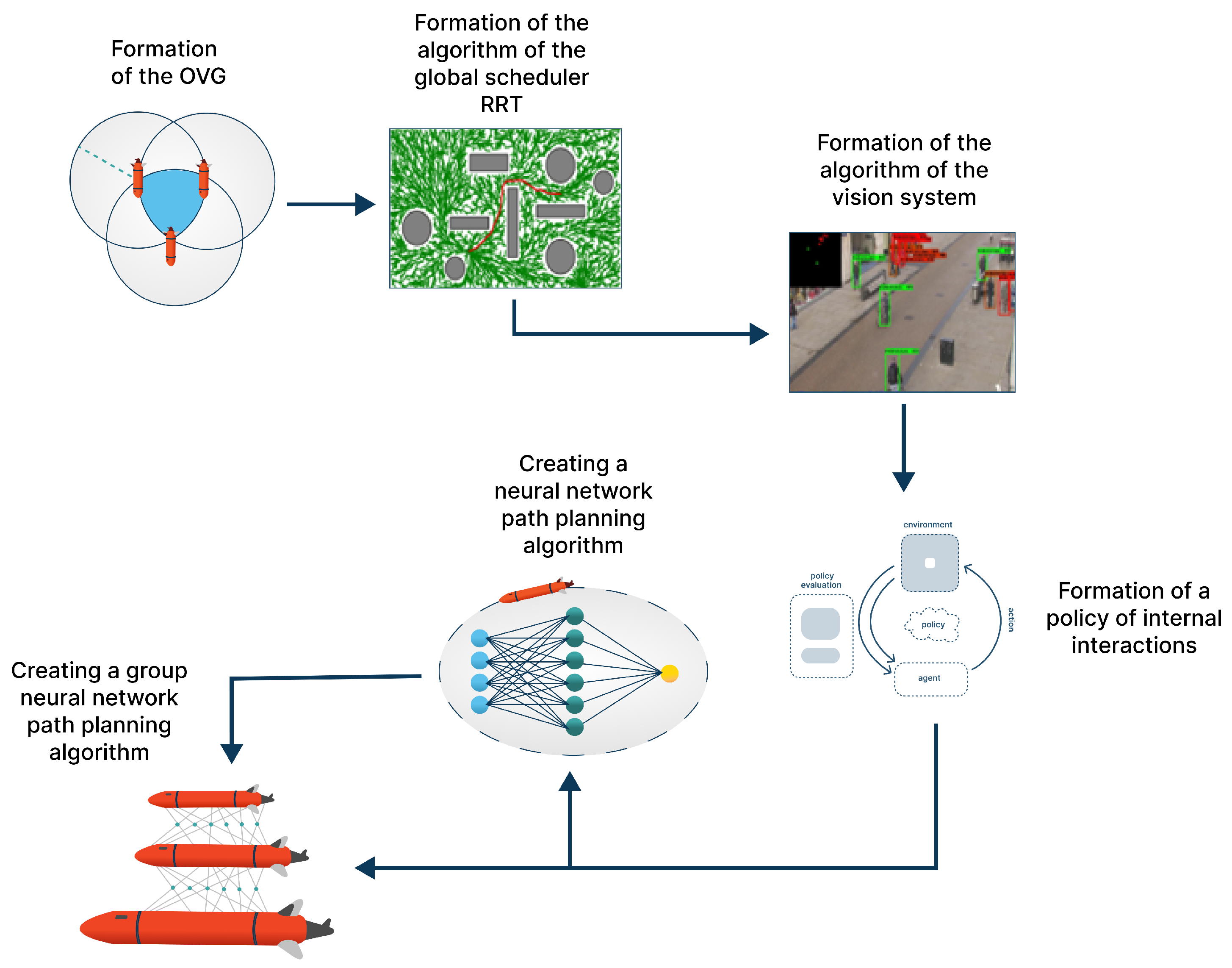
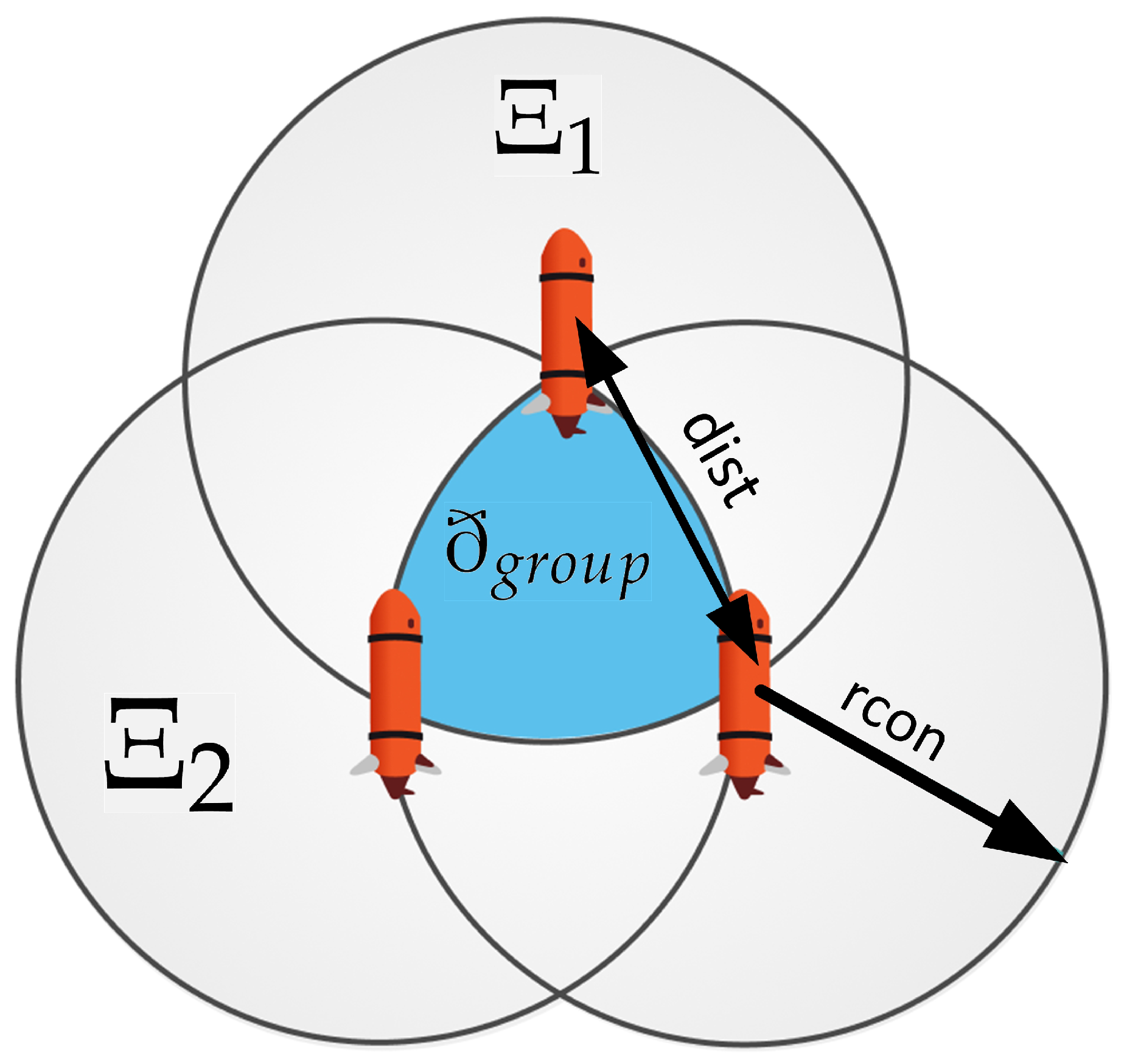
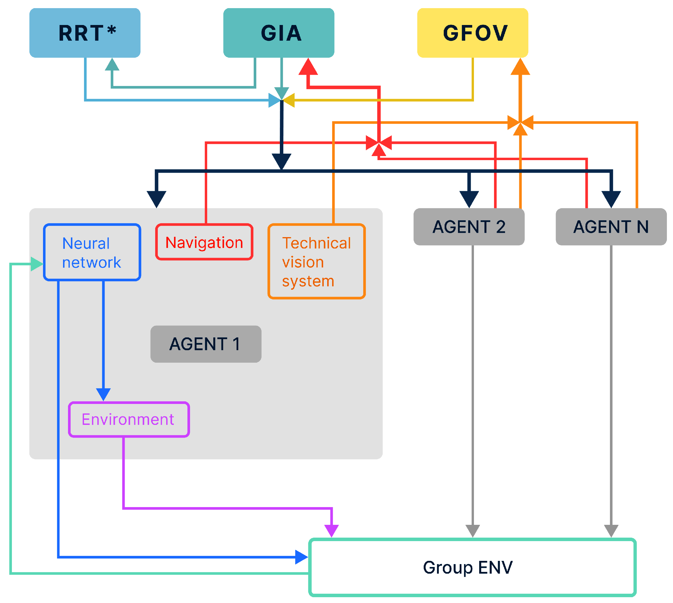
  • Formation of an area of group interaction ð g r o u p . This module implements the construction of the area space, in which all agents of the group must be located.
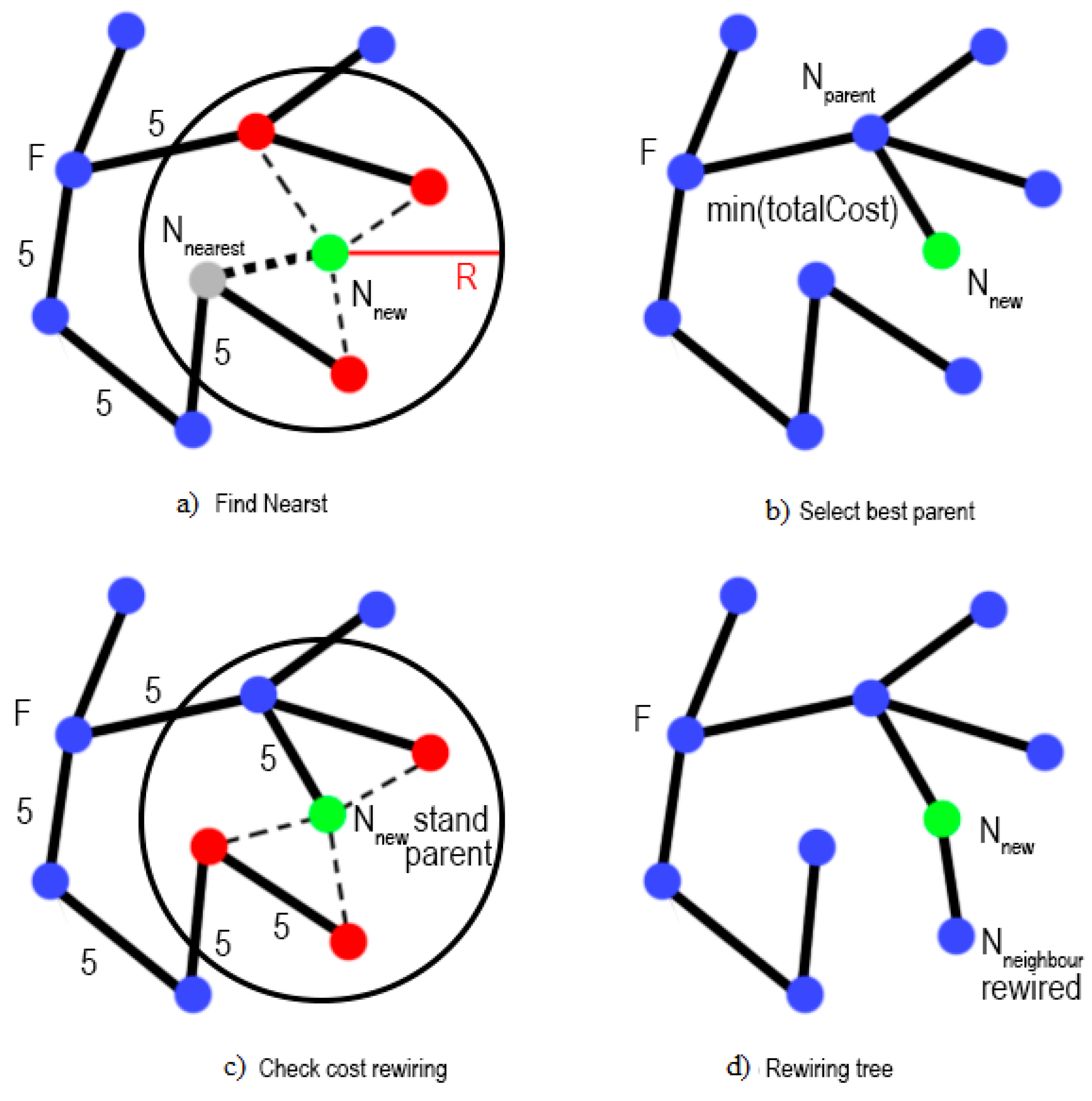
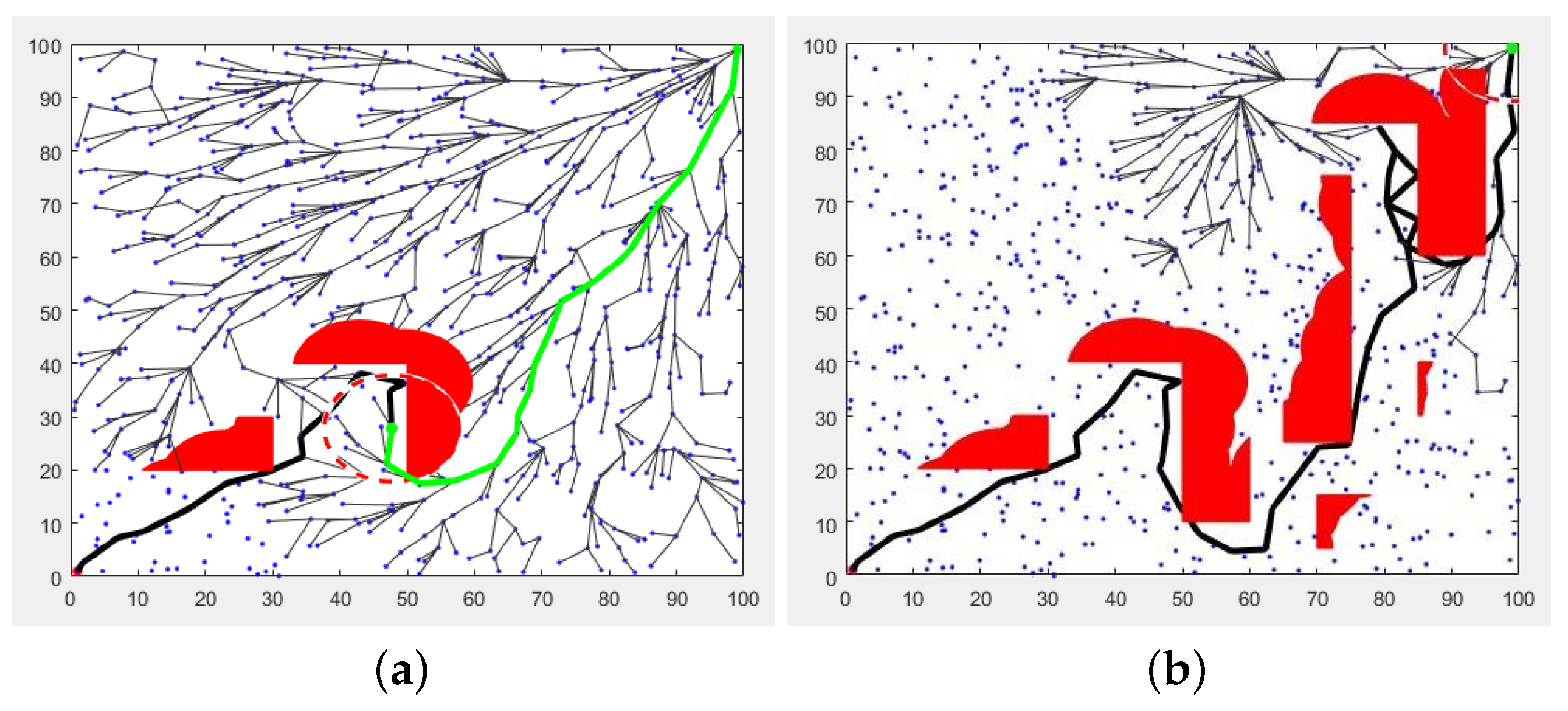
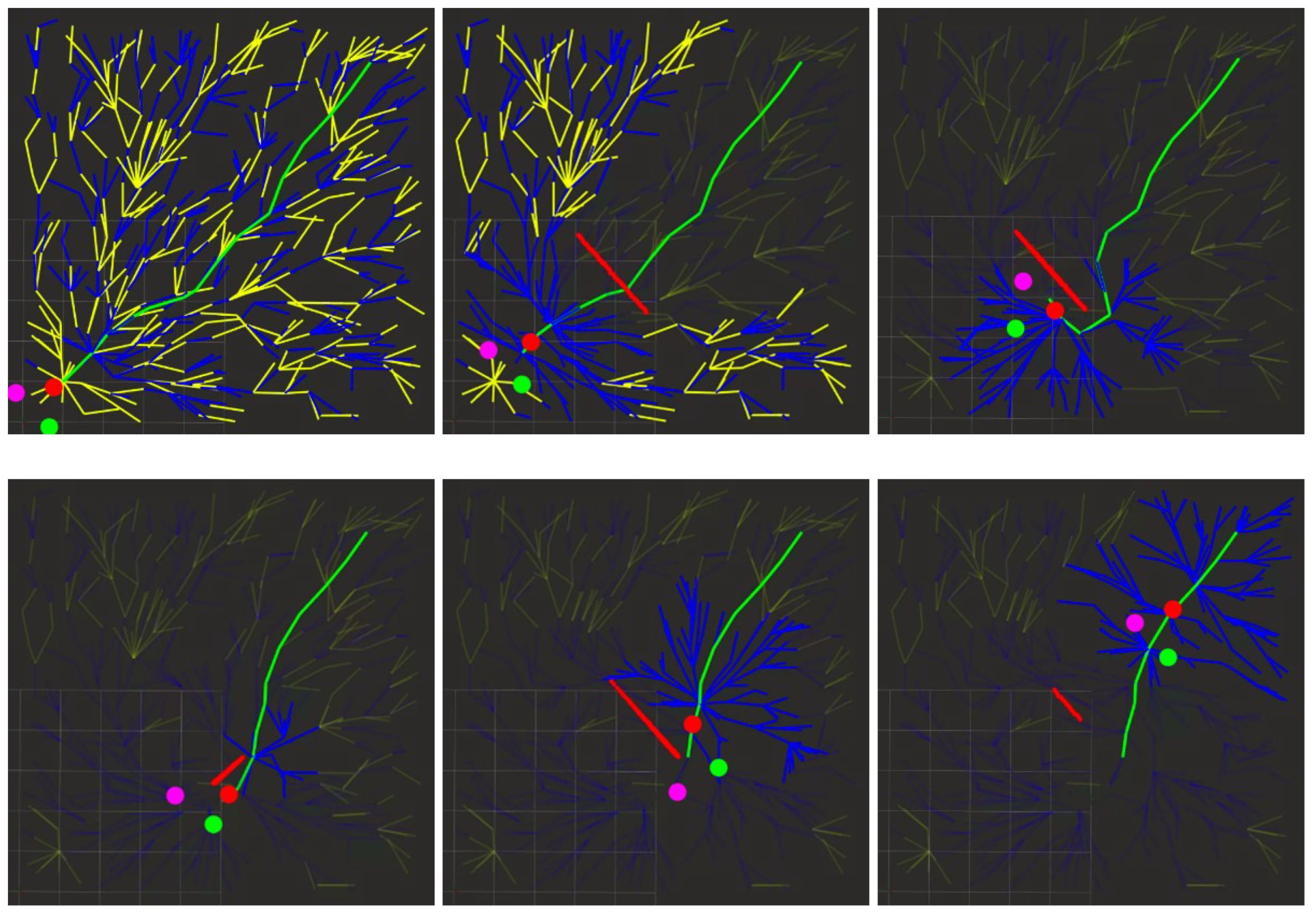
  • Global planning algorithm development based on the RRT* method. This algorithm provides real-time trajectory formation of the group H g r o u p without preliminary area mapping.
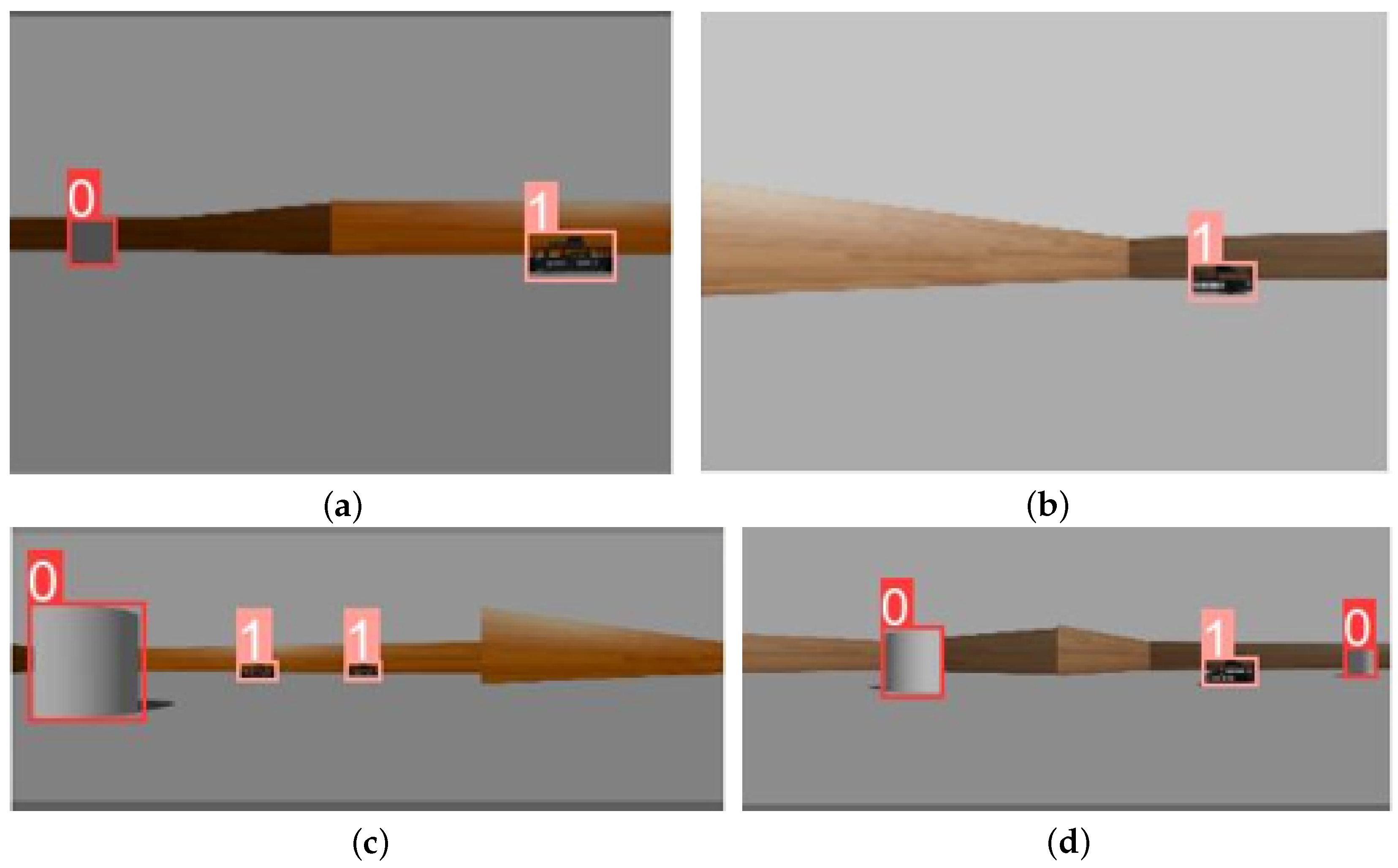
  • Vision system (hereinafter referred to as VS) of each agent in the group, which forms a dataset Ω n of the existing obstacles in the AV’s n field of view. This algorithm integrates the data received from the VS of each AV into a single field of view Ω g r o u p ( R 1 , R 2 , R 3 ) (in which case n = 3 ), which provides the subsequent analysis and a recommendation at the next stage of the planning algorithm operation.
  • Formation of a policy for the internal interaction of agents in a group P a g e n t s . This module is required for the analysis of all events occurring in the external space around the agent E a and its reaction to these events A n based on conditions that determine the current state of other agents in the group S a g e n t s ( S a 1 , S a 2 ) , taking the group task into account.
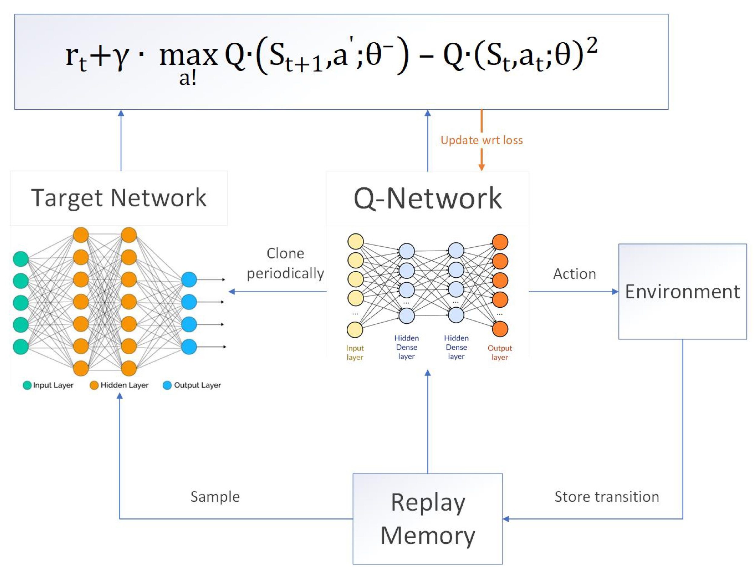
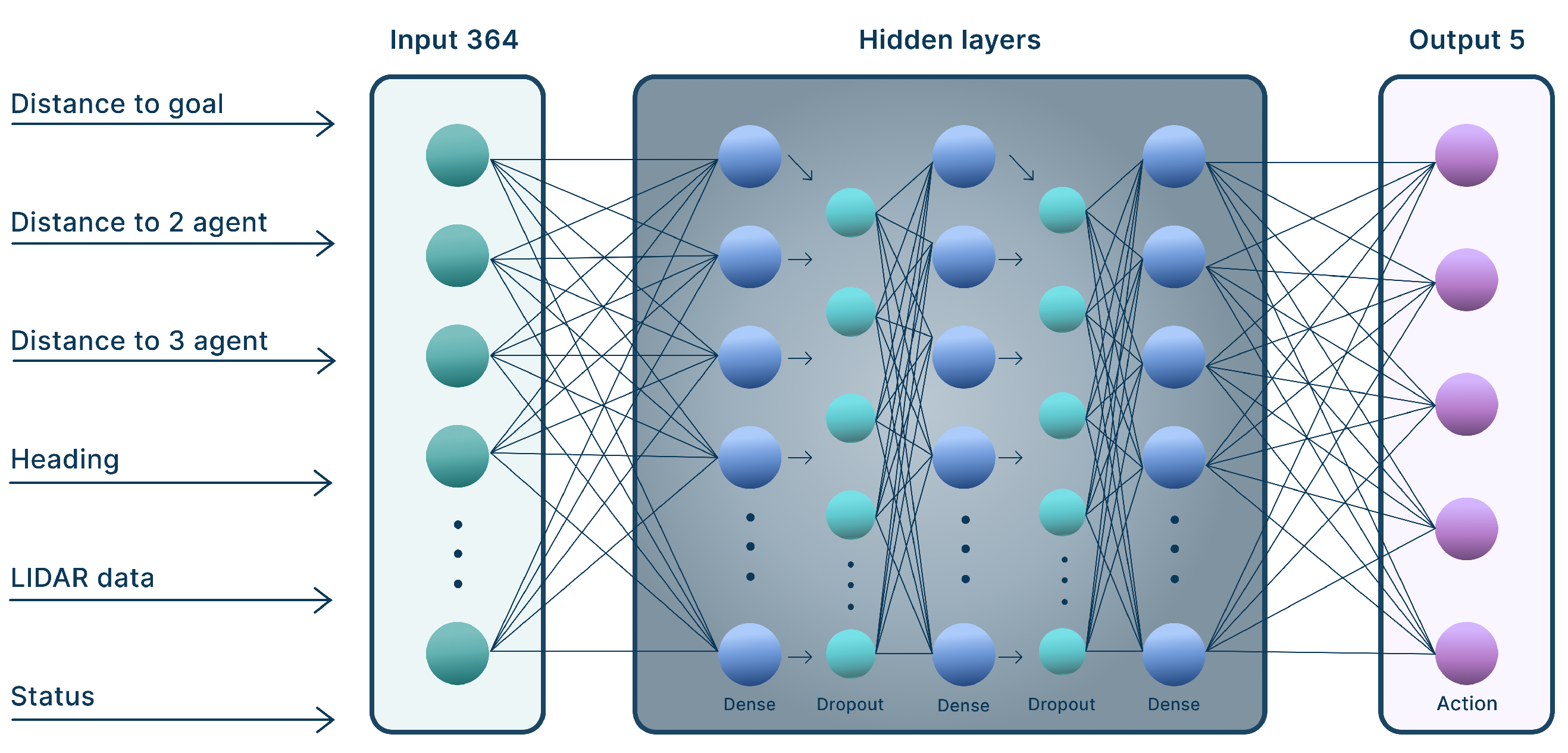
  • Development of a neural network path planner for each agent in the group, which manages the local trajectory of the agent’s motion and is based on the data received from the built-in VS systems. In addition, this manages the agent’s position in the group interaction area (hereinafter referred to as GIA) and the group interaction policy parameter. This method is based on the DQN approach [61,70] with a modernized error function.
  • Development of a group neural network planner, which is aimed at ensuring the synergy of data received from each agent’s individual neural network. This module calculates the group reward policy R g r o u p , and affects the subsequent actions of each agent in the group.

2.1. Development of the GIA Formation Algorithm

Use of MRC groups in real sea conditions is always associated with the use of high-precision technologies to ensure proper positioning and the necessary parameters for radio and hydroacoustic communication. However, it is not always possible for developers to take into consideration the various indicators of marine environment stratification, the presence of multidirectional currents, and other non-stationary processes, especially when the MRC is used in 3D marine environments [71,72,73]. An aspiration to ensure high accuracy in the field of MRC groups’ application leads to the high complexity of algorithm development in this context, and, on the other hand, to the high complexity of implementation and application in real-world conditions [27,34,74]. Therefore, we have decided to deviate from the generally accepted principles of constructing a “hard-coded system” of the MRC formation and implement a method for constructing an MRC group based on the GIA. This method can be described by the following set of parameters (under the conditions of applying the algorithm in a 2D formulation): d i s t r —given distance between agents; r c o n —range of the communication system (e.g., radio communication systems during the MRC surface group operation). To calculate the boundaries of the GIA ð g r o u p , the following expression is used (1):
ð 1 = Ξ 1 Ξ 2 ð 2 = ð 1 Ξ 3 ð g r o u p = ð 1 ð 2
where Ξ 1 ( r c o n 1 , d i s t r ) ,   Ξ 2 ( r c o n 2 , d i s t r ) ,   Ξ 3 ( r c o n 3 , d i s t r ) are the bounding areas of operation for each agent of the group depending on the distance between agents and the allowable communication range. An example of the formation of the GIA is shown in Figure 2.
Output values after the algorithm operation are the variables [ R , E d i s t , E c o n ] ð g r o u p describing the states between all agents in group (2) and the group’s estimated center ð g r o u p :
E d i s t = | R 1 R 2 | d i s t r | R 1 R 3 | d i s t r | R 2 R 3 | d i s t r E c o n = r c o n | R 1 R 2 | r c o n | R 1 R 3 | r c o n | R 2 R 3 |
This set of parameters is used for subsequent training of the group neural network, which is responsible for analysis and recommending further actions, either as a single agent in the group or the entire group.

2.2. Development of an Algorithm for the MRC Group’s Global Trajectory Planning

The designed system for the global planning trajectory formation is based on the real-time RRT* method. The primary task of the MRC group is to move from the starting point to the end point. To do this, we propose building up a map of random tree branches to cover the entire considered area. This process does not take very much time, and can be performed during the pre-launch phase.
The following input parameters are used: R is the functioning area’s size; S p is a starting point of the group; F p is an end point of the group; ε is a simulation step; r r is a coefficient describing the radius within which the search for neighbouring nodes of the tree is performed. All calculated points are saved to the array T ( i ) = ( t 1 , t 2 ) of i × 2 dimension, where i is the number of algorithm iterations.
During each iteration, we take a random point from R a n d p = N n e w 1 , N n e w 2 , , which is a random sequence. The distance from N n e w to all other points in the tree is calculated and an array D = ( D i s t , i d ) is formed, where D i s t is the distance and i d is the number of points in the tree of i 2 dimension with i being the number of algorithm iterations (3).
D i s t = ( n 1 t 1 ( i ) ) 2 + ( n 2 t 2 ( i ) ) 2 2
The closest point to N n e w is selected, i.e., N n e a r = m i n ( D ) . Thus, N n e w moves closer to the selected point, meaning that N n e w is epsilon away from the selected point (4).
N n e w ( 1 ) = t 1 + ( 1 ) e ( t 1 n 1 ) / D i s t N n e w ( 2 ) = t 2 + ( 1 ) e ( t 2 n 2 ) / D i s t
Next, points located within the circle of radius r and its the center in N n e w are selected as N e i g h b o u r s = D < r . The edge distance from F to neighbours is the C o s t . The total cost is a sum of C o s t and D i s t (5).
T o t a l C o s t = C o s t + D i s t
The point with the lowest T o t a l C o s t is selected as P a r e n t N o d e = m i n ( T o t a l C o s t ) . After drawing an edge from P a r e n t N o d e to N n e w to produce a rewiring node and lower the cost of the neighbours’ nodes, we say that N n e w is now the Parent node for its neighbours. Costs are compared, which may lead to tree rebuild in the case of the new cost being lower (6).
T o t a l C o s t ( N e i g h b o u r s ) > T o t a l C o s t ( N n e w ) + D i s t .
The process scheme used for node rewiring (finding the nearest and selecting the “best” parent) is shown in Figure 3. R is a rewiring range; blue points are tree nodes, red points are reward added nodes; green point N n e w is a new added point after rewiring.
An example of the algorithm ’s operation is one robot moving, as presented in the Figure 4. The AV starts moving from the start point to the end point by following a parent node trajectory.
Figure 4 demonstrates an agent’s motion in an unknown environment with a static obstacle; the blue dots are the nodes of the RRT* tree branches; the black line is the actual path traveled by the agent; the green line is the current calculated path along which the agent is moving; the red dotted zone is the area of obstacle detection by the VS (circular LIDAR of MRC’s VS Ω n ); and the red areas are the detected obstacle boundaries.
The system recalculates the current trajectory in real time according to the information received from the VS module. The center point is the center of the GIA ð g r o u p moving along a calculated target trajectory H g r o u p . A branch rebuilding function works only within a certain radius of the agent, which in the considered simulation equals the radius of the VS visibility zone. The blue nodes of the branches remain in the memory of the AV in case the device encounters a complex obstacle structure and needs to search for other ways around.
Additionally, the motion of the tree root has been implemented along with the center of the group, ensuring that the path remains relevant for each recalculation. In order to find the most profitable path in our research, path search was implemented using a breadth-first search. The cost of hitting the exact node and distance from that node to the end point was calculated for each node. Thus, these additions significantly improve the underlying RT-RRT* algorithm.
Using internal libraries of the ROS framework, the points received from the VS are recalculated taking into account the heading angle and the global coordinate system. When using the RRT algorithm, the distance of the graph points to the obstacle points is checked, ensuring that inaccessible graph points are blocked.
An example of the algorithm’s operation is group of robots moving, as presented in Figure 5.
In the Figure 5, red lines are the obstacle points defined by the VS. We used 600 iterations (nodes) to build the tree, which is represented by the yellow lines. The blue branches represent possible trajectories obtained as a result of the rewiring process. At output, the algorithm produces 600 nodes, links between them, and arrays containing information about neighbor, parent, and child nodes and the cost of each node and the point of the path found. The path is represented by the green line.
Input data for the described RRT algorithm consist of the map dimension ( n m ), number of iterations (samples), and a constantly updated array of points obtained from the depth camera.

2.3. Development of an Algorithm for the Computer VS of an MRC Agent and Group Field of View (GFOV)

To simulate VS operation, we used an Astra Pro Realsence camera model (available in ROS). During operation, the depth camera produces an array of points with a resolution of 640 × 320, which gives 204,800 points. These points are converted to the PointCloud2 type and transferred to the RRT module. To increase the processing speed, it is possible to reduce the resolution of the depth camera. An example of the process by which images are obtained from a camera is presented in Figure 6.
The YOLOv5 pre-trained neural network is responsible for distribution into classes [75], and is able to successfully resolve this task. This neural network is trained on user data by loading an additional dataset with the selected “obstacles” and “agent” classes.
Based on the data by the sensory system, the agent is able to obtain information about the external environment. The VS is based on two main functional modules, namely, an obstacle detection module and an object identification module. The Obstacle detection module allows to generate a cloud of points in the visibility zone of the VS P v = P v 1 P v n (where n is the number of rays emitted by the VS if LIDAR is used), then sends the appropriate command to the actuators to recalculate the local trajectory of the AV H r k , where k is the number of AVs in the group. The Object identification module provides identification of an object located in the agent’s visibility zone, and is an auxiliary module that provides additional data to the neural network of the AV. To simplify the task, only two classes are formed, namely, “obstacles” and “agent”.
Because the presented work describes the planning of a system design process for a 2D setting, available TurtleBot3 models with their own set of actions were used in order to simplify the development of a software simulation complex.
Consequently, a software simulation complex has been developed based on the ROS framework and its Gazebo and RVIZ software components [76]. The collected array of custom data is based on a group motion simulation of TurtleBot3 AVs [77,78] and a camera installed on their platform, as seen in the Figure 7. In addition, the database consisted of 270 images, on which the corresponding classes of “obstacles” and “neighbouring agent” were been marked and the necessary labels created. Training was carried out using the following set of parameters: e p o c h = 500 , b a t c h s i z e = 16 .
The result of algorithm operation is shown in the Figure 6.
The figures above demonstrate how the system returns the class D of a certain object; 0 is the obstacle, while 1 is the agent in the group. The operation of this module as a part of GFOV allows for aggregation of an array of data on certain classes in the field of view of an object D , which outputs detection on each frame d i , , d N . Each d i is a set containing tuples b = ( x , y , w , h , c ) . It denotes the detected bounding box and its confidence 0 c 1 that the box corresponds to an instance of an object of class L . Here, we use b L to denote the case of a box being a member of a given class. The intersection condition D ( L ) P v allows an agent in the group to determine both the class of an object ahead and the distance to it.
The second step is to obtain data on the shared field of view of the group and determine the percentage of obstruction with respect to the VS data for each agent of the group. A detailed description of this algorithm is considered in [79].
It should be noted that in this case a simplification is introduced, in that LIDARs were used for the TurtleBot3 3D model with a viewing angle of 45 degrees.
Hereinafter, GPOV data ξ n and data from the obstacle class identification module D are transmitted to the input of the intelligent neural network of each agent in the group.

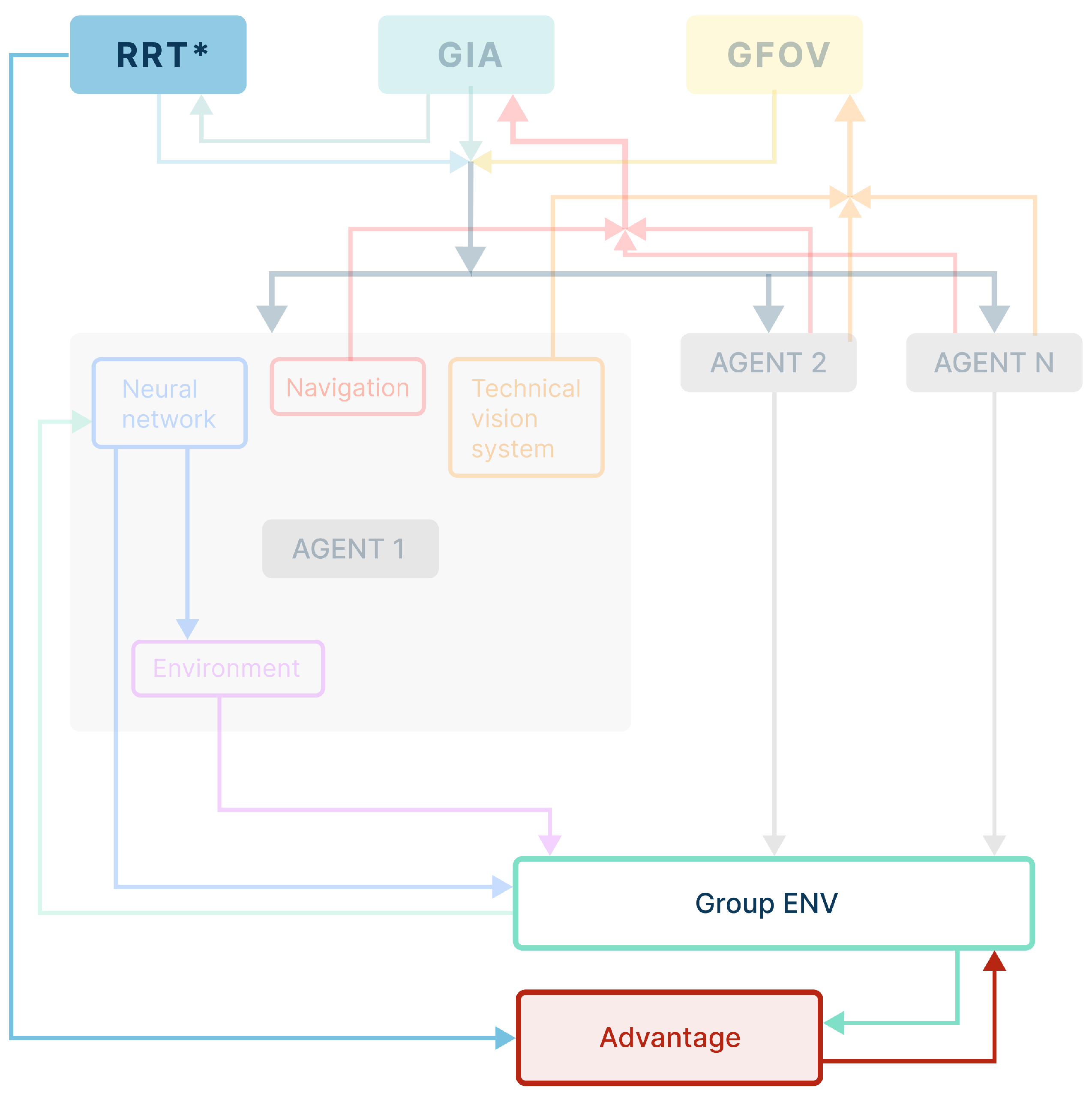
3. Development of the Cascade Architecture of the Neural Network Planning Module for Agents of the MRC Group

The proposed method for forming an interacting group of robots permits data exchange between agents in the group based on their respective vision systems. The global planning module based on the information of the GFOV module determines a global motion trajectory. The GIA generation module allows the best way of rebuilding the group to be chosen while avoiding obstacles and taking into account the distance necessary to maintain communication between the agents. The architecture of the developed intelligent cascade planning system, considering both the input and output parameters, is presented in Figure 8. To generate control signals for the actuators of each agent of the group, the internal planning logic was implemented based on an artificial neural network and a DL method for the agents.
Operation of the algorithm on the basis of the cascade intelligent planner, shown in Figure 8, is as follows. First, the available GPOV, GIA, and RRT* modules receive input data from the navigation systems and VS of each agent in the group. As presented above, the result of the GPOV operation is a data array describing the current state of the shared field of view, including the classes of objects. The GIA algorithm provides data on the current state of the formation in the form of ε n and D . The auxiliary trajectory planning module calculates the recommended trajectory in the form of H g r o u p . This dataset is sent to the neural system for path planning of each agent of the group, which is responsible for the action of each agent in the group during learning. Thus, each agent has its own environment (the agent’s local environment E a g e n t ), from which it receives feedback in the form of an updated state S and reward R. At the same time, the agent is in constant interaction with other agents in the group, meaning that its local environment is part of the overall group environment E a g e n t E g r o u p .
In order to make adjustments with group-wide impact, the last module of the cascade architecture to be introduced is the Overall group environment analysis module. This module determines the intragroup state of each agent and the group-wide reward for agents for selected actions A.
The resulting decentralized group planning system is easily implemented and scalable. The system implements a cascade of algorithms, which together prepare and generate data for the agents’ onboard neural network training.

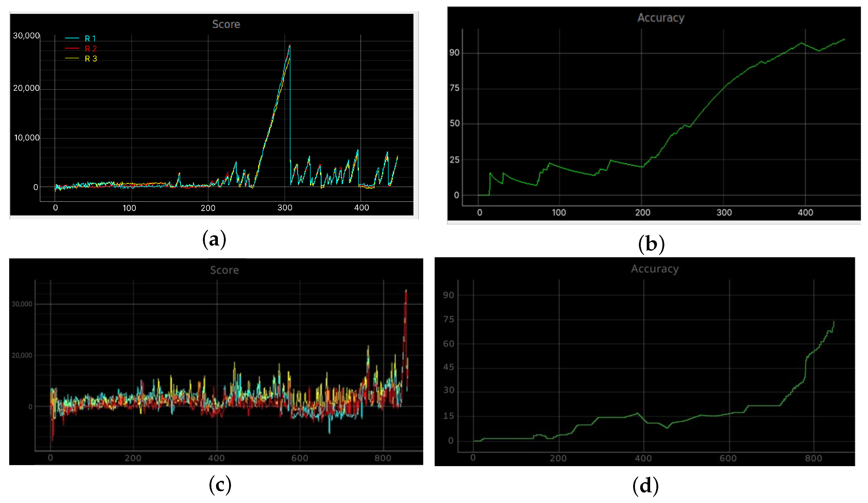
3.1. Development of a Neural Network Agent Action Planner Module in the MRC Group

The data used as input for the agents’ neural network result from either the operation itself or calculations carried out by the modules described above. A planner module is implemented on a fully connected neural network basis. The DQN approach is used as the main training method [61,70]. The agent has its own memory of (M) = 20,000 elements, storing a set of values ( S , R , S , A , Q ) that describe the previous state, reward, current state, and recommended maximum best value of the selected action. The agent model is presented in Figure 9. The rule that forms the basis for training the agent’s neural network planner is shown in Formula (7).
r t + γ · max a ! Q · S t + 1 , a ; θ Q · S t , a t ; θ 2
The target network and Q-network (shown in the figure below) have an identical structure.
The architecture of the developed neural network is shown in Figure 10. The neural network has 364 input values, which include arrays of distances between the agents of the group, the distance and direction angle of the current agent in relation to the target, data from the VS, the identifier of the detected object (an obstacle or an agent of the group), and the agent’s current status. This information enters the internal block of the neural network, which consists of three dense layers of 64 neurons each and two dropout layers with an exclusion parameter equal to 0.2. The RMSProp optimizer with parameters l e a r n i n g r a t e = 0.00025 , ρ = 0.9 , and ε = 1 6 was chosen as the activation function.
The agent’s neural network module provides the error calculation function based on the Huber loss (8):
Huber loss = 1 2 y y p 2 , y y p δ δ y y p 1 2 δ 2 , y y p > δ ,
where y is the current value of the AV states, y p is the predicted values of the AV states, and δ is the error function tuning factor, which in this case is δ = 1 . A previously developed software simulation complex was used as an environment to conduct training. The interaction of the agent with the environment occurs on the basis of five possible actions, which are presented in Figure 11.
When interacting with the environment, an AV changes its state from (S) to ( S ) based on a reward R r . The expression used to describe the internal policy is responsible for the AV’s reward function is as follows (9):
R r = Y r ( A ) 5 D rate D rate = 2 D cur / D goal Y r ( A ) = 1 4 | 0.5 0.5 α | α = heading
where h e a d i n g is the agent’s current heading, D rate , Y r ( A ) is the component of the reward based on the distance and the agent’s current heading, and D goal is the agent’s distance to the target.

3.2. Development of a Neural Network Correction Module for MRC Group Action Planning

The neural network correction module for planning the actions of the MRC group is responsible for evaluating the actions performed by each agent in the group. The primary objective of this module is to form an intragroup policy of behaviour through the analysis of states and rewards ( S n , R r n ) for all agents in the local E a g e n t and overall group E g r o u p environments. The function that describes the intragroup interaction policy of agents, which is responsible for the group reward component formation, is provided by expression (12) below:
R g 13 = e D 13 2.1 if D 13 < 2.1 e 1.9 D 13 if D 13 < 1.9 3 other cases
R g 12 = e D 12 ( 2 + 0.1 ) if D 12 > 2 + 0.1 e ( 2 0.1 ) D 12 if D 12 < 2 0.1 3 other cases
R g 1 = R r + R g 12 + R g 13
where several scenes in the software simulation complex were implemented in order to train a group of three agents: a scene without obstacles, one with stationary obstacles, and one with dynamically changing obstacles. The scenes are shown in Figure 12. It should be noted that at this stage an initial structure consisting of a wedge-type formation was considered.
Training was conducted on a PC equipped with an NVIDIA Geforce 3060 video card with 12 Gb RAM (considering the pre-installed CUDA 11.7), 64 Gb DDR4 RAM, and Intel Core i9 4016 Gz processor. The elapsed training time varied for each scene: 2 h for the first scene, 10 h for the second scene, and about 15 h for the third scene.
The graphs presented below in Figure 13 describe the learning results for the three generated scenes. An example of training a group on the scene without obstacles with the GIA display and its changes during motion is shown in Figure 14.
In the Figure 13, the plots (a) and (c) demonstrate the results of group training in the environment without obstacles. As can be seen in the figures, the developed group neural network successfully achieves (with 90% probability) accident-free group motion after 400 training epochs (episodes), which we considered to fulfill the conditions specified by the GIA and shared field of view algorithms for reaching the target coordinates. The plots (b) and (c) demonstrate the results of group training in the environment with dynamic obstacles. After 800 epochs (episodes) of training, the neural network successfully copes (with 75% probability) with the task of group motion to reach the target coordinates while avoiding obstacles.

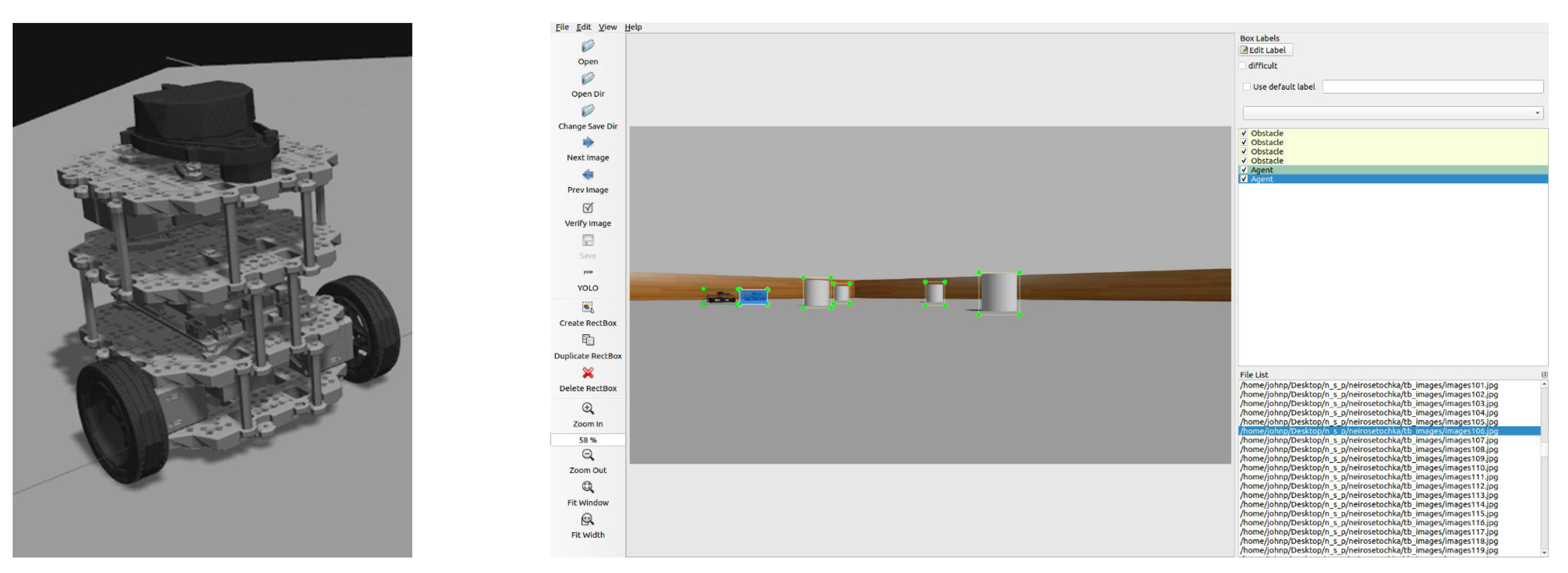
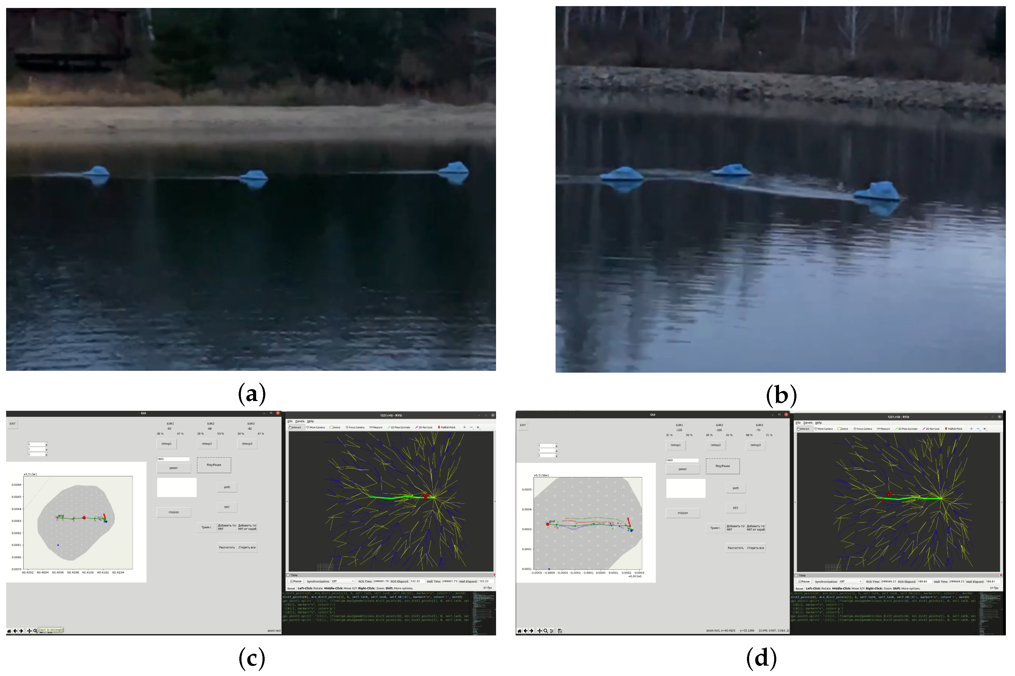
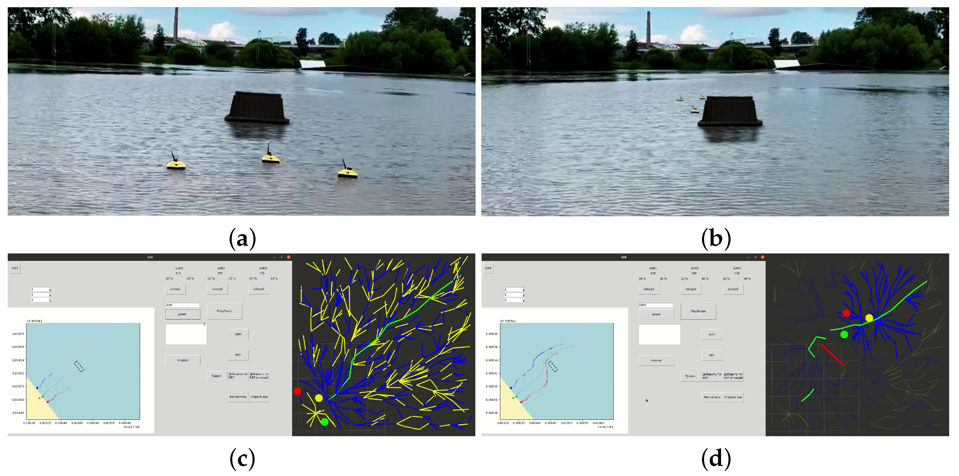
4. Full-Scale Trials of the Developed Modules’ Operation for Planning and Intragroup Interaction Using the Example of a Displacement MRC

In this section, we present full-scale tests of modules based on the proposed method. In future works, we plan to use the results of full-scale trials for hardware integration of a neural network planning system with the mathematical models of robotic systems. The set of actions of TurtleBot3 is comparable to the set of actions of mini-boats, as in both cases there are two engines.
To test the developed algorithms, experimental models of crewless boats were implemented. A schematic layout of the considered crewless boat’s equipment is shown in Figure 15.
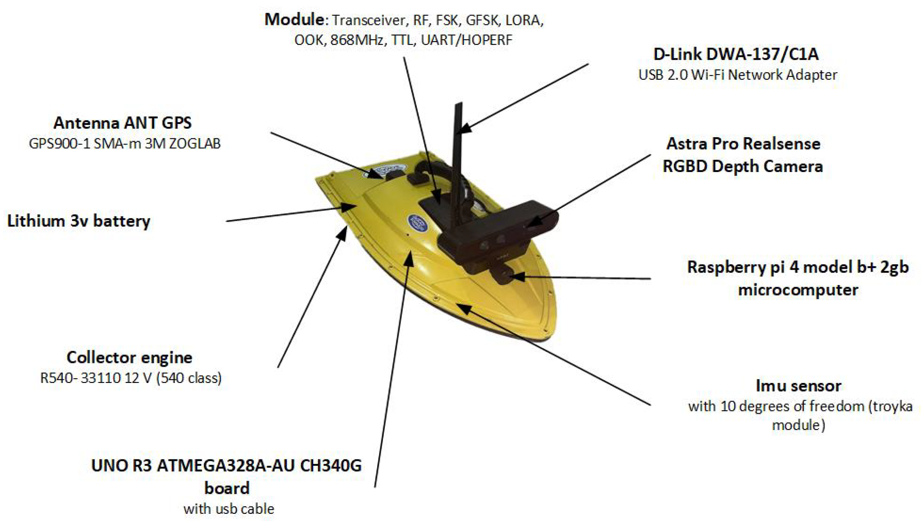
  • Module: Transceiver, RF, FSK, GFSK, LORA, OOK, 868 MHz, TTL, UART/HOPERF
  • Antenna ant gps GPS900-1 SMA-m 3M ZOGLAB
  • Lithium 3v battery
  • Two Collector engine R540- 33110 12 V (540 class)
  • UNO R3 ATMEGA328A-AU CH340G board with USB cable
  • Imu sensor with 10 degrees of freedom (troyka module)
  • Raspberry PI 4 model b+ 2 Gb microcomputer
  • D-Link DWA-137/C1A USB 2.0 Wi-Fi Network Adapter
  • Astra Pro Realsense RGBD Depth Camera
In our systemRGBD depth cameras based on Structured light technology are used as the main devices for obtaining information on obstacles, as it is shown in the Figure 16. The option of using Depth from stereo technology is under consideration for future stages. There are issues with structured light cameras, among which a few should be mentioned in this context. The main issue is that they produce a noisy depth map in open air, as solar radiation contains an infrared spectrum. Another issue is that they provide a large number of reflections when used in water.
Operation trials of the group management system were carried out; it was necessary to test the RRT algorithm as a global planning system, the system for depth map generation, and the speed of group interaction.
Due to the unaccounted-for influence of sunlight on the data obtained from the depth camera, we had to abandon the system test with the camera; these tests will need to be carried out in future research.
A formalized statement of the mission assigned to a group of robots can be represented as follows: it is necessary to ensure the movement of a group of marine robotic systems through the key points of the route, taking into account the preservation of the group formation (in the full-scale tests, the movement of the group was in a “front”-type formation) while taking into account obstacle avoidance and maintaining the necessary distance to maintain a communication channel between the robots. In thie experiment, the target distance between the robots was 2 m and the tolerance corridor between robots was 0.5 m.
The full-scale tests included the following steps:
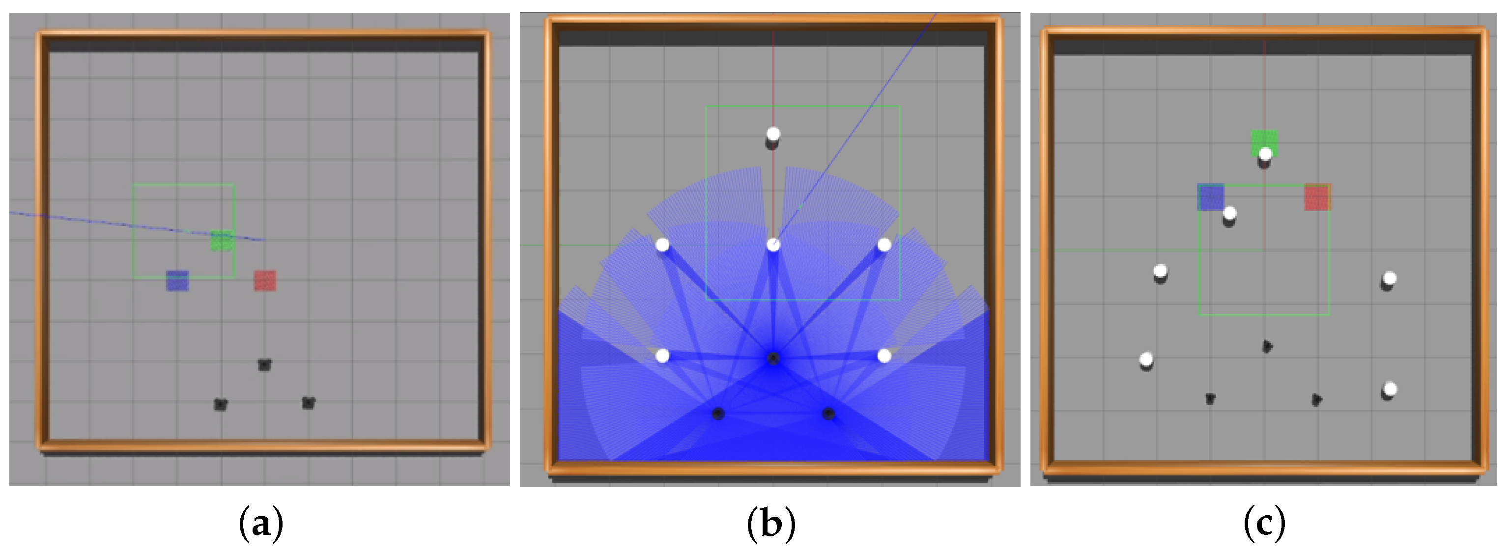
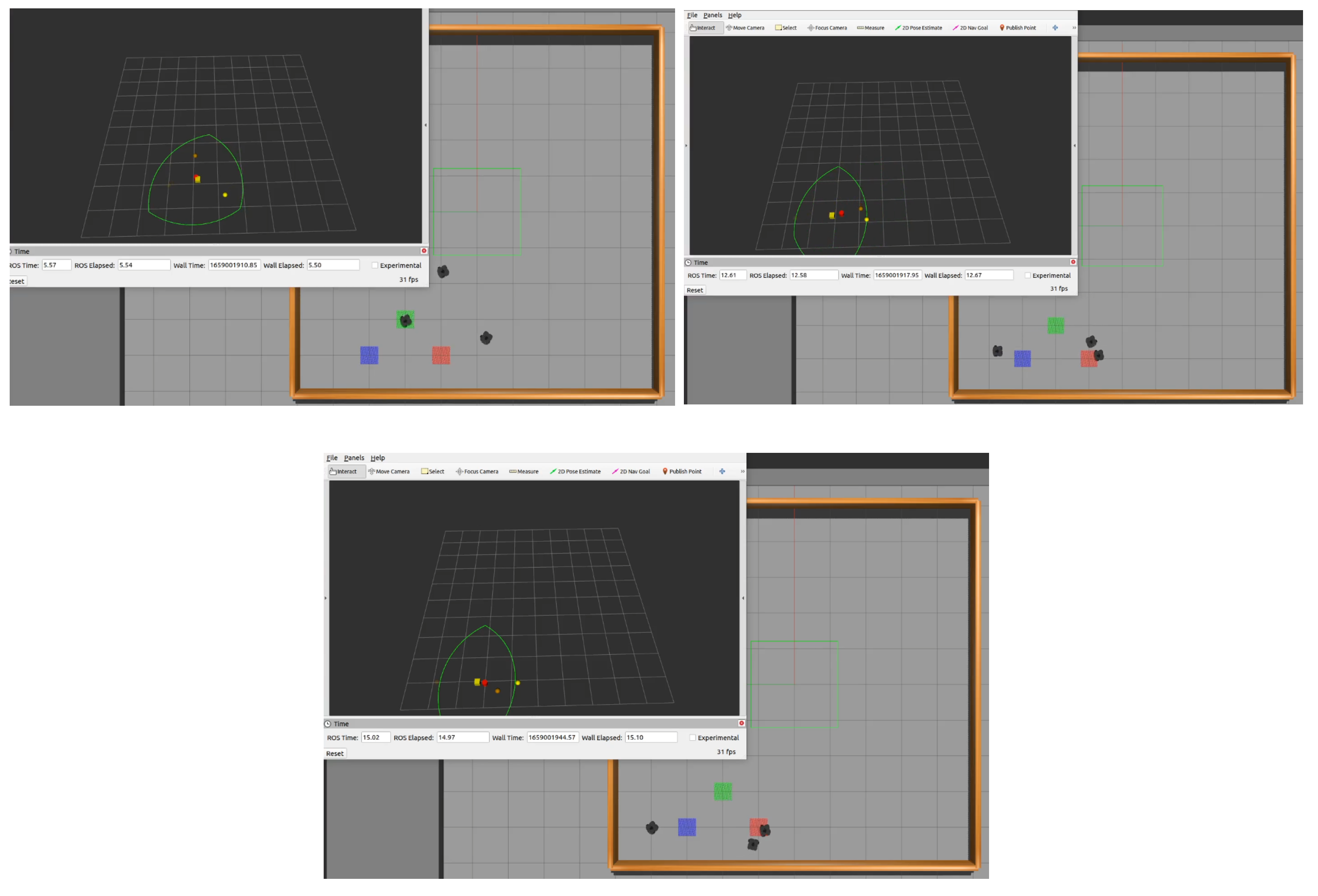
  • Study of the local and global planning performance under real conditions and in two cases (without obstacles and with obstacles).
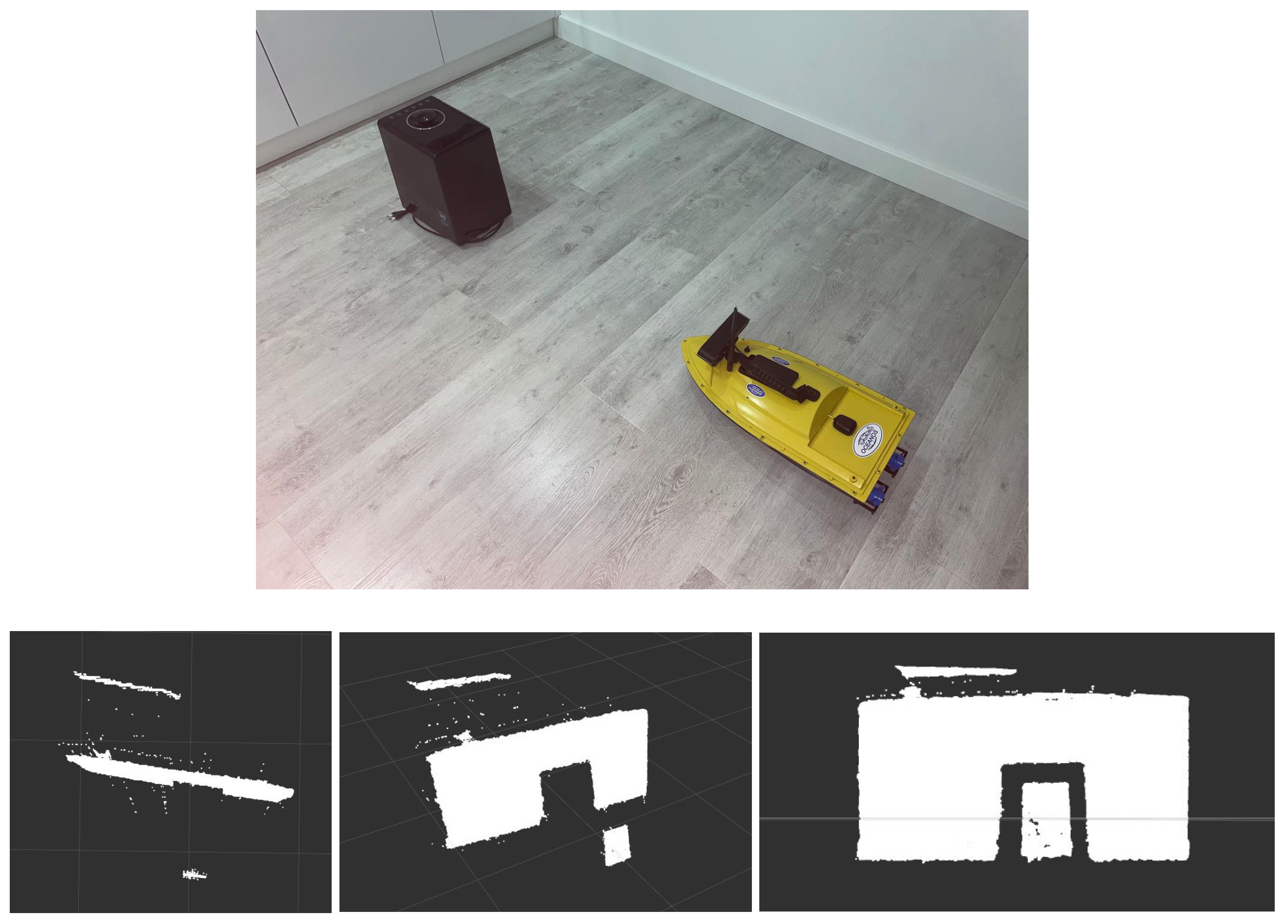
  • Operability validation of the technical vision system and the information exchange module (volumes of transmitted data) in order to build up a common field of view of the group.
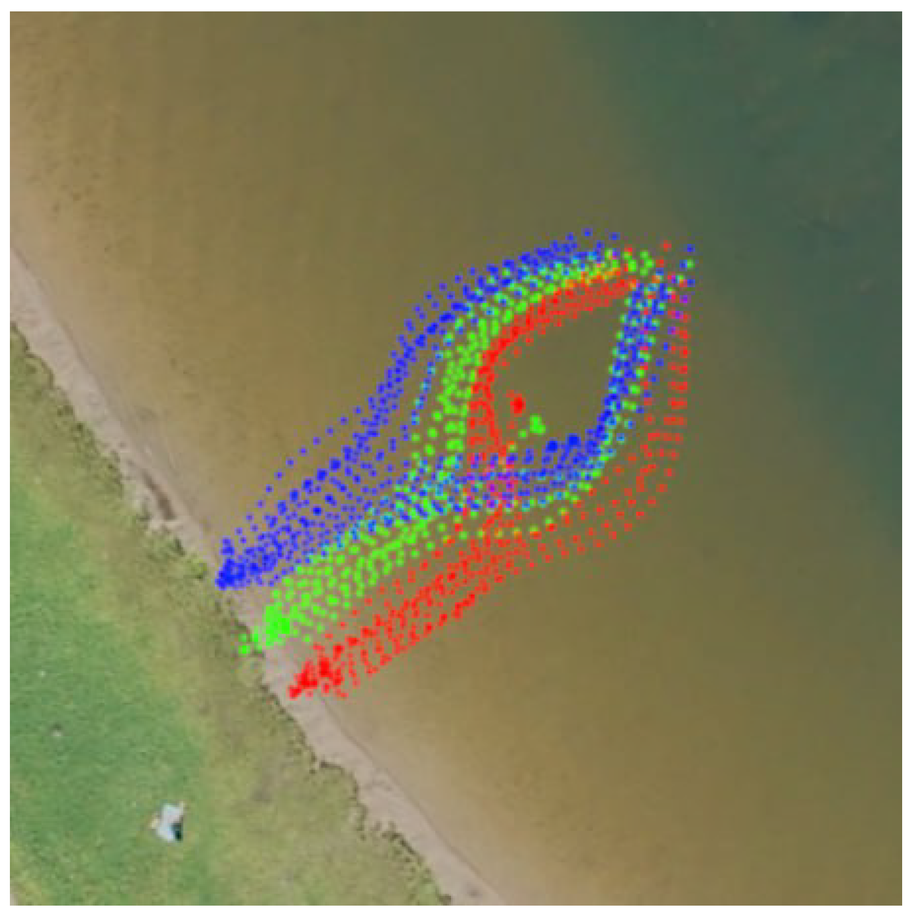
  • Formation of a database from the VS system, which is subsequently loaded into the neural network block in order to classify group agents.
  • Integration of data obtained from the vision system into the neural network planning system implemented on the hardware of crewless boats.
The goal of the experiment was to move the group from point A to point B. To do this, ten observed measurements were used. The direct distance from point A to point B was 25 m. The RRT tree building time for each experiment is presented in Table 1.
The data transmitted from each crewless boat were as follows:
  • Service information, navigation information, and 3D camera data = 1.2 mb;
  • Service information, navigation information, and LIDAR data = 1.5 kb.
The software of the crewless boat was implemented on the ROS in order to simplify the integration and porting of existing automatic control system (hereinafter referred to as ACS) and planning modules. The full-scale experiment was carried out in the inner water areas of St. Petersburg, Russia and Chelyabinsk, Russia. The result of group operation of the crewless boats is shown in Figure 17.
The conducted experiment made it possible to test the application of the developed algorithms in a real environment, considering the use of the implemented crewless boat hardware and software platform. An operator GUI was implemented to display the necessary information about the crewless boat motion, target coordinates, and actual trajectories of the agents in the group. In addition, the GUI was able to show the operation of the RRT* algorithm in real time.
To ensure VS operation in the full-scale trials, we decided to replace the Astra Pro Realsense 3D camera with the RPLIDAR S2 30 m TOF LIDAR, which has a visibility range of 30 m.
It should be noted that the visibility of the LIDAR was limited in the experiment by its visibility sector of +/− 30 degrees from the device bow. Wave motion was compensated for by matrix transformations using the 3D compass data.
The tests consisted of system operation series with a typed obstacle. The key task of the group, as in the simulation, was to bypass a static obstacle. The distance from the starting point to the end point was approximately 30 m, which can be considered a small distance taking into account the possibility of LIDAR action and the speed of the boats. We conducted fifteen launches, three launches of which were unsuccessful. Failure of the LIDAR and of the point cloud merging system were detected during the first and second unsuccessful launches, respectively. During the third unsuccessful launch, there was a problem with the GPS, causing the robots to crash into an obstacle. The RRT tree building time for each experiment is presented in Table 2.
The full-scale trials with an obstacle is shown in Figure 18.
In Figure 18, Figure 18a,b demonstrate group motion and avoidance of the detected obstacle, while Figure 18c,d demonstrate the operator’s GUI, showing the motion trajectories of a group of robots (the operation of the global planning algorithm is displayed). Figure 19 demonstrates the full-scale trials results in RVIZ in real time; the red, yellow, and green circles are the GPS coordinates of the agents, while the red solid line is the obstacle detected by the RPLIDAR S2.
Our experiment demonstrates the possibility of using the developed complex for further study of path construction algorithms, as well as for further study of neural network technologies for group interaction of MRCs. The database of images accumulated during the experiment, which includes models of the crewless boat and planned obstacles, makes it possible to train the developed neural network (a part of the GPOV module). We intend to carry out training of the neural network on real objects and use these results in our subsequent studies on full-scale models of the proposed complex.

5. Conclusions

The present article provides a detailed example of a cascade intelligent system implementation for path planning of a marine AV group. The primary design stages and basic modules of the developed architecture are described.
The proposed system is based on modules that combine neural network approaches and machine learning methods, modules that form a group’s single field of visibility representation, an area of intragroup interaction, and an auxiliary global RRT* planner module.
The developed combination of reinforcement learning algorithms and graphs allows more efficient exploration of the space of possible solutions. The agent can explore both deterministic and probabilistic policies of interaction with the environment.
The available dataset enables deep learning by the neural network of each agent in the group. In addition, constant data exchange with respect to the states of neighbours in the group and subsequent analysis allow a scalable and decentralized system structure to be implemented for intragroup interaction. An additional policy for intragroup state evaluation involves a corrective impact on the training of the cascaded neural network action planner.
A software simulation complex based on the ROS, RVIZ, Gazebo, and ML libraries was developed, making it possible to conduct research on the developed models and planning methods. The obtained simulation results demonstrate the performance of the proposed neural network planning algorithms.
All source code was written in the Python programming language, chosen for this research due to its ease of use and because of the large number of available auxiliary libraries. On the other hand, Python is an interpreted language that is considered slow. When a fully working prototype of this system is ready (using the full-scale models), we plan to migrate to C++ in order to increase the speed of the entire system.
The presented methods and algorithms for group interaction, along with the practical cases, demonstrate the possibility of using an intelligent system as part of the MRC in 2D environments. The existing architecture and the modular principle of building up the planning system make it possible to carry out additional adaptation in order to use this system as part of the AUV, considering the existing limitations and features of AUV operation in a 3D environment.
The simulation model demonstrated a 90% probability of successful group motion mission completion when applying the algorithms in an environment without obstacles and a 75% probability in an environment with moving obstacles. An important issue is to improve the quality of the neural network in environments containing obstacles. One possibility is to consider the use of convolutional layers in the architecture of the neural network of the agent.
Furthermore, we carried out software and hardware implementation to lay further groundwork. An alpha version of a GUI for monitoring and managing a group of MRCs based on the ROS system was implemented. Models of crewless boats were selected as the objects of control, on which the necessary software and hardware, communication, and navigation modules were installed. The conducted full-scale experiment demonstrates the efficiency of the developed algorithms in real-world application conditions. It should be noted that the propulsion parameters of the crewless boats must be improved to ensure greater maneuverability. To permit the subsequent training of the VS module’s neural network and for the developed neural network’s full operation during full-scale experiments, a database was generated using the data collected from the VS.
Further work is aimed at developing the architecture of the cascade intelligent path planner system, specifically, by introducing data on branches from the RRT* auxiliary planning module into the neural network group module and forming an “advantage” system for the agent’s neural network. The modified architecture is shown in Figure 20.
The “advantage” system is to be based on a policy responsible for analyzing each training epoch for a group of agents, the actions they have taken, and the states they have received, as well as the rewards. In addition, analysis of the constructed and used nodes of the RRT* tree should be carried out by this module. We expect the introduction of such a system to lead to an increase in the quality of group neural network training [80].

Author Contributions

Conceptualization, V.R.; methodology, V.R.; validation, A.G. and E.N.; formal analysis, A.B.; investigation, A.M. and A.G.; resources, D.N.; data curation, V.R. and D.N.; software A.M.; writing—original draft preparation, A.M. and I.P.; writing—review and editing, D.N. and E.N.; visualization, A.G. and I.P.; supervision, I.K. and D.N.; project administration, I.K.; funding acquisition, D.N. All authors have read and agreed to the published version of the manuscript.

Funding

This research was partially funded by the Ministry of Science and Higher Education of the Russian Federation as a part of the World-Class Research Center program: Advanced Digital Technologies (contract No. 075-15-2022-312 dated 20 April 2022).

Institutional Review Board Statement

Not applicable.

Informed Consent Statement

Not applicable.

Data Availability Statement

Not applicable.

Conflicts of Interest

The authors declare no conflict of interest.

References

  1. Badrloo, S.; Varshosaz, M.; Pirasteh, S.; Li, J. Image-Based Obstacle Detection Methods for the Safe Navigation of Unmanned Vehicles: A Review. Remote Sens. 2022, 14, 3824. [Google Scholar] [CrossRef]
  2. Aslan, M.F.; Durdu, A.; Yusefi, A.; Yilmaz, A. HVIOnet: A deep learning based hybrid visual–inertial odometry approach for unmanned aerial system position estimation. Neural Netw. 2022, 155, 461–474. [Google Scholar] [CrossRef] [PubMed]
  3. Ji, Q.; Fu, S.; Tan, K.; Thorapalli Muralidharan, S.; Lagrelius, K.; Danelia, D.; Andrikopoulos, G.; Wang, X.V.; Wang, L.; Feng, L. Synthesizing the optimal gait of a quadruped robot with soft actuators using deep reinforcement learning. Robot. Comput.-Integr. Manuf. 2022, 78, 102382. [Google Scholar] [CrossRef]
  4. Kouppas, C.; Saada, M.; Meng, Q.; King, M.; Majoe, D. Hybrid autonomous controller for bipedal robot balance with deep reinforcement learning and pattern generators. Robot. Auton. Syst. 2021, 146, 103891. [Google Scholar] [CrossRef]
  5. Gupta, P.; Rasheed, A.; Steen, S. Ship performance monitoring using machine-learning. Ocean Eng. 2022, 254, 111094. [Google Scholar] [CrossRef]
  6. Maevskij, A.M.; Zanin, V.Y.; Kozhemyakin, I.V. Promising high-tech export-oriented and demanded by the domestic market areas of marine robotics. Robot. Tech. Cybern. 2022, 10, 5–13. [Google Scholar] [CrossRef]
  7. Sokolov, S.S.; Nyrkov, A.P.; Chernyi, S.G.; Zhilenkov, A.A. The Use Robotics for Underwater Research Complex Objects. Adv. Intell. Syst. Comput. 2017, 556, 421–427. [Google Scholar] [CrossRef]
  8. Pshikhopov, V.; Gurenko, B.V.; Beresnev, M.; Nazarkin, A. Implementation of underwater glider and identification of its parameters. J. Teknol. 2016, 78, 109–114. [Google Scholar] [CrossRef] [Green Version]
  9. da Silva Tchilian, R.; Rafikova, E.; Gafurov, S.A.; Rafikov, M. Optimal Control of an Underwater Glider Vehicle. Procedia Eng. 2017, 176, 732–740. [Google Scholar] [CrossRef]
  10. Tian, X.; Zhang, L.; Zhang, H. Research on Sailing Efficiency of Hybrid-Driven Underwater Glider at Zero Angle of Attack. J. Mar. Sci. Eng. 2022, 10, 21. [Google Scholar] [CrossRef]
  11. Wang, P.; Xinliang, T.; Wenyue, L.; Zhihuan, H.; Yong, L. Dynamic modeling and simulations of the wave glider. Appl. Math. Model. 2019, 66, 77–96. [Google Scholar] [CrossRef]
  12. Nechaev, Y.I.; Nikushchenko, D.V. Interpretation function of dynamic of an underwater vehicle in non-stationary environment. Mar. Intellect. Technol. 2022, 2, 139–147. [Google Scholar] [CrossRef]
  13. Nechaev, Y.I.; Nikushchenko, D.V. Digital models of unsteady dynamics of underwater vehicle in the cloud computing environment. Mar. Intellect. Technol. 2022, 3, 346–352. [Google Scholar] [CrossRef]
  14. Li, D.; Du, L. AUV Trajectory Tracking Models and Control Strategies: A Review. J. Mar. Sci. Eng. 2021, 9, 1020. [Google Scholar] [CrossRef]
  15. Kot, R. Review of Collision Avoidance and Path Planning Algorithms Used in Autonomous Underwater Vehicles. Electronics 2022, 11, 2301. [Google Scholar] [CrossRef]
  16. Zhilenkov, A.A.; Chernyi, S.G.; Sokolov, S.S.; Nyrkov, A.P. Intelligent autonomous navigation system for UAV in randomly changing environmental conditions. J. Intell. Fuzzy Syst. 2020, 38, 6619–6625. [Google Scholar] [CrossRef]
  17. Beloglazov, D.A.; Guzik, V.F.; Kosenko, E.Y.; Kruhmalev, V.; Medvedev, M.Y.; Pereverzev, V.A.; Pshihopov, V.H.; Solovyov, V.V.; Finaev, V.I.; P’yavchenko, A.N.; et al. Intelligent Trajectory Planning of Moving Objects in Environments with Obstacles; Fizmatlit: Moscow, Russia, 2014; p. 450. (In Russian) [Google Scholar]
  18. Gul, F.; Mir, I.; Abualigah, L.; Sumari, P.; Forestiero, A. A Consolidated Review of Path Planning and Optimization Techniques: Technical Perspectives and Future Directions. Electronics 2021, 10, 2250. [Google Scholar] [CrossRef]
  19. Kenzin, M.; Bychkov, I.; Maksimkin, N. A Hierarchical Approach to Intelligent Mission Planning for Heterogeneous Fleets of Autonomous Underwater Vehicles. J. Mar. Sci. Eng. 2022, 10, 1639. [Google Scholar] [CrossRef]
  20. Shu, M.; Zheng, X.; Li, F.; Wang, K.; Li, Q. Numerical Simulation of Time-Optimal Path Planning for Autonomous Underwater Vehicles Using a Markov Decision Process Method. Appl. Sci. 2022, 12, 3064. [Google Scholar] [CrossRef]
  21. Maevskij, A.M.; Zanin, V.Y.; Kozhemyakin, I. Development of a combined control system for resident/intervention AUV based on behavioral methods. Izv. SFedU. Eng. Sci. 2020, 1, 119–133. [Google Scholar] [CrossRef]
  22. Maevskij, A.; Gorelyi, A.; Morozov, R. Development of a Hybrid Method for Planning the Movement of a Group of Marine Robotic Complexes in a Priori Unknown Environment with Obstacles. In Proceedings of the 2021 IEEE 22nd International Conference of Young Professionals in Electron Devices and Materials (EDM), Souzga, Russia, 30 June–4 July 2021; pp. 461–466. [Google Scholar] [CrossRef]
  23. Li, J.H.; Kang, H.; Kim, M.G.; Lee, M.J.; Cho, G.R.; Jin, H.S. Adaptive Formation Control of Multiple Underactuated Autonomous Underwater Vehicles. J. Mar. Sci. Eng. 2022, 10, 1233. [Google Scholar] [CrossRef]
  24. Pshihopov, V.H.; Gajduk, A.R.; Medvedev, M.Y.; Gontar, D.N.; Solovyov, V.V.; Martyanov, O.V. The concept of the robotics operational group. Izv. Yufu. Tekhnicheskie-Nauk. Izv. Sfedu. Eng. Sci. 2020, 1, 6–16. (In Russian) [Google Scholar]
  25. Pshikhopov, V.; Medvedev, M.; Gaiduk, A.; Kolesnikov, A. Control Method for Heterogeneous Vehicle Groups Control in Obstructed 2-D Environments. Lect. Notes Comput. Sci. 2016, 9812, 40–47. [Google Scholar] [CrossRef]
  26. Pshikhopov, V. Path Planning for Vehicles Operating in Uncertain 2D Environments; Butterworth-Heinemann: Woburn, MA, USA, 2017; p. 298. [Google Scholar] [CrossRef]
  27. Zhou, W.J.; Subagdja, B.; Tan, A.H.; Ong, D.W.S. Hierarchical control of multi-agent reinforcement learning team in real-time strategy (RTS) games. Expert Syst. Appl. 2021, 186, 115707. [Google Scholar] [CrossRef]
  28. Zheng, H.; Li, X.; Chen, J.; Dong, J.; Zhang, Y.; Lin, C. One4All: Manipulate One Agent to Poison the Cooperative Multi-Agent Reinforcement Learning. Comput. Secur. 2023, 124, 103005. [Google Scholar] [CrossRef]
  29. Vinyals, O.; Babuschkin, I.; Czarnecki, W.M.; Mathieu, M.; Dudzik, A.; Chung, J.; Choi, D.H.; Powell, R.; Ewalds, T.; Georgiev, P.; et al. Grandmaster level in StarCraft II using multi-agent reinforcement learning. Nature 2019, 575, 350–354. [Google Scholar] [CrossRef]
  30. Samvelyan, M.; Rashid, T.; Witt, C.S.D.; Farquhar, G.; Nardelli, N.; Rudner, T.G.J.; Hung, C.M.; Torr, P.H.S.; Foerster, J.N.; Whiteson, S. The StarCraft Multi-Agent Challenge. arXiv 2019, arXiv:1902.04043. [Google Scholar] [CrossRef]
  31. Zhang, T.; Xu, H.; Wang, X.; Wu, Y.; Keutzer, K.; Gonzalez, J.; Tian, Y. Multi-Agent Collaboration via Reward Attribution Decomposition. arXiv 2020, arXiv:2010.08531. [Google Scholar] [CrossRef]
  32. Berner, C.; Brockman, G.; Chan, B.; Cheung, V.; Debiak, P.; Dennison, C.; Farhi, D.; Fischer, Q.; Hashme, S.; Hesse, C.; et al. Dota 2 with Large Scale Deep Reinforcement Learning. arXiv 2019, arXiv:1912.06680. [Google Scholar] [CrossRef]
  33. Bonse, R.; Kockelkorn, W.; Smelik, R.M.; Veelders, P.; Moerman, W. Learningagents in Quake III; Technical Report; University of Utrecht, Department of Computer Science: Utrecht, The Netherlands, 2004. [Google Scholar]
  34. Li, J.; Zhai, X.; Xu, J.; Li, C. Target Search Algorithm for AUV Based on Real-Time Perception Maps in Unknown Environment. Machines 2021, 9, 147. [Google Scholar] [CrossRef]
  35. Yang, J.; Xi, M.; Wen, J.; Li, Y.; Song, H.H. A digital twins enabled underwater intelligent internet vehicle path planning system via reinforcement learning and edge computing. Digit. Commun. Netw. 2022. [Google Scholar] [CrossRef]
  36. Shen, L.; Mao, P.; Fang, Q.; Wang, J. A Trajectory Tracking Approach for Aerial Manipulators Using Nonsingular Global Fast Terminal Sliding Mode and an RBF Neural Network. Machines 2022, 10, 1021. [Google Scholar] [CrossRef]
  37. Kim, J.C.; Kim, M.H.; Suh, H.E.; Naseem, M.T.; Lee, C.S. Hybrid Approach for Facial Expression Recognition Using Convolutional Neural Networks and SVM. Appl. Sci. 2022, 12, 5493. [Google Scholar] [CrossRef]
  38. Zhu, J.; Li, A.; Qin, F.; Che, H.; Wang, J. A Novel Hybrid Method Based on Deep Learning for an Integrated Navigation System during DVL Signal Failure. Electronics 2022, 11, 2980. [Google Scholar] [CrossRef]
  39. Shi, J.; Fang, J.; Zhang, Q.; Wu, Q.; Zhang, B.; Gao, F. Dynamic Target Tracking of Autonomous Underwater Vehicle Based on Deep Reinforcement Learning. J. Mar. Sci. Eng. 2022, 10, 1406. [Google Scholar] [CrossRef]
  40. Yan, Z.; Klochkov, Y.; Xi, L. Improving the Accuracy of a Robot by Using Neural Networks (Neural Compensators and Nonlinear Dynamics). Robotics 2022, 11, 83. [Google Scholar] [CrossRef]
  41. Yildirim, S.; Sagiroglu, S. Artificial Neural Networks in Robot Control Systems: A Survey Paper. Math. Comput. Appl. 2002, 7, 103–112. [Google Scholar] [CrossRef]
  42. Liang, J.; Huang, W.; Zhou, F.; Liang, J.; Lin, G.; Xiao, E.; Li, H.; Zhang, X. Double-Loop PID-Type Neural Network Sliding Mode Control of an Uncertain Autonomous Underwater Vehicle Model Based on a Nonlinear High-Order Observer with Unknown Disturbance. Mathematics 2022, 10, 3332. [Google Scholar] [CrossRef]
  43. Anderlini, E.; Parker, G.G.; Thomas, G. Docking Control of an Autonomous Underwater Vehicle Using Reinforcement Learning. Appl. Sci. 2019, 9, 3456. [Google Scholar] [CrossRef] [Green Version]
  44. Carlucho, I.; De Paula, M.; Wang, S.; Petillot, Y.; Acosta, G.G. Adaptive low-level control of autonomous underwater vehicles using deep reinforcement learning. Robot. Auton. Syst. 2018, 107, 71–86. [Google Scholar] [CrossRef] [Green Version]
  45. Wang, J.; Wang, C.; Wei, Y.; Zhang, C. Bounded neural adaptive formation control of multiple underactuated AUVs under uncertain dynamics. ISA Trans. 2020, 105, 111–119. [Google Scholar] [CrossRef] [PubMed]
  46. Wang, J.; Wang, C.; Wei, Y.J.; Zhang, C. Filter-backstepping based neural adaptive formation control of leader-following multiple AUVs in three dimensional space. Ocean Eng. 2020, 201, 107150. [Google Scholar] [CrossRef]
  47. Fahn, C.S.; Chen, S.C.; Wu, P.Y.; Chu, T.L.; Li, C.H.; Hsu, D.Q.; Wang, H.H.; Tsai, H.M. Image and Speech Recognition Technology in the Development of an Elderly Care Robot: Practical Issues Review and Improvement Strategies. Healthcare 2022, 10, 2252. [Google Scholar] [CrossRef] [PubMed]
  48. Rodziewicz-Bielewicz, J.; Korzeń, M. Comparison of Graph Fitting and Sparse Deep Learning Model for Robot Pose Estimation. Sensors 2022, 22, 6518. [Google Scholar] [CrossRef]
  49. Ahmed, I.; Ahmad, M.; Chehri, A.; Hassan, M.M.; Jeon, G. IoT Enabled Deep Learning Based Framework for Multiple Object Detection in Remote Sensing Images. Remote Sens. 2022, 14, 4107. [Google Scholar] [CrossRef]
  50. Hong Khai, T.; Abdullah, S.N.H.S.; Hasan, M.K.; Tarmizi, A. Underwater Fish Detection and Counting Using Mask Regional Convolutional Neural Network. Water 2022, 14, 222. [Google Scholar] [CrossRef]
  51. Li, S.; Yang, W.; Xu, L.; Li, C. An Environmental Perception Framework for Robotic Fish Formation Based on Machine Learning Methods. Appl. Sci. 2019, 9, 3573. [Google Scholar] [CrossRef] [Green Version]
  52. Thum, G.W.; Tang, S.H.; Ahmad, S.A.; Alrifaey, M. Toward a Highly Accurate Classification of Underwater Cable Images via Deep Convolutional Neural Network. J. Mar. Sci. Eng. 2020, 8, 924. [Google Scholar] [CrossRef]
  53. Martin-Abadal, M.; Piñar-Molina, M.; Martorell-Torres, A.; Oliver-Codina, G.; Gonzalez-Cid, Y. Underwater Pipe and Valve 3D Recognition Using Deep Learning Segmentation. J. Mar. Sci. Eng. 2021, 9, 5. [Google Scholar] [CrossRef]
  54. Zhang, G.; Xu, Z.; Hou, Z.; Yang, W.; Liang, J.; Yang, G.; Wang, J.; Wang, H.; Han, C. A Systematic Error Compensation Strategy Based on an Optimized Recurrent Neural Network for Collaborative Robot Dynamics. Appl. Sci. 2020, 10, 6743. [Google Scholar] [CrossRef]
  55. Truong, H.V.A.; Tran, D.T.; Ahn, K.K. A Neural Network Based Sliding Mode Control for Tracking Performance with Parameters Variation of a 3-DOF Manipulator. Appl. Sci. 2019, 9, 2023. [Google Scholar] [CrossRef] [Green Version]
  56. Yeo, S.J.; Choi, W.S.; Hong, S.Y.; Song, J.H. Enhanced Convolutional Neural Network for In Situ AUV Thruster Health Monitoring Using Acoustic Signals. Sensors 2022, 22, 7073. [Google Scholar] [CrossRef]
  57. Wang, W.; Zhang, B.; Wu, K.; Chepinskiy, S.A.; Zhilenkov, A.A.; Chernyi, S.; Krasnov, A.Y. A visual terrain classification method for mobile robots’ navigation based on convolutional neural network and support vector machine. Trans. Inst. Meas. Control 2021, 44, 744–753. [Google Scholar] [CrossRef]
  58. Ren, J.; Huang, X.; Huang, R.N. Efficient Deep Reinforcement Learning for Optimal Path Planning. Electronics 2022, 11, 3628. [Google Scholar] [CrossRef]
  59. Malik, A.; Lischuk, Y.; Henderson, T.; Prazenica, R. A Deep Reinforcement-Learning Approach for Inverse Kinematics Solution of a High Degree of Freedom Robotic Manipulator. Robotics 2022, 11, 44. [Google Scholar] [CrossRef]
  60. Tang, W.; Cheng, C.; Ai, H.; Chen, L. Dual-Arm Robot Trajectory Planning Based on Deep Reinforcement Learning under Complex Environment. Micromachines 2022, 13, 564. [Google Scholar] [CrossRef]
  61. Yuan, J.; Wang, H.; Zhang, H.; Lin, C.; Yu, D.; Li, C. AUV Obstacle Avoidance Planning Based on Deep Reinforcement Learning. J. Mar. Sci. Eng. 2021, 9, 1166. [Google Scholar] [CrossRef]
  62. Lan, W.; Jin, X.; Chang, X.; Wang, T.; Zhou, H.; Tian, W.; Zhou, L. Path planning for underwater gliders in time-varying ocean current using deep reinforcement learning. Ocean Eng. 2022, 262, 112226. [Google Scholar] [CrossRef]
  63. Hadi, B.; Khosravi, A.; Sarhadi, P. Deep reinforcement learning for adaptive path planning and control of an autonomous underwater vehicle. Appl. Ocean Res. 2022, 129, 103326. [Google Scholar] [CrossRef]
  64. Bae, H.; Kim, G.; Kim, J.; Qian, D.; Lee, S. Multi-Robot Path Planning Method Using Reinforcement Learning. Appl. Sci. 2019, 9, 3057. [Google Scholar] [CrossRef] [Green Version]
  65. Luo, T.; Subagdja, B.; Wang, D.; Tan, A.H. Multi-Agent Collaborative Exploration through Graph-based Deep Reinforcement Learning. In Proceedings of the 2019 IEEE International Conference on Agents (ICA), Jinan, China, 18–21 October 2019; pp. 2–7. [Google Scholar] [CrossRef]
  66. Nguyen, T.T.; Nguyen, N.D.; Nahavandi, S. Deep Reinforcement Learning for Multiagent Systems: A Review of Challenges, Solutions, and Applications. IEEE Trans. Cybern. 2020, 50, 3826–3839. [Google Scholar] [CrossRef] [Green Version]
  67. Ahmed, I.H.; Brewitt, C.; Carlucho, I.; Christianos, F.; Dunion, M.; Fosong, E.; Garcin, S.; Guo, S.; Gyevnar, B.; McInroe, T.; et al. Deep Reinforcement Learning for Multi-Agent Interaction. AI Commun. 2022. [Google Scholar] [CrossRef]
  68. Gronauer, S.; Diepold, K. Multi-agent deep reinforcement learning: A survey. Artif. Intell. Rev. 2022, 55, 895–943. [Google Scholar] [CrossRef]
  69. Bahrpeyma, F.; Reichelt, D. A review of the applications of multi-agent reinforcement learning in smart factories. Front. Robot. AI 2022, 9, 1027340. [Google Scholar] [CrossRef]
  70. Xiaofei, Y.; Yilun, S.; Wei, L.; Hui, Y.; Weibo, Z.; Zhengrong, X. Global path planning algorithm based on double DQN for multi-tasks amphibious unmanned surface vehicle. Ocean Eng. 2022, 266, 112809. [Google Scholar] [CrossRef]
  71. Xu, J.; Wang, X.; Liu, P.; Duan, Q. Adaptive Proportional-Integral Sliding Mode-Based Fault Tolerant Control for Autonomous Underwater Vehicles with Thrusters Saturation and Potential Failure. J. Mar. Sci. Eng. 2022, 10, 1614. [Google Scholar] [CrossRef]
  72. Vu, Q.V.; Dinh, T.A.; Nguyen, T.V.; Tran, H.V.; Le, H.X.; Pham, H.V.; Kim, T.D.; Nguyen, L. An Adaptive Hierarchical Sliding Mode Controller for Autonomous Underwater Vehicles. Electronics 2021, 10, 2316. [Google Scholar] [CrossRef]
  73. Zhao, W.; Han, F.; Su, Z.; Qiu, X.; Zhang, J.; Zhao, Y. An Improved Underwater Recognition Algorithm for Subsea X-Tree Key Components Based on Deep Transfer Learning. J. Mar. Sci. Eng. 2022, 10, 1562. [Google Scholar] [CrossRef]
  74. Kot, R. Review of Obstacle Detection Systems for Collision Avoidance of Autonomous Underwater Vehicles Tested in a Real Environment. Electronics 2022, 11, 3615. [Google Scholar] [CrossRef]
  75. Jiang, C.; Ren, H.; Ye, X.; Zhu, J.; Zeng, H.; Nan, Y.; Sun, M.; Ren, X.; Huo, H. Object detection from UAV thermal infrared images and videos using YOLO models. Int. J. Appl. Earth Obs. Geoinf. 2022, 112, 102912. [Google Scholar] [CrossRef]
  76. Official ROS. 2022. Available online: https://www.ros.org/ (accessed on 25 November 2022).
  77. Project TurtleBot3. 2022. Available online: https://emanual.robotis.com/docs/en/platform/turtlebot3/overview/ (accessed on 25 November 2022).
  78. Newman, W. A Systematic Approach to Learning Robot Programming with ROS; CRC Press: Boca Raton, FL, USA, 2017. [Google Scholar] [CrossRef]
  79. Nikushchenko, D.; Maevskij, A.; Kozhemyakin, I.; Ryzhov, V.; Goreliy, A.; Sulima, T. Development of a Structural-Functional Approach for Heterogeneous Glider-Type Marine Robotic Complexes’ Group Interaction to Solve Environmental Monitoring and Patrolling Problems. J. Mar. Sci. Eng. 2022, 10, 1531. [Google Scholar] [CrossRef]
  80. Huang, S.; Kanervisto, A.; Raffin, A.; Wang, W.; Ontañón, S.; Dossa, R.F.J. A2C is a special case of PPO. arXiv 2022, arXiv:2205.09123. [Google Scholar] [CrossRef]
Figure 1. General structure of the developed cascade system for intelligent group motion planning.
Jmse 11 00610 g001
Figure 2. Example MRC group based on the GIA.
Jmse 11 00610 g002
Figure 3. Rewiring process scheme.
Jmse 11 00610 g003
Figure 4. RRT* simulation of the agent’s motion process: (a)—simple obstacle avoidance and (b)—obstacle avoidance in difficult trajectory.
Jmse 11 00610 g004
Figure 5. RRT* simulates the agent’s motion process. (Green, red and pink dots are robots positions).
Jmse 11 00610 g005
Figure 6. An example of neural network operation of the VS module to determine the class of a visible object. (a)—detection of 2 classes and 2 object: agent and obstacle in the visibility zone; (b)—detection of 1 classes and one object–agent in the visibility zone; (c)—detection of 2 classes and 3 object: two agent and one obstacles in the visibility zone; (d)—detection of 2 classes and 3 object: two obstacles and one agent in the visibility zone.
Jmse 11 00610 g006
Figure 7. TurtleBot3 model and database of images.
Jmse 11 00610 g007
Figure 8. Architecture of the cascade intelligent planner for MRC group motion.
Jmse 11 00610 g008
Figure 9. Agent’s neural network architecture based on DQN approach.
Jmse 11 00610 g009
Figure 10. Neural network architecture.
Jmse 11 00610 g010
Figure 11. Agent’s possible actions.
Jmse 11 00610 g011
Figure 12. Developed scenes used to conduct a simulation of the motion planning cascade neural system for a group of objects: (a)—a scene without obstacles; (b)—a scene with stationary obstacles; (c) a scene with dynamically changing obstacles.
Jmse 11 00610 g012
Figure 13. Learning outcomes of the cascade neural network planning system for the MRC group: (a)—total score plot with the group operating in the scene without obstacles; (b)—number of successful mission epochs in a row while operating in the scene without obstacles; (c)—total score plot with the group operating in the scene with obstacles; (d)—number of consecutive successful mission epochs when operating in the scene with moving obstacles.
Jmse 11 00610 g013
Figure 14. An example of GIA changes when simulating group motion of objects in the environment without obstacles.
Jmse 11 00610 g014
Figure 15. Crewless boat model and hardware layout.
Jmse 11 00610 g015
Figure 16. Astra Pro Realsense RGBD Depth Camera point cloud viewing experiment with SMTU.
Jmse 11 00610 g016
Figure 17. The first full-scale trials of group operation of crewless boats: (a) the group starts to move; (b) the group moves towards the target points; (c,d) data on mission progress shown on the operator’s GUI.
Jmse 11 00610 g017
Figure 18. The second full-scale trials of mini-boat group motion considering obstacle avoidance: (a,b)—avoidance of the obstacle; (c,d)—operator’s UI showing the trajectories of the mini-boats.
Jmse 11 00610 g018
Figure 19. Trajectories of the mini-boats in group motion considering obstacle avoidance. Blue, red and green dots corresponding to the trajectory of the first, second and third robot in the group accordingly.
Jmse 11 00610 g019
Figure 20. Architecture of the cascade intelligent path planner of the MRC group, taking the predictive impact into consideration.
Jmse 11 00610 g020
Table 1. Time and path length required to build the RRT tree.
Sample12345678910
Tree building time , sec 0.4330.4510.4420.4320.4420.4120.4210.4120.4230.411
Path length for 1 AV , m 26.8227.11228.02325.9329.1226.8426.9330.0326.3428.53
Path length for 2 AV , m 27.2326.9128.9327.2627.4225.8125.9627.3427.4527.53
Path length for 3 AV , m 26.1229.1427.3426.3226.7528.2128.9626.7828.4429.53
Table 2. RRT tree building time and path length.
Sample123456789101112131415
Tree building time , sec 0.4330.4510.4420.4320.4420.4120.4210.4120.4230.4110.4130.4110.4410.4210.403
Path length for 1 robot , m 38.7946.4646.7539.9239.139.8442.8847.540.1345.4242.7743.840.945.5745.83
Path length for 2 robot , m 44.3841.674037.7839.0244.2637.5844.3541.8740.0943.0544.7847.7241.5637.49
Path length for 3 robot , m 47.3846.438.7441.5745.9440.3541.0642.9346.1341.8444.0347.4837.7837.2241.45
Disclaimer/Publisher’s Note: The statements, opinions and data contained in all publications are solely those of the individual author(s) and contributor(s) and not of MDPI and/or the editor(s). MDPI and/or the editor(s) disclaim responsibility for any injury to people or property resulting from any ideas, methods, instructions or products referred to in the content.

