Review

Rehabilitation Techniques for Offshore Tubular Joints

1
Mechanical Engineering Department, Universiti Teknologi PETRONAS, Seri Iskandar 32610, Malaysia
2
School of Engineering and the Built Environment, Birmingham City University, Birmingham B4 7XG, UK
*
Author to whom correspondence should be addressed.
J. Mar. Sci. Eng. 2023, 11(2), 461; https://doi.org/10.3390/jmse11020461
Submission received: 7 January 2023 / Revised: 5 February 2023 / Accepted: 6 February 2023 / Published: 20 February 2023
(This article belongs to the Special Issue Review Papers in Ocean Engineering)

Abstract

:
Exposure to load and offshore environment degrades the load-bearing capacity of tubular joints, necessitating reinforcement of these joints. Reinforcement is sometimes required for lifespan enhancement or qualification based on new requirements. Available reinforcement techniques include welded rings inside/outside the chord, doubler/collar plate at the brace-chord interface, grout filling, and clamp installation on the joints with/without cement. While these techniques increase the load-bearing capacity of damaged tubular joints, various practical limitations exist. Clamping may require heavy machinery, whereas welding stiffeners involves hot work and may not be permitted sometimes. Fiber-reinforced polymers (FRPs) have immense potential for reinforcing steel structures and are a viable alternative for rehabilitating tubular joints due to their exceptional mechanical and physical characteristics, offering competitive advantages over other methods. FRP reinforcement is becoming more feasible and economical for underwater joints. FRP reinforcement can be either precured, pre-impregnated, or wet layup. Aside from the significance of joint rehabilitation, a document covering the well-known options was lacking. This paper summarizes the advantages and limitations of these reinforcement methods, particularly FRP reinforcement. Possible research directions in FRP reinforcement of tubular joints are also discussed.

1. Introduction

Tubular sectioned members have been used for structural applications since the 1940s. They offer higher torsional rigidity and specific strength compared to conventional steel sections. A typical offshore structure is a truss made of welded circular hollow section (CHS) members. They are usually used in fixed-type offshore structures for their direction-independent stiffness and drag. The connection point between two or more tubular sections is called a tubular joint. Joints for offshore structures can be of various types, made by joining tubular members at different angles, as shown in Figure 1. For a typical tubular joint consisting of two pipes of different diameters, the pipe with larger diameter is called the chord, and the pipe with smaller diameter is called the brace.
The ability of a joint to bear subjected loads is vital for the safe and continuous operation of the facility. Excessive operational loads, cyclones, and tsunamis can cause fatigue damage to the joint, while material and construction flaws reduce the load capacity of the joint. Third-party damages caused by object drop and collision with vehicles during installations, inspection, or hostile strikes can damage structural joints. Additionally, corrosion, an obvious process in the humid offshore climate, is a major cause of pipeline failure. It degrades the joints by thinning the walls, causing stress concentration at the affected zone and modifying the nearby stress and strain field. Corrosion diminishes the load capacity of the joint and thus the whole structure. Reinforcing these critical joints may be necessary to regain or increase the load capacity or rectify the damage. Besides analytical calculations for simple joints, complex tubular joints are analyzed using numerical methods (such as finite element analysis) or experimentation. Various researchers have investigated the joint reinforcement methods, and some have developed mathematical models based on the data obtained in numerical or experimental studies. A single article accumulating the famous techniques for joint rehabilitation was missing in the literature. This article reviews the advantages and disadvantages of the various tubular joint rehabilitation techniques commonly employed in the offshore sector. A viable alternative to conventional methods, FRP reinforcement, is explored, and the challenges in its application to offshore tubular joints are discussed. This article presents a quick overview of the techniques and may help better rehabilitation method selection. Due to extensive utilizations and various configurations, stiffener welding and composites have been discussed in more detail than other options.

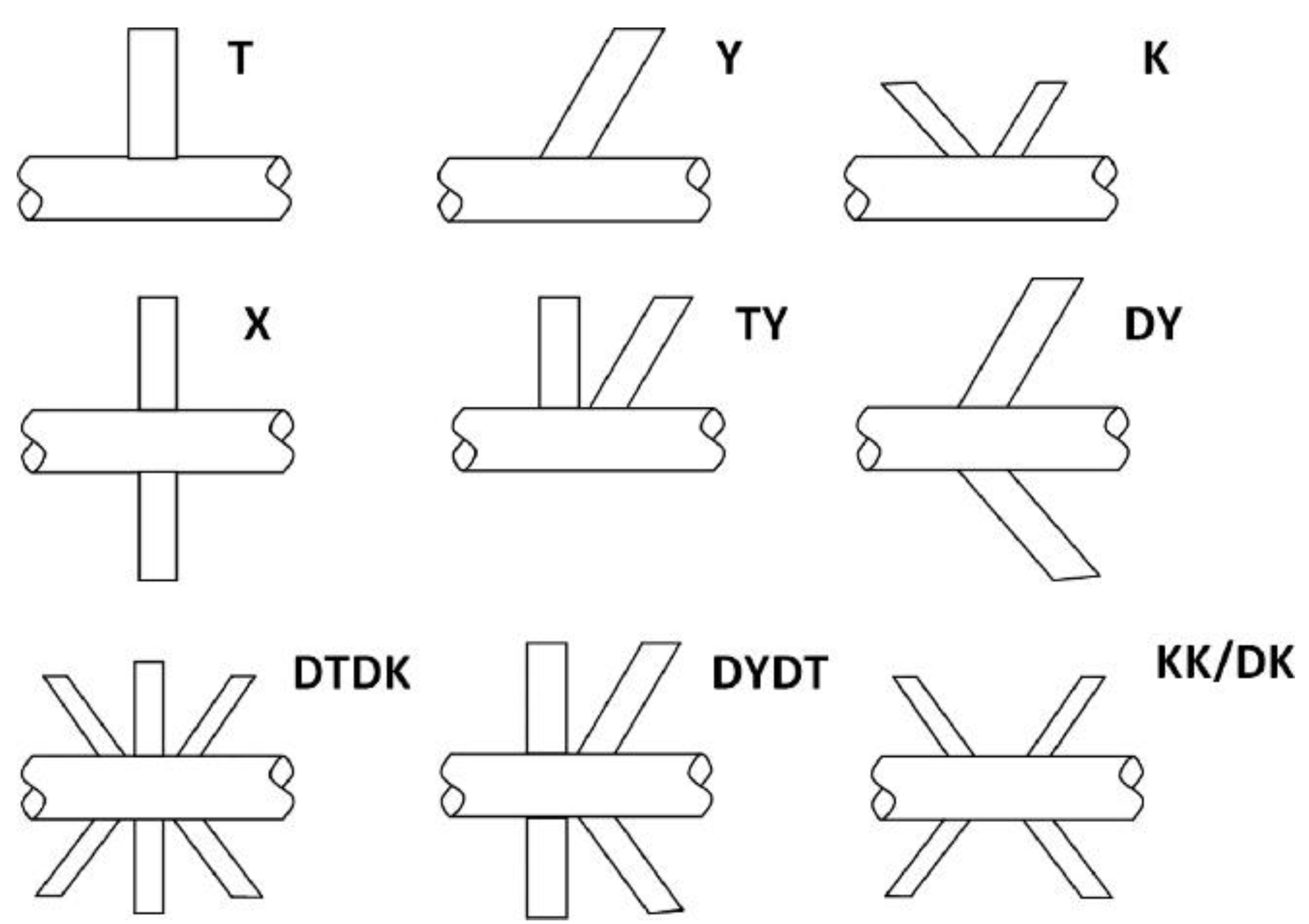
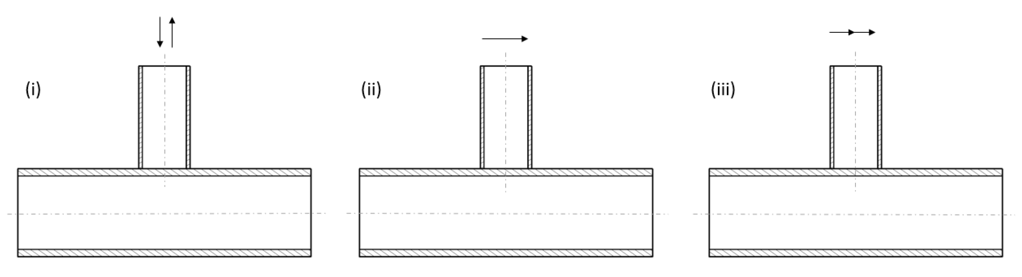
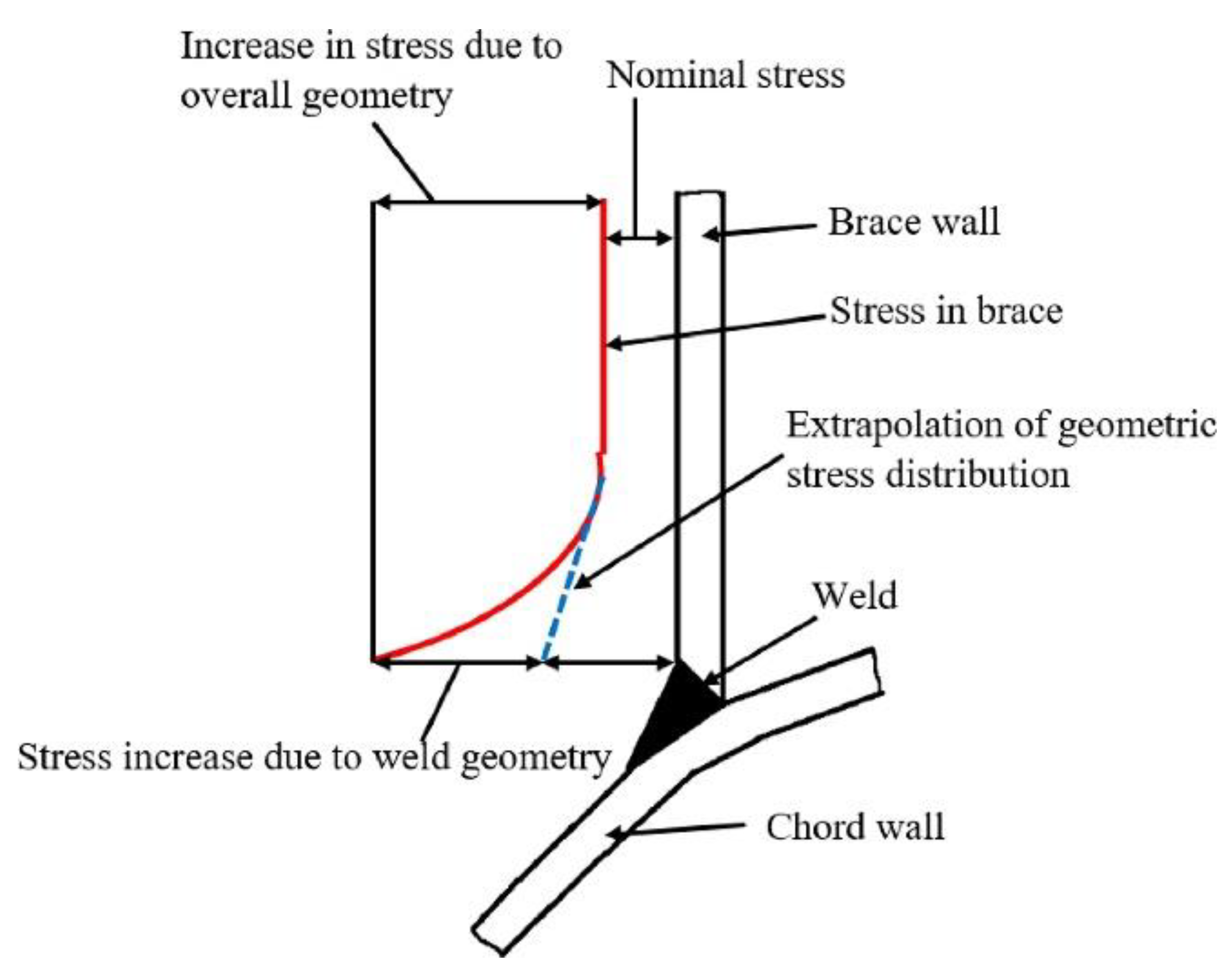
Loads on Offshore Joints

Loads on a tubular joint can be axial tensile, axial compressive, in-plane bending (IPB), or out-plane bending (OPB), as presented in Figure 2. These loads can be present in some combination or one at a time.
While the nominal member stresses in most tubular structures may be within the allowable stress, the complicated geometry of the tubular joint can lead to considerable stress amplifications [2]. Stress concentration is caused at the interface due to geometry change and weld toe, as presented in Figure 3. Depending on the geometry of joints and the type of applied load, plastic failure of the chord, cracking of the brace-chord weld line, separation of the brace from the chord, cracking of the brace, local buckling, shear failure of the chord between neighboring braces, and lamellar ripping of the chord are typical modes of joint failure. Failure of a typical joint imparts extra load to other nearby structural members and may cause damage to these members, with the subsequent collapse of the whole structure.
Fatigue cracks normally begin at the weld toe near the brace-chord interface, where the structural discontinuity induces a high-stress concentration. The total stress at a joint is the summation of all stresses in a tubular joint [3]. The nominal stress ( σ n o m ) calculated using beam theory neglects the localized weld effect and geometric discontinuity. The difference in the geometry of the brace and chord member of the joint results in a difference of deformation, causing a rise in stress at the interface known as geometric stress. The notch of the weld toe causes local stress, and its magnitude depends on the size and geometry of the weld. The effects of notch and weld profile are usually incorporated in the SN curve (stress-number of cycles to failure curve) of the joint. The hotspot stress is expressed as stress concentration factor (SCF) and used in the fatigue design of the tubular joints.
Common causes of fatigue damage in offshore structural joints are wave currents, wave-slamming vortex-induced vibrations, wind-induced vibrations, and transportation loads. To restrain failure of the critical joints, rehabilitation needs may be identified in routine maintenance or special inspections after a tsunami, cyclone, or an on-site accident.

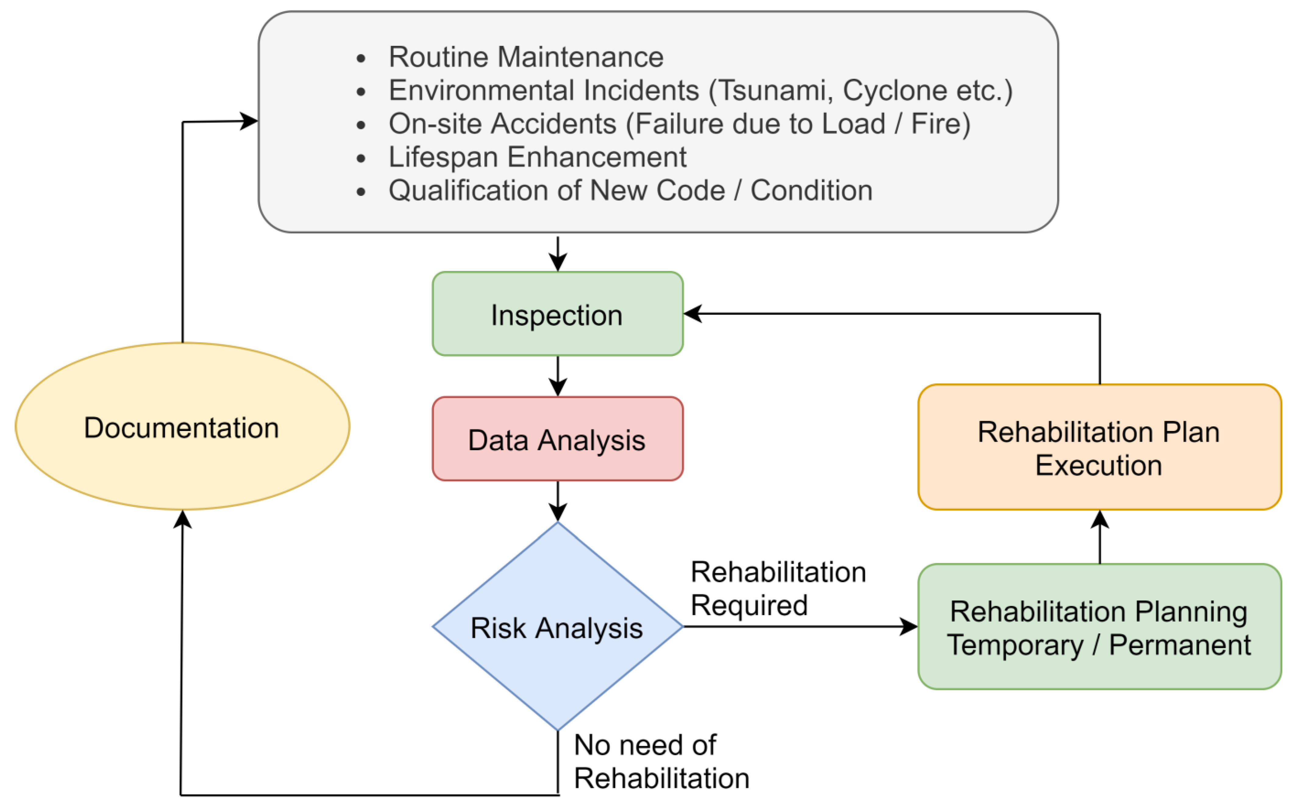
2. Rehabilitation Needs Identification

Many oil and gas facilities worldwide were built decades ago and were not intended to be operational today. For example, 64 out of 190 (more than 30%) fixed offshore structures operated in the Malaysian region by PETRONAS had already exceeded their 30-year design life, and 20% will reach their design life in the next five years [4]. As such, a thorough life enhancement study is required to safely use these offshore facilities beyond their design life. As part of a structural inspection program, periodic inspections of offshore joints are usually conducted based on visual inspection and various techniques such as ultrasonic, radiographic, acoustic, eddy current, strain gauges, and vibration monitoring. A detailed risk analysis is carried out for unusual joints. The risk analysis identifies the frequency and consequences of joint failure based on the inspection data. In addition to the inspection data, design specifications, technical drawings, analysis/re-analysis reports, and maintenance and repair records are all considered in risk analysis. Each of these factors needs to be assigned specific weight/importance, and how they correlate plays an important role in decision-making. Based on the risk analysis, joints requiring rehabilitation are identified. The identified risk level is assessed, and temporary or permanent repair is recommended. The typical process of identifying the need for rehabilitation is presented in Figure 4.
Establishing and maintaining an up-to-date database of methods, experts, suppliers, and costs is crucial to facilitate decision-making for an optimal rehabilitation plan. The rehabilitation may consist of load reduction on the endangered joint, adding a new member(s) to change the load path by transferring load to adjacent structural members, or removing the damaged joint by installing a new one. Sometimes a local rehabilitation scheme is employed around the joint. This rehabilitation process will have one or more operations, including welding, bolting, or adhesive joining. A brief discussion of these operations is presented in the following section.

3. Operations Employed in the Rehabilitation of Tubular Joints
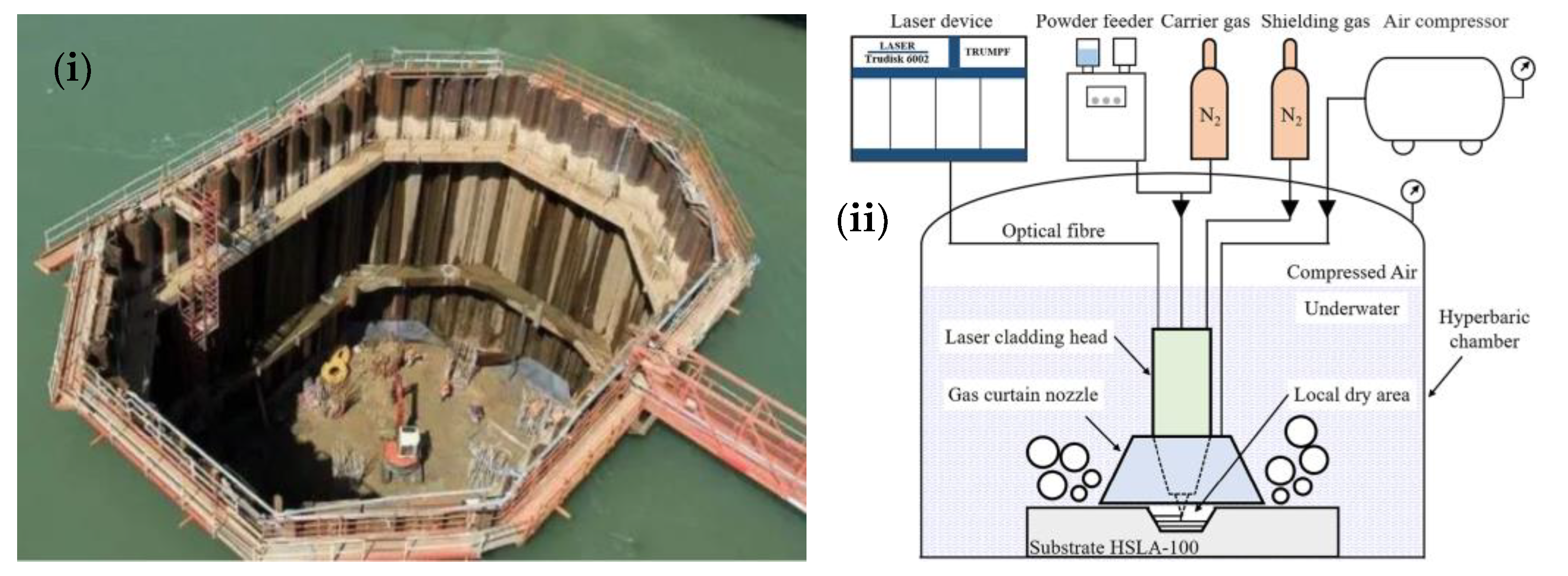
Once the need for rehabilitation is identified, the next step is to consider which operation(s) may be preferred. The selected method will comprise welding, bolting, and/or adhesive joining operations. The following section briefly discusses these operations with their advantages and disadvantages.

3.1. Welding

Welding is one of the best rehabilitation procedures that can be quickly utilized for offshore joints. Dry welding can be carried out if the subject joint is exposed to air. It is preferably employed on the topside (offshore deck). Difficulties arise when the welding process is done underwater since it is impossible to replicate the conditions for maintaining high-quality welding with optimal performance. An enclosure, called a cofferdam, is built around the region of interest in water, and water is pumped out. A typical cofferdam is illustrated in Figure 5i. The process of welding in a cofferdam is similar to dry welding in air. However, the cost and time involved in building a cofferdam make this process unfavorable, specifically if the region of interest is substantially deep. For deeply submerged joints, dry welding is carried out using a pressure-regulated enclosure called hyperbaric chambers, as shown in Figure 5ii. The use of a hyperbaric chamber is an expensive option. Wet welding using specialized electrodes is a viable alternative with less cost and time, as a cofferdam or hyperbaric chamber is not required. However, wet welding may produce welds of inferior quality. Wet welding is sensitive to depth, and the rapid cooling in water makes the optimum metallurgical structure very difficult. Pre- and post-weld operations are also less effective in water. While qualified diver welders are required for wet welding, robotic welding has recently been reported for deeply submerged structures [5]. However, the geometric complexity and limited access to the weld line between joint members limit its application for joint rehabilitation.
Various characteristics of the weld options, classified based on the medium of application, are presented in Table 1. All types of weld operations employ hot work and may present a severe risk to operational offshore facilities. Sometimes welding cannot be carried out without shutdown of operations, causing substantial economic loss. Alternative options are preferred in such circumstances.

3.2. Bolting

Bolting is an effective rehabilitation operation with numerous benefits over others, such as fast application, no wait time necessary to obtain full strength, simple fabrication, ease of removal, and is a widely available off-the-shelf component.
However, there are restrictions on the use of fastening systems in the splash zone and underwater. For example, bolted joints may potentially loosen and are not recommended for fatigue loading. Bare carbon steel bolts are most susceptible to corrosion, and stainless-steel bolts can develop stress corrosion cracking. The corrosion in offshore bolts depends on the environment to which they are exposed. General corrosion, localized corrosion (pitting and crevice), and galvanic corrosion are critical for atmospheric zone bolts, whereas hydrogen embrittlement is most critical in underwater bolts [8]. Conventional painting/coatings and greasing steel fasteners have proven to be ineffective in minimizing corrosion. Various new concepts of bolted connections have been investigated to improve the performance of bolted connections. Fluoropolymer coatings can provide resistance to rusting but their softness makes them susceptible to damage. Ceramic coating mixed with fluoropolymer can offer improved hardness [9]. The use of bolted flange connections in the offshore industry is increasing as it offers some competitive advantages over conventional bolting [10,11].
Existing design codes cover various aspects of bolting design for offshore utilization. Codes by the American Society for Testing and Materials (ASTM), American Petroleum Institute (API), National Association of Corrosion Engineers (NACE), and some military standards discuss corrosion and should be considered for the utilization of bolting in the rehabilitation of offshore joints. ASTM A563 covers nuts’ chemical and mechanical characteristics for externally threaded parts. ASTM A307 covers carbon steel bolts and studs. ASTM A325 covers high-strength heavy hex structural bolts. ASTM F228 covers stainless steel and nickel alloy bolts. ASTM A490 covers bolts with zinc/aluminum corrosion protective coatings called Geomet. API 17A, API 16F, and NACE MR0175/ISO 15,156 have the hardness limits of some specific offshore applications. The only standard covering bolts materials used in sour service environments is NACE MR0175/ISO 15156. MIL-STD-1251A (screws and bolts preferred for design listing) also covers the various design aspects of bolting.

3.3. Adhesives

Adhesive joining can be assumed to be a straightforward process for joint rehabilitation. Adhesively bonded repairs have been used for several decades in the aerospace and civil infrastructure industries for maintenance and life extension. Recently, adhesive repairs have also been used in the marine and oil and gas industries [12]. It does not involve any hot work and can be carried out while the facility is operational. It can be applied to complex shapes and those with limited access, both above and under the water. There are special epoxy resins that are capable of curing underwater. The effectiveness of adhesive joining is independent of the water depth and can be applied to deeply submerged joints, provided the diver is able to withstand the hydrostatic pressure. Proper surface preparation can significantly enhance the effectiveness of interface bonds [13,14]. However, the requirement for surface preparation and cure time sometimes restricts the use of adhesives for rehabilitation, although quick-cure adhesives are available. The literature on employing adhesives for the repair of offshore structures is still limited. When selecting an adhesive, required surface preparation, resin ingredients mixing, curing time, post-cure inspection, heat, and capability to remove the reinforcement, if needed, should be considered. A recommended procedure was developed by several major oil and gas companies for the bonded repairs to non-critical damage cases and found viable for frequently encountered damage scenarios [12].

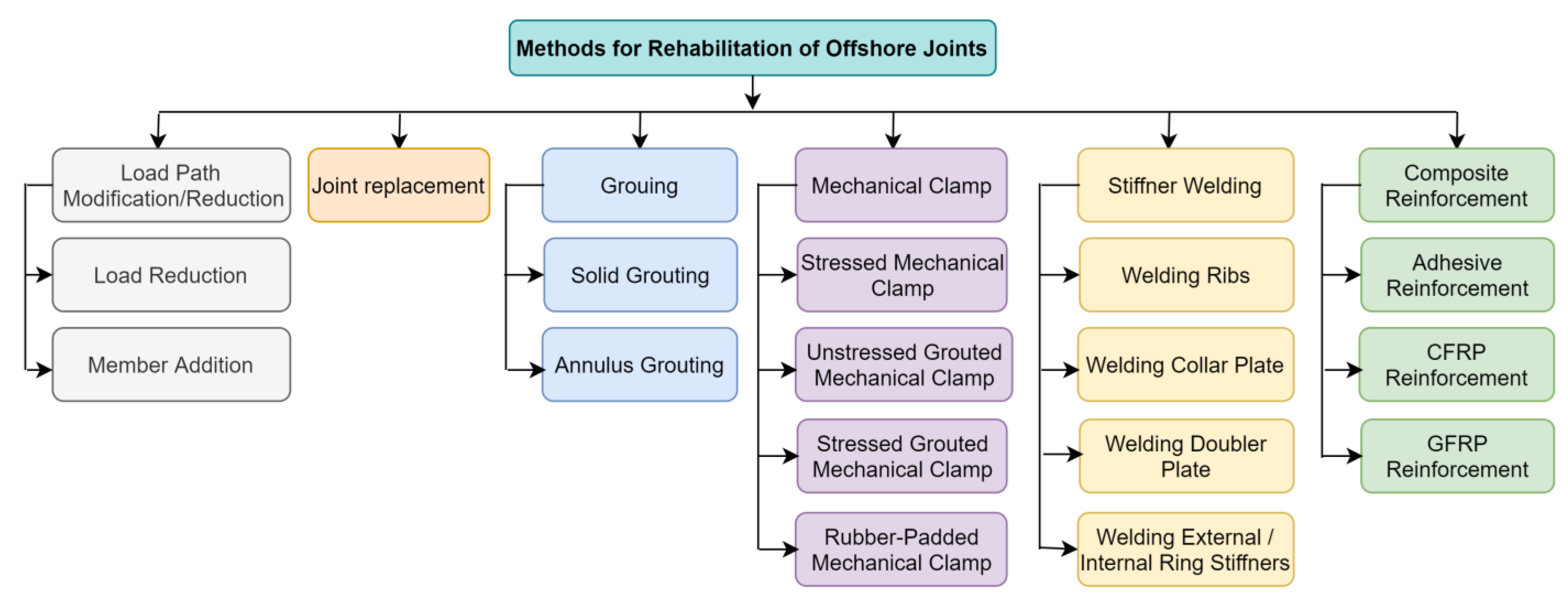
4. Methods of Offshore Joint Rehabilitation

Various repair techniques are available to rehabilitate tubular members [15]. The selection of rehabilitation techniques should be based on technical, operational, and economic factors. Specifically: (1) Reliability of the rehabilitation method, (2) costs of implementation, (3) offshore support requirements, (4) depth restrictions, (5) technical proficiency, (6) experience with similar tasks, (7) time required for installation, (8) post-installation inspection, (9) potential problem areas, (10) service life, (11) environmental effects, (12) code/standard requirements/obligations, (13) removability, and (14) operator preferences. Figure 6 summarizes the different rehabilitation techniques employed for offshore joints. Each method has its limitations and advantages. The following sections present a brief discussion of these techniques:

4.1. Load Path Modification/Load Reduction

If a joint of an offshore structure has deteriorated, the serviceability of the joint is assessed. This assessment can be based on visual inspection, metrology, finite element analysis (FEA), or a combination of these. If the likelihood of severe loading is low, the joint can continue to be used for some time under reduced loads. This load reduction is not a permanent solution and may be employed as a temporary remedy; for example, modification in operations or reduction of dead weight at the deck. Usually, the joint is planned to be under reduced load until the next scheduled maintenance or shutdown, after which permanent rehabilitation will be carried out for the damaged joint.

4.2. Joint Replacement
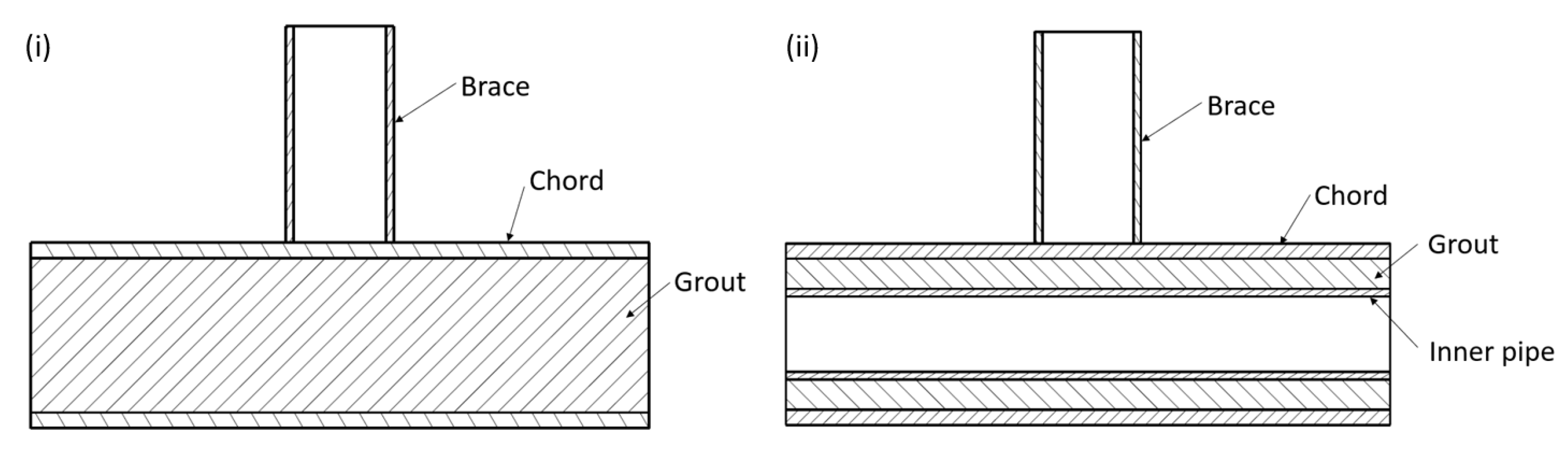
Replacement of a structural joint is considered a legitimate method of repair. It is often necessary to prevent additional damage or crack propagation in the structure. The decision to remove the damaged joint must be based on a detailed engineering analysis. It may be necessary to install additional members for transferring load during the replacement process. Once the joint is successfully replaced, the designed strength can be restored. However, accessibility, load isolation, and requirements of sophisticated machinery, such as pipe cutters, lifts, and rewelding, result in this option very rarely being employed for the rehabilitation of offshore joints. The replacement process is further complicated when the joint is underwater.

4.3. Grout Filling

Grouting is carried out by filling the whole joint or just the chord with some cementitious material to enhance the stiffness or load-bearing capacity of the tubular joint while keeping the outer dimensions unchanged [16]. It can be carried out without interrupting the operations of the offshore facility. Grout filling has been an effective repair method for local buckling and dents in tubular joints. It prevents localized shell bending, buckling, and section ovalization. Grout is sometimes filled between the joint and clamp to form a grouted clamp, which is discussed in the next section on mechanical clamping of tubular joints.
Grouting can be either solid or annular-shaped. In the case of solid grouting, the tubular joint or chord of the joint is filled with cementitious material, as presented in Figure 7i. Due to the closed nature of tubular sectioned structures, drilling holes to inject grout may be required. Some constraining plates may be necessary to restrain the flow of grout material in the longitudinal direction. Solid grouting has the maximum improvement in strength and stiffness of joints, specifically when subjected to compressive load. However, adding a heavy load to the original structure may alter its weight distribution. Grouting can introduce a new stiff zone that draws extra loads to nearby structural members, and this effect should be considered. Additionally, the weight penalty mostly restricts solid grouting for offshore joints.
Annular grouting is the preferred choice due to its relatively reduced weight compared to solid grout. The joint must be double-skinned to be rehabilitated with annular grouting. Usually, only the chord section is filled with annular grouting by providing an additional circular pipe to the inner side, as presented in Figure 7ii. However, installing an inner pipe may not always be possible for an existing structure.

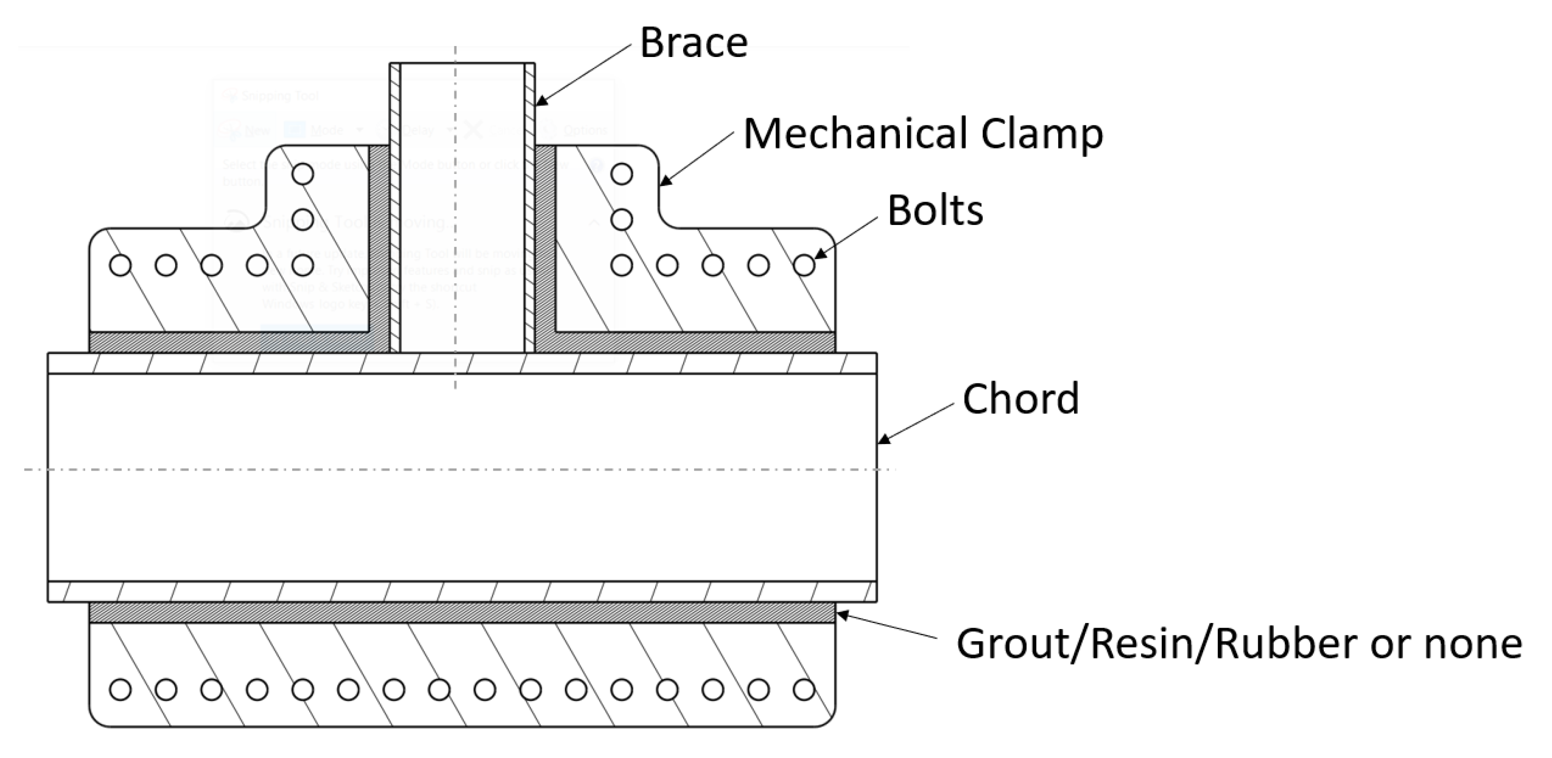
4.4. Mechanical Clamping

Mechanical clamping of an offshore joint involves connecting a new structure to an existing damaged or weak joint, as presented in Figure 8. Mechanical clamping has been shown to be a very adaptable rehabilitation technique. Generally, two specially designed joint-shaped halves are bolted to a joint to enhance and contribute to the load-bearing capacity of the joint. Clamps must be designed with extreme caution. A precise metrology survey is required to find the dimensions of the tubular joint, including the weld line details, dents, or ovalization. Different clamp configurations are employed depending on the load transfer mechanism, for example, stressed, unstressed or stressed grouted, and elastomer padded joint clamps.
The strength of a stressed clamped joint is derived from the clamp-to-joint friction (both steel) created by the tightening of bolts that results in compressive forces normal to the contact between the tubular joint and reinforcement clamp. Precise sizing of the clamp is required for stressed clamps. Clamps contribute to load bearing when bolts are appropriately stressed. However, offshore structures are subject to fatigue loading due to winds, waves, and water currents. The prestress in bolts is compromised, and corrosion deteriorates its performance over time. This option may be preferably employed as a short-term remedy until the next planned maintenance or shutdown when permanent rehabilitation options are applied.
On the other hand, an unstressed grouted clamp consists of a clamp around a tubular joint filled with some grout material. The bond between the grout and joint is responsible for load transfer. Less detailed sizing is required for unstressed clamps than for stressed clamps. A grouted clamp could be installed rapidly and relatively easily, allowing for substantial fit-up tolerances [17,18].
A grouted clamp is an effective tool for repairing damaged tubular joints, and it has been implemented on numerous offshore jacket platforms, specifically in underwater sections. Sometimes both prestress and grouting are combined in a single joint, combining both advantages. Stressed bolts ensure enhanced load transfer, whereas the cost of grout injection is paid to obtain the benefits of loose fit tolerances. The requirement for precise metrology is eliminated in rubber-padded clamps. Rubber-padded mechanical clamps are identical to stressed mechanical clamps, except that elastic padding is bonded between the clamp and joint to accommodate the deteriorations on the tubular joint surface.
Resin clamps are similar to grouted clamps but utilize resin instead of grout [16]. The benefit of a resin clamp is that resin has a significantly higher bond strength. The disadvantage is that the surface of the member must be treated before application. Most of these clamping options involve bolting, which may not be preferred for fatigue loading. The fatigue due to bolts is especially severe when the clamp is underwater. Moreover, bolted joints are prone to corrosion.

4.5. Stiffener Welding

Welding of stiffeners is a renowned solution to strengthen offshore joints. Welding has many challenges but is an efficient rehabilitation solution. Following are the different schemes for increasing the stiffness of tubular joints.

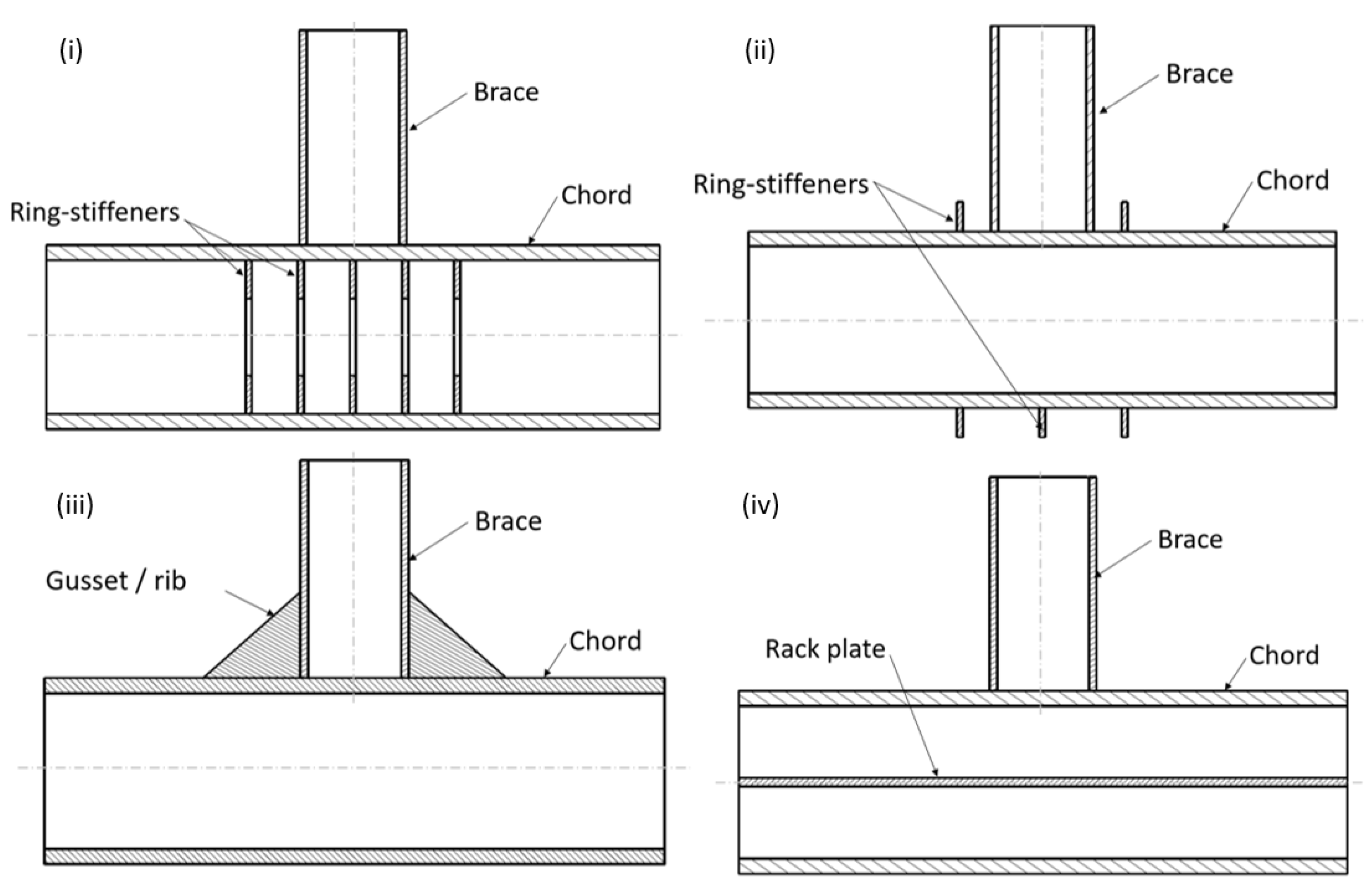
4.5.1. Welding Ring/Ribs

Stiffeners in the form of internal ring stiffeners, external ring stiffeners, ribs, gusset plates, rack plates, etc., can be welded to reinforce tubular joints. Some typical designs are shown in Figure 9. Adding internal ring stiffeners has been performed since the 1980s for structural enhancement of tubular joints as shown in Figure 9i. About 2000 internal ring stiffened joints were estimated to be operational in the North Sea alone before the start of the 21st century [19]. It is an acceptable method for enhancing strength and capacity to resist brace loads of tubular joints. Adequately positioned and sized internal ring stiffeners reduce stress concentration and improve stress distribution at the chord-brace interface. Various researchers have studied internal ring-stiffening of tubular joints using finite element analysis (FEA) and experimentally. Murthy et al. [20] investigated the effect of internal ring stiffeners in the chord of T and Y joints subjected to axial, in-plane bending, and out-of-plane bending load. Internal ring stiffeners were found to reduce the SCF for axial and out-of-plane by 36–70% and 13% for in-plane bending, increase the ultimate strength by 66–73%, and enhance fatigue life. Mathematical equations were also derived for the calculation of SCF in an internal ring stiffened T/Y-joint, and these expressions were validated experimentally. Lan et al. [21] investigated internal ring-stiffened DT joints loaded axially. Based on numerical findings and theoretical calculations, equations were proposed for calculating the static strength of DT joints subjected to axial compression and axial tension. Ahmadi et al. [22,23,24,25,26,27,28] investigated various design aspects of internal ring-stiffened KT-joints subjected to axial, in-plane, and out-of-plane bending loads. They compared SCF for cases with and without ring-stiffeners, and all cases reported a substantial reduction in SCF. Various equations were developed based on data obtained from numerical simulations and experimental investigations for SCF around the central and inclined brace–chord interface. Krishna and Nallayarasu [29] investigated the effect of internal ring stiffeners and proposed mathematical equations for estimating SCF at the brace–ring interface. Besides their proven advantages, applying internal ring stiffeners may have some practical implications. The diameter of the chord should be large enough to allow access to welding internal ring stiffeners; otherwise, this method is unsuitable. Furthermore, installing internal ring stiffeners in an existing operational structure is very complicated.
On the contrary, external ring stiffening can be easily applied to erected structures. It can significantly enhance the axial and out-of-plane load capacity of a joint. A parametric study of an X-joint reinforced with external ring stiffeners showed strength enhancement up to twice the original joint strength [30]. A typical T-joint strengthened with three external ring stiffeners is shown in Figure 9ii. Gussets/ribs are used for enhancement in in-plane load capacity. Various configurations of ribs can be applied to tubular joints based on the geometry and load requirement. A typical T-joint reinforced with triangular ribs is shown in Figure 9iii. Rack plates were investigated for enhancement in in-plane load capacity. Continuous or segregated rack plates can shift and reduce hotspot stress. Woghiren and Brennan [31] analyzed the muti-planar tubular KK joints reinforced by rack plate stiffeners and found a reduction in SCF and enhancement in fatigue life. The hotspot stress region can be transferred by incorporating a rack plate stiffener to a location with easy access for nondestructive testing (NDT). Parametric equations were derived using regression analysis to calculate the SCF and the probable location of fatigue crack initiation. A typical rack plate installed at the chord center of a T-joint is shown in Figure 9iv. The studies highlighted here show the effectiveness of stiffener welding for various joint types.

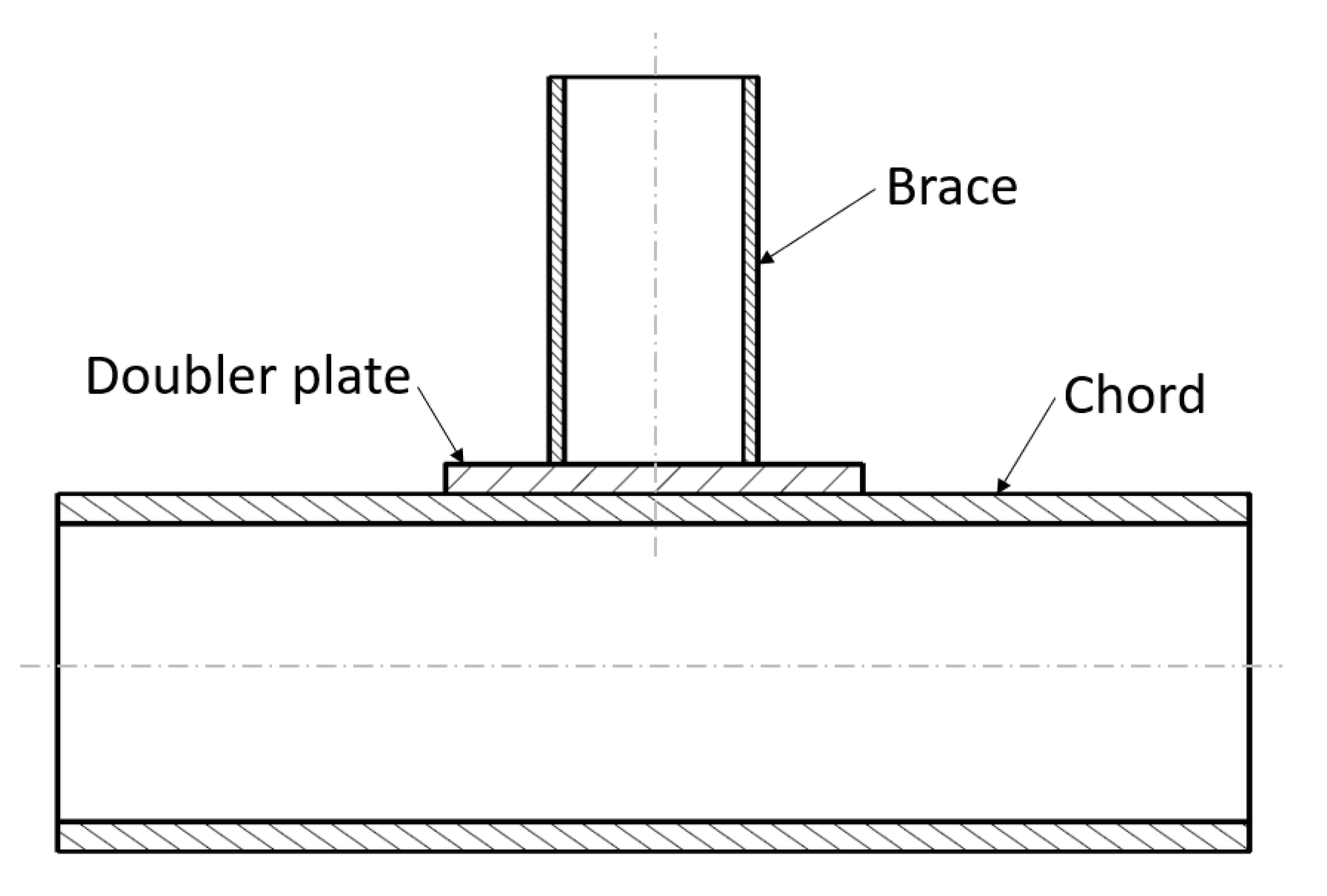
4.5.2. Welding Doubler Plate

A doubler plate is a plate welded to the chord using fillet welding to increase its thickness locally. The brace is then welded to the plate using fillet welding, as shown in Figure 10. A doubler plate can strengthen a joint that needs reinforcement or additional load capacity to resist punching shear stress. Fung et al. [32,33] studied the maximum capacity of a doubler plate-reinforced T-joint and found that the doubler-plated configuration resisted axial compression and tension, in IPB and OPB efficiently. The length of the doubler plate and brace angle were found to have little effect on the final capacity, with the brace-to-chord thickness ratio significantly affecting load capacity enhancement. Hoon et al. [34] tested a doubler-plate-reinforced tubular T-joint under combined loads. They found that hotspot stress shifted from the chord–brace interface to the brace–doubler plate interface, and SCF was reduced due to doubler plate incorporation at a tubular joint.
Choo et al. [35,36] investigated tubular joints with and without doubler plate reinforcement and reported a strength enhancement of up to 200 percent for tubular X joints subjected to IPB. Feng et al. [37] investigated the static compressive strength enhancement by doubler-plate in Y joints computationally and demonstrated the effectiveness of this method. Nazari et al. [38] presented a set of parametric equations to facilitate the calculation of SCFs for T, Y, K, X, and DT tubular joints reinforced with doubler plates. Based on sensitivity analysis, the SCF is most sensitive to the parameters (d/D and t/T). Recent research by Nassiraei et al. [39], who analyzed the static performance of T/Y joints subjected to tension and compressive brace loading, found that the doubler plate could significantly enhance the stiffness and ultimate load capacity. Soh [40] investigated the stress concentration factors in doubler plate-reinforced tubular joints, covering the four fundamental loading types (axial tension, axial compression, IPB, OPB). However, it was found that the doubler plate-reinforced tubular joint would be more prone to fatigue failure compared to unreinforced tubular joints under axial tension and bending.

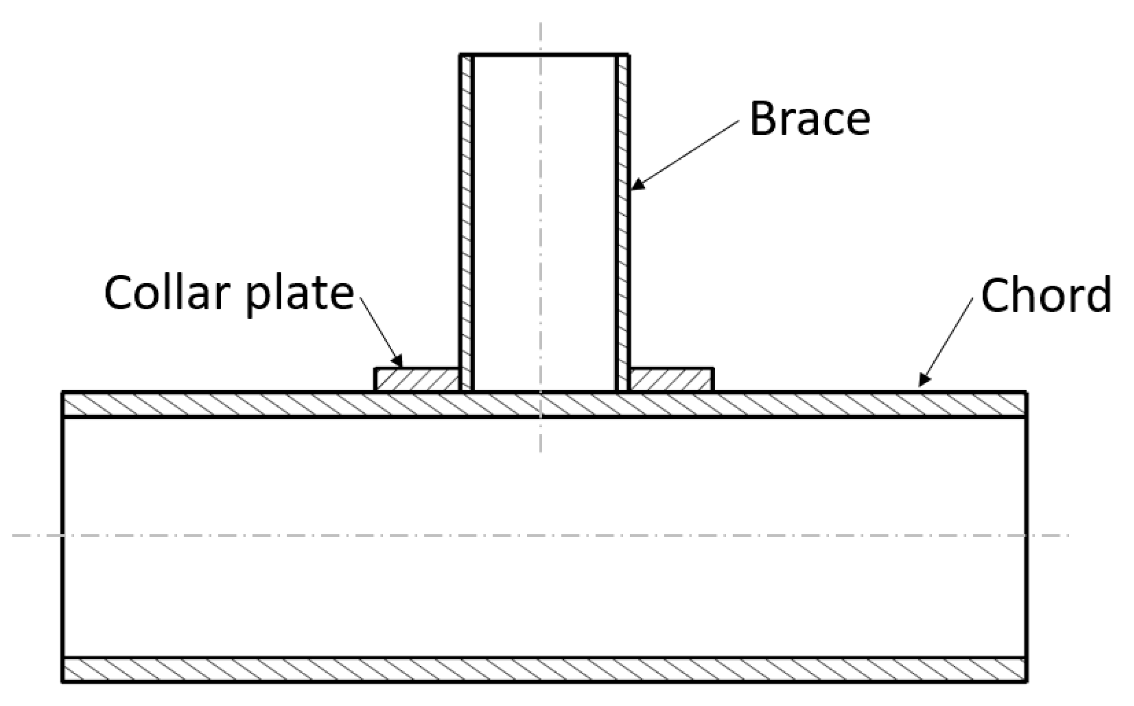
4.5.3. Welding Collar Plate

In the case of a collar plate, the brace is directly welded to the chord, and an additional plate is welded to both brace and chord using fillet welding, as shown in Figure 11. Shao et al. [41] found that T-joint specimens with collar-plate reinforcement could dissipate more energy before failure when subjected to cyclic loading than unreinforced specimens. Collar plate-reinforced tubular T-joints were analyzed experimentally and numerically. It was concluded that the collar plate would shift the hotspot stress location from the brace–chord intersection of the unreinforced specimens to the weld toe at the chord–collar interface. Nassiraei et al. [42] studied the static strength and structural behavior of tubular T/Y-joints with collar plates under brace compressive loading. The effect of joint geometry and collar plate size on ultimate strength and failure mode was investigated. Up to 270% enhancement in strength by incorporation of a collar plate was reported. The length of collar plate was found to be more effective in enhancing ultimate strength than the thickness of collar plate. A parametric equation was proposed for the strength prediction of collar plate-reinforced T/Y-joint based on a series of FE models. Numerical and mathematical models were validated with experimentation.
There are many similarities between doubler plates and collar plates. The fundamental mechanism of both methods is to increase the thickness of the chord at the intersection. These two methods are incredibly economical. However, the reinforcement may not be effective if the tubular joint is subject to out-of-plane bending. Moreover, adding a doubler plate to an in-service joint will require the disassembly of the brace from the chord, which may not be easily manageable.

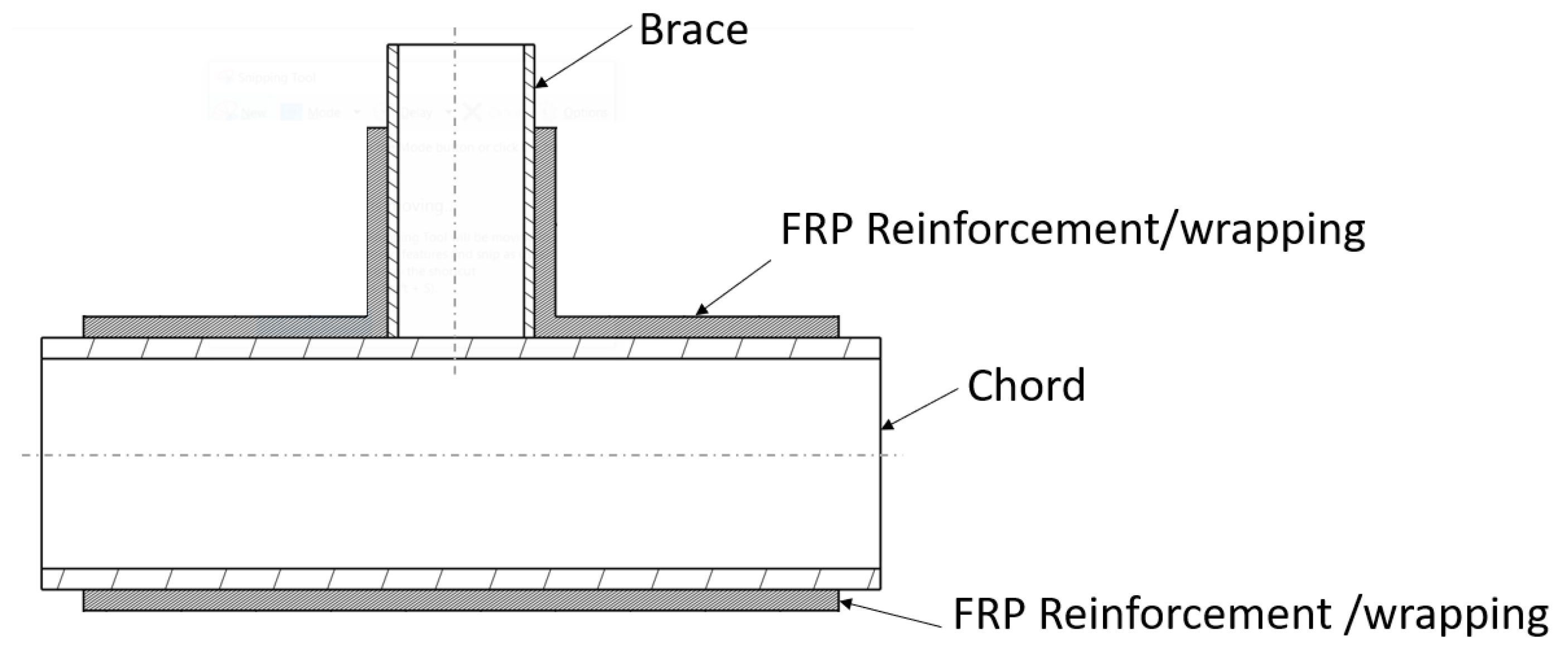
4.6. Composites Reinforcement

Fiber-reinforced polymers (FRP) composite reinforcement has been successfully used over the past three decades in bridges, beams, and columns, with significant reinforcing capacity. Researchers have gradually introduced FRP composites to offshore structures in recent years. Recent versions of widely acceptable codes and standards, such as ASME PCC-2 [43] and ISO 24,817 [44], consider composite reinforcement a legitimate repair method for offshore structures. FRP repair has more benefits than the welding method [45]. FRP composite repair provides safety, ease of application, applicability without hot work, and high ultimate strength. A single FRP material can be designed for vast specific strength/stiffness requirements and can be applied to complex shapes/profiles, even with limited accessibility [13]. Numerous researchers have investigated the rehabilitation of tubular joints using FRPs, yet these studies are limited to elementary joint types and load cases. A conceptual scheme of FRP reinforcement for a typical T-joint is illustrated in Figure 12.
Amongst various structural composites, glass fiber-reinforced polymer (GFRP) and carbon fiber-reinforced polymer (CFRP) are widely used for structural rehabilitation. Pantelides et al. [46] investigated the repair of cracked truss joints using GFRP composites. Their experimental results revealed that the GFRP composite could enhance the load capacity of joints having cracks of 24–66% of the total weld length by 17–25% times that of connection with no cracks. It was also concluded that GFRP reinforcement did not significantly increase joint stiffness but increased its strength. Lesani et al. [47,48] conducted a series of investigations on GFRP-reinforced tubular T and Y-joints subjected to axial compressive loads. It was reported that the ultimate joint capacity of FRP-reinforced joints increased by 22–66%, depending on the degree of reinforcement. The excellent correlation between numerical (FEA) and experimental results showed a perfect bond between FRP and steel employed in FEA. Fam et al. [49] investigated GFRP and CFRP reinforcement of K-joints and concluded that CFRP performed better than GFRP. Fam reported enhanced fatigue life for CFRP rehabilitated joints than joints without cracks. Karbhari et al. [50] recommended glass and carbon hybrid reinforcement to avoid galvanic corrosion. Fu et al. [51] investigated the application of CFRP on undamaged tubular K-joints using experimental and finite element methods. It was revealed that CFRP reinforcement could postpone the dominant failure mode of chord plastic deformation and chord punching shear because the governing failure nodes were successfully inhibited but not stopped. In addition, initial stiffness and ultimate load capacity were substantially increased. The load capacity of K-joints was significantly improved by both bidirectional and unidirectional CFRP reinforcement.

4.6.1. Composites Reinforcement in the Underwater Environment

Joints of offshore structures can be wholly submerged in the sea or partially exposed to water in the splash zone. Conventional strengthening solutions have become very expensive and retrofitting using fiber reinforced polymers (FRPs) can be an economical alternative in such a scenario. The structural and physical behavior of composites is more complex in the aquatic medium than for polymer alone. There is still a lack of confidence in applying FRP repair to underwater structures [52] as the properties of FRP can be affected by environmental factors. The matrix primarily governs the underwater performance of FRP. Debonding and delamination are common failure modes in FRP-reinforced steel structures. Selecting suitable adhesives for underwater applications is an important parameter in improving the performance of FRP repair [53]. The strength and stiffness of the epoxy/adhesive generally degrade due to environmental conditions [50,54,55]. For sustained load-bearing capacity by FRP reinforcement, the adhesive must be able to transfer loads from the structure to FRP. Preferably, the failure of the adhesive should occur after the fibers rupture [56]. Exposure to seawater or cold/hot weather reduces the ductility and bond strength between FRPs and the underlying steel structure. The joint between steel and FRPs is also severely affected by water penetration, probably through diffusion, absorption, or capillary action [55]. This penetration can reduce the strength and stiffness of reinforced members.
Seica and Packer [57] experimentally investigated FRP reinforcement to repair tubular steel members using the bend test. Beam samples were prepared both above and under the water. It was concluded that CFRP could be used to rehabilitate underwater structures. However, underwater curing, compared to in-air curing, resulted in a reduction in strength. Only flexural stresses were assessed in this study, and aging effects were not investigated. Saeed [58] investigated the effects of underwater curing of GFRP and epoxy. GFRP samples were cured both above and under the water. Relatively reduced tensile strength, modulus, and maximum strain were reported for underwater cured samples. Guo et al. [59] performed an immersion test of CFRP and GFRP samples for 120 days in deionized water at 40 °C, 60 °C, and 80 °C. They investigated the effects of water immersion on physical, thermal, and mechanical properties. Short beam shear strength (SBSS) at 40 °C, 60 °C, and 80 °C was 95.68%, 91.44%, and 87.98% for CFRP, and 86.33%, 81.38%, and 76.88% for GFRP after 120 days of water immersion. Three-point bending strength (TPBS) at 40 °C, 60 °C, and 80 °C was 92.37%, 90.31%, and 87.00% for CFRP, and 92.11%, 86.71%, and 74.17% for GFRP after 120 days of water immersion.
George et al. [52] experimentally investigated the behavior of underwater and in-air repaired CHS pipes. Corrosion was simulated as a reduction in thickness by machining. The effect of concentric and eccentric axial loading was investigated. CFRP was used for repair in both mediums (air and water). Reduced recovery of ultimate strength was recorded for the underwater repair compared to conventional in-air repair. The recorded energy absorption for underwater repair was superior to that of corroded but inferior to in-air repair. This study was limited to simple pipes under axial compressive load. It was concluded that underwater repair using FRP is an effective alternative to the conventional method. George [60] investigated ductility, energy absorption, strain, and displacement behavior of underwater FRP repair of 20% corroded pipe subjected to compression load. Corrosion was induced by removing 20% thickness in the middle of the pipe through machining. Pipes were reinforced with one layer of glass and two layers of CFRP, both in the air and underwater. Slightly inferior ultimate strength was reported for underwater samples. However, stiffness was comparable for all samples. Finite element analysis was used to validate the experimental study.
Karbhari [61] investigated wet layup CFRP immersed for 44 months. Single and double-layer specimens were immersed in deionized water at 23 °C, 37.8 °C, and 60 °C. Reference samples were placed in a controlled environment at 23 °C and 30% relative humidity. Variations in physical properties and modulus were measured using dynamic mechanical thermal analysis (DMTA). It was reported that degradation effects are lower than those predicted through short-term exposures. It was inferred that the rate of change in modulus, glass transition, and moister absorption in short-term immersion substantially reduces after a threshold is reached. This reduced rate then dominates in long-term immersion.
Xian et al. investigated the simultaneous bending load and water immersion. It was revealed that a higher bending load would favor the formation of microcracks. This will promote hydrolysis, plasticization, and debonding at the resin–fiber interface. A strength reduction of more than 50% was reported for 360 days of water immersion [62].

4.6.2. Techniques of Composite Repair

Composite materials are a combination of high-strength fibers embedded in a polymer matrix. The fibers take load while the matrix transfer load between fibers and from the joint to the reinforcement layers. Most FRP repair options are proprietary systems, and limited technical information is available. FRP repair methods include precured layers, clamps, flexible wet layup, pre-impregnated, split composite sleeves, flexible tape, and many more [63]. Each of these options has some strengths and limitations. Based on a broad classification, these repair solutions are briefly discussed below.

Precured Layered System

Precured FRP composites are applied using a field-adhesive to adhere to the repaired joint. Commercially available multilayer solutions used in the offshore repair industry include Clock Spring [64], PermaWrap [65], and WeldWrap [66]. Precured layered repair uses a prefabricated laminate of a high-strength composite material in a controlled factory environment. The laminate layers are sealed together using an effective interlayer bonding adhesive and wrapped around the joint tightly with epoxy. High-compressive strength infill material (primer) is applied in the damaged area before installation to help with load transfer, such as in corrosion pits or cracks. Precured systems have an identical drawback as steel sleeve/clamp repairs in that these are only available for simplified joints.
Composite sleeves are a particular category of precured system, similar to the metallic clamps but have various advantages over the metallic clamps. The composite sleeve can employ adhesive joining and conventional bolting simultaneously and is used for heavy-duty repair. This option was applied to rehabilitate underwater piles at the Missingham Bridge in Australia in 2005 [67]. This solution was investigated at the University of Southern Queensland and was found effective in rehabilitation. Split composite sleeves are superior to pre-impregnated, flexible layup, and precured multilayer systems, with the composite sleeve being a permanent repair solution. Alexander [68] discovered that carbon half-shell split sleeves could be utilized well for high-pressure pipe repair. PETRONAS recently patented its pipeline repair clamp, ProAssure Clamp [69]. The current application of clamps is limited to straight pipe sections only. Its use for bend sections and complex joints has yet to be explored.

Pre-Impregnated System

The pre-impregnation of FRPs employs a factory-controlled wet-out method to achieve uniform resin content and maximum and repeatable characteristics. Pre-impregnated systems such as ProAssure Wrap Extreme [70], Syntho-Glass XT [71], and Viper-Skin [72] are some examples of repair systems utilized for offshore structures. ProAssure Wrap Extreme is an innovative composite resin technology for onshore and offshore repair developed by CSIRO (Commonwealth Scientific and Industrial Research Organization) and PETRONAS (Petroliam Nasional Berhad). ProAssure Wrap Extreme consists of E-glass fiber and a unique epoxy resin. The repair system is curable underwater and resistant to humid environments, with little loss of adhesion and mechanical properties. Syntho-Glass XT and Viper-Skin are both products of NRI (Neptune Research Incorporation). Syntho-Glass is based on bidirectional fiberglass, whereas Viper-Skin is a biaxial hybrid of carbon and glass fibers. Both are pre-impregnated with polyurethane resin. Pre-impregnated systems are flexible and can conform to complex joints. In contrast to the wet layup technology, pre-impregnated FRPs must be stored at a controlled temperature and humidity. The requirement of a stringent storage environment (usually sub-zero °C) makes this option very difficult for offshore applications.

Flexible Wet Layup System

The offshore industry widely utilizes flexible wet layup technology for pipes and joints [73]. Aquawrap [74], RES-Q Composite Wrap [75], Armor Plate [76], and R4D-S [77] are examples of wet layup technologies that are commercially available. Many non-proprietary wet lay systems have also been used. Flexible wet layup utilizes a resin matrix uncured during application. FRP impregnated with the resin is applied to reinforce the area where strength, stiffness, or load capacity enhancement is required. After curing, the uncured epoxy forms a stiff shell and efficiently contributes to load transfer from the structure to FRPs and between FRP layers. The Aquawrap repair system comprises polyurethane epoxy with biaxial glass (Aquawrap-G03 and G05) and carbon (Aquawrap C-2) FRPs. It has been reported that this method is user-friendly, dependable, and effective for recovering pipe that has sustained various types of damage. The Armor Plate system is an E-glass/epoxy material impregnated with several resin systems to suit different environmental conditions, including underwater and a broad temperature range (−51 to 91 °C). Alexander et al. [78] presented their test findings and field experience with the Armor Plate system.
Similarly, Worth [76] carried out testing with Armor Plate. Damaged and corroded pipes were repaired and subjected to cyclic stress testing, an effective way to recover mechanically damaged pipe structures and prolong their fatigue life. Morton [79] reported the feasibility of a CFRP-based composite wrap called RES-Q and a proprietary epoxy resin. RES-Q can be applied to various structural and process pipes. Besides CFRP and GFRP, aramid composites are also successfully utilized to reinforce steel structures. R4D-S (REINFORCEKiT 4D SUBSEA) is a wet layup system composed of unidirectional Kevlar FRP and subsea curing resin [80]. The unique resin composition offers superior abrasion, chemical, and moisture resistance. R4D-S is wrapped around the damaged pipe segment to enhance its load capacity. However, it is generally understood that aramid and natural fibers are susceptible to moisture-related degradation [81].
No strict storage conditions are required for flexible wet layup reinforcement materials. Besides the applicability to reinforcing complex shaped joints and regions of limited access, the wet-layup process is challenging to install due to the in situ curing of the resin. Under-curing and non-uniform curing can occur when the rehabilitated joint is underwater, specifically when the water table is high. Under-curing can reduce the load-bearing ability of adhesives; hence, the overall strength of the repair is compromised, as documented in some studies [75,82].

4.6.3. Summary of FRP Reinforcement

The high specific strength and modulus make FRP an efficient joint reinforcement technique. No requirement of hot work makes this option feasible for offshore operations. The relatively low density of FRP will have little weight effect on the original structure. The composite repair can strengthen complex geometries on-site. In addition, adaptability to any complex shape and areas of limited access make FRP rehabilitation an excellent choice for joint repair. A single FRP material can be designed to rehabilitate various joints by varying the number of layers and their orientation; hence, there is no need to maintain any extensive inventory of repair materials. Composite reinforcements can enhance the load capacity of joints subjected to axial, in-plane, or out-of-plane bending. Various companies have developed epoxies for underwater use, with expert divers making the repairs to underwater structures using FRP composites. The composite repair was traditionally considered a temporary solution, implemented as an interim remedy until the next interruption. Until 2015, there was no accepted inspection technique for bonds when an ISO standard covered this topic. ASME PCC-2 [43], ISO 24,817 [44], and DNVGL-RP-C301 [83] have since covered the entire repair system, including the composite laminates, surface preparation, and fillers. The economics of FRP repair necessitates that the laminate/layup be adequately engineered.
The employed composite for repair can be broadly categorized into precured, pre-impregnated, and flexible wet layup systems. Each of these has various advantages over the other. Precured systems can be quickly applied using bolting and interface epoxies/adhesives. Pre-impregnated systems are semi-finalized in the control environment of the factory and hence offer substantially good mechanical behavior. Flexible wet layup benefits from curing at room temperature as well as underwater. The choice of composite system should be based on the practical applicability, skills of manpower, and criticality of the joint being rehabilitated.
Interface bond is the key parameter for the effective repair of joints using FRP. Adequate surface preparation also plays a vital role in the effectiveness of the bond between joint and composite reinforcement and can eliminate the chances of interfacial delamination. However, the bond mechanism of the reinforcing systems to tubular joints has not been examined in detail. The long-term behavior of composite reinforcement in aquatic and humid environments is a rarely explored avenue. Various repair solution providers claim sustainability of their products for a substantial time duration of up to 20 years. However, research is still minimal to validate such claims. Phenomena such as water absorption, diffusion, osmosis, swelling, blistering, and plasticization and their effects on the mechanical properties of composites are not fully understood [81]. The coupling effects of hydrostatic pressure, temperature, mineral concentration, fouling, water currents, and biological growth on the physical and mechanical behavior of composite reinforcement also require investigation.
Furthermore, the fabrication method substantially impacts the mechanical properties of composites. A composite rehabilitation method that is possible in the laboratory may not always be as effective in practice. Therefore, the process and environmental variables in the laboratory should be replicated as closely as possible to ensure that the laboratory results represent the real-world scenario. The fabrication parameter should be optimized to tackle issues such as fiber misalignment, waviness, wrinkles, voids, delamination, low fiber volume fraction, uneven curing, and other similar defects. A thorough inspection should be carried out to ensure the reliability of reinforcement after curing. Unlike single-phase materials, a visual inspection can be very limited regarding the state of the internal structure of composite reinforcement. Pulsed eddy current, dynamic response spectroscopy, radiography, and sensors placed between the FRP and joint (live monitoring) are being researched to inspect composite structures above and under the water. The initiation and growth of cracks in thick marine composite laminates have not been explored in as much detail as that in thin laminates and metallic structures. The laboratory results of thin laminates may not be transferrable by “scaling factor” alone, as new failure modes can occur [81]. Besides all these, it is well understood that the FRP utilization for the reinforcement of tubular members and joints will further increase in the future.

5. Summary of Rehabilitation Methods

Rehabilitation methods for damaged or aged offshore joints have been discussed in detail. The selection of a particular rehabilitation strategy must be thoroughly examined. The nature of the damage and loads on a joint play a significant role in this selection. Table 2 presents a subjective assessment of the effectiveness of different rehabilitation techniques for certain applications. The efficacy of specific techniques, cost, installation time, and available technical expertise should also be considered. These characteristics of different rehabilitation methods are presented in Table 3. This comparison is based on subjective assessment by the authors. Clamping of pipelines can be quick but may require heavy machinery. Welding stiffeners involve hot work and may not be permitted sometimes. In many circumstances, fiber-reinforced polymers (FRP) can be preferred alternatives for rehabilitation. FRP repair of tubular joints has several advantages over other methods. However, research on FRP materials, epoxies, methods of composite reinforcement, curing of composite, especially in the underwater environment, and ways to improve the interface bond between the metal and composite needs further exploration. Investigations on the long-term performance and post-cure inspections will impart confidence to use composite reinforcement to repair critical joints permanently.

Author Contributions

Conceptualization, S.K. and M.I.; software, M.I. and A.R.; writing—original draft preparation, M.I.; writing—review and editing, S.K, M.I., V.P., and M.O.; supervision, S.K. and V.P.; project administration, S.K.; funding acquisition, S.K. All authors have read and agreed to the published version of the manuscript.

Funding

This research received funding from Yayasan Universiti Teknologi PETRONAS under grant No. 015LC0-443.

Institutional Review Board Statement

Not applicable.

Informed Consent Statement

Not applicable.

Data Availability Statement

Not applicable.

Acknowledgments

The authors gratefully acknowledge the constructive comments of anonymous reviewers on the draft version of this paper.

Conflicts of Interest

The authors declare no conflict of interest.

References

  1. Saini, D.S.; Karmakar, D.; Ray-chaudhuri, S. A review of stress concentration factors in tubular and non-tubular joints for design of offshore installations. J. Ocean Eng. Sci. 2016, 1, 186–202. [Google Scholar] [CrossRef] [Green Version]
  2. Ávila, B.V.; Correia, J.; Carvalho, H.; Fantuzzi, N.; De Jesus, A.; Berto, F. Numerical analysis and discussion on the hot-spot stress concept applied to welded tubular KT joints. Eng. Fail. Anal. 2022, 135, 106902. [Google Scholar] [CrossRef]
  3. Corigliano, P.; Crupi, V. Review of Fatigue Assessment Approaches for Welded Marine Joints and Structures. Metals 2022, 12, 1010. [Google Scholar] [CrossRef]
  4. Nichols, N.W.; Khan, R. Structural integrity management system (SIMS) implementation within PETRONAS’ operations. J. Mar. Eng. Technol. 2015, 14, 61–69. [Google Scholar] [CrossRef] [Green Version]
  5. Gao, H.; Jiao, X.; Zhou, C.; Shen, Q.; Yu, Y. Study on remote control underwater welding technology applied in nuclear power station. Procedia Eng. 2011, 15, 4988–4993. [Google Scholar] [CrossRef] [Green Version]
  6. Pai, K. Braced Cofferdam—Uses and Types. The Constructor. 2023. Available online: https://theconstructor.org/building/formwork-shuttering/braced-cofferdam/40272/ (accessed on 26 November 2022).
  7. Wang, Z.; Yang, K.; Chen, M.; Lu, Y.; Wang, S.; Wu, E.; Bi, K.; Ni, Z.; Sun, G. Surface & Coatings Technology High-quality remanufacturing of HSLA-100 steel through the underwater laser directed energy deposition in an underwater hyperbaric environment. Surf. Coatings Technol. 2022, 437, 128370. [Google Scholar] [CrossRef]
  8. Fischer, K.P. A Review of Offshore Experiences with Bolts and Fasteners. In Proceedings of the CORROSION 2003 Research Topical Symposium: Modeling and Prediction of Lifetimes for Corrodible Structures, San Diego, CA, USA, 16 March 2003. [Google Scholar]
  9. Muzghi, I.A. Fastener Corrosion in Arabian Gulf Offshore Installations. 2004; pp. 1–5. Available online: https://www.osti.gov/etdeweb/servlets/purl/20671830 (accessed on 26 November 2022).
  10. Mehmanparast, A.; Lotfian, S.; Vipin, S.P. A review of challenges and opportunities associated with bolted flange connections in the offshore wind industry. Metals 2020, 10, 732. [Google Scholar] [CrossRef]
  11. Lochan, S.; Mehmanparast, A.; Wintle, J. A review of fatigue performance of bolted connections in offshore wind turbines. Procedia Struct. Integr. 2019, 17, 276–283. [Google Scholar] [CrossRef]
  12. McGeorge, D.; Echtermeyer, A.T.; Leong, K.H.; Melve, B.; Robinson, M.; Fischer, K.P. Repair of floating offshore units using bonded fibre composite materials. Compos. Part A Appl. Sci. Manuf. 2009, 40, 1364–1380. [Google Scholar] [CrossRef]
  13. Perrut, V.A.; Meniconi, L.C.D.M.; Sampaio, E.M.; Rohem, N.R.F.; da Costa, M.F. Fatigue and quasi-static analysis of a new type of surface preparation used for the CFRP repair of steel offshore structures. J. Adhes. 2018, 95, 849–873. [Google Scholar] [CrossRef]
  14. Yang, M.; Kainuma, S.; Xie, J.; Liu, W.; Liu, Y. Bond behavior between CFRP and corroded steel plate associations with surface treatments. Compos. Part B Eng. 2022, 246, 110280. [Google Scholar] [CrossRef]
  15. Lim, K.S.; Azraai, S.N.A.; Noor, N.M.; Yahaya, N. An Overview of Corroded Pipe Repair Techniques Using Composite Materials. Int. J. Mater. Met. Eng. 2016, 10, 19–25. [Google Scholar] [CrossRef]
  16. Souza, M.; Bayazitoglu, Y.; Lu, L.S.; Valdes, V.; Vazquez, R. Repairs of hurricane damaged platforms in the Bay of Campeche. In Proceedings of the Offshore Technology Conference, Houston, TX, USA, 4–7 May 1998; Volume 3, pp. 107–116. [Google Scholar] [CrossRef]
  17. Murphy, F.; Smith, B.L. The Investigation and Repair of Defective Joints on the Kinsale Alpha Platform. In Proceedings of the Offshore Technology Conference, Houston, TX, USA, 3–6 May 1993; pp. 143–153. [Google Scholar]
  18. Turner, J.W.; Wisch, D.J.; Guynes, S.J. A review of operations and mitigation methods for offshore platforms. In Proceedings of the Offshore Technology Conference, Houston, TX, USA, 2–5 May 1994; pp. 179–187. [Google Scholar] [CrossRef]
  19. Gandhi, P.; Raghava, G.; Murthy, D.S.R. Fatigue Behavior of Internally Ring-Stiffened Welded Steel Tubular Joints. J. Struct. Eng. 2000, 126, 809–815. [Google Scholar] [CrossRef]
  20. Murthy, D.S.R.; Rao, A.G.M.; Gandhi, P.; Pant, P.K. Structural efficiency of internally ring-stiffened steel tubular joints. J. Struct. Eng. 1992, 118, 3016–3035. [Google Scholar] [CrossRef]
  21. Lan, X.; Wang, F.; Ning, C.; Xu, X.; Pan, X.; Luo, Z. Strength of internally ring-stiffened tubular DT-joints subjected to brace axial loading. J. Constr. Steel Res. 2016, 125, 88–94. [Google Scholar] [CrossRef]
  22. Ahmadi, H.; Zavvar, E. Stress concentration factors induced by out-of-plane bending loads in ring-stiffened tubular KT-joints of jacket structures. Thin-Walled Struct. 2015, 91, 82–95. [Google Scholar] [CrossRef]
  23. Ahmadi, H.; Mohammadi, A.H.; Yeganeh, A. Probability density functions of SCFs in internally ring-stiffened tubular KT-joints of offshore structures subjected to axial loading. Thin-Walled Struct. 2015, 94, 485–499. [Google Scholar] [CrossRef]
  24. Ahmadi, H.; Yeganeh, A.; Mohammadi, A.H.; Zavvar, E. Probabilistic analysis of stress concentration factors in tubular KT-joints reinforced with internal ring stiffeners under in-plane bending loads. Thin-Walled Struct. 2016, 99, 58–75. [Google Scholar] [CrossRef]
  25. Ahmadi, H.; Lotfollahi-Yaghin, M.A. Stress concentration due to in-plane bending (IPB) loads in ring-stiffened tubular KT-joints of offshore structures: Parametric study and design formulation. Appl. Ocean Res. 2015, 51, 54–66. [Google Scholar] [CrossRef]
  26. Ahmadi, H.; Lotfollahi-Yaghin, M.A.; Yong-Bo, S. Chord-side SCF distribution of central brace in internally ring-stiffened tubular KT-joints: A geometrically parametric study. Thin-Walled Struct. 2013, 70, 93–105. [Google Scholar] [CrossRef]
  27. Ahmadi, H.; Lotfollahi-Yaghin, M.A. Experimental and Numerical Investigation of Geometric SCFs in Internally Ring-Stiffened Tubular KT-Joints of Offshore Structures. J. Persian Gulf 2013, 4, 1–12. [Google Scholar]
  28. Ahmadi, H.; Lotfollahi-Yaghin, M.A.; Yong-Bo, S.; Aminfar, M.H. Parametric study and formulation of outer-brace geometric stress concentration factors in internally ring-stiffened tubular KT-joints of offshore structures. Appl. Ocean Res. 2012, 38, 74–91. [Google Scholar] [CrossRef]
  29. Krishna, G.C.S.; Nallayarasu, S. Experimental and numerical investigation on stress concentration at brace-ring intersection (BRI) of internally ring stiffened tubular T-joints. Appl. Ocean Res. 2022, 126, 103288. [Google Scholar] [CrossRef]
  30. Melek, P.G.; Gaawan, S.; Osman, A. Strengthening Steel CHS X-Joints Subject to Compression by Outer Ring stiffeners. Int. J. Steel Struct. 2020, 20, 1115–1134. [Google Scholar] [CrossRef]
  31. Woghiren, C.O.; Brennan, F.P. Weld toe stress concentrations in multi-planar stiffened tubular KK joints. Int. J. Fatigue 2009, 31, 164–172. [Google Scholar] [CrossRef] [Green Version]
  32. Fung, T.C.; Soh, C.K.; Chan, T.K.; Erni. Stress Concentration Factors of Doubler Plate Reinforced Tubular T Joints. J. Struct. Eng. 2002, 128, 1399–1412. [Google Scholar] [CrossRef]
  33. Fung, T.C.; Chan, T.K.; Soh, C.K. Ultimate Capacity of Doubler Plate-Reinforced Tubular Joints. Available online: https://ascelibrary.org/doi/10.1061/%28ASCE%290733-9445%281999%29125%3A8%28891%29 (accessed on 26 November 2022).
  34. Hoon, K.; Wong, L.; Soh, A. Experimental investigation of a doubler-plate reinforced tubular T-joint subjected to combined loadings. J. Constr. Steel Res. 2001, 57, 1015–1039. [Google Scholar] [CrossRef]
  35. Choo, Y.S.; Van der Vegte, G.J.; Zettlemoyer, N.; Li, B.H.; Liew, J.Y.R. Static Strength of T-Joints Reinforced with Doubler or Collar Plates. I: Experimental Investigations. J. Struct. Eng. 2005, 131, 129–138. [Google Scholar] [CrossRef]
  36. Choo, Y.S.; Liang, J.X.; Van Der Vegte, G.J.; Liew, J.Y.R. Static strength of doubler plate reinforced CHS X-joints loaded by in-plane bending. J. Constr. Steel Res. 2004, 60, 1725–1744. [Google Scholar] [CrossRef]
  37. Qi, F.; Jia-Hua, T. The ultimate strength of doubler plate reinforced Y-joints under compression loading. J. Mar. Sci. Appl. 2005, 4, 13–19. [Google Scholar] [CrossRef]
  38. Nazari, A.; Guan, Z.; Daniel, W.J.T.; Gurgenci, H. Parametric Study of Hot Spot Stresses around Tubular Joints with Doubler Plates. Pract. Period. Struct. Des. Constr. 2007, 12, 38–47. [Google Scholar] [CrossRef]
  39. Nassiraei, H.; Lotfollahi-Yaghin, M.A.; Ahmadi, H. Static performance of doubler plate reinforced tubular T/Y-joints subjected to brace tension. Thin-Walled Struct. 2016, 108, 138–152. [Google Scholar] [CrossRef]
  40. Soh, A.-K.; Soh, C.-K. Stress analysis of axially loaded T tubular joints reinforced with doubler plates. Comput. Struct. 1994, 55, 141–149. [Google Scholar] [CrossRef]
  41. Yong-Boa, S.; Seng-Tjhenb, L.; Sing-Pingb, C.; Yan-Qing, C. Hysteretic performance of circular hollow section tubular joints with collar-plate reinforcement. J. Constr. Steel Res. 2011, 67, 1936–1947. [Google Scholar] [CrossRef]
  42. Nassiraei, H.; Lotfollahi-Yaghin, M.A.; Ahmadi, H. Static strength of collar plate reinforced tubular T/Y-joints under brace compressive loading. J. Constr. Steel Res. 2016, 119, 39–49. [Google Scholar] [CrossRef]
  43. ASME PCC-2; Repair of Pressure Equipment and Piping. American Society of Mechanical Engineers: New York, NY, USA, 2011.
  44. ISO 24817:2015; Petroleum, Petrochemical and Natural Gas Industries—Composite Repairs of Pipework—Qualification and Design, Installation, Testing and Inspection. ISO: Geneva, Switzerland, 2017.
  45. De Barros, S.; Banea, M.D.; Budhe, S.; De Siqueira, C.E.R.; Lobão, B.S.P.; Souza, L.F.G. Experimental analysis of metal-composite repair of floating offshore units (FPSO). J. Adhes. 2017, 93, 147–158. [Google Scholar] [CrossRef]
  46. Pantelides, C.P.; Nadauld, J.; Cercone, L. Repair of Cracked Aluminum Overhead Sign Structures with Glass Fiber Reinforced Polymer Composites. J. Compos. Constr. 2003, 7, 118–126. [Google Scholar] [CrossRef]
  47. Lesani, M.; Bahaari, M.R.; Shokrieh, M.M. FRP wrapping for the rehabilitation of Circular Hollow Section (CHS) tubular steel connections. Thin-Walled Struct. 2015, 90, 216–234. [Google Scholar] [CrossRef]
  48. Lesani, M.; Bahaari, M.R.; Shokrieh, M.M. Experimental investigation of FRP-strengthened tubular T-joints under axial compressive loads. Constr. Build. Mater. 2014, 53, 243–252. [Google Scholar] [CrossRef]
  49. Fam, A.; Witt, S.; Rizkalla, S. Repair of damaged aluminum truss joints of highway overhead sign structures using FRP. Constr. Build. Mater. 2006, 20, 948–956. [Google Scholar] [CrossRef]
  50. Karbhari, V.M.; Shulley, S.B. Use of Composites for Rehabilitation of Steel Structures—Determination of Bond Durability. J. Mater. Civ. Eng. 1995, 7, 239–245. [Google Scholar] [CrossRef]
  51. Fu, Y.; Tong, L.; He, L.; Zhao, X.L. Experimental and numerical investigation on behavior of CFRP-strengthened circular hollow section gap K-joints. Thin-Walled Struct. 2016, 102, 80–97. [Google Scholar] [CrossRef] [Green Version]
  52. George, J.M.; Kimiaei, M.; Elchalakani, M.; Fawzia, S. Experimental and numerical investigation of underwater composite repair with fibre reinforced polymers in corroded tubular offshore structural members under concentric and eccentric axial loads. Eng. Struct. 2021, 227, 111402. [Google Scholar] [CrossRef]
  53. Tafsirojjaman, T.; Dogar, A.U.R.; Liu, Y.; Manalo, A.; Thambiratnam, D.P. Performance and design of steel structures reinforced with FRP composites: A state-of-the-art review. Eng. Fail. Anal. 2022, 138, 106371. [Google Scholar] [CrossRef]
  54. Cromwell, J.R.; Harries, K.A.; Shahrooz, B.M. Environmental durability of externally bonded FRP materials intended for repair of concrete structures. Constr. Build. Mater. 2011, 25, 2528–2539. [Google Scholar] [CrossRef]
  55. Nguyen, T.-C.; Bai, Y.; Zhao, X.-L.; Al-Mahaidi, R. Durability of steel/CFRP double strap joints exposed to sea water, cyclic temperature and humidity. Compos. Struct. 2012, 94, 1834–1845. [Google Scholar] [CrossRef]
  56. Setvati, M.R.; Mustaffa, Z.; Shafiq, N.; Syed, Z.I. A Review on composite materials for offshore structures. In Proceedings of the ASME 2014 33rd International Conference on Ocean, Offshore and Arctic Engineering OMAE, San Francisco, CA, USA, 8–13 June 2014; 2016; p. OMAE2014-23542. Available online: http://proceedings.asmedigitalcollection.asme.org/ (accessed on 29 January 2016).
  57. Seica, M.V.; Packer, J.A. FRP materials for the rehabilitation of tubular steel structures, for underwater applications. Compos. Struct. 2007, 80, 440–450. [Google Scholar] [CrossRef]
  58. Saeed, N. Composite Overwrap Repair System for Pipelines—Onshore and Offshore Application. Ph.D. Thesis, The University of Queensland, St Lucia, Australia, 2015. [Google Scholar]
  59. Guo, R.; Xian, G.; Li, F.; Li, C.; Hong, B. Hygrothermal resistance of pultruded carbon, glass and carbon/glass hybrid fiber reinforced epoxy composites. Constr. Build. Mater. 2021, 315, 125710. [Google Scholar] [CrossRef]
  60. George, J.M.; Kimiaei, M.; Elchalakani, M.; Efthymiou, M. Flexural response of underwater offshore structural members retrofitted with CFRP wraps and their performance after exposure to real marine conditions. Structures 2022, 43, 559–573. [Google Scholar] [CrossRef]
  61. Karbhari, V.M. Long-term hydrothermal aging of Carbon-Epoxy materials for rehabilitation of civil infrastructure. Compos. Part A 2022, 153, 106705. [Google Scholar] [CrossRef]
  62. Xian, G.; Guo, R.; Li, C. Combined effects of sustained bending loading, water immersion and fiber hybrid mode on the mechanical properties of carbon/glass fiber reinforced polymer composite. Compos. Struct. 2021, 281, 115060. [Google Scholar] [CrossRef]
  63. Kudina, E.; Bukharov, S.N.; Sergienko, V.P.; Dumitrescu, A. Comparative Analysis of Existing Technologies for Composite Repair Systems. In Engineering Materials; Springer Science and Business: Berlin/Heidelberg, Germany, 2018; pp. 241–267. [Google Scholar] [CrossRef]
  64. NCF Industries Inc. Clock Spring Products Brochure. Available online: https://www.cs-nri.com/product/clock-spring-composite-repair-sleeve/ (accessed on 26 November 2022).
  65. WrapMaster Inc. PermaWrap Products Brochure. Available online: https://www.wrapmasterinc.com/wp-content/uploads/permwrap_brochure.pdf, (accessed on 26 November 2022).
  66. WrapMaster Inc. WeldWrap Products Brochure. Available online: https://www.wrapmasterinc.com/wp-content/uploads/weldwrap_brochure.pdf (accessed on 26 November 2022).
  67. Shamsuddoha, M.; Islam, M.M.; Aravinthan, T.; Manalo, A.; Lau, K. Effectiveness of using fibre-reinforced polymer composites for underwater steel pipeline repairs. Compos. Struct. 2013, 100, 40–54. [Google Scholar] [CrossRef]
  68. Alexander, C.R. Development of a Composite Repair System for Reinforcing Offshore Risers. Ph.D. Thesis, Texas A&M University, College Station, TX, USA, 2007. [Google Scholar]
  69. PETRONAS; ACS. PROASSURE Clamp Products Brochure. Available online: http://merit.net.my/wp-content/uploads/2018/03/ProAssure-Clamp-Award-Winning-Technology.pdf (accessed on 26 November 2022).
  70. PETRONAS. PROASSURE Wrap Extreme Products Brochure. Available online: https://ipt.com.my/products-pipeline-repair-reinforcement-system-proassure-technology.php (accessed on 26 November 2022).
  71. NCF Industries Inc. SynthoGlass XT Products Brochure. Available online: https://www.cs-nri.com/product/syntho-glass-xt/ (accessed on 26 November 2022).
  72. NCF Industries Inc. Viper-Skinn Products Brochure. Available online: https://www.cs-nri.com/product/viperskin-hybrid-carbon-and-glass-fiber/ (accessed on 26 November 2022).
  73. Mableson, A.R.; Dunn, K.R.; Dodds, N.; Gibson, A.G. Refurbishment of steel tubular pipes using composite materials. Plast. Rubber Compos. Process. Appl. 2000, 29, 558–565. [Google Scholar] [CrossRef]
  74. Worth, F. Analysis of Aquawrap® for Use in Repairing Damaged Pipelines. 2005. Available online: http://pipingrepairtechnologies.com/wp-content/uploads/2009/04/analysis-of-aquawrap-for-use-in-repairing-damaged-pipelines.pdf (accessed on 26 November 2022).
  75. T.D. Williamson Inc. RES-Q Composite Wrap Products Brochure. Available online: http://www.emkotek.eu/attachments/article/47/TDW_Composite_Wrap.PDF (accessed on 26 November 2022).
  76. Armor Plate Inc. Armor Plate® Pipe Wrap Products Brochure. Available online: https://www.armorplateinc.com/wp-content/uploads/APPW-Training-PPP-11-29-2016.pdf (accessed on 26 November 2022).
  77. REINFORCEKIT 4D (R4D) Product Brochure. Available online: https://3xeng.com/reinforcekit-4d/ (accessed on 26 November 2022).
  78. Alexander, C.; Wilson, F. Recent test results and field experience with Armor Plate Pipe Wrap in repairing corroded and mechanically damaged pipes. In American Society of Mechanical Engineers, Pressure Vessels and Piping Division (Publication) PVP; American Society of Mechanical Engineers: New York, NY, USA, 2000; Volume 409, pp. 27–42. [Google Scholar]
  79. Morton, A. Wet-Applied Wrap Helps Restore Pipeline Systems. Available online: http://www.hartenergy.com/news/wet-applied-wrap-helps-restore-pipeline-systems-49876 (accessed on 26 November 2022).
  80. 3X Engineering. REINFORCEKiT® 4D SUBSEA Product Brochure. Available online: https://3xeng.com/wp-content/uploads/R4D-S-product-sheet_A-ENG-)(.2021.pdf (accessed on 26 November 2022).
  81. Graham-Jones, J.; Summerscales, J. Marine Applications of Advanced Fibre-Reinforced Composites; Woodhead Publishing: Sawston, UK, 2016. [Google Scholar]
  82. Peck, J.A.; Jones, R.A.; Pang, S.S.; Li, G.; Smith, B.H. UV-cured FRP joint thickness effect on coupled composite pipes. Compos. Struct. 2007, 80, 290–297. [Google Scholar] [CrossRef]
  83. Veritas, D.N. DNV-RP-C301 Design, Fabrication, Operation and Qualification of Bonded Repair of Steel Structures. 2012. Available online: http://exchange.dnv.com/publishing/codes/docs/2012-04/RP-C301.pdf (accessed on 26 November 2022).
Figure 1. Typical tubular joints in offshore structures (no permission required, under CC BY-NC-ND license) [1].
Jmse 11 00461 g001
Figure 2. Possible loads on tubular joints. (i) Axial tensile/compressive, (ii) in-plane bending, (iii) out-of-plane bending.
Jmse 11 00461 g002
Figure 3. Stress distribution in typical tubular joints (no permission required, under CC BY-NC-ND license) [1].
Jmse 11 00461 g003
Figure 4. The typical process of rehabilitation requirement identification.
Jmse 11 00461 g004
Figure 5. Options for dry welding underwater. (i) Cofferdam [6], (ii) hyperbaric chamber [7] (permission granted by Elsevier).
Jmse 11 00461 g005
Figure 6. Techniques for offshore joint rehabilitation.
Jmse 11 00461 g006
Figure 7. Grouted T-joint. (i) Solid grouted, (ii) annular grouted.
Jmse 11 00461 g007
Figure 8. Clamped T-joint.
Jmse 11 00461 g008
Figure 9. Different arrangements of stiffener welded T-joint. (i) Internal ring stiffened, (ii) external ring stiffened, (iii) rib stiffened, (iv) rack plate stiffened.
Jmse 11 00461 g009
Figure 10. Doubler plate reinforced T-joint.
Jmse 11 00461 g010
Figure 11. Collar plate reinforced T-joint.
Jmse 11 00461 g011
Figure 12. FRP reinforcement of a typical T-joint.
Jmse 11 00461 g012
Table 1. Characteristics of various weld processes.
EnvironmentApplication TimeEquipment RequiredCostHazardsWeld Quality
Dry weldingOpen-airQuickLowLowNoHigh
CofferdamSlowHeavyHighNoHigh
Hyperbaric ChamberModerateHeavy (Special)HighYesModerate
Wet weldingQuickModerateMediumYesLow
Table 2. Effectiveness of rehabilitation technique.
ApplicationRehabilitation Technique
Joint
Replacement
Collar Plate WeldingDoubler Plate WeldingInternal
Ring
Stiffeners
Mechanical ClampingGroutingComposite
Reinforcement
DefectsCorrosion****************
Crack***************
Dent***************
UpgradationStatic strength************
Stiffness*************
Fatigue life************
*: least effective, **: moderately effective, ***: highly effective.
Table 3. Comparison of rehabilitation techniques.
ApplicationRehabilitation Technique
Joint
Replacement
Collar Plate WeldingDoubler Plate WeldingInternal
Ring
Stiffeners
Mechanical ClampingGroutingComposite
Reinforcement
Application time*************
Equipment required*************
Cost**************
Underwater applicability********** £
Load penalty-***********
*: least in magnitude, **: moderate, ***: high. £: There will be challenges, as discussed in Section 4.6.1.
Disclaimer/Publisher’s Note: The statements, opinions and data contained in all publications are solely those of the individual author(s) and contributor(s) and not of MDPI and/or the editor(s). MDPI and/or the editor(s) disclaim responsibility for any injury to people or property resulting from any ideas, methods, instructions or products referred to in the content.

