Article

Study on Wave Loads during Steady-State Gap Resonance with Free Heave Motion of Floating Structure

1
School of Naval Architecture and Ocean Engineering, Jiangsu University of Science and Technology, Zhenjiang 212100, China
2
State Key Laboratory of Internet of Things for Smart City and Department of Ocean Science and Technology, University of Macau, Macao 999078, China
3
Key Laboratory of Port, Waterway and Sedimentation Engineering of MOT, Nanjing Hydraulic Research Institute, Nanjing 210029, China
4
Department of Architecture and Civil Engineering, University of Bath, Bath BA2 7AY, UK
5
Shandong Provincial Key Laboratory of Ocean Engineering, Qingdao 266100, China
*
Author to whom correspondence should be addressed.
J. Mar. Sci. Eng. 2023, 11(2), 448; https://doi.org/10.3390/jmse11020448
Submission received: 17 January 2023 / Revised: 10 February 2023 / Accepted: 15 February 2023 / Published: 17 February 2023

Abstract

:
Fluid resonance may occur in a narrow gap between two side-by-side vessels under wave actions, which can cause significant wave height amplification inside the gap and further induce large wave loads and motion responses of the vessel. Based on an open-sourced computational fluid dynamics (CFD) package, OpenFOAM, the steady-state gap resonance phenomenon formed in between two side-by-side boxes and triggered by the incident regular waves is simulated, where the upriver box keeps fixed and the downriver one heaves freely under wave actions. This article comprehensively investigates the influence of the vertical degree of freedom of the downriver box on the wave loads exerting on both boxes and further reveals how the relative position of the heaving box with respect to the incident wave direction affects the characteristics of wave loads during the steady-state gap resonance. The results show that both the normalized largest wave loads and the dimensionless wavenumber where the normalized largest wave loads occur are significantly affected by both the incident wave heights and the relative position of the heaving box to the incident wave direction.

1. Introduction

In the fields of coastal and ocean engineering, there exist various resonant phenomena of the water bodies/waves, such as liquid sloshing restricted by a partially-filled container [1,2], harbor resonance restricted by bays or harbors [3,4], harmonic resonance of periodic interfacial waves [5,6], and gap resonance. The so-called gap resonance phenomenon normally occurs inside narrow gaps formed by two or more marine structures in close proximity. It is a classic resonant phenomenon of the water body and is also one of the research issues that scholars and engineers generally pay attention to. Gap resonance could lead to a remarkable amplification of the free-surface elevation inside the gap and hence result in very large wave loads and/or violent motions of marine structures [7]. Hence, the study on this phenomenon is helpful to mitigate its potential damages to marine structures.
The gap resonance phenomenon has been studied extensively through theoretical analysis, physical experiments, and numerical simulations over the past few decades. Based on the classic linear potential flow theory, Miao et al. [7] and Molin [8] analytically studied the fluid resonance in the gaps between multiple bodies and that inside a three-dimensional rectangular moonpool, respectively. Subsequently, many physical experiments have been carried out to verify these theoretical analyses [9,10,11,12,13].
The methodology of numerical simulations is also an effective and common research method for gap resonance. Due to their neglecting nonlinear and viscous effects, the numerical models based on the linear potential flow theory were found to significantly over-estimate the free-surface response inside the gap near the resonant frequency [14,15,16]. A few new numerical models adding artificial damping coefficients to the potential flow theory have been developed to make their results close to the experimental ones [17,18,19,20]. However, in these models, there are usually some artificial damping coefficients that need to be calibrated by experimental data or CFD simulation results. In recent years, applications of the viscous flow numerical model to the study of gap resonance become more and more prevalent. Moradi et al. [21] utilized OpenFOAM, an open-sourced CFD package, to study the effect of the gap inlet configurations (i.e., sharp, and curved corners) on the resonant wave frequency and amplitude. It was found that the maximum resonant wave height in the gap is about 11 times that of the incident wave height, and the resonant frequency shifts to higher values at larger corner curvatures of the gap inlet. He, et al. [22] established a two-dimensional viscous flow numerical wave tank using the constrained interpolation profile (CIP) method and studied the fluid oscillations within two narrow gaps between three identical fixed boxes. Based on OpenFOAM as well, Gao et al. [23] studied the water oscillation inside a gap excited by transient focused waves.
Although gap resonance has been extensively investigated in the literature, most studies considered fixed marine structures in close proximity [21,24,25,26,27,28,29,30,31,32,33] or structures with forced motions [34,35,36]. In many real cases, however, marine structures are allowed to freely move with six or less degrees of freedom (DOF) under wave actions [1,37,38,39]. From the perspective of practical engineering application, it is of great significance to study the gap resonance for floating bodies with fully or partially free motions. Li and Teng [40] studied the wave response in the gap between two barges with the roll freedom. Lu et al. [41] investigated the gap resonance between a mooring floating structure and a vertical wall. Recently, He et al. [42] studied the steady-state gap resonance formed in between two boxes where the downriver box remains fixed and the upriver one is allowed to freely heave under the actions of regular waves, and the influence of the motion of the upriver box on wave loads exerting on the structures was revealed therein.
To the best of the authors’ knowledge, heretofore, the characteristics of wave loads on the structures during the steady-state gap resonance formed inside a two-body system where the upriver structure keeps fixed and the downriver one can heave freely have not been investigated. For this reason, in this article, the interactions between regular wave trains and a two-box structure system with the upriver box fixed and the downriver one heaving freely are simulated by using a two-dimensional viscous flow numerical wave tank based on OpenFOAM, and the effects of the motion of the downriver box on the wave loads exerting on both boxes (including the horizontal and the vertical wave forces) are investigated. Furthermore, to more comprehensively understand how the relative position of the heaving box with respect to the incident wave direction affects the wave loads exerting on both boxes, some results from the work of He et al. [42] are also presented in this paper for comparison.
The rest sections of this paper are organized as follows. The numerical model adopted and the numerical wave tank utilized are respectively introduced in Section 2 and Section 3. The results and discussion are shown in Section 4. Main conclusions of the present study are drawn in Section 5.

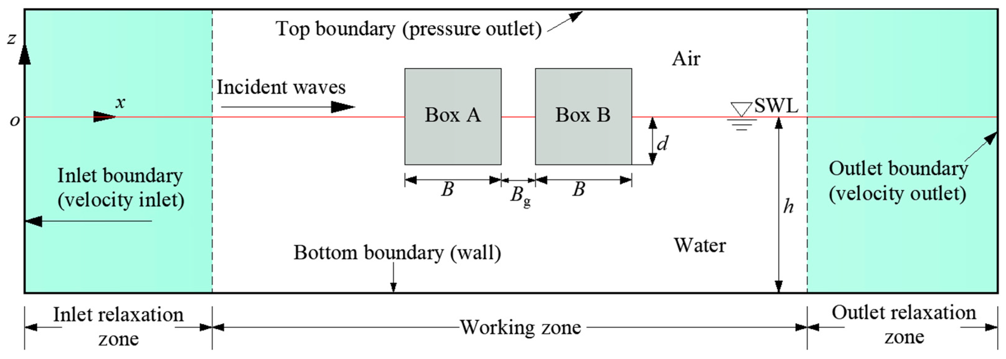
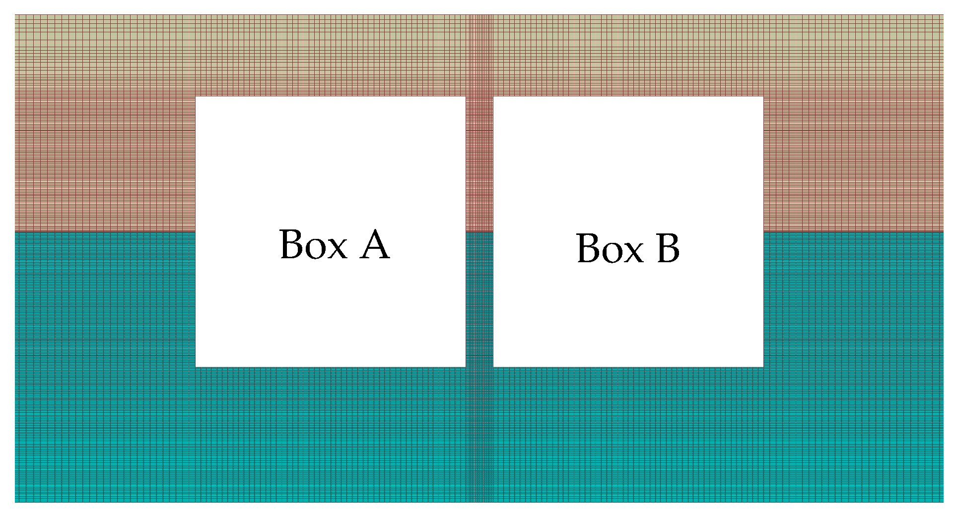
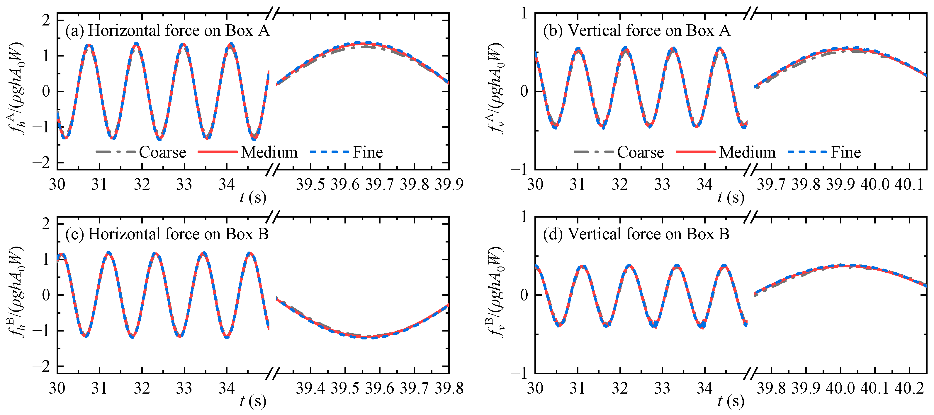
2. Description of Numerical Model

One of the practical methods to simulate the waves with more accuracy is using CFD solvers. Navier–Stokes equations could afford this by considering an appropriate related solver. An open-source solver, OpenFOAM, uses the Navier–Stokes equation and is implemented for numerically simulating the system. In the present study, a two-phase problem, air and water are solved by the volume of fluid (VOF) technique and related boundary and initial conditions. The wave generation and absorption schemes are simulated numerically with a third-party toolbox waves2Foam in OpenFOAM, and the solver waveDyMFoam is adopted to calculate the Navier–Stokes equations for water and air [43,44]. The governing equations can be formulated as:
ρ u i x i   =   0
ρ u i t   +   ρ ( u j u j m ) u i x j   =   ρ f i     p x i   +   μ x j ( u i x j   +   u j x i )
in which ρ is the fluid density, ui is the velocity of the fluid along the i-axis direction (i represents x, y, or z), u i m is the velocity component of the deformed meshes, p is the dynamic pressure, and μ is the fluid dynamic viscosity. f i is the external body force and only the gravity is taken into consideration in the present study.
The methodology of volume of fluid (VOF) is used to capture the free water surface, which can accurately predict the free surface flow in numerical simulations of hydraulic phenomena [45,46]. The fractional function of VOF, γ, for a computational cell is defined as:
γ   =   0 ,         in   air 0   <   γ   <   1 , on   the   surface 1 ,         in   water
It follows the following advection equation:
γ t   +   ( u i u i m ) γ x i   +   u r γ ( 1 γ )   =   0
in which u r   =   u w u a is the relative velocity between the water and the air. γ = 0.5 represents the free water surface in the present simulations. The effective fluid viscosity and the effective fluid density can then be respectively formulated as:
μ   =   ( 1 γ ) μ a   +   γ μ w ,
ρ   =   ( 1 γ ) ρ a   +   γ ρ w
in which the subscripts “a” and “w” represent the physical quantities of the air and the water, respectively.
In the waves2Foam toolbox, the way of generating and absorbing waves lies in arranging the so-called relaxation zones (refer to Figure 1). Hydrostatic pressure combined with zero velocity is set as the initial condition. The velocity at the inlet boundary is set to the analytical velocity of the desired incident wave trains, and the gradient of pressure is set to zero; while at the outlet boundary, both velocity and the pressure gradient are set to zero so as to dissipate the outgoing waves therein. The boundary conditions at the top boundary of the wave tank, the bottom boundary of the wave tank, and all the side walls of the fixed boxes are “atmosphere” and “no-slip”, respectively. The velocity boundary condition of the floating box is denoted as “movingWallVelocity”. The initial conditions of movement for Boxes A and B are “fixedValue” and “calculated”, respectively, where the “calculated” condition means that the movement is determined by the motion solver.
The governing equations are spatially discretized by the finite volume method. The pressure and velocity are decoupled by the PISO (pressure implicit with splitting of operator) algorithm [47]. The PISO algorithm can well simulate the problems proposed in this work [21,37]. The Euler scheme discretizes the time derivatives. The free heave motion of the floating body (i.e., Box B) is solved by using the sixDoFRigidBodyMotion utility embedded in OpenFOAM. The time step Δ t is automatically determined and dynamically adjusted according to the Courant–Friedrichs–Lewy condition, and the largest Courant number allowed is set to 0.25.

3. Numerical Wave Tank

The numerical wave tank used in the current study is shown in Figure 1. The origin of the coordinate system is located on the still water surface, the +z-axial direction points upwards, and the +x-axial direction is consistent with the propagation direction of the incident waves. Two identical boxes, named as Box A and Box B, are arranged at the center of the wave tank. Box A always remains fixed, and Box B is allowed to freely heave under the actions of the incident waves. There is a narrow gap with a width of Bg = 0.05 m between them. Each box has a height of H = 0.5 m, a breadth of B = 0.5 m, a draft of d = 0.25 m, and a density of 500 kg/m3. The length and the height of the wave tank are 18.5 m and 0.9 m, respectively. The width of the wave tank along the y-axis direction (i.e., the direction perpendicular to the x-z plane) is W = 0.02 m. The water depth h is set to 0.5 m.
By utilizing an identical two-box system to that shown in Figure 1 but with the upriver box heaving freely and the downriver one fixed, He et al. [42] studied the characteristics of the wave loads exerting on both boxes during the steady-state gap resonance. As stated in Section 1, to understand how the relative position of the heaving box with respect to the incident wave direction affects the wave loads more comprehensively, some results from the work of He et al. [42] are also presented in this article for comparison. To simplify descriptions in the following, the structure system with the upriver box fixed and the downriver one heaving freely is named “B-Heave structure system”, and the structure system with the heaving upriver box and the fixed downriver one is called the “A-Heave structure system”.
The regular waves are generated based on the 2nd-order Stokes wave theory. Five incident wave heights (i.e., H0 = 0.01–0.05 m in interval of 0.01 m) are considered in this work. The incident wave frequency ω varies from 4.947 rad/s to 6.323 rad/s. Equivalently, the dimensionless wavenumber kh ranges from 1.41 to 2.10 (k is the wavenumber that can be determined by the linear dispersion relationship). In all simulations, two relaxation zones with the width of six meters each are placed on the left and the right sides of the wave tank to absorb the reflection and transmission waves.
The meshes are generated using the built-in mesh generating tool “blockMesh”. Figure 2 presents typical mesh layout near the two boxes. To save the simulation time, the meshes with variable resolution are adopted in the numerical wave tank. Specifically speaking, along the x-axial direction, compared with the meshes in the wave propagating zones in front of and at the rear of the two-box system, the meshes around the two boxes, especially inside the gap, have much higher resolution. Along the z-axial direction, the meshes around the still water surface have smaller sizes, while the meshes in the vicinity of the top/bottom boundaries have larger sizes. The mesh convergence verification for simulation results is performed by adopting three mesh layouts with different resolutions (i.e., coarse, medium, and fine) whose specific parameters are tabulated in Table 1.
According to the numerical results, as shown in Section 4.1, for the B-Heave structure system, the dimensionless wavenumber at which the largest horizontal wave force exerting on Box B occurs is kh = 1.73 for the incident waves with H0 = 0.01 m. Figure 3 illustrates the time histories of the horizontal and the vertical wave forces on both boxes at kh = 1.73 for the incident waves with H0 = 0.01 m. The numerical results for the three mesh layouts present little differences, especially for the medium and the fine meshes. Hereinafter, the medium mesh layout is employed in all numerical computations, and the whole calculation time is set to 50.0 s for all cases. As shown in Figure 3, the time histories of the wave forces exerting on both boxes have reached their steady states after 30.0 s. The analysis results that will be presented in the following section are extracted from the steady-state process (i.e., the time histories of wave forces from 30.0 s to 50.0 s).
The accuracy of OpenFOAM in reproducing various wave–structure interaction problems, including the gap resonance phenomenon, has been widely examined in the literature. Gao et al. [48] verified its accuracy in predicting the wave loads acting on one box under wave actions. Furthermore, many scholars have proved its ability to accurately calculate the wave forces on two structures during gap resonance occurring inside a two-box structure system [49,50].

4. Results and Discussion

The influence of the free heave motion of the downriver box on the wave loads (including the horizontal and the vertical wave forces) exerting on the two boxes are systematically investigated in this section. In the following, the amplitudes of the steady-state time histories of the horizontal and the vertical wave forces acting on Box A are represented as FhA and FvA, respectively. Correspondingly, their amplitudes on Box B are denoted as FhB and FvB, respectively.

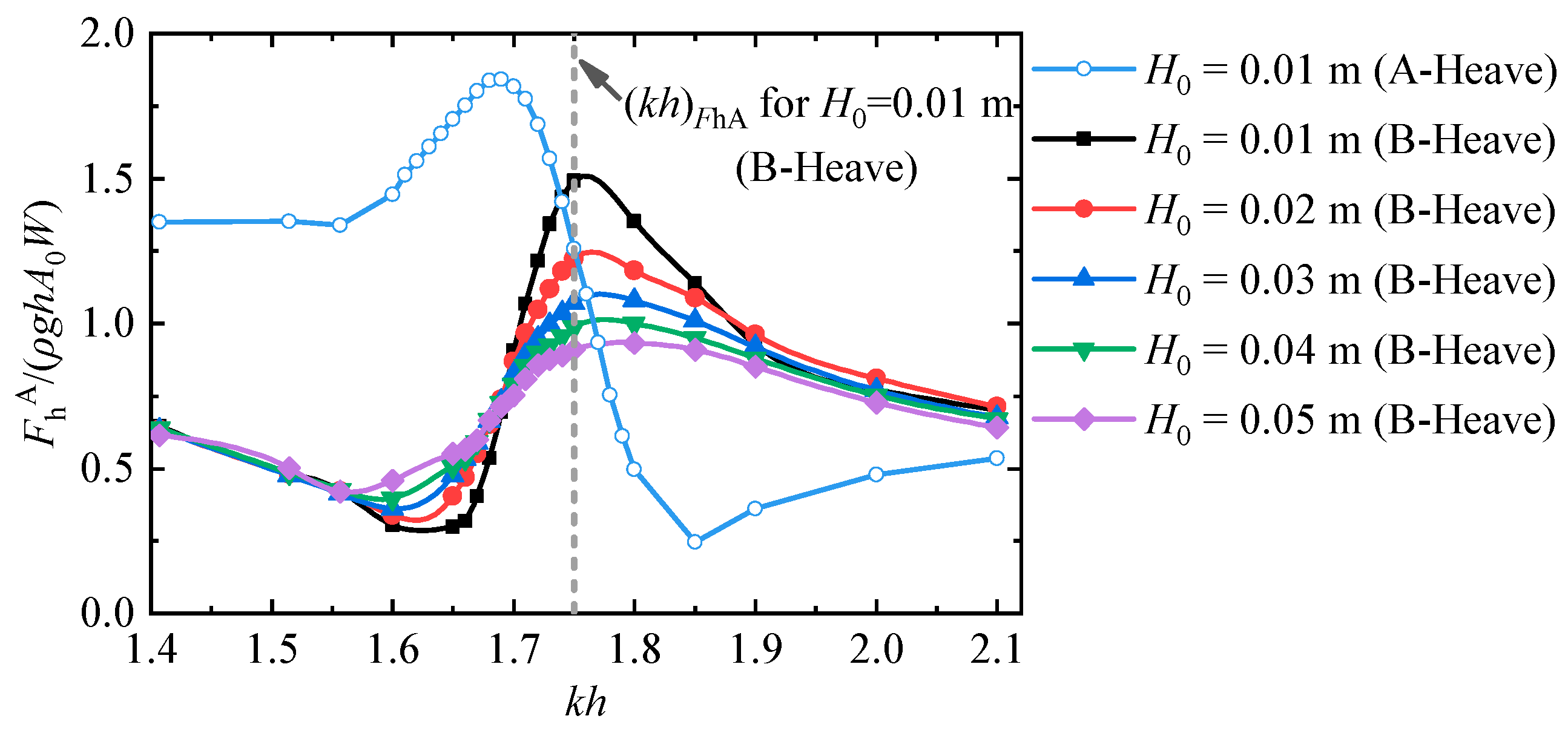
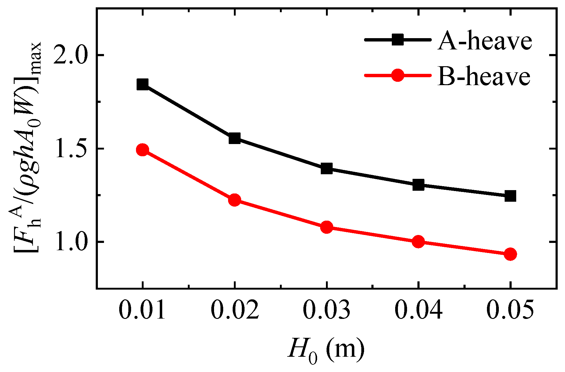
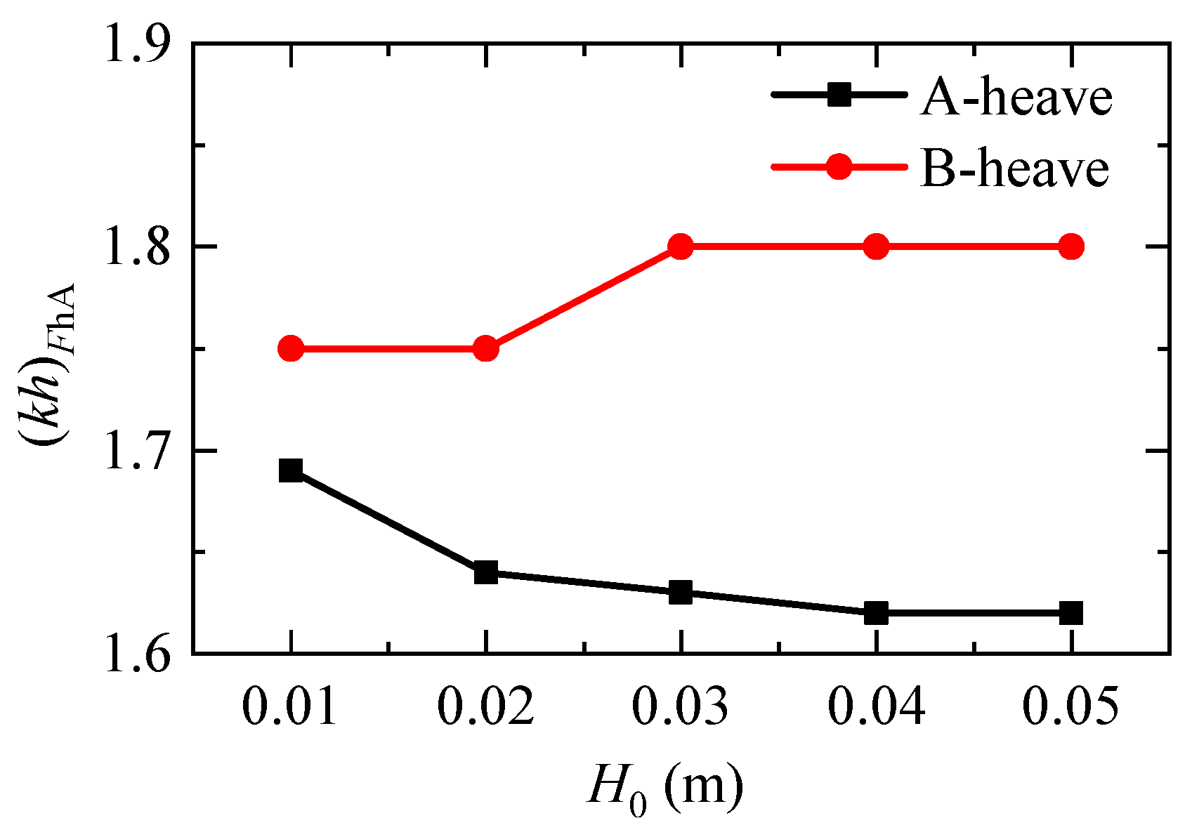
4.1. Horizontal Wave Forces on Box A

Figure 4 shows the variations of the normalized horizontal wave force on Box A for the B-Heave structure system. The numerical results for the A-Heave structure system with H0 = 0.01 m are also shown in this figure for comparison. Since the trends for the other incident wave heights are similar, only the result of H0 = 0.01 m is shown here. In this figure, the symbol “(kh)FhA” denotes the dimensionless wavenumber corresponding to the normalized largest horizontal wave forces on Box A. Three evident phenomena can be observed. Firstly, the changing trends of the horizontal wave force on Box A with respect to the dimensionless wavenumber for the A-Heave and the B-Heave structure systems are quite different. For the A-Heave structure system, the horizontal wave force on Box A first increases, then decreases, and finally increases with the rise of kh. For the B-Heave structure system, however, the tendency of the former seems to be “anti-phase” when compared to the A-Heave structure system. Specifically speaking, the horizontal wave force on Box A first decreases, then increases, and finally decreases again with the increase of kh.
Secondly, for the B-Heave structure system, the normalized largest horizontal wave force on Box A, [FhA/(ρghA0W)]max, gradually decreases as the incident wave height increases. This phenomenon is more clearly presented in Figure 5. In fact, for the A-Heave structure system, a similar tendency is also seen. This can be attributed to the fact that the energy dissipation due to fluid viscosity, flow rotation, and flow separation gradually increases with the increase of incident wave height. Besides, the normalized largest horizontal wave forces exerting on Box A, [FhA/(ρghA0W)]max, for the B-Heave structure system are always remarkably lower than those for the A-Heave structure system.
The third obvious phenomenon that can be seen from Figure 4 is that for the B-Heave structure system, its dimensionless wavenumber (kh)FhA clearly deviates from that for the A-Heave structure system. Furthermore, the value of (kh)FhA for the B-Heave structure system seems to increase gradually as the incident wave height increases. To better reveal the differences of (kh)FhA between the two structure systems, its variations with the incident wave height are further shown in Figure 6. It is found that the changing trend of (kh)FhA for the B-Heave structure system with H0 is distinct from that for the A-Heave structure system where (kh)FhA presents a monotonous downward tendency. Besides, the values of (kh)FhA for the B-Heave system are always larger than those for the A-Heave system within the whole range of the incident wave height considered in the current study.

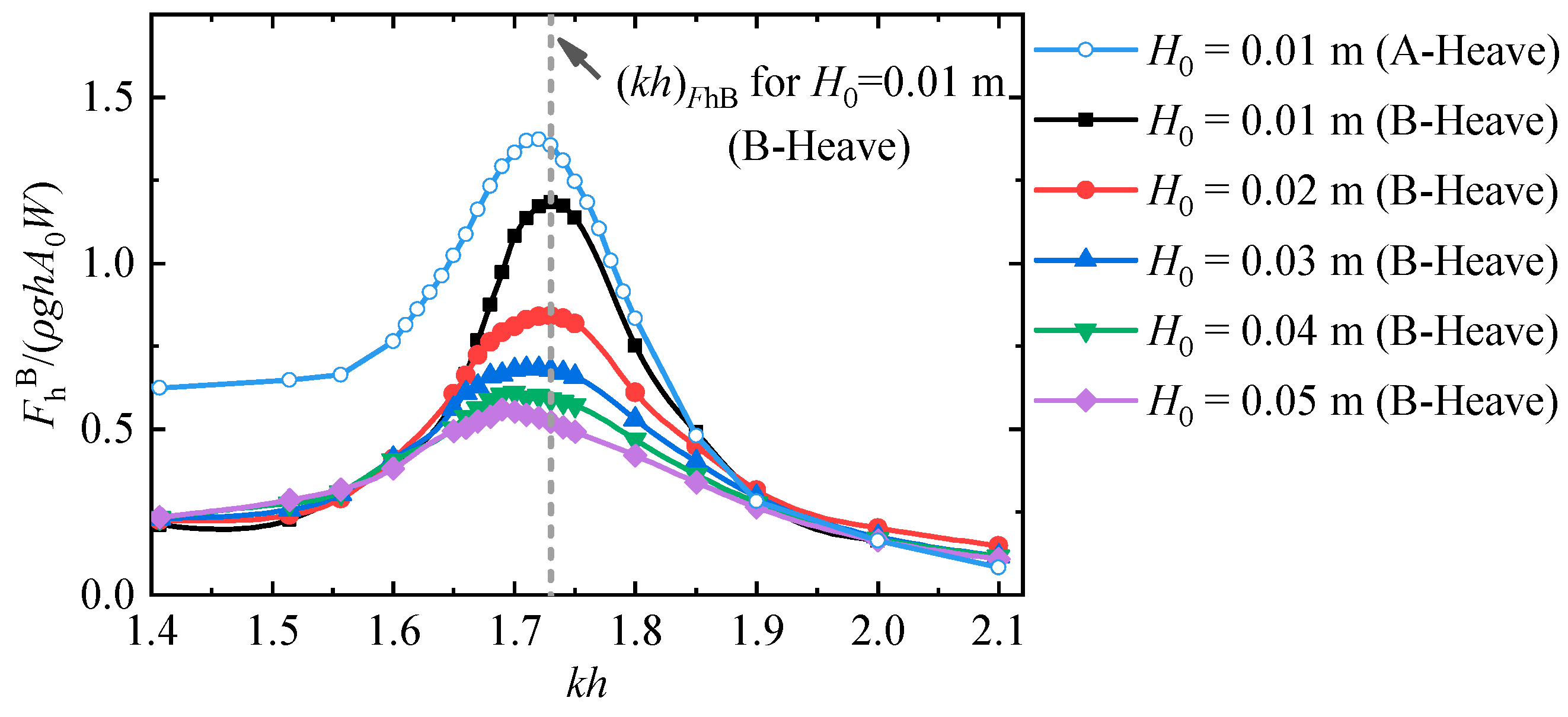
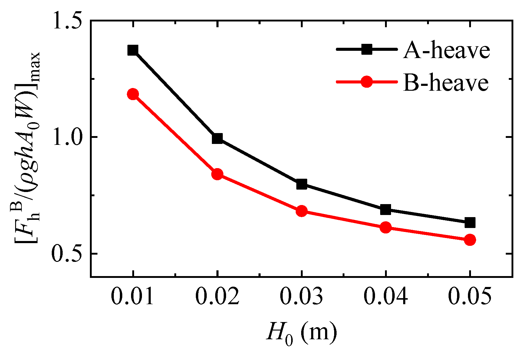
4.2. Horizontal Wave Forces on Box B

Figure 7 demonstrates the variations of the normalized horizontal wave force acting on Box B for both the A-Heave and the B-Heave structure systems, where (kh)FhB denotes the dimensionless wavenumber at which the normalized largest horizontal force exerting on Box B occurs. Unlike the horizontal force on Box A shown in Figure 4, the horizontal forces on Box B for both structure systems are shown to first increase and then decline with the dimensionless wavenumber. Furthermore, the normalized largest horizontal wave force acting on Box B for the B-Heave structure system shows a downward trend as the incident wave height increases.
The variations of the normalized largest horizontal wave force on Box B, [FhB/(ρghA0W)]max, against the incident wave height H0 for both the A-Heave and the B-Heave structure systems are further presented in Figure 8. It is seen that for both structure systems, the value of [FhB/(ρghA0W)]max shows a monotonic decreasing trend with the increase of H0. Besides, the value of [FhB/(ρghA0W)]max for the B-Heave structure system is always lower than the corresponding one for the A-Heave structure system, no matter whether the incident wave height is large or small. Both phenomena described above are consistent with those shown in Figure 5. Based on the phenomena in these two figures, it implies that the motion of the downriver box would cause smaller horizontal wave forces on both boxes when compared to the motion of the upriver box.
From Figure 7, it can also be intuitively observed that the dimensionless wavenumber (kh)FhB for the B-Heave structure system reduces gradually with the rise of incident wave height. Figure 9 further presents the variation trends of the frequency (kh)FhB against the incident wave height for both the A-Heave and the B-Heave structure systems. It is seen that for both structure systems, their values of (kh)FhB show a downward trend with the incident wave height. In addition, the values of (kh)FhB for the B-Heave structure system are always higher than those for the A-Heave structure system, which is similar to the corresponding phenomenon shown in Figure 6. This indicates that compared with the A-Heave structure system, the heave motion of the downriver box leads to the rise of the wave frequency at which the largest horizontal wave forces on both boxes occur.

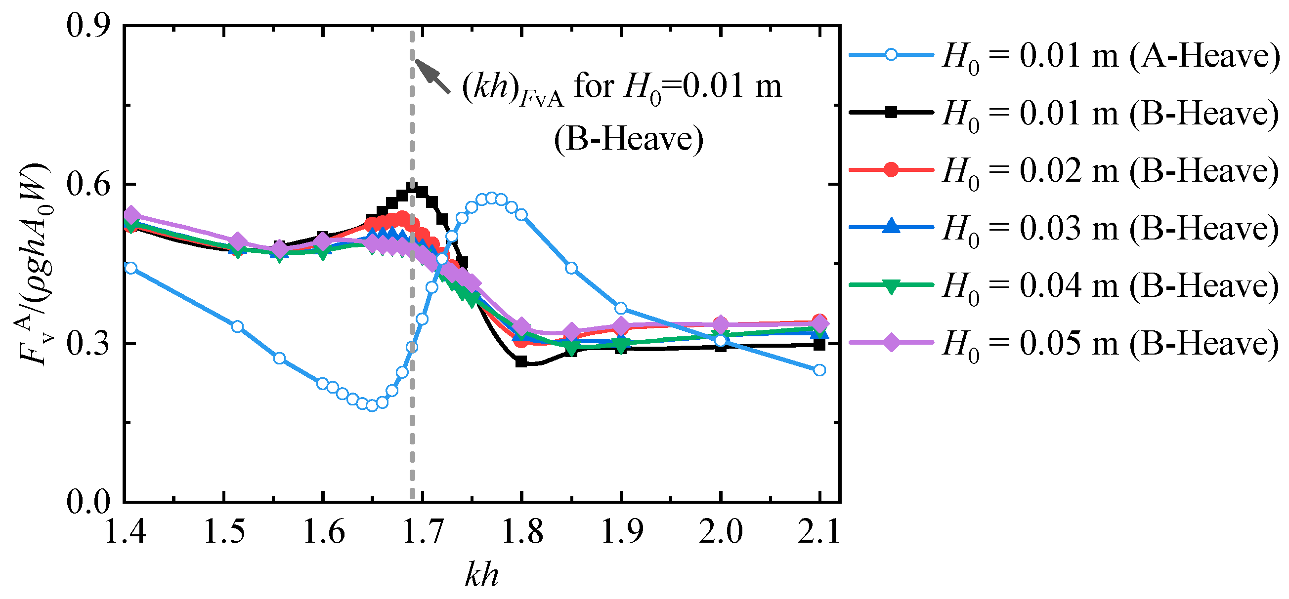
4.3. Vertical Wave Forces on Box A

Figure 10 demonstrates the variations of the normalized vertical wave force on Box A for the B-Heave structure system. The results for the A-Heave structure system with H0 = 0.01 m are also shown here for comparison. (kh)FvA in the figure represents the dimensionless wavenumber corresponding to the normalized largest vertical forces on Box A. The following three phenomena are easily seen. Firstly, approximately antiphase tendencies of the vertical wave force on Box A with respect to kh are observed for both structure systems. For the A-Heave structure system, the vertical wave force on Box A first decreases, then increases, and finally decreases again with kh. While for the B-Heave structure system, the vertical wave force on Box A first slightly decreases, then increases, then decreases, and finally increases slowly with the increase of kh.
Secondly, for the B-Heave structure system, the normalized maximum vertical wave force on Box A shows a downward trend with the incident wave height. Figure 11 further demonstrates the variations of the normalized largest vertical wave force on Box A, [FvA/(ρghA0W)]max, with respect to H0 for both the A-Heave and B-Heave structure systems. For both structure systems, the values of [FvA/(ρghA0W)]max, decrease monotonically with H0. Besides, [FvA/(ρghA0W)]max for the B-Heave structure system is shown to be always higher than the corresponding one for the A-Heave structure system.
The third evident phenomenon reflected from Figure 10 is that for the B-Heave structure system, its value of (kh)FvA is clearly different from the corresponding one for the A-Heave structure system. To show their differences more comprehensively, the values of (kh)FvA for all the incident wave heights and for both structure systems are further illustrated in Figure 12. It is seen that the values of (kh)FvA for the B-Heave system are always lower than those for the A-Heave system, regardless of H0. Furthermore, (kh)FvA for the B-Heave system is shown to decrease monotonically with H0, which is also quite different from the A-Heave system where the former increase gradually with the latter.

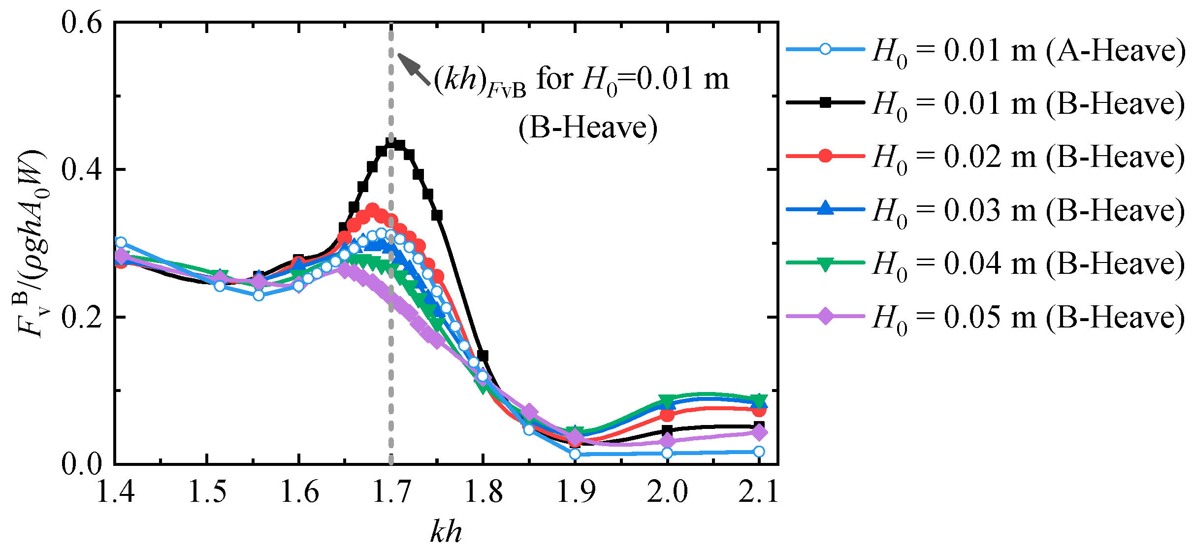
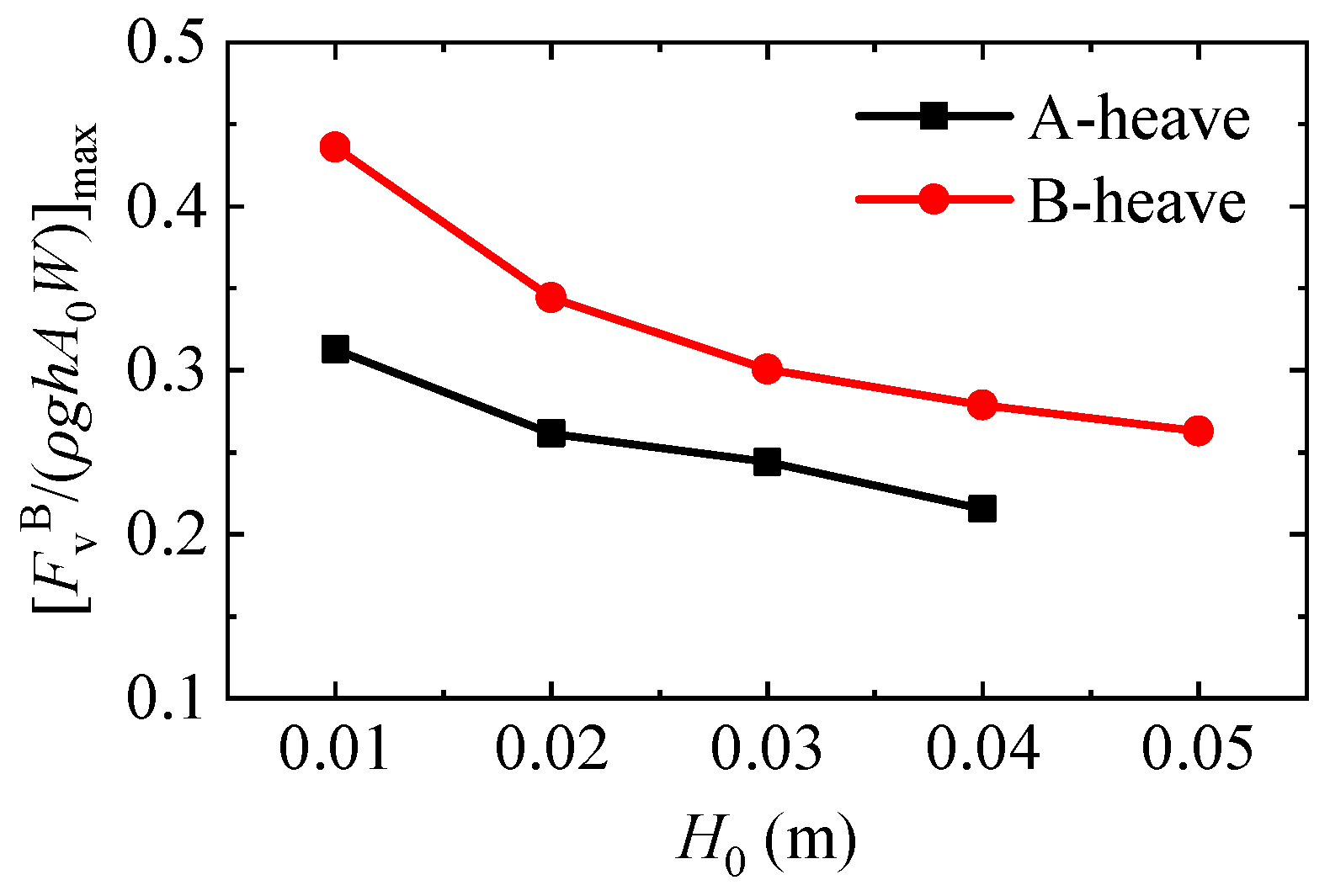
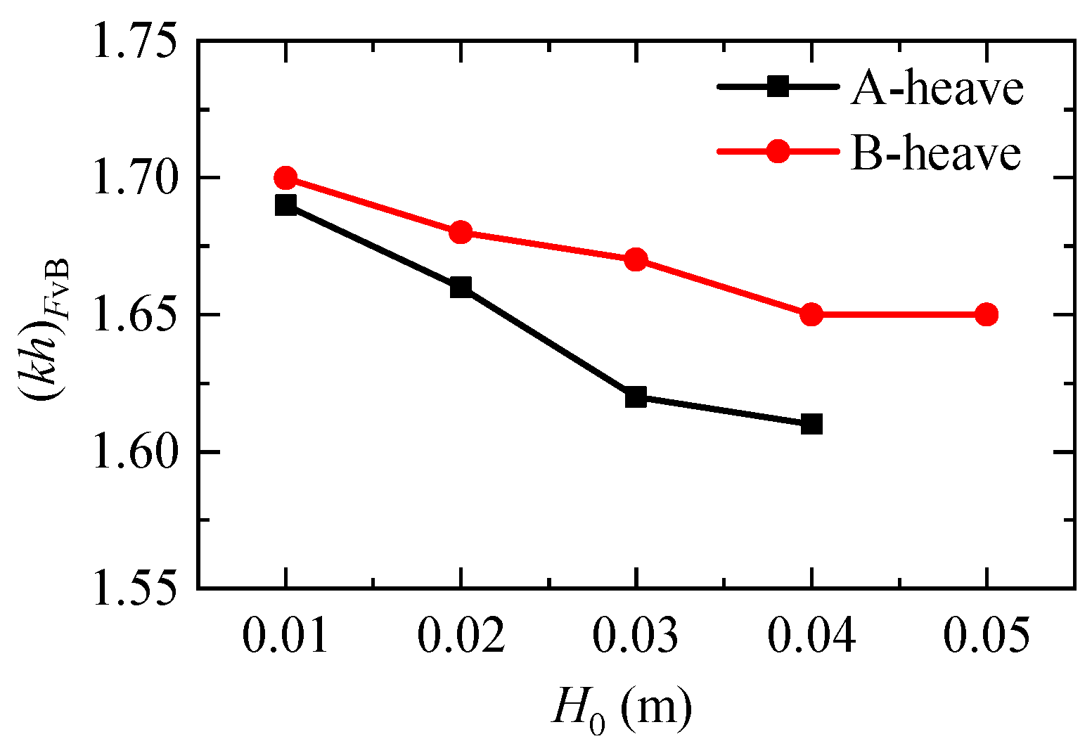
4.4. Vertical Wave Forces on Box B

Figure 13 presents the variations of the normalized vertical wave force on Box B for the B-Heave structure systems. The corresponding results for the A-Heave structure system with H0 = 0.01 m are presented as well for comparison. (kh)FvB in Figure 13 denotes the dimensionless wavenumber at which the normalized largest vertical force acting on Box B occurs. For both structure systems, the vertical wave forces on Box B are shown to first slightly decrease, then sharply increase, then sharply decrease, and finally to increase slowly with kh.
Figure 14 demonstrates the tendency of the normalized largest vertical wave force on Box B, [FvB/(ρghA0W)]max, with respect to the incident wave height, H0. The former is shown to decline monotonically with the latter for both structure systems. Besides, the values of [FvB/(ρghA0W)]max for the B-Heave system are consistently higher than those for the A-Heave system for all the five incident wave heights considered. These two phenomena mentioned above are consistent with those presented in Figure 11. These indicate that compared with the heave motion of the upriver box (i.e., Box A), the heave motion of the upriver box (i.e., Box B) leads to the increase of the vertical wave forces exerting on both boxes.
Figure 15 goes a step further to show the changing tendency of (kh)FvB against the incident wave height for both the two structure systems. It is seen that the value of (kh)FvB for the B-Heave structure system is shown to be always higher than that for the A-Heave structure system. In addition, the larger the incident wave height is, the more significant the difference of (kh)FvB for both structure system becomes. This may be attributed to the fact that the influence of heave motion and the nonlinear effect of the free surface in the gap becomes greater with the increase of the incident wave height.

5. Conclusions

The gap resonance phenomenon formed in between two side-by-side boxes under the actions of regular waves with various wave heights and frequencies is simulated by using the open-sources CFD package OpenFOAM. The upriver box (i.e., Box A) remains fixed and the downriver one (i.e., Box B) is allowed to heave freely. The effects of the vertical degree of freedom of the downriver box on the wave loads (including the horizontal and the vertical wave forces) exerting on both boxes are systematically investigated in this article. He et al. [42] studied the influence of the vertical degree of freedom of the upriver box on the wave loads acting on the two boxes. For a comparative study, part of their research results is shown in this article as well. For the convenience of description, the two-box system in which Box A remains fixed, Box B which heaves freely is called the “B-Heave structure system” while the one with Box A heaving freely and Box B fixed is called the “A-Heave structure system”. The differences of the wave load characteristics between the two structure systems are thoroughly revealed.
Based on the current research results, the following conclusions can be drawn:
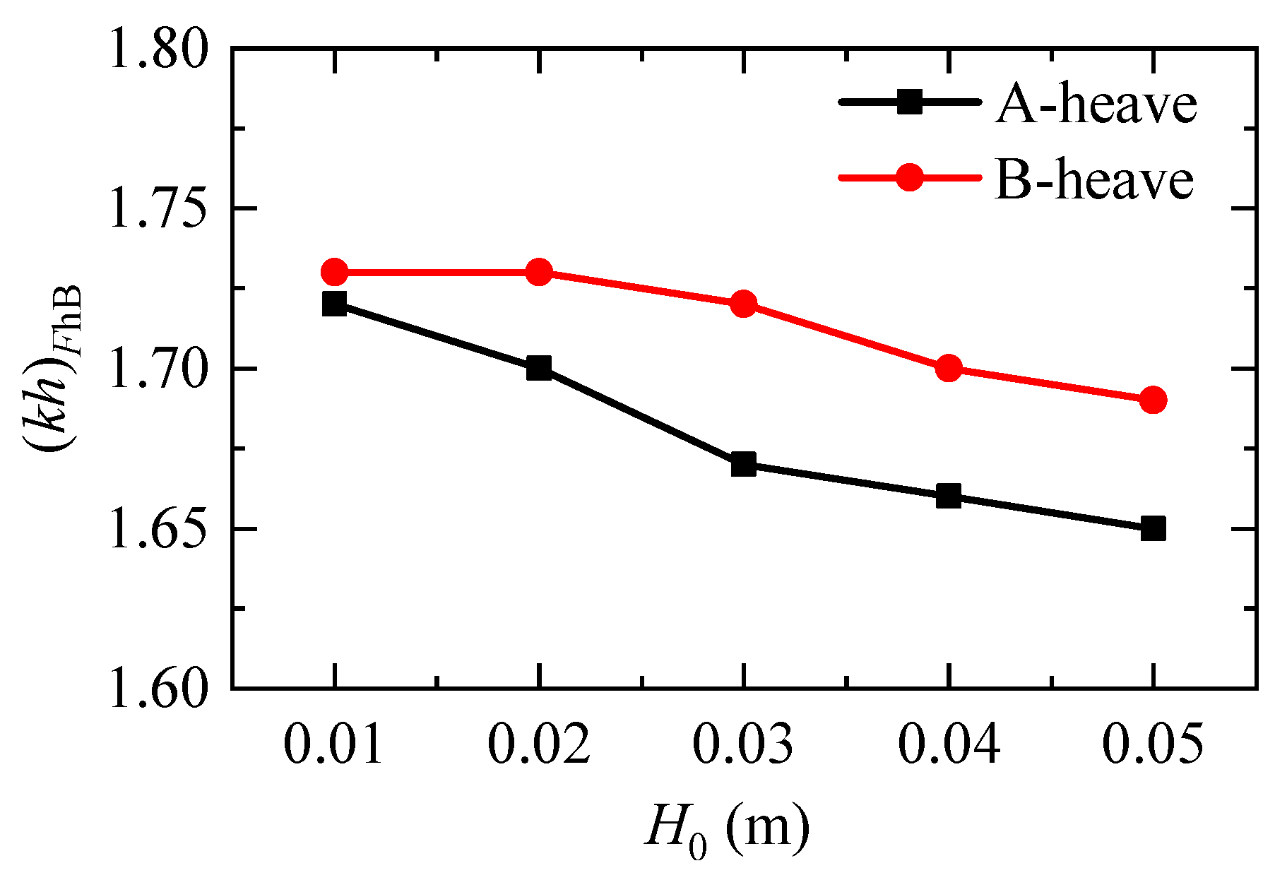
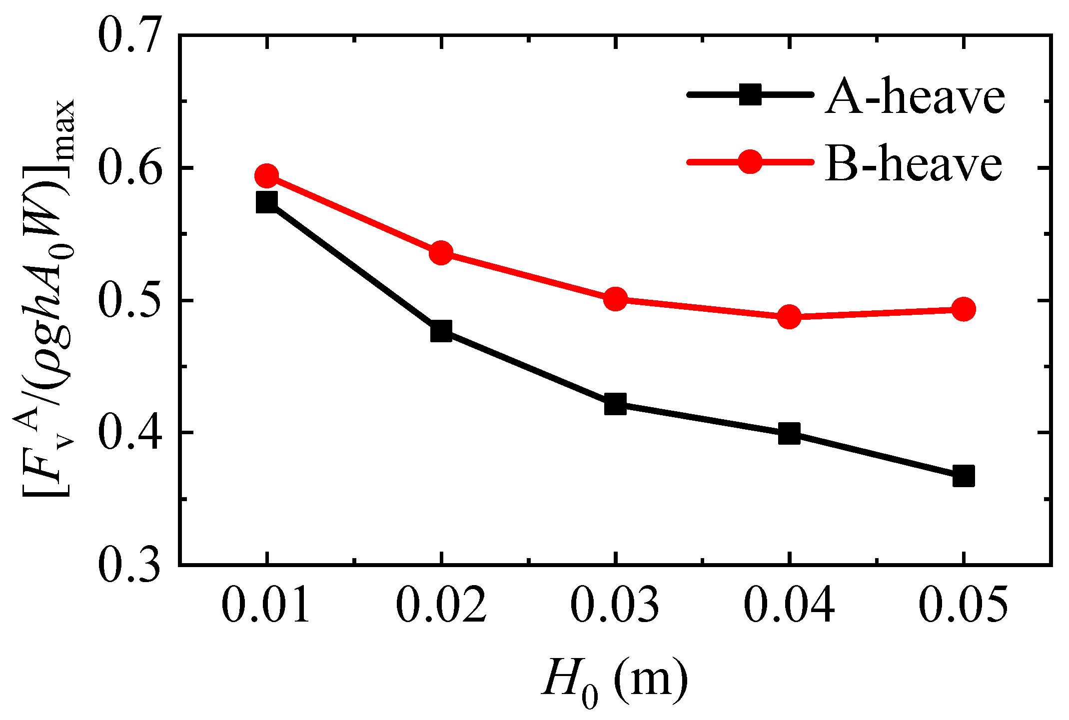
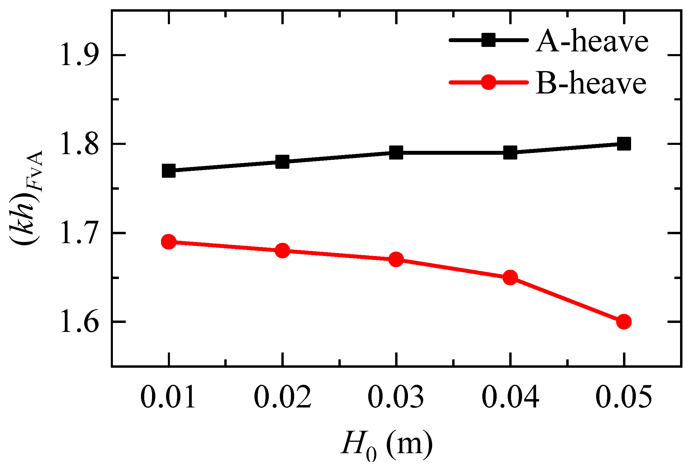
  • For the B-Heave structure system, both the normalized largest wave loads and the dimensionless wavenumber where the normalized largest wave loads occur are significantly influenced by the incident wave heights. The normalized largest wave loads acting on both boxes decrease gradually with the increase of the incident wave height, regardless of horizontal wave force or vertical wave force. For the horizontal wave force on Box B and the vertical wave forces on both boxes, the dimensionless wavenumber where the normalized largest wave loads occur decreases gradually with the incident wave height as well. However, for the horizontal wave force on Box A, the former shows an increasing trend as the incident wave height rises.
  • The relative position of the heaving box with respect to the incident wave direction has a significant effect on the characteristics of the wave loads exerting on both boxes. This is reflected in the following three aspects. (1) The changing trends of the wave loads on Box A (including the horizontal and the vertical wave forces) with respect to the wavenumber for the A-Heave and the B-Heave structure systems are almost anti-phase to each other. (2) Compared to the heave motion of the upriver box, the motion of the downriver box causes smaller maximum horizontal wave forces but larger maximum vertical wave forces exerting on both boxes. Furthermore, except for the vertical wave forces on Box A, the motion of the downriver box always results in a significant increase of the dimensionless wavenumber where the largest wave load appears. While for the vertical wave forces on Box A, the former leads to the opposite phenomenon.
Finally, we reaffirm here that these conclusions are only valid for the given geometric layout (including the size, density, and draft of the two boxes, the gap width, and the water depth), the vertical degree of freedom of the upriver or the downriver box, and the ranges of the incident wave height and the incident wave frequency studied in this paper.

Author Contributions

Conceptualization, J.G. and Z.H.; methodology, J.G. and H.S.; software, S.G.; validation, J.G., Z.H. and S.G.; formal analysis, J.G. and J.Z.; investigation, J.G.; resources, J.G. and T.Z.; data curation, S.G.; writing—original draft preparation, Z.H.; writing—review and editing, J.G., S.G. and X.B.; funding acquisition, J.G., J.Z. and H.S. All authors have read and agreed to the published version of the manuscript.

Funding

This research is financially supported by the National Natural Science Foundation of China (Grant No. 51911530205), the Science and Technology Development Fund of Macau SAR (Grant Nos. 0009/2021/A, SKL-IOTSC(UM)-2021-2023), the Key Laboratory of Port, Waterway and Sedimentation Engineering of MOT (Grant No. YK222001-2), Shandong Provincial Key Laboratory of Ocean Engineering (Grant No. kloe202010), the Key R&D Projects in Guangdong Province (No. 2020B1111500001), and the Qing Lan Project of Jiangsu Universities. The authors also thank the Royal Society (Grant No. IEC\NSFC\181321) for providing partial support for this work.

Institutional Review Board Statement

Not applicable.

Informed Consent Statement

Not applicable.

Data Availability Statement

Data available upon request.

Conflicts of Interest

The authors declare no conflict of interest.

References

  1. Liang, H.; Liu, X.; Chua, K.H.; de Mello, P.C.; Choo, Y.S. Wave actions on side-by-side barges with sloshing effects: Fixed-free arrangement. Flow 2022, 2, E20. [Google Scholar] [CrossRef]
  2. Jiang, S.-C.; Bai, W. Coupling analysis for sway motion box with internal liquid sloshing under wave actions. Phys. Fluids 2020, 32, 072106. [Google Scholar] [CrossRef]
  3. Gao, J.; Ma, X.; Dong, G.; Chen, H.; Liu, Q.; Zang, J. Investigation on the effects of Bragg reflection on harbor oscillations. Coast. Eng. 2021, 170, 103977. [Google Scholar] [CrossRef]
  4. Gao, J.; Ma, X.; Zang, J.; Dong, G.; Ma, X.; Zhu, Y.; Zhou, L. Numerical investigation of harbor oscillations induced by focused transient wave groups. Coast. Eng. 2020, 158, 103670. [Google Scholar] [CrossRef]
  5. Li, J.Y.; Liu, Z.; Liao, S.J.; Borthwick, A.G. Steady-state harmonic resonance of periodic interfacial waves with free-surface boundary conditions based on the homotopy analysis method. J. Fluid Mech. 2021, 916, A58. [Google Scholar] [CrossRef]
  6. Li, J.Y.; Liu, Z.; Liao, S.J.; Borthwick, A.G. Steady-state multiple near resonances of periodic interfacial waves with rigid boundary. Phys. Fluids 2020, 32, 087104. [Google Scholar] [CrossRef]
  7. Miao, G.; Saitoh, T.; Ishida, H. Water wave interaction of twin large scale caissons with a small gap between. Coast. Eng. J. 2001, 43, 39–58. [Google Scholar] [CrossRef]
  8. Molin, B. On the piston and sloshing modes in moonpools. J. Fluid Mech. 2001, 430, 27–50. [Google Scholar] [CrossRef]
  9. Saitoh, T.; Miao, G.; Ishida, H. Theoretical analysis on appearance condition of fluid resonance in a narrow gap between two modules of very large floating structure. In Proceedings of the 3rd Asia-Pacific Workshop on Marine Hydrodynamics, Shanghai, China, 27–28 June 2006; pp. 170–175. [Google Scholar]
  10. Ning, D.; Zhu, Y.; Zhang, C.; Zhao, M. Experimental and numerical study on wave response at the gap between two barges of different draughts. Appl. Ocean. Res. 2018, 77, 14–25. [Google Scholar] [CrossRef]
  11. Tan, L.; Lu, L.; Tang, G.Q.; Cheng, L.; Chen, X.B. A viscous damping model for piston mode resonance. J. Fluid Mech. 2019, 871, 510–533. [Google Scholar] [CrossRef]
  12. Kristiansen, T.; Faltinsen, O.M. Studies on resonant water motion between a ship and a fixed terminal in shallow water. J. Offshore Mech. Arct. Eng. 2009, 131, 021102. [Google Scholar] [CrossRef]
  13. Liu, Y.; Li, H.-j.; Lu, L.; Li, A.-j.; Tan, L. A semi-analytical potential solution for wave resonance in gap between floating box and vertical wall. China Ocean. Eng. 2020, 34, 747–759. [Google Scholar] [CrossRef]
  14. Faltinsen, O.M.; Rognebakke, O.F.; Timokha, A.N. Two-dimensional resonant piston-like sloshing in a moonpool. J. Fluid Mech. 2007, 575, 359–397. [Google Scholar] [CrossRef] [Green Version]
  15. Jiang, S.-C.; Liu, H.; Sun, T.-Z.; Gu, Q. Numerical simulation for hydrodynamic behavior of box-systems with and without narrow gaps. Ocean. Eng. 2020, 214, 107698. [Google Scholar] [CrossRef]
  16. Tan, L.; Tang, G.-q.; Zhou, Z.-b.; Cheng, L.; Chen, X.; Lu, L. Theoretical and numerical investigations of wave resonance between two floating bodies in close proximity. J. Hydrodyn. Ser. B 2017, 29, 805–816. [Google Scholar] [CrossRef]
  17. Ning, D.; Su, X.; Zhao, M.; Teng, B. Hydrodynamic difference of rectangular-box systems with and without narrow gaps. J. Eng. Mech. 2015, 141, 04015023. [Google Scholar] [CrossRef]
  18. Lu, L.; Cheng, L.; Teng, B.; Sun, L. Numerical simulation and comparison of potential flow and viscous fluid models in near trapping of narrow gaps. J. Hydrodyn. Ser. B 2010, 22, 120–125. [Google Scholar] [CrossRef]
  19. Chen, X.B. Hydrodynamics in Offshore and Naval Applications (Keynote lecture). In Proceedings of the 6th International Conference on Hydrodynamics, Perth, Austrilia, 24–26 November 2004. [Google Scholar]
  20. Liang, H.; Chua, K.-H.; Wang, H.-C.; Choo, Y.S. Numerical and experimental investigations into fluid resonance in a gap between two side-by-side vessels. Appl. Ocean. Res. 2021, 111, 102581. [Google Scholar] [CrossRef]
  21. Moradi, N.; Zhou, T.; Cheng, L. Effect of inlet configuration on wave resonance in the narrow gap of two fixed bodies in close proximity. Ocean. Eng. 2015, 103, 88–102. [Google Scholar] [CrossRef]
  22. He, G.; Chen, L.; Zhang, J.; Wang, X. Hydrodynamic resonance of three identical rectangular boxes with narrow gaps by a CIP method. Int. J. Offshore Polar Eng. 2019, 29, 437–445. [Google Scholar] [CrossRef]
  23. Gao, J.; Chen, H.; Zang, J.; Chen, L.; Wang, G.; Zhu, Y. Numerical investigations of gap resonance excited by focused transient wave groups. Ocean. Eng. 2020, 212, 107628. [Google Scholar] [CrossRef]
  24. Feng, X.; Bai, W. Wave resonances in a narrow gap between two barges using fully nonlinear numerical simulation. Appl. Ocean. Res. 2015, 50, 119–129. [Google Scholar] [CrossRef]
  25. Zhao, W.; Pan, Z.; Lin, F.; Li, B.; Taylor, P.H.; Efthymiou, M. Estimation of gap resonance relevant to side-by-side offloading. Ocean. Eng. 2018, 153, 1–9. [Google Scholar] [CrossRef]
  26. Zhao, W.; Taylor, P.H.; Wolgamot, H.A.; Eatock Taylor, R. Gap resonance from linear to quartic wave excitation and the structure of nonlinear transfer functions. J. Fluid Mech. 2021, 926, A3. [Google Scholar] [CrossRef]
  27. Gao, J.; He, Z.; Zang, J.; Chen, Q.; Ding, H.; Wang, G. Topographic effects on wave resonance in the narrow gap between fixed box and vertical wall. Ocean. Eng. 2019, 180, 97–107. [Google Scholar] [CrossRef]
  28. Gao, J.; He, Z.; Zang, J.; Chen, Q.; Ding, H.; Wang, G. Numerical investigations of wave loads on fixed box in front of vertical wall with a narrow gap under wave actions. Ocean. Eng. 2020, 206, 107323. [Google Scholar] [CrossRef]
  29. Liu, J.; Gao, J.; Shi, H.; Zang, J.; Liu, Q. Investigations on the second-order transient gap resonance induced by focused wave groups. Ocean. Eng. 2022, 263, 112430. [Google Scholar] [CrossRef]
  30. He, Z.; Gao, J.; Chen, H.; Zang, J.; Liu, Q.; Wang, G. Harmonic analyses of hydrodynamic characteristics for gap resonance between fixed box and vertical wall. China Ocean. Eng. 2021, 35, 712–723. [Google Scholar] [CrossRef]
  31. Yin, Y.; Jiang, S.-C.; Geng, B.-L. Fluid resonance in the narrow gap for a box close to a bottom-mounted wall with permeable bed. Ocean. Eng. 2022, 258, 111726. [Google Scholar] [CrossRef]
  32. Ding, Y.; Walther, J.H.; Shao, Y. Higher-order gap resonance between two identical fixed barges: A study on the effect of water depth. Phys. Fluids 2022, 34, 052113. [Google Scholar] [CrossRef]
  33. Zou, M.; Chen, M.; Zhu, L.; Li, L.; Zhao, W. A constant parameter time domain model for dynamic modelling of multi-body system with strong hydrodynamic interactions. Ocean. Eng. 2023, 268, 113376. [Google Scholar] [CrossRef]
  34. Li, Y. Fully nonlinear analysis of second-order gap resonance between two floating barges. Eng. Anal. Bound. Elem. 2019, 106, 1–19. [Google Scholar] [CrossRef]
  35. Li, Y.; Zhang, C. Analysis of wave resonance in gap between two heaving barges. Ocean. Eng. 2016, 117, 210–220. [Google Scholar] [CrossRef]
  36. He, G.; Jing, P.; Jin, R.; Zhang, W.; Zhang, J.; Liu, T. Two-dimensional numerical study on fluid resonance in the narrow gap between two rigid-connected heave boxes in waves. Appl. Ocean. Res. 2021, 110, 102628. [Google Scholar] [CrossRef]
  37. Gao, J.; He, Z.; Huang, X.; Liu, Q.; Zang, J.; Wang, G. Effects of free heave motion on wave resonance inside a narrow gap between two boxes under wave actions. Ocean. Eng. 2021, 224, 108753. [Google Scholar] [CrossRef]
  38. He, Z.; Gao, J.; Shi, H.; Zang, J.; Chen, H.; Liu, Q. Investigation on effects of vertical degree of freedom on gap resonance between two side-by-side boxes under wave actions. China Ocean. Eng. 2022, 36, 403–412. [Google Scholar] [CrossRef]
  39. Gao, J.-L.; Lyu, J.; Wang, J.-H.; Zhang, J.; Liu, Q.; Zang, J.; Zou, T. Study on Transient Gap Resonance with Consideration of the Motion of Floating Body. China Ocean. Eng. 2022, 36, 994–1006. [Google Scholar] [CrossRef]
  40. Li, S.; Teng, B. Numerical examination of wave-induced coupling roll motion and fluid resonance between twin floating barges in proximity. Procedia Eng. 2015, 126, 242–246. [Google Scholar] [CrossRef] [Green Version]
  41. Lu, L.; Tan, L.; Zhou, Z.; Zhao, M.; Ikoma, T. Two-dimensional numerical study of gap resonance coupling with motions of floating body moored close to a bottom-mounted wall. Phys. Fluids 2020, 32, 092101. [Google Scholar] [CrossRef]
  42. He, Z.; Gao, J.; Zang, J.; Chen, H.; Liu, Q.; Wang, G. Effects of free heave motion on wave forces on two side-by-side boxes in close proximity under wave actions. China Ocean. Eng. 2021, 35, 490–503. [Google Scholar] [CrossRef]
  43. Bruinsma, N.; Paulsen, B.T.; Jacobsen, N.G. Validation and application of a fully nonlinear numerical wave tank for simulating floating offshore wind turbines. Ocean. Eng. 2018, 147, 647–658. [Google Scholar] [CrossRef]
  44. Jacobsen, N.G.; Fuhrman, D.R.; Fredsøe, J. A wave generation toolbox for the open-source CFD library: OpenFoam®. Int. J. Numer. Methods Fluids 2012, 70, 1073–1088. [Google Scholar] [CrossRef]
  45. Lauria, A.; Alfonsi, G.; Tafarojnoruz, A. Flow Pressure Behavior Downstream of Ski Jumps. Fluids 2020, 5, 168. [Google Scholar] [CrossRef]
  46. Tafarojnoruz, A.; Lauria, A. Large eddy simulation of the turbulent flow field around a submerged pile within a scour hole under current condition. Coast. Eng. J. 2020, 62, 489–503. [Google Scholar] [CrossRef]
  47. Jasak, H. Error Analysis and Estimation in the Finite Volume Method with Applications to Fluid Flows. Ph.D. Thesis, Imperial College, London, UK, 1996. [Google Scholar]
  48. Gao, J.; Zang, J.; Chen, L.; Chen, Q.; Ding, H.; Liu, Y. On hydrodynamic characteristics of gap resonance between two fixed bodies in close proximity. Ocean. Eng. 2019, 173, 28–44. [Google Scholar] [CrossRef]
  49. Jiang, S.-C.; Bai, W.; Yan, B. Higher-order harmonic induced wave resonance for two side-by-side boxes in close proximity. Phys. Fluids 2021, 33, 102113. [Google Scholar] [CrossRef]
  50. Moradi, N.; Zhou, T.; Cheng, L. Two-dimensional numerical study on the effect of water depth on resonance behaviour of the fluid trapped between two side-by-side bodies. Appl. Ocean. Res. 2016, 58, 218–231. [Google Scholar] [CrossRef] [Green Version]
Figure 1. Sketch of the numerical wave tank.
Jmse 11 00448 g001
Figure 2. Typical layout of the computational meshes near the two boxes.
Jmse 11 00448 g002
Figure 3. Mesh dependence tests for the wave forces on both boxes, in which A0= H0/2 denotes the amplitude of the incident waves.
Jmse 11 00448 g003
Figure 4. Variations of the normalized horizontal wave force on Box A for the B-Heave structure systems. The results for the A-Heave structure system with H0 = 0.01 m is also shown here for comparison.
Jmse 11 00448 g004
Figure 5. Variations of the normalized largest horizontal wave forces on Box A, [FhA/(ρghA0W)]max, with respect to the incident wave height.
Jmse 11 00448 g005
Figure 6. Variations of the dimensionless wavenumber (kh)FhA with respect to the incident wave height for both the A-Heave and B-Heave structure systems.
Jmse 11 00448 g006
Figure 7. As in Figure 4, but for the normalized horizontal wave force on Box B.
Jmse 11 00448 g007
Figure 8. Variations of the normalized largest horizontal wave forces on Box B, [FhB/(ρghA0W)]max, against the incident wave height for both structure systems.
Jmse 11 00448 g008
Figure 9. Variations of (kh)FhB against the incident wave height for both the A-Heave and the B-Heave structure systems.
Jmse 11 00448 g009
Figure 10. Variations of the normalized vertical wave force on Box A for the B-Heave structure system. The results for the A-heave structure system with H0 = 0.01 m is also shown for comparison.
Jmse 11 00448 g010
Figure 11. Variations of the normalized largest vertical wave force on Box A, [FvA/(ρghA0W)]max, against the incident wave height.
Jmse 11 00448 g011
Figure 12. Variations of (kh)FvA with respect to the incident wave height for both structure systems.
Jmse 11 00448 g012
Figure 13. As in Figure 10, but for the normalized vertical wave force on Box B.
Jmse 11 00448 g013
Figure 14. Variations of the normalized largest vertical wave forces on Box B, [FvB/(ρghA0W)]max, with the incident wave height.
Jmse 11 00448 g014
Figure 15. Variations of the frequency (kh)FvB with the incident wave height.
Jmse 11 00448 g015
Table 1. Details of the Coarse, Medium and Fine meshes.
Mesh No. of CellsNo. of PointsNo. of FacesSize of Cells across the Gap (m)
ΔxΔz
Coarse79,850161,548320,3250.00500.0040
Medium 211,960426,970849,3660.00310.0020
Fine 317,400638,3381,271,3700.00250.0016
Disclaimer/Publisher’s Note: The statements, opinions and data contained in all publications are solely those of the individual author(s) and contributor(s) and not of MDPI and/or the editor(s). MDPI and/or the editor(s) disclaim responsibility for any injury to people or property resulting from any ideas, methods, instructions or products referred to in the content.

