Article

Generalized Behavior Decision-Making Model for Ship Collision Avoidance via Reinforcement Learning Method

Navigation College, Dalian Maritime University, Dalian 116026, China
*
Author to whom correspondence should be addressed.
J. Mar. Sci. Eng. 2023, 11(2), 273; https://doi.org/10.3390/jmse11020273
Submission received: 21 December 2022 / Revised: 16 January 2023 / Accepted: 20 January 2023 / Published: 25 January 2023
(This article belongs to the Special Issue AI for Navigation and Path Planning of Marine Vehicles)

Abstract

:
Due to the increasing number of transportation vessels, marine traffic has become more congested. According to the statistics, 89% to 95% of maritime accidents are related to human factors. In order to reduce marine incidents, ship automatic collision avoidance has become one of the most important research issues in the field of ocean engineering. A generalized behavior decision-making (GBDM) model, trained via a reinforcement learning (RL) algorithm, is proposed in this paper, and it can be used for ship autonomous driving in multi-ship encounter situations. Firstly, the obstacle zone by target (OZT) is used to calculate the area of future collisions based on the dynamic information of ships. Meanwhile, a virtual sensor called a grid sensor is taken as the input of the observation state. Then, International Regulations for Preventing Collision at Sea (COLREGs) is introduced into the reward function to make the decision-making fully comply with COLREGs. Different from the previous RL-based collision avoidance model, the interaction between the ship and the environment only works in the collision avoidance decision-making stage. Finally, 60 complex multi-ship encounter scenarios clustered by the COLREGs are taken as the ship’s GBDM model training environments. The simulation results show that the proposed GBDM model and training method has flexible scalability in solving the multi-ship collision avoidance problem complying with COLREGs in different scenarios.

1. Introduction

Marine surface vessels autonomously sailing at sea has been the dream of ship designers for several decades. With the development of artificial intelligent decision-making technology, advanced sensors, and control methodology, this dream might come true soon [1]. Therefore, the concept of the marine autonomous surface vessel (MASS) was introduced by the International Maritime Organization (IMO) for fueling present ship intelligent collision avoidance decision-making research [2]. The issue of autonomous collision avoidance on ships is one of the decision-making optimization problems that scholars have paid long attention to.
Numerous model-based collision avoidance methods have been proposed in the field of MASS, such as the artificial potential field (APF) method, the velocity obstacle (VO) method, the A* method, particle swarm optimization (PSO) path planning, and the inference of the time of collision avoidance algorithm [3,4,5,6,7,8]. However, the model-based method does not have self-learning ability, and the model complexity is too high [9]. Although the model-based ship collision avoidance method has a good effect on the known model problems, it is difficult to establish a complete anti-collision model for numerous problems due to the complexity of real sea conditions. Most model-based algorithms have difficulty predicting the uncertainty in practical applications.
In recent years, with the rapid development of machine learning, especially reinforcement learning, artificial intelligence technology has been applied to ship collision avoidance decision-making. Model-free RL methods have strong self-learning ability, which is the most suitable method to solve those problems. The RL has the advantage that it does not depend on model construction. Relying on the state transition information collected through interaction with the environment, bypassing the complex problems such as system modeling, the RL agent can implement sequential decision-making through the Q-tables updates. Although fruitful research results based on the RL have been presented, there are still some problems to be solved in RL-based research. In previous studies, the model via RL algorithm, which is applied to the collision avoidance process, might increase the state transition chain length and lead to an explosion in computation complexity. Furthermore, the RL algorithm relies heavily on the input of the observation state, which directly affects the learning speed of the agent. In previous studies, the ship kinematic, dynamic, and environmental information, such as own ship’s and target ships’ course, speed, distance to the target, bearing, and so on, have usually been used as the input of the behavior decision-making Q-table model. That leads to a multi-dimensional Q-table structure to solve this problem. All the more so, the quantity of target ships might result in “dimensionality curse“ of observed states. In addition, in previous studies, most RL-based collision avoidance models make decisions that conform to COLREGs by designing complex reward functions. Due to the overly complex model, this method will lead to model learning difficulties. Motivated by the above analysis of the previous research problems, the contributions of this paper can be concluded as follows:
(1)
The GBDM model trained via RL algorithm is only used in the collision avoidance behavior decision-making stage, which reduces the model computation burden and improves the efficiency of the model executive performance.
(2)
Based on the virtual sensor called the grid sensor, the grid sensor is quantified as the input to the RL agent, which determines the dimensionality of the observation state of the GBDM model and clusters similar ship collision avoidance scenarios.
(3)
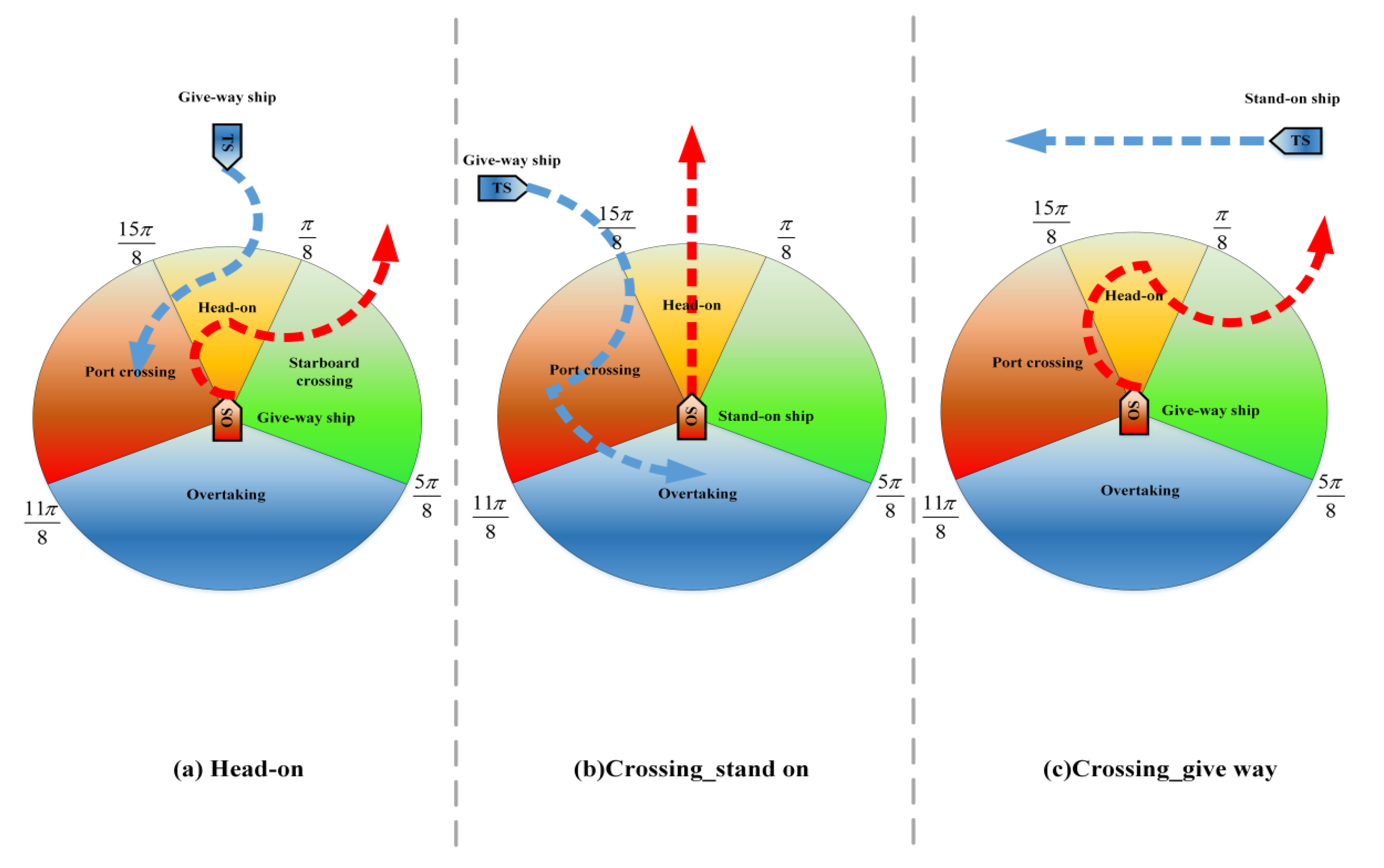
When designing the reward function of RL, COLREGs are taken into account so that the ship’s collision avoidance operation is mainly starboard side alteration.
(4)
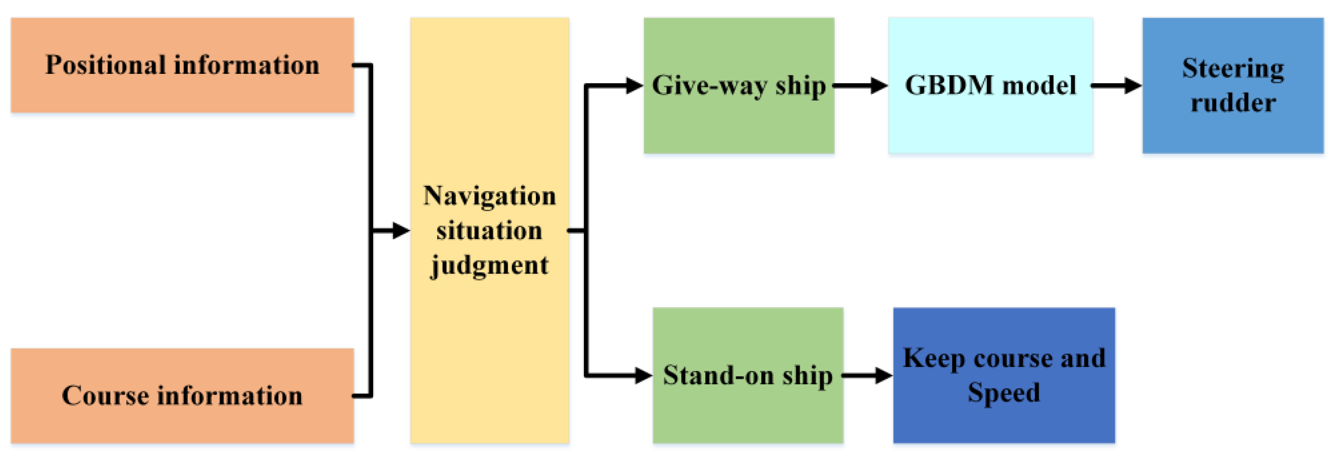
With the introduction of the navigational situation judgement, the ship can be recognized to be the give-way vessel or the stand-on vessel before the GBDM model makes an avoidance decision, which makes the decision-making more compliant with COLREGs without the increase in model complexity.

2. Literature Review and Motivation

So far, the issue of automatic collision avoidance in ships has attracted the attention of numerous researchers, and related theories and techniques have been continuously updated and developed. Generally, two major methods are divided: the model-based method and the model-free method. Before the rapid development of machine learning, model-based collision avoidance algorithms such as the APF method, the VO method, the A* method, PSO path planning, and inference of the time of collision avoidance algorithm were proposed. Based on the general requirements of COLREGs and APF method, Lee et al. proposed a multi-ship collision avoidance and route generation algorithm [3]. The simulation results showed that the proposed anti-collision formulation can safely avoid collisions within a pre-determined distance. Lyu et al. proposed an improved APF, which contained a new improved repulsive potential field function and the corresponding virtual force to solve the collision avoidance problem between dynamic obstacles and static obstacles. Simulation results highlighted that the proposed method could quickly determine path planning in complex situations and take into account the unpredictable strategies of different ships [4]. Wang et al. proposed a ship collision avoidance decision-making system based on the improved VO method. The improved VO method had good robustness and effectiveness in various ocean scenarios [5]. Liu et al. proposed an improved A* algorithm that considers COLREGs and ship maneuverability, and the automatically generated path was economical and safe [6]. E Krell et al. proposed an improved PSO to solve the problem of the PSO algorithm falling into local optimum [7]. In order to evaluate the risk of collision avoidance, Wang et al. proposed a risk assessment system based on TCPA and DCPA to estimate the risk of ship collision [8].
Although some studies have demonstrated the ability of the model-based method to ship collision-free paths, several challenges must be addressed. As the marine traffic become more complex, model-based methods cannot be effectively extended to deal with a large number of target ships in dense traffic. In addition, the model-based methods make the model overly complex for considering all possible situations. Hence, minor changes in the environment may cause failure. Since model-based methods do not have self-learning ability, most algorithms cannot predict uncertainty in practical applications. The model-free RL algorithm can excellently adapt to complex systems and has good self-learning ability, which provides an effective way to solve extremely complex systems and find the optimal policies from unknown environments through trial and error interaction [10,11,12].
In recent years, many scholars have focused on multi-ship obstacle avoidance decision problems based on RL algorithm. Shen et al. proposed an automatic collision avoidance algorithm based on deep Q-learning (DQN). Through experiments, it is proved that the DQN-trained model has the possibility of achieving ships automatic collision avoidance [13]. Based on the Deep Neural Network (DNN), Zhao et al. proposed a multi-ship collision avoidance method that could directly map the states of encountered ships to the steering rudder angle via the decision model. Moreover, the ship encounter situations are classified into four regions based on COLREGs, and only the nearest ships in each region are considered as the target ships. The simulation results indicated that the trained DNN model can avoid collision in the most encounter situations [14]. Guo et al. designed a DQN algorithm using environmental state information as the training space, which could be quantified according to the actual navigation environment and COLREGs. Shipping navigation safety could be guaranteed by setting a series of collision avoidance reward functions [
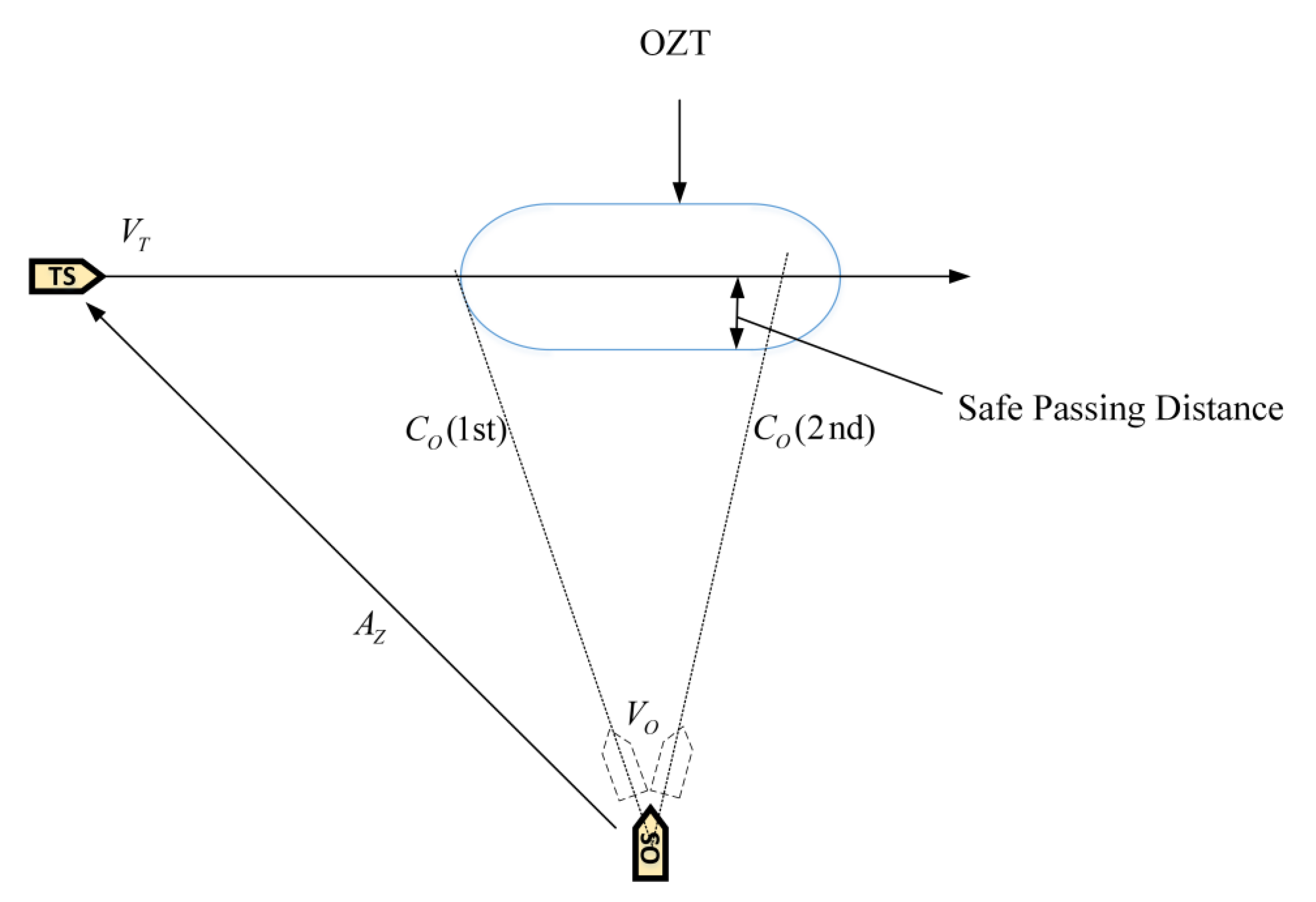
15]. Sawada et al. presented an automatic collision avoidance algorithm based on proximal policy optimization (PPO). Then, they proposed a novel virtual sensor based on the obstacle zone by target (OZT). Simulation results indicated that the model could handle up to three target ships [16]. Woo et al. presented a new grid map representation based on the visual recognition ability of convolutional neural network (CNN). The DRL was applied to the model training for the USV collision avoidance problem. The experiments and simulations indicated the collision avoidance ability of the trained model [17]. Chun et al. proposed a collision risk assessment method based on the ship domain and the closest point of approach (CPA). The results indicated that the improved algorithm could effectively avoid collision and enhance navigation safety [18]. Li et al. utilized the APF algorithm to improve the action space and reward function of the DRL algorithm and set the collision avoidance zone based on the COLREGs. The simulation results showed that the improved DRL could achieve automatic collision avoidance and conform to COLREGs [19].
In summary, although fruitful research results based on the RL have been presented, the problems of complicated models and excessive input of observation states are also prominent. Related issues are shown in Table 1.
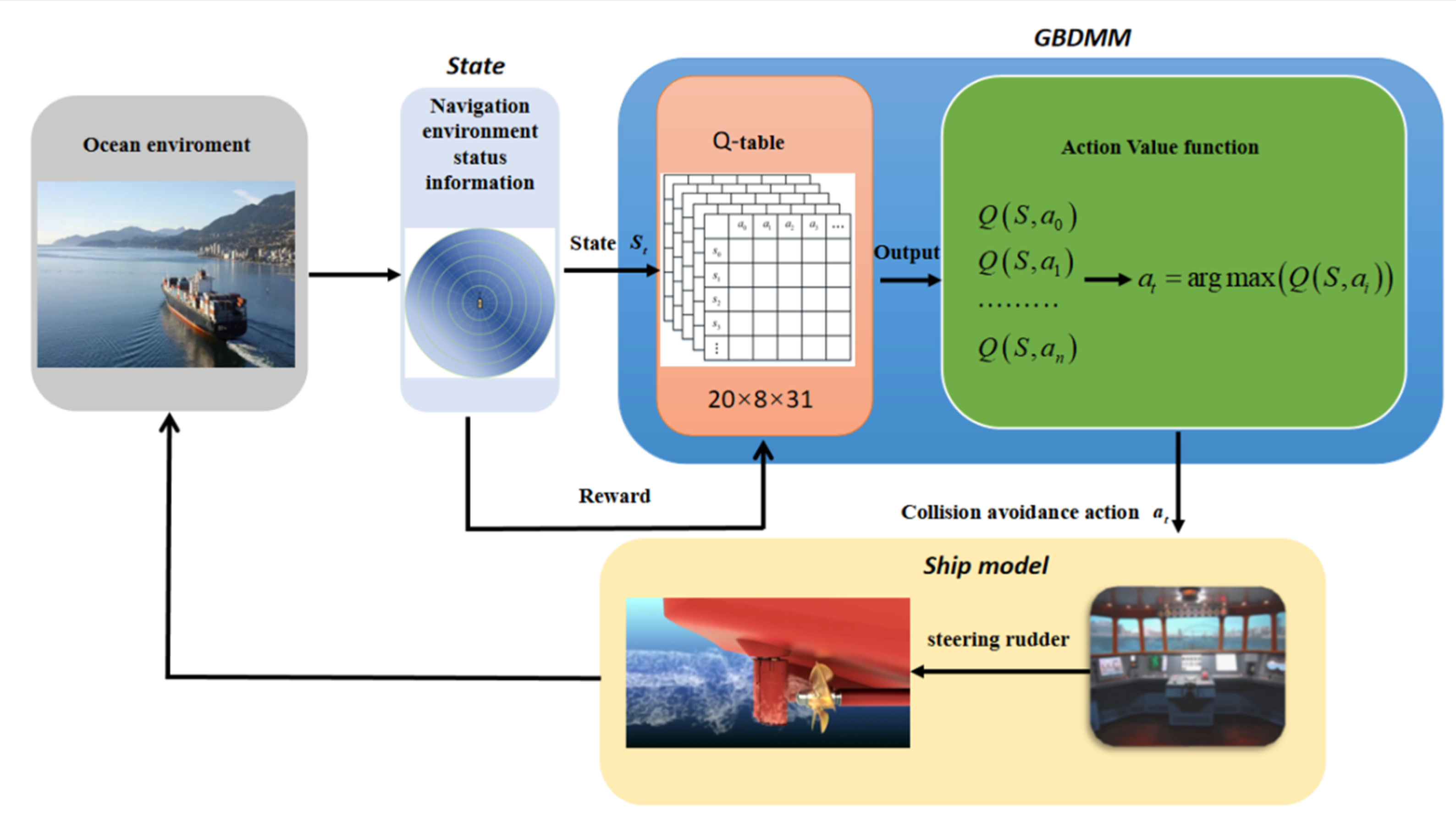
In this study, a GBDM model based on reinforcement learning, namely the Q-learning algorithm, is proposed. The grid sensor is quantified as the input of the RL algorithm, which reduces the input of observation states. The OZT algorithm is used for detection and clustering. In order to realize automatic collision avoidance of multiple ships, ship maneuverability is considered. The study also uses a three-degree-of-freedom (3-DOF) Nomoto ship motion mathematical model to simulate ship maneuvering, and the model’s action space is discrete rudder angles. This study also simplifies the reward function and introduces the navigation situation judgement to comply with the COLREGs. Finally, the trained GBDM model is only used in the collision avoidance behavior decision-making stage to improve the efficiency of the ship autonomous navigation system.
The organizational structure of this paper is as follows: Section 3describes the principle and application of reinforcement learning algorithm. In Section 4, the method of detecting collision risk is given firstly. Then, the ship motion model as the basis of ship collision avoidance is described. Furthermore, the design of the reward function is explained. Section 5 and Section 6 contain the simulation results of the multi-ship collision avoidance. In Section 7, we discuss the experimental results and potential applications. Section 8 is the conclusion of this paper.

3. Preliminary

3.1. Reinforcement Learning

The reinforcement learning is a branch of artificial intelligence. The concept of the Markov Decision Process (MDP) is introduced here. The reinforcement learning process is modeled as MDP quintuples, which consist of state, action, transition model, rewards, and policy. In a reinforcement learning model, decision-makers observe the environment and action according to the observation results and obtain rewards after action. Agent and environment receive maximum cumulative reward through real-time interaction mechanism and error judgment mechanism. Finally, the algorithm obtains the optimal action decision sequence through training. For the ship collision avoidance decision-making problem, the intelligent ship can select an action A according to the current state and receive reward R according to the interaction with the ship sailing environment. The intelligent ship selects the next action, according to the environment, based on the principle that the maximum reward value can be obtained by the intelligent ship [20].
As shown in Figure 1, the Q-learning algorithm in RL is applied to GBDM model. The reward signal received from the model is a reward given to the ship by the environment in the form of a function. The policy is the collision avoidance decision-making method. The choice of obstacle avoidance action is usually based on the policy function.
The Q-learning algorithm is an off-policy, so the action is determined by the action value function. The action value function is obtained by Q-table update iteration. The environment modeling process uses the ship motion model and the ship position transition probability model to predict the position and motion state of target ships and then calculates the observation state of the GBDM model at the next moment. The GBDM model observes the current observation state in the environment and then calculates the values corresponding to all the action spaces in the current observation state through the action value function. Finally, the GBDM model selects the action randomly or selects the action with the maximum action value function value in the exploration stage. In order to avoid falling into the local optimal, random selection selects the optimal action with probability P and randomly selects the action with probability 1 P according to the greedy strategy [21]. Then, the GBDM model takes action, and the environment updates the observation state and provides rewards to the agent through the reward function. At the same time, the GBDM model updates the action value function in the Q-table according to the relevant information. The action value function is updated as Equation (1). The GBDM model continuously circulates the above process until it reaches the waypoint or collides.
Q S , A = Q S , A + a R + γ max Q S , a Q S , A
where a is the learning rate. R is reward, and γ is discount factor. Q S , A represents the action value function of the current observation state. Q S , a represents the action value function of the next observation state.

3.2. Ship GBDM Model Design

The flow chart of the ship GBDM model via the reinforcement learning is shown in Figure 2. Firstly, we initialize the initial coordinates of the ship in the scenario. Then, the system calculates the relevant information and determines whether the OZT region enters the detection range of the grid sensor. If the target ships (TSs) do not enter the detection range of the grid sensor, the ship will continue to maintain its sailing course and speed. If the TSs enter the detection range of the grid sensor, it will determine whether the OS is a stand-on vessel. If the OS is a stand-on vessel, the OS will continue to maintain its heading; otherwise, the observation state is input into the GBDM model to make collision avoidance decisions. The resulting steering rudder combines the ship motion model to update the dynamic information of the ship. Finally, the model determines whether the end condition is satisfied: when the distance between the OS and the TS is less than the threshold (collision) or the distance to the target is less than the threshold without any collision risk (collision avoidance success), the ship is terminated; otherwise, the training cycle continues.

4. GBDM Model Design

4.1. The Concept of OZT

For clustering similar ship collision avoidance scenarios, the OZT is defined as a capsule-shaped area for the assessment of collision risk. The process of calculating OZT using the collision course C O is shown in Figure 3. Equation (2) could be used to calculate the collision course C o , which indicates the possibility of the OS’s collision with the target ship in the future [22].
C O = A Z ± a arcsin V T V O sin A Z ± a C T , A Z ± a π + arcsin V T V O sin ( A Z ± a C T ) , ( V T > V O )
where a = arcsin r s / d . r s is the safe passing distance, and d is the distance between the OS and the TS. V O is the OS’s speed, and V T is the TS’s speed. A Z is the azimuth of the TS’s position from the OS. C T is the course of the TS. When the ship is on a collision course, C O the relative motion is computed as follows.
Δ X = V T sin C T V O sin C O Δ Y = V T cos C T V O cos C O
V R = Δ X 2 + Δ Y 2 C R = arctan Δ X Δ Y
where V R and C R are the relative speed and course of the TS with respect to C O , respectively. Then, TCPA and DCPA for each C O can be obtained as follows.
D C P A = d sin C R A Z + π
T C P A = d cos C R A Z + π V R
When the ship is actually operating at sea, passing in front of the target ship is usually avoided. However, if the distance between the own ship and the target ship is large enough, it may pass in front of the target ship. This paper introduces a simple method to extend the area of the OZT via subtracting the safe passage distance from the bow crossing range. To detect the collision and bow crossing range corresponding to the OZT distribution, an additional area, such as the ship domain for collision detection, is defined.
As shown in Figure 4, the bow range is the area that is enclosed by the solid line, corresponding to the definition of OZT. When the OS enters the area of the TS, it will be judged as a collision. In this paper, the OZT area is a capsule-shaped area with a safe passage distance as the radius and the bow crossing range as 1.0 n mile.

4.2. Observation State

Since the input of the RL algorithm can only be a fixed-dimensional vector, the algorithm should be able to process multiple ships at the same time [23]. Therefore, in order to deal with this problem, we use a virtual sensor called the grid sensor to vectorize the predicted dangerous areas to ensure that the observation vectors can maintain the same dimension regardless of the number of TSs [24]. The diagrammatic drawing of using a grid sensor to detect the OZT is shown in Figure 5. The grid sensor extends from the center of the OS and is separated by a uniform angle and radius interval in the form of a polar grid. When the OZT overlaps with the grid cell, it is judged that the OZT is detected on the grid sensor.
If the OZT area overlaps with the grid cell, the component with the largest overlap area of the state vector is set to 1; otherwise, it is set to 0. Furthermore, if multiple grid cells completely overlap with the OZT, the state vector closest to the OS is set to 1, 0. As shown in Figure 5, the orange and blue capsule-shaped area represents the OZT, and the yellow zone represents OZT overlaps with the grid cell. The red cell represents the grid cell with the largest overlap area. Suppose the information of grid sensor is provided by AIS. Based on the practical range of shipborne AIS and the ship model used in this paper, the radius of the grid sensor could be determined [25]. Additional information about the grid sensor is shown in Table 2. Therefore, the input dimension of the proposed algorithm is designed as 20 × 8 .
Even more importantly, this method has the ability to cluster similar scenarios. As shown in Figure 5, the yellow ship represents the OS; the orange and blue ships and the capsule-shaped areas represent the TS and OZT, respectively. Figure 5 simulates the cross situation between the OS and two TSs. According to COLREGs, the OS and the two TSs all constitute a pair of two-ship crossing situations. Through this input observation method, it is obvious that the observation state between the OS and the two TSs is the same, indicating that the OS can identify the encounter situations with the two TSs as one, which improves the learning ability of the algorithm.
Remark 1.
In a previous study, Zhao et al. [14] proposed a total of 15 navigation parameters as the input of the model. This method could only consider one TS at each decision, resulting in limited applicable scenarios. Secondly, because the input of observation states completely used the actual navigation data, it would lead to the difficulty of model convergence. Woo et al. [17] proposed visual image information as input of observation states, which would also reduce the convergence speed of the model. Shen et al. [13] proposed a LiDAR-like detection line to collect environmental information, but there were also corresponding problems, as shown in Table 1. This paper improves the grid sensor proposed by Sawada as a state input [24]. The grid sensor is used to detect the surrounding navigation information, and the 20 × 8 matrix is formed by the one-hot encoding method as the state input of the model. The method proposed also solves the problem of complex input of observation states and can make decisions after considering multiple TSs.
Remark 2.
Compared with the grid sensor proposed by Sawada et al., an improved grid sensor is proposed in this paper, which is shown in Section 3.2 [16]. It can be used for RL models without deep neural networks and will reduce the quantity of the model parameters.

4.3. Action Space

As shown in Figure 6, a complete ship collision avoidance process usually includes four stages.
(1)
Environmental perception.
(2)
Collision avoidance behavior decision-making.
(3)
Course and speed changing/holding.
(4)
Planned route returning.
Figure 6. A complete ship collision avoidance process.
Jmse 11 00273 g006
However, the phase of obstacle avoidance behavior decision-making, which is the most important part of ship collision avoidance, requires the least time in the four processes.
In order to reduce the complexity of the model and improve the convergence of the RL algorithm, only the rudder angle is operated to steer the ship to avoid collision, which is a series of discrete steering instructions to change course. Thus, this paper uses the Nomoto three-degree-of-freedom (3-DOF) model [26]. The coordinated system of the ship motion and the ship principal dimensions are shown in Figure 7 and Table 3, respectively.
ψ ˙ = r r ˙ = K δ r / T δ ˙ = δ E δ / T X ˙ = V cos ψ Y ˙ = V sin ψ
The ship motion model can be expressed by Equation (7), where δ and δ E are the actual steering rudder angle and the command rudder angle, respectively, T E is the time constant of the steering gear, and V is the ship’s speed over ground.
In the process of ship collision avoidance operation, the collision avoidance actions, including steering course and changing speed, should be taken. However, in actual navigation, the high inertia of the ship makes it difficult to change the speed. Therefore, the RL algorithm’s action space is discrete rudder angles. If we define the port steering rudder as negative (-−) and starboard steering as positive (+) at intervals of 1 from 15 to + 15 , the action space is expressed as the following Equation (8).
a t 15 , , 0 , , + 15
Remark 3.
Woo and Guo et al. [15,17] proposed an RL model for decision-making in the entire collision avoidance process, which would also make the model difficult to converge. In this paper, the collision avoidance algorithm is only used in collision avoidance behavior decision-making stage (stage 2) and can reduce the computation burden of the ship autonomous collision avoidance system.

4.4. Reward Function

The reward function can be defined as the sum of accumulative rewards in each training episode, and its value is an important criterion for evaluating the action quality. The objective of this study is to maneuver the OS for collision avoidance while ensuring that the OS can arrive at the target point. Thus, the reward function should be defined to encourage the intelligent ship to travel to the target point and avoid collision with the TSs, while making the ship comply with COLREGs. However, the objectives of the two rewards are contradictory. When the OS is determined to avoid collision with the TSs, it will deviate from the traveling direction to the target point. To solve this problem, this paper defined the reward function by switching two modes: target driving and collision avoidance. Firstly, in the case of collision-free, the OS should maintain her course and sail to the target. If the collision danger scenario is as illustrated in Figure 5, the collision avoidance mode will be triggered, and TSs which are invading the grid sensor of the OS can be detected. Therefore, the four collision avoidance reward functions are used to update the action value function, as shown in Figure 8.
In collision avoidance situation, the goal reward function can drive the OS to the target point. The heading-error reward function can promote the OS to alter her course toward to the target point. The reward functions can be expressed mathematically as
R g o a l = ω × ( d o / V max )
θ = θ g o a l θ o , θ g o a l θ o > π / 3 0 , θ g o a l θ o π / 3
R θ = ( 0.5 2 × θ / π ) × ω h e a d
where ω is the guiding weight, d o is the distance between the current intelligent ship and the target point, V max represents maximum speed, θ represents the orientation of the target point, θ o is the current course of the ship, and ω h e a d represents the directional weight.
During the navigation, COLREGs should be complied by all marine vessels. Thus, this paper integrates the COLREGs into the reward function of the model [27]. It means that, during the model training, the OS should alter her course to starboard as much as possible when the OS needs to make collision avoidance decisions. The collision avoidance reward function, including collision reward function and COLREGs reward function, are defined as follows:
R a v o i d = 100 , ( x o x t ) 2 + ( y o y t ) 2 < 10 15 × ( x o x t ) 2 + ( y o y t ) 2 / 10 , 0 < ( x o x t ) 2 + ( y o y t ) 2 < 60
R r o t = ( 10 u + 0.01 ) × | Δ θ | , Δ θ < 0 0.01 × | Δ θ | , 0 Δ θ
where x o and y o are the coordinates of the OS, and x t , y t are the coordinates of the other TSs which are entering the safety detection range of the OS. Δ θ is the heading angle difference between the OS and the TS.

5. Simulation and Analysis

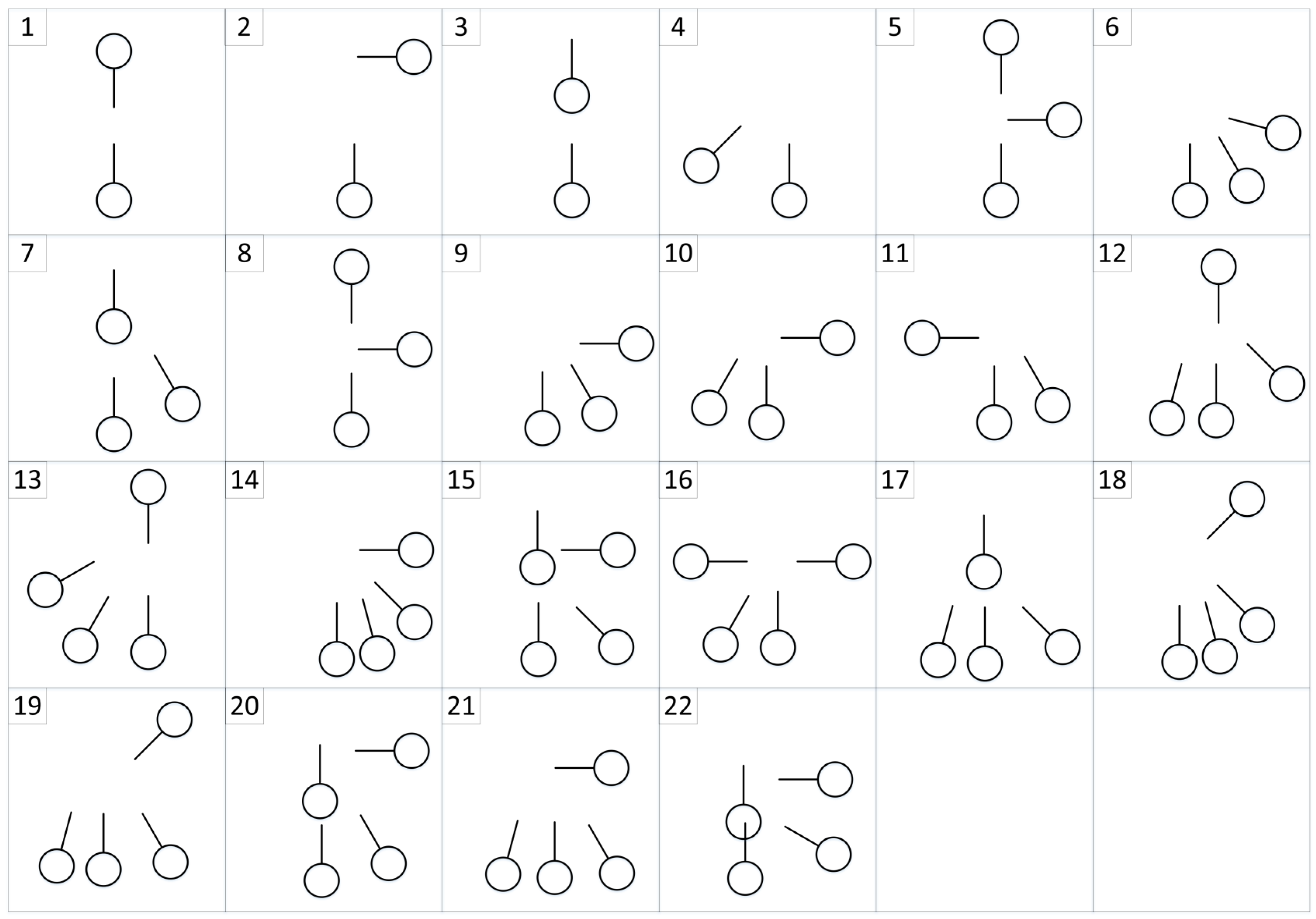
In this paper, it is assumed that the multi-ship encounter situations are at open sea without obstacles such as coastlines and buoys. The Imazu problem is treated as a learning scenario [28]. The Imazu problem includes basic one-to-one ship encounter situations and different multi-ship encounter situations. As shown in Figure 9, the number of cases for the Imazu problem is represented. Each circle represents the initial coordinates of the ship, and each bar represents the velocity vector of the ship. In addition, in order to improve the generalization performance of the GBDM model, this paper sets 60 different ship encounter situations based on the Imazu problem. The environment consists of OS and TSs. All intelligent ships in the encounter situations are intelligent ships and use the same GBDM model. The OS shall sail to the target points while avoiding target ships. Each intelligent ship updates the action value of the corresponding action on the Q-table during the training process. After finishing the multi-ship encounter situations training, the trained GBDM model (Q-table) is imported into the test environment to verify the training effectiveness. The test scenarios are shown in 
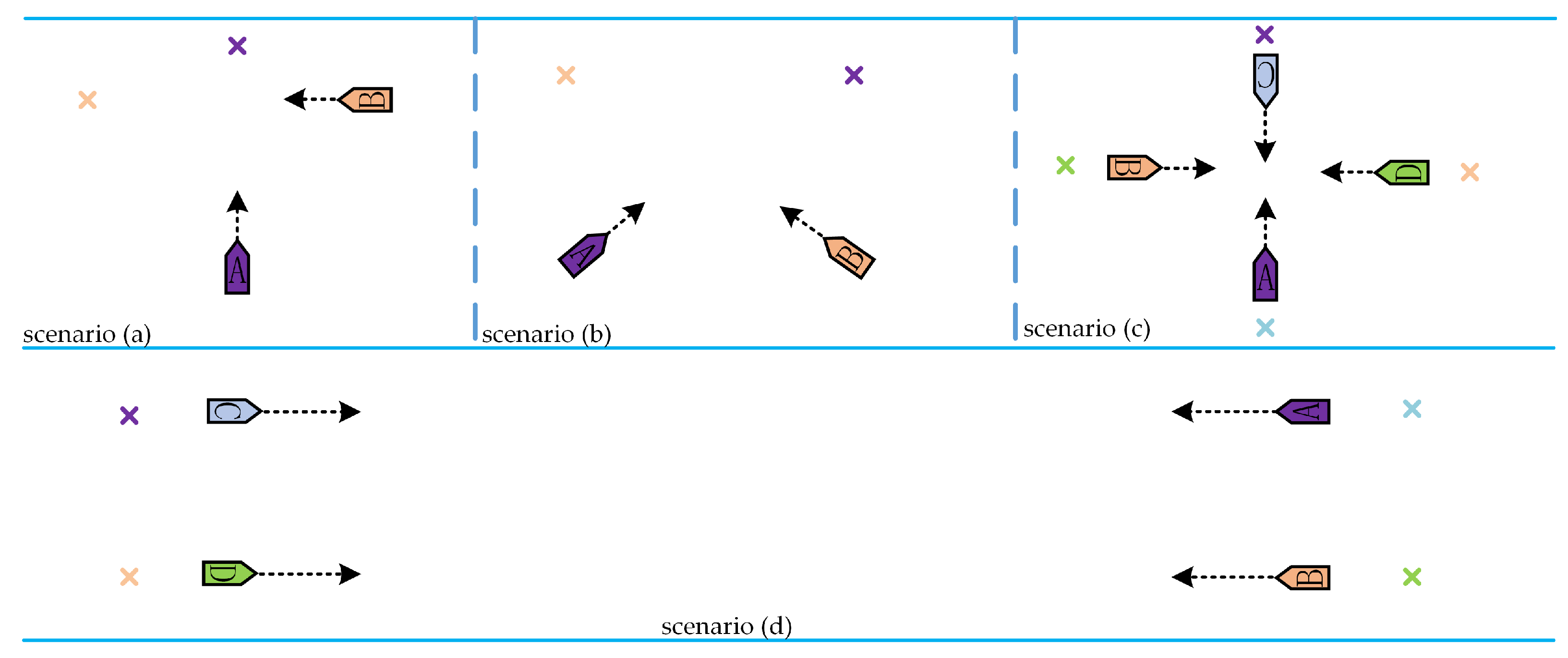
Figure 10. The four scenes contain two ship-to-ship crossing situations and two multi-ship encounter situations.
In this section, the training process based on the risk assessment of the COLREGs is presented. The intelligent ship is trained in 60 scenarios, and a total of 60 training environments are trained in one episode. Furthermore, each scenario is trained two rounds, and one round is trained 100 times. In order to test the trained GBDM model, scenario (a), scenario (b), scenario (c), and scenario (d) are simulated. The simulation scenario of the ship distribution is shown in Figure 10, and the coordinates of the ship starting and target points are shown in Table 4.
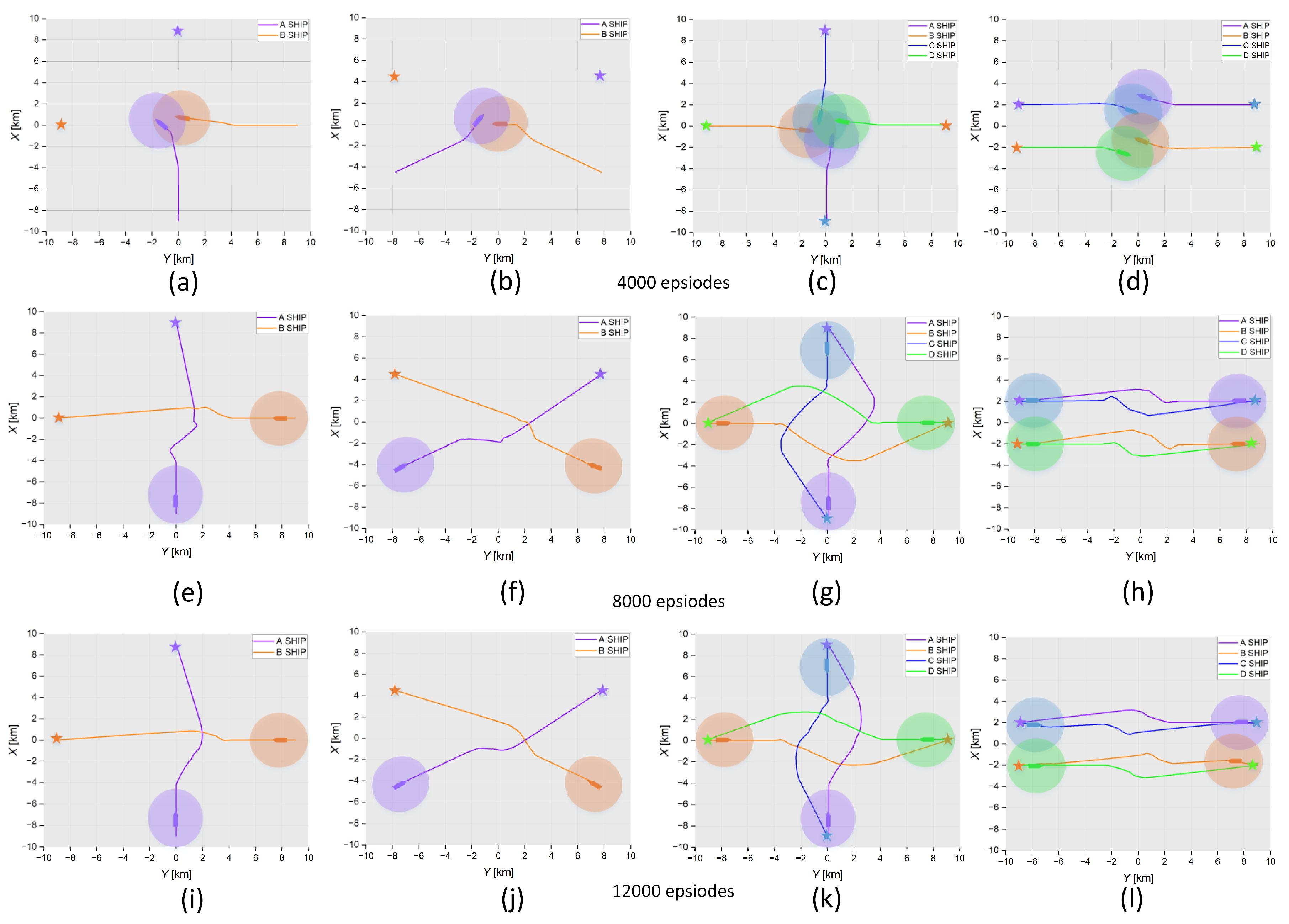
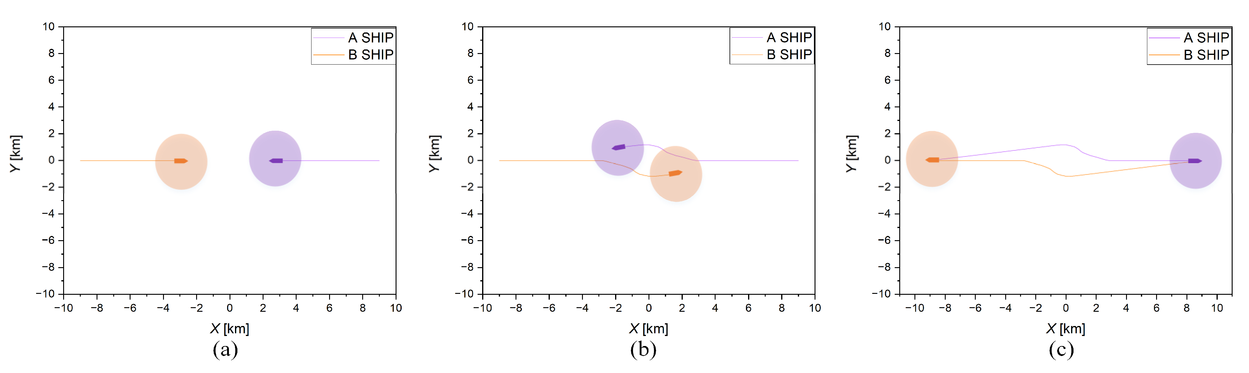
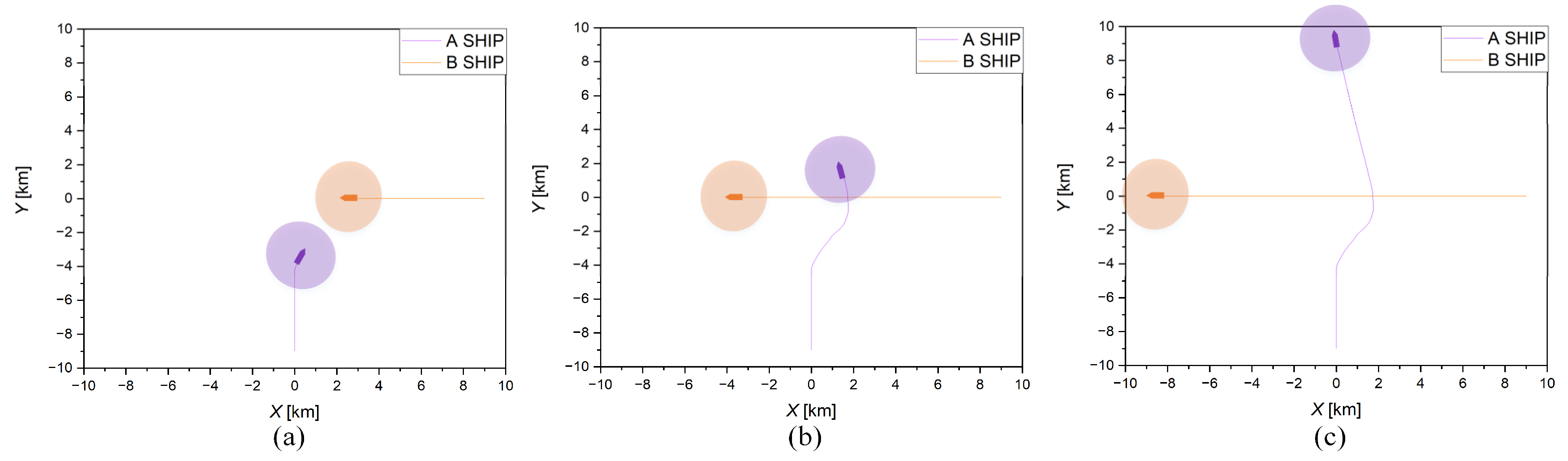
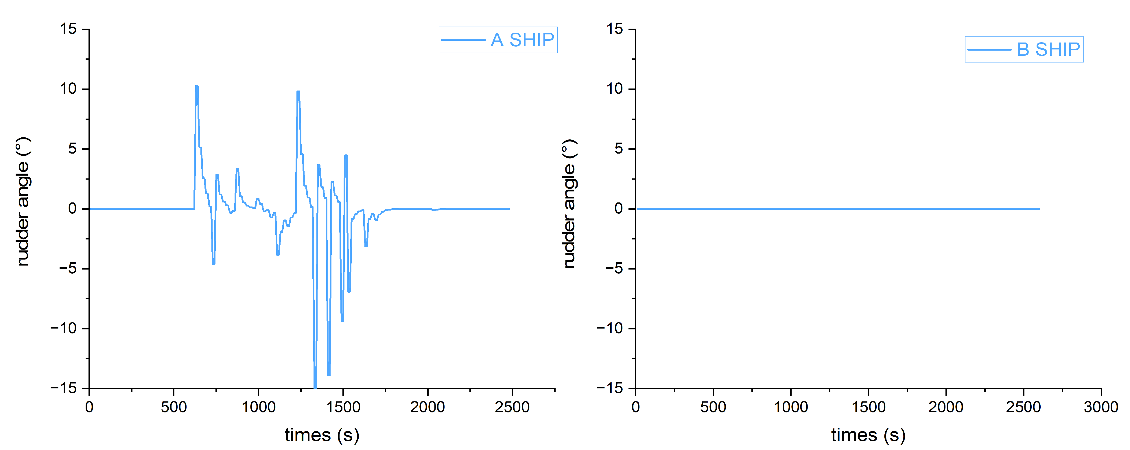
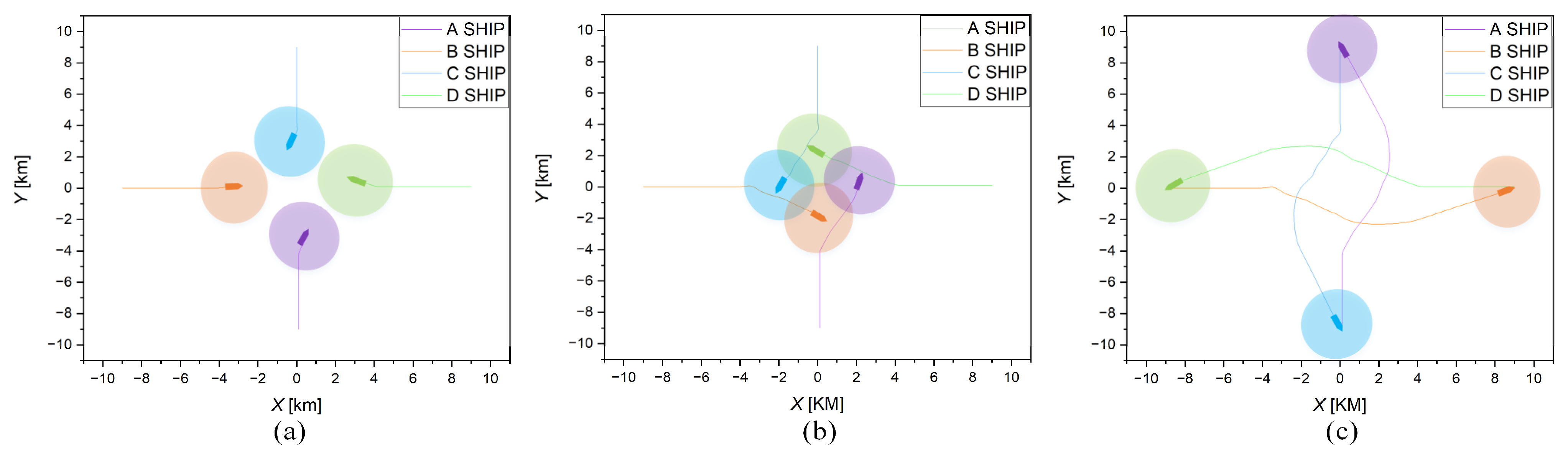
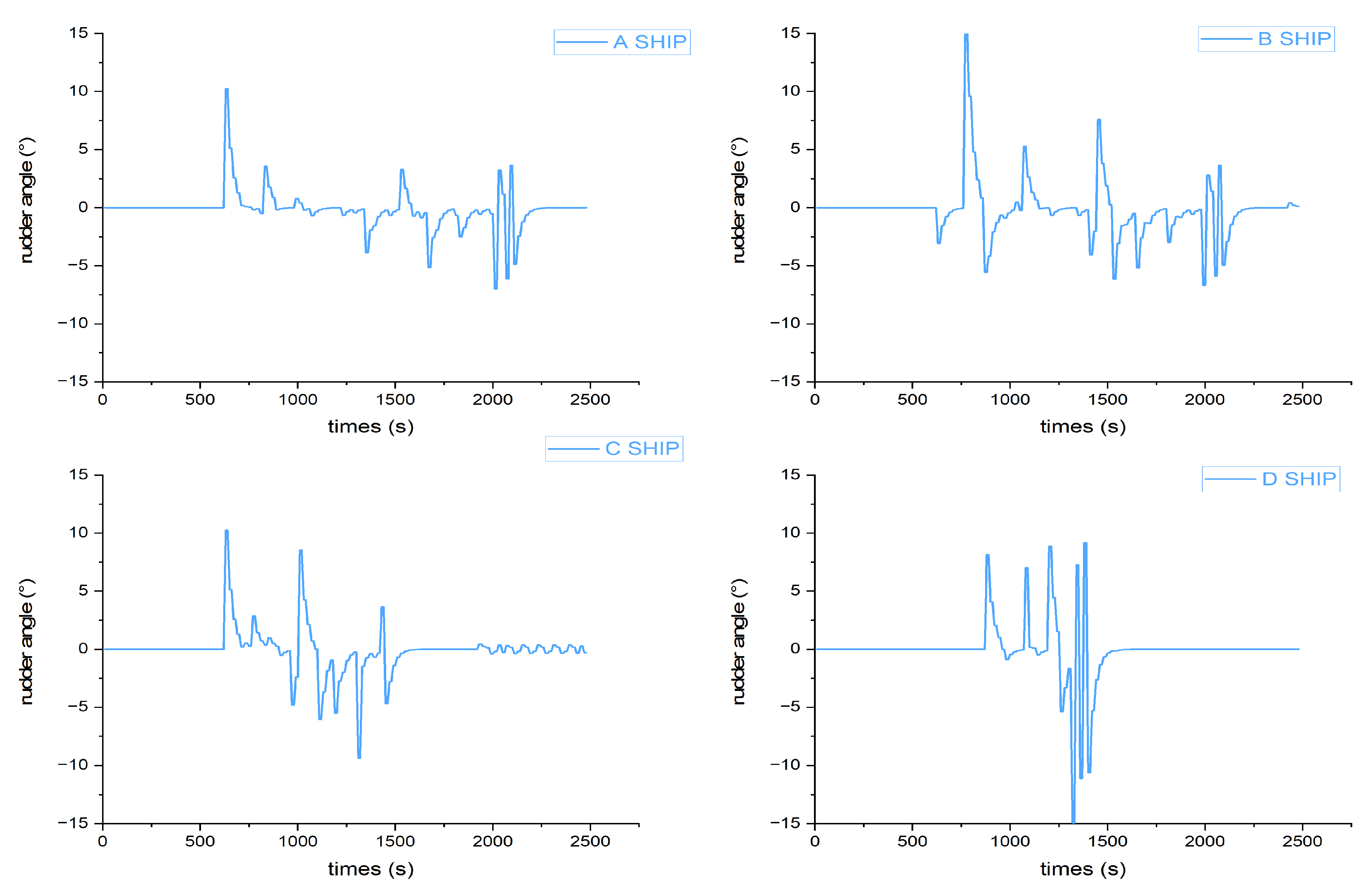
To inspect the effect of the GBDM model on the decision-making of ship collision avoidance after training different episodes, this paper conducted experimental simulation verification after training 4000, 8000, and 12,000 episodes in four scenarios, respectively. The results are shown in Figure 11. The four graphs in each row represent the results after different training episodes in scenarios (a–d). Scenario (a) is a two-ships head-on situation, scenario (b) is a two-ships crossing situation, and scenario (c) and scenario (d) are four-ships encounter situations. The initial settings of the ships in four different scenarios are shown in Table 4. The first four graphs (a–d) are the results of 4000 training episodes. It can be seen that the trained GBDM model could not pass the scenarios test. Graphs (e–h) are the results of 8000 training episodes. The trained GBDM model barely passes the scenarios test, the ships are oversteered, and the path is not smooth. It is indicated that the collision avoidance behaviors are not optimal. After 12,000 training episodes, the results are shown in graphs (i–l). It is obvious that the trained ship GBDM model can provide a better collision avoidance decision. The trained model scenarios tests demonstrate the GBDM model’s ability of safety navigation and collision avoidance, but it is necessary to further test and verify whether the trained model conforms to COLREGs.
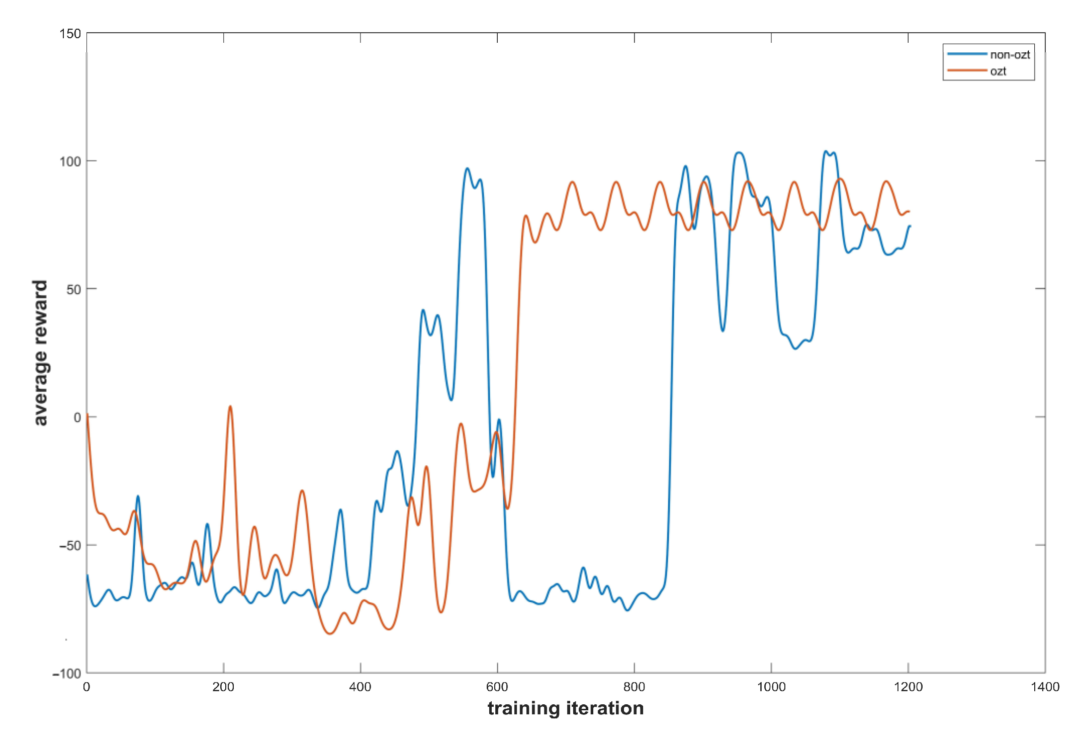
Figure 12 is the Q-learning algorithm comparison experiment results with and without the OZT. The orange line represents the average reward value per ten iterations with the OZT, and the blue line represents the average reward value per ten iterations without the OZT. It can be concluded that compared with non-OZT, the Q-learning algorithm can converge faster with the introduction of the OZT.

6. COLREGs Compliance Test

In order to verify whether the trained GBDM model comply with the COLREGs, a series of COLREGs compliance tests are conducted in different encounter scenarios. The performance evaluation of the ship collision avoidance GBDM model includes two aspects. The first is whether the collision avoidance action complies with the COLREGs, and the second is whether the ship can reach the target point with a collision-free path.

6.1. Two-Ship Encounter Situation

In order to make the GBDM model better conform to the rules, this paper introduces the concept of navigation situation as described in Table 5. As shown in Figure 13, the navigation information received by the sensor determines the avoidance responsibility of the ship through the navigation situation. If it is a stand-on ship, the speed and course will remain unchanged. If it is a give-way ship, observation state will be input into the GBDM model to output the steering rudder. Before the two ships encountering and making collision avoidance behavior decision, the give-way ship and the stand-on ship should be distinguished. As shown in Table 5 and Figure 14, according to the head-on situation in (COLREGs) rule 14 and the crossing situation in (COLREGs) rule 15, the give-way ship and the stand-on ship should be recognized. Additionally, according to the COLREGs, there is no distinction between a stand-on ship and give-way ship in the multi-ship encounter situations.
Remark 4.
Compared with the reward function in Shen, Li, Guo, and Woo et al., there are two main advantages in the proposed algorithm:
(1)
This paper designs a navigation situation judgement method, which will be more accurate in distinguishing between stand-on vessels and give-way vessels to comply with the rules.
(2)
We combine the recognition method based on the navigation situation with the bias starboard-side-alteration reward function Equation (13), which can comply with the COLREGs well and does not increase the complexity of the reward function.

6.1.1. Head-On Situation

According to COLREGs, there is no concept of the give-way ship and stand-on ship in the case of head-on. When collision avoidance is needed, the two ships should alter their courses to starboard, respectively. As shown in Table 6, the starting and target points of ship A are (−9, 0) and (9, 0), and those of ship B are (9, 0) and (−9, 0). The two ships sail in straight lines at 90° and 270°, respectively. In this situation, ship A and B are located in another ship’s head-on region. When collision avoidance operation is required, the two ships can maintain a speed of 7.5 m/s and alter their course to starboard to avoid collision. The simulation results are shown in Figure 15.
In Figure 15, the two ships are sailing in the head-on situation. At a distance of about 4 km, the two ships begin to alter course to starboard to avoid each other and pass port-to-port. As shown in Figure 16, the steering rudder angles of the two ships are almost the same in the process, both of which begin to steer at about the 750 s. The rudder angle varies from [−15°, 15°]. At about the 1500 s, the rudder angle is turned to 0°, and the two ships successfully complete the collision avoidance operation and drive toward to the target.

6.1.2. Crossing Situation

In the crossing situation, the ships should be distinguished between the give-way ship and the stand-on ship for compliance with COLREGs. As shown in Table 7, the initial coordinates of the two ships are (0, −9) and (9, 0), the target points are (0, 9) and (−9, 0), and the initial headings are 0° and 270°. The maximum speed is set to 7.5 m/s. The simulation results of the crossing situation are illustrated in Figure 17 and Figure 18.
In Figure 17, it can be seen that ship A is the give-way ship and ship B is the stand-on ship according to COLREGs. Therefore, when the two ships are close to each other and are required to avoid collision, ship B should maintain her heading and speed, and ship A should alter her course to starboard. Finally, ship A can pass safely from the stern of ship B and sail straight toward to the target point. As shown in Figure 18, ship B’s rudder angle remains at 0°, and ship A’s rudder angle starts to change at 650 s and returns to 0° after around 1650 s. The range of the steering rudder angle of ship A is [−15°, 15°].
From the above ship-to-ship encounter situations experiments, it can be seen that the trained GBDM model can take collision avoidance action well with the conformity to the COLREGs.

6.2. Multi-Ship Encounter Situation

As shown in Table 8, the initial coordinates of four ships are (0, −9), (−9, 0), (0, 9), and (9, 0), and the target points are (0, 9), (9, 0), (0, −9) and (−9, 0). The initial headings are 0°, 90°, 180°, and 270°. The maximum speed is set to 7.5 m/s. The simulation results of the multi-ship encounter situation are illustrated in Figure 19 and Figure 20.
As shown in Figure 19a, the four ships sail along the pre-determined straight line in the beginning. When the collision danger is detected, the four ships alter their course to starboard, respectively, to avoid each other. In Figure 19b, the four ships sail into a roundabout to avoid collision. In Figure 19c, the four ships advance toward the target point after passing each other. It is shown that when multiple ships encounter, the trained GBDM model can still provide each ship with an effective collision avoidance decision and drive her to the target point with the nearest route, complying with the COLREGs. Figure 20 illustrates the four ships’ steering rudder angle change.

7. Discussion

This study simplifies the input of observation states and improves the convergence rate by introducing grid sensors and OZT, as shown in Figure 11. The experimental results show that, with introducing the navigation situation into dividing the avoidance responsibility, the GBDM model can distinguish the give-way vessel and the stand-on vessel under the premise of complying with COLREGs as shown in Figure 16 and Figure 17. Furthermore, the input of observation states, the reward functions, and the action stages of the model are simplified by relevant methods in this paper. Finally, the experimental results demonstrate that the trained model can achieve multi-ship collision avoidance on the Imazu problem and converge faster. In some previous studies, Shen et al. [13], Zhao et al. [14], and Woo et al. [17] used complex input of observation states to perceive the surrounding navigation environment. By contrast, the method in this paper shows that using the grid sensor as the input of observation states can simplify the input and also well perceive the surrounding environment. In this paper, based on the improved grid sensor proposed by Sawada et al. [24], the observation state generated by the grid sensor can be applied to reinforcement learning without a complex neural network structure. In addition, in previous studies, Guo et al. [15] and Li et al. [19] designed complex reward functions to distinguish between the give-way vessel and the stand-on vessel. By contrast, this paper introduces the concept of navigation situation to judge the avoidance responsibility. The research results show that the GBDM model can distinguish between the give-way vessel and the stand-on vessel without increasing the complexity of the model. Compared with the previous experimental results, this paper improves the convergence speed of the model and obtains good experimental results in different collision situations.
The potential of this study is as follows: This paper provides a good research idea for designing a generalized ship collision avoidance decision-making model that complies with COLREGs without a complex reward function design. Since the proposed model is only used in the collision avoidance behavior decision-making stage, the proposed model has small computation burden. Due to the simple structure and low input dimension, the proposed GBDM model has strong real-time executive capability in the face of a complex navigation environment. In addition, the good convergence of the proposed GBDM model is highlighted. Future research is planned to use more complex scenarios and real marine traffic data to check the validity of the proposed model.

8. Conclusions

In this paper, an GBDM model via RL algorithm is proposed. Firstly, grid sensor detection OZT is used to reduce the complexity of GBDM model input information. Moreover, combining with the OZT detection technique and reinforcement learning algorithm, the proposed grid sensors can cluster the different ship-to-ship and multi-ship encounter situations. The convergence speed of the RL algorithm was also improved obviously. Furthermore, since the interaction between the designed GBDM model and the environment only occurs in the collision avoidance decision-making stage, the generalization and self-learning ability of the trained GBDM model is significantly improved. Moreover, the actions generated by the GBDM model can distinguish between a give-way ship and a stand-on ship without increasing the complexity of the model. Finally, a variety of collision avoidance scenario tests were carried out to evaluate the validity of the trained GBDM model. The simulation results indicate that the multiple ships could determine their collision avoidance actions simultaneously and in a timely manner to avoid each other and drive to the target point safely and effectively. In addition, it is prominent that the proposed method has a good generalization ability and can be applied to many different tasks, from ship-to-ship collision avoidance to multi-ship collision avoidance.
Although the method proposed in this paper can make collision avoidance decisions well in multi-ship encounters, there are still some problems to be explored in future research.
(1)
The ship detection area does not explore the stern area of the ship; thus, the ship’s overtaking situation has not been considered.
(2)
The interference of the ship navigation environment has not been considered in the collision avoidance decision-making model training, which might be necessary for practical implementation of the proposed method.

Author Contributions

Conceptualization, W.G.; methodology, M.-y.Z.; software, W.G., M.-y.Z. and Z.-y.X.; validation, C.-b.Z.; formal analysis, M.-y.Z. and C.-b.Z.; investigation, W.G. and M.-y.Z.; writing—original draft preparation, M.-y.Z. and W.G.; writing—review and editing, W.G. and Z.-y.X.; supervision, W.G.; project administration, W.G.; funding acquisition, W.G. All authors have read and agreed to the published version of the manuscript.

Funding

The paper is partially supported by National Natural Science Foundation of China (NO. 52171342) and Dalian Innovation Team Support Plan in the Key Research Field (2020RT08). The authors would like to thank the anonymous reviews for their valuable comments.

Institutional Review Board Statement

Not applicable.

Informed Consent Statement

Not applicable.

Data Availability Statement

The data that support the findings of this study are available from the corresponding author upon reasonable request.

Conflicts of Interest

The authors declare no conflict of interest.

References

  1. Statheros, T.; Howells, G.; Maier, K.M. Autonomous Ship Collision Avoidance Navigation Concepts, Technologies and Techniques. J. Navig. 2008, 61, 129–142. [Google Scholar] [CrossRef] [Green Version]
  2. Guan, W.; Peng, H.; Zhang, X.; Sun, H. Ship Steering Adaptive CGS Control Based on EKF Identification Method. J. Mar. Sci. Eng. 2022, 10, 294. [Google Scholar] [CrossRef]
  3. Lee, M.-C.; Nieh, C.-Y.; Kuo, H.-C.; Huang, J.-C. A collision avoidance method for multi-ship encounter situations. J. Mar. Sci. Technol. 2020, 25, 925–942. [Google Scholar] [CrossRef]
  4. Lyu, H.; Yin, Y. COLREGS-Constrained Real-time Path Planning for Autonomous Ships Using Modified Artificial Potential Fields. J. Navig. 2019, 72, 588–608. [Google Scholar] [CrossRef]
  5. Shaobo, W.; Yingjun, Z.; Lianbo, L. A collision avoidance decision-making system for autonomous ship based on modified velocity obstacle method. Ocean Eng. 2020, 215, 107910. [Google Scholar] [CrossRef]
  6. Liu, C.; Mao, Q.; Chu, X.; Xie, S. An Improved A-Star Algorithm Considering Water Current, Traffic Separation and Berthing for Vessel Path Planning. Appl. Sci. 2019, 9, 1057. [Google Scholar] [CrossRef] [Green Version]
  7. Krell, E.; King, S.A.; Carrillo, L.R.G. Autonomous Surface Vehicle energy-efficient and reward-based path planning using Particle Swarm Optimization and Visibility Graphs. Appl. Ocean Res. 2022, 122, 103125. [Google Scholar] [CrossRef]
  8. Wang, X.; Liu, Z.; Cai, Y. The ship maneuverability based collision avoidance dynamic support system in close-quarters situation. Ocean Eng. 2017, 146, 486–497. [Google Scholar] [CrossRef]
  9. Umar, M.; Amin, F.; Al-Mdallal, Q.; Ali, M.R. A stochastic computing procedure to solve the dynamics of prevention in HIV system. Biomed. Signal Process. Control. 2022, 78, 103888. [Google Scholar] [CrossRef]
  10. Garrote, L.; Temporão, D.; Temporão, S.; Pereira, R.; Barros, T.; Nunes, U.J. Improving Local Motion Planning with a Reinforcement Learning Approach. In Proceedings of the 2020 IEEE International Conference on Autonomous Robot Systems and Competitions (ICARSC), Ponta Delgada, Portugal, 15–17 April 2020; pp. 206–213. [Google Scholar]
  11. Long, P.; Fan, T.; Liao, X.; Liu, W.; Zhang, H.; Pan, J. Towards Optimally Decentralized Multi-Robot Collision Avoidance via Deep Reinforcement Learning. In Proceedings of the 2018 IEEE International Conference on Robotics and Automation (ICRA), Brisbane, QLD, Australia, 21–25 May 2018; pp. 6252–6259. [Google Scholar] [CrossRef] [Green Version]
  12. Ahmed, S.K.; Ali, R.M.; Lashin, M.M.; Sherif, F.F. Designing a new fast solution to control isolation rooms in hospitals depending on artificial intelligence decision. Biomed. Signal Process. Control 2023, 79, 104100. [Google Scholar] [CrossRef]
  13. Shen, H.; Hashimoto, H.; Matsuda, A.; Taniguchi, Y.; Terada, D.; Guo, C. Automatic collision avoidance of multiple ships based on deep Q-learning. Appl. Ocean Res. 2019, 86, 268–288. [Google Scholar] [CrossRef]
  14. Zhao, L.; Roh, M.-I. COLREGs-compliant multiship collision avoidance based on deep reinforcement learning. Ocean Eng. 2019, 191, 106436. [Google Scholar] [CrossRef]
  15. Guo, S.; Zhang, X.; Du, Y.; Zheng, Y.; Cao, Z. Path Planning of Coastal Ships Based on Optimized DQN Reward Function. J. Mar. Sci. Eng. 2021, 9, 210. [Google Scholar] [CrossRef]
  16. Sawada, R. Automatic Collision Avoidance Using Deep Reinforcement Learning with Grid Sensor. In Proceedings of the Symposium on Intelligent and Evolutionary Systems, Tottori, Japan, 6–8 December 2019; Springer: Cham, Switzerland, 2019; pp. 17–32. [Google Scholar] [CrossRef]
  17. Woo, J.; Kim, N. Collision avoidance for an unmanned surface vehicle using deep reinforcement learning. Ocean Eng. 2020, 199, 107001. [Google Scholar] [CrossRef]
  18. Chun, D.-H.; Roh, M.-I.; Lee, H.-W.; Ha, J.; Yu, D. Deep reinforcement learning-based collision avoidance for an autonomous ship. Ocean Eng. 2021, 234, 109216. [Google Scholar] [CrossRef]
  19. Li, L.; Wu, D.; Huang, Y.; Yuan, Z.-M. A path planning strategy unified with a COLREGS collision avoidance function based on deep reinforcement learning and artificial potential field. Appl. Ocean Res. 2021, 113, 102759. [Google Scholar] [CrossRef]
  20. Rebala, G.; Ravi, A.; Churiwala, S. An Introduction to Machine Learning; Springer: Berlin/Heidelberg, Germany, 2019. [Google Scholar]
  21. Mnih, V.; Kavukcuoglu, K.; Silver, D.; Rusu, A.A.; Veness, J.; Bellemare, M.G.; Graves, A.; Riedmiller, M.; Fidjeland, A.K.; Ostrovski, G.; et al. Human-level control through deep reinforcement learning. Nature 2015, 518, 529–533. [Google Scholar] [CrossRef]
  22. Imazu, H. Computation of OZT by using Collision Course. Japan Institute of Navigation. Jpn. Inst. Navig. 2014, 188, 78–81. [Google Scholar]
  23. Everett, M.; Chen, Y.F.; How, J.P. Collision Avoidance in Pedestrian-Rich Environments with Deep Reinforcement Learning. IEEE Access 2021, 9, 10357–10377. [Google Scholar] [CrossRef]
  24. Sawada, R.; Sato, K.; Majima, T. Automatic ship collision avoidance using deep reinforcement learning with LSTM in continuous action spaces. J. Mar. Sci. Technol. 2021, 26, 509–524. [Google Scholar] [CrossRef]
  25. Fukuto, J.; Imazu, H.; Kobayashi, E.; Arimura, N. Report of Field Experiments of AIS. Navigation 2002, 151, 73–78. [Google Scholar]
  26. Perez, T.; Ross, A.; Fossen, T. A 4-dof simulink model of a coastal patrol vessel for manoeuvring in waves. In Proceedings of the 7th IFAC Conference on Manoeuvring and Control of Marine Craft. International Federation for Automatic Control, Lisbon, Portugal, 20–22 September 2006. [Google Scholar]
  27. Zhao, Z.; Wang, J. Ship automatic anti-collision path simulations based on reinforcement learning in different encounter situations. Sci. Technol. Eng. 2018, 18, 218–223. [Google Scholar]
  28. Imazu, H. Research on Collision Avoidance Manoeuvre; Tokyo University of Marine Science and Technology: Tokyo, Japan, 1987. [Google Scholar]
Figure 1. Configuration of GBDM model via the reinforcement learning algorithm.
Jmse 11 00273 g001
Figure 2. Flow chart of GBDM model for collision avoidance.
Jmse 11 00273 g002
Figure 3. The concept of OZT.
Jmse 11 00273 g003
Figure 4. Domain for collision detection.
Jmse 11 00273 g004
Figure 5. Detection of OZT by the grid sensor.
Jmse 11 00273 g005
Figure 7. Coordinate systems used for ship motion description.
Jmse 11 00273 g007
Figure 8. The flow chart of the reward function value updates.
Jmse 11 00273 g008
Figure 9. Imazu problem.
Jmse 11 00273 g009
Figure 10. The trained GBDM model collision avoidance test scenario: (a) Crossing scenario, (b) Crossing scenario, (c) The scenario of four ships encountering, (d) The scenario of four ships encountering.
Jmse 11 00273 g010
Figure 11. The training process of ship collision avoidance GBDM model for the different test scenarios: (ad) 4000th episodes, (eh) 8000th episodes, (il) 12,000th episodes.
Jmse 11 00273 g011
Figure 12. Comparison of changes of the average reward during learning with and without OZT.
Jmse 11 00273 g012
Figure 13. Navigation situation judgment diagram.
Jmse 11 00273 g013
Figure 14. Encounter situations defined by COLREGs: (a) Head-on, (b) Crossing stand-on, (c) Crossing give-way.
Jmse 11 00273 g014
Figure 15. Collision avoidance in the head-on situation based on COLREGs: (a) Enter the obstacle avoidance decision-making stage, (b) Obstacle avoidance decision process, (c) Reach the target point.
Jmse 11 00273 g015
Figure 16. Steering rudder angle of ship A and ship B in a head-on situation.
Jmse 11 00273 g016
Figure 17. Collision avoidance with crossing situation based on COLREGs: (a) Enter the obstacle avoidance decision-making stage, (b) Obstacle avoidance decision process, (c) Reach the target point.
Jmse 11 00273 g017
Figure 18. Steering rudder angle of ship A and ship B in a crossing situation.
Jmse 11 00273 g018
Figure 19. Collision avoidance with four-ships encounter situation based on COLREGs: (a) Enter the obstacle avoidance decision-making stage, (b) Obstacle avoidance decision process, (c) Reach the target point.
Jmse 11 00273 g019
Figure 20. Steering rudder angle under four-ships encounter situation.
Jmse 11 00273 g020
Table 1. The Simple Summary of the Literature Review.
TypeReferenceTechniqueDisadvantages
COLREGs-compliant multi-ship collision avoidance based on DRL[13]DQN algorithm and detection line similar to LiDARThe detection line is radially extended and sparse, which makes it difficult to identify other long-distance ships and can only identify ships closer in the same direction.
[14]Policy-gradient based on DRL algorithmToo much observation state input leads to convergence difficulty.
[15]DQN algorithm and traditional reward function optimized in three aspectsRL model is applied to the entire collision avoidance process and might increase the state transition chain length and lead to an increase in computation complexity.
[16]DRL algorithm and virtual sensor based on OZTThere is no distinction between give-way vessels and stand-on vessels. In addition, designing a complex reward function to conform to the rules leads to slower convergence.
[17]DQN algorithm and DNN for identifying visual image informationUsing visual image information as input to DQN will result in excessive input of observation states, which will reduce convergence speed.
[19]Utilizing the APF algorithm to improve DRLThere is no distinction between give-way vessels and stand-on vessels and the input of observation state is excessive.
Table 2. Configurations of environment.
ParametersValue
Safe passing distance (km)0.5
Grid Sensor
Angle of detection (°)360
Grid space on angular direction (°)22.5
Radius of sensor (km)3
Grid space on radius direction (km)0.3
Table 3. Principal dimensions of the ship.
ParametersValue
Length (m)52.5
Beam (m)8.6
Draft (m)2.29
Rudder area (m2)1.5
Max rudder angle (deg)15
Max rudder angle rate (deg/s)10
Nominal speed (kt)15
K index−0.085
T index4.2
Table 4. The setting of GBDM model test scenarios: (a) Crossing scenario, (b) Crossing scenario, (c) The scenario of four ships encountering, (d) The scenario of four ships encountering.
ScenarioShip Start (km)Target (km)
Test scenario (a): A(0, −9)(0, 9)
B(9, 0)(−9, 0)
Test scenario (b): A(−8, −4.5)(8, 4.5)
B(8, −4.5)(−8, 4.5)
Test scenario (c): A(0, −9)(0, 9)
B(9, 0)(−9, 0)
C(0, 9)(0, −9)
D(−9, 0)(9, 0)
Test scenario (d): A(9, 2)(−9, 2)
B(9, −2)(−9, −2)
C(−9, 2)(9, 2)
D(−9, −2)(9, −2)
Table 5. The navigation situation understanding and division.
Target Ship OrientationRelative Bearing ψ t ψ o Responsibility
bow π 8 ~ π 8 7 π 8 ~ 9 π 8 give-way vessel
starboard π 8 ~ 5 π 8 π ~ 2 π give-way vessel
port 11 π 8 ~ 15 π 8 0 ~ π stand-on vessel
stern 5 π 8 ~ 11 π 8 3 π 2 ~ 2 π stand-on vessel
Table 6. Head-on situation.
ShipStartTargetHeading
A(−9, 0)(9, 0)90°;
B(9, 0)(−9, 0)270°
Table 7. Crossing Situation.
ShipStartTargetHeading
A(0, −9)(0, 9)
B(9, 0)(−9, 0)270°
Table 8. Multi-ship encounter situation.
ShipStartTargetHeading
A(0, −9)(0, 9)
B(−9, 0)(9, 0)90°
C(0, 9)(0, −9)180°
D(9, 0)(−9, 0)270°
Disclaimer/Publisher’s Note: The statements, opinions and data contained in all publications are solely those of the individual author(s) and contributor(s) and not of MDPI and/or the editor(s). MDPI and/or the editor(s) disclaim responsibility for any injury to people or property resulting from any ideas, methods, instructions or products referred to in the content.

