Article

The Analysis of Cavitation Flow and Pressure Pulsation of Bi-Directional Pump

1
College of Hydraulic Science and Engineering, Yangzhou University, Yangzhou 225000, China
2
Yangzhou Survey Design Research Institute Co., Ltd., Yangzhou 225000, China
*
Author to whom correspondence should be addressed.
J. Mar. Sci. Eng. 2023, 11(2), 268; https://doi.org/10.3390/jmse11020268
Submission received: 20 December 2022 / Revised: 3 January 2023 / Accepted: 16 January 2023 / Published: 24 January 2023
(This article belongs to the Special Issue CFD Analysis in Ocean Engineering)

Abstract

:
A bi-directional pump is designed by using S-shaped hydrofoil, is the most convenient way to achieve bi-directional operation. In this paper, high-speed photography is used to visualize the flow field characteristics of the bidirectional pump under different cavitation numbers, and the flow field changes caused by cavitation are quantitatively analyzed in combination with the pressure pulsation sensor. The results show that the operation efficiency of the bidirectional pump in reverse operation is lower than that in forward operation. Tip clearance cavitation occurs on both suction and pressure surfaces of the impeller under reverse operation and large flow. In reverse operation, the influence of guide vane on the main frequency of pressure pulsation in the impeller is obvious. The quasi-periodic vertical cavitation flow phenomenon increases the amplitude of pressure pulsation in the impeller and becomes the main component of the internal flow in the bidirectional axial flow pump.

1. Introduction

Axial flow pumps are mainly used for long-distance water transport, urban drainage, and agricultural irrigation [1,2,3].The bi-directional axial flow pump is a special type of axial flow pump, which has the properties of axial flow pump, but in reverse operation, and can obtain higher operation efficiency than the unidirectional axial flow pump. The bi-directional axial flow pump is designed by using a centrally symmetrical S-shaped hydrofoil [4,5], and the different direction of the axial flow pump can be switched only by adjusting the motor steering, which is the most convenient way to realize the bi-directional operation, and can save a lot of human resources and energy [6].
Cavitation is the main factors restricting the development of rotating machinery to with high speed and high performance [7,8]. Since the 19th century, the existence of cavitation has been found in experiments with propellers. Until today, cavitation is still a difficult problem to solve in the field of hydraulic machinery. There are different ways of cavitation movement in different hydraulic machinery [9]. Tip clearance cavitation is mainly driven by the pressure difference between the suction surface and the pressure surface, which widely exists between the stator and rotor of high-speed rotating hydraulic machinery [10]. Arndt et al. [11] tested the cavitation flow phenomenon inside a turbine. Wu et al. [12] used Particle Image Velocimetry (PIV) technology to test the tip leakage vortex (TLV) of a water-jet propulsion pump. The results showed that the tip leakage flow moved in the form of jet flow, and the evolution characteristics of various staggered vortex structures were determined through a large number of detailed data. Zhang et al. [13,14,15] performed study on an axial-flow pump with a specific speed of 728, using high-speed photography to capture the evolution of TLV, and used the modified SST (Shear Stress Transport) turbulence model combined with the Zwart cavitation model to simulate the cavitating flow, revealing the interaction mechanism of TLV and SSPCV. Hao et al. [16] studied the transient cavitating flow of PAT (pump as turbine) in pump mode by combining experiment and numerical simulation, quantitatively analyzed the cavitation performance in pump mode caused by clearance size variation, and compared the radial force variation under different sizes of tip clearance. Li et al. [17] studied the cavitation phenomenon inside the pump-turbine, adopted the entropy production theory to analyze the flow loss caused by the cavitation phenomenon in the S characteristic region, and found the hysteresis characteristics of the flow loss in the hump region of the pump turbine. Shen et al. [18,19] studied the instantaneous development process of vertical cavitation vortices through high-speed photography combined with the synchronous measurement of pressure sensors. It was found that tip cavitation vortices caused blockage in the impeller passage, and the correlation between the transient motion of SSPCV and the flow instability of the axial flow pump under the condition of low flow rate was confirmed. Shi et al. [20] studied the energy conversion changes of a spiral multiphase pump under different cavitation conditions, and discussed the changes of turbulence loss and friction loss under three different cavitation numbers (initial cavitation, critical cavitation, and severe cavitation). Wang et al. [21] studied the correlation characteristics of cavitation flow and vortex, and used the vorticity transport equation to analyze the evolution of a vortex induced by cavitation in tip clearance of the axial-flow pump.
In order to suppress or delay the instability of flow caused by the tip leakage vortex, researchers began to use control methods at the position of tip clearance. The current control methods are mainly passive control to improve the shape of tip clearance structure. There are many excellent passive control methods in the field of axial fan [22,23,24], which mainly suppress the influence of TLV by changing the shape of the blade tip and improve the operating performance of fluid machinery. Tan et al. [25] adopts T-shaped structure to successfully suppress the tip clearance vortex of the mixed flow pump, reduce the leakage flow in the tip area, and improve the efficiency of the mixed flow pump. Liu et al. [26] used C-shaped grooves at the tip clearance to study the influence of C-shaped grooves of different sizes on TLV, which effectively improved the lift coefficient of NACA0009. Nazir et al. [27,28,29,30,31] take ethylene glycol with nanoparticles behaves as the research object and consider the importance of temperature gradient in studying fluid behavior.
At present, the research of bidirectional axial flow pump mainly focuses on the design optimization and energy performance of the base hydrofoil [32,33,34]. The research on the cavitation phenomenon of bidirectional axial flow pump has not been reported. Due to the particularity of the base airfoil forming the bidirectional axial flow pump, the cavitation characteristics of the bidirectional axial flow pump are bound to be different from that of a conventional axial flow pump. Therefore, through high-speed photography combined with a pressure pulsation sensor, this paper studies the correlation between cavitating flow and pressure pulsation change of a bidirectional axial flow pump under different directions, different flows, and different cavitation numbers, providing theoretical guidance for the cavitation research and application of a bi-directional axial flow pump.

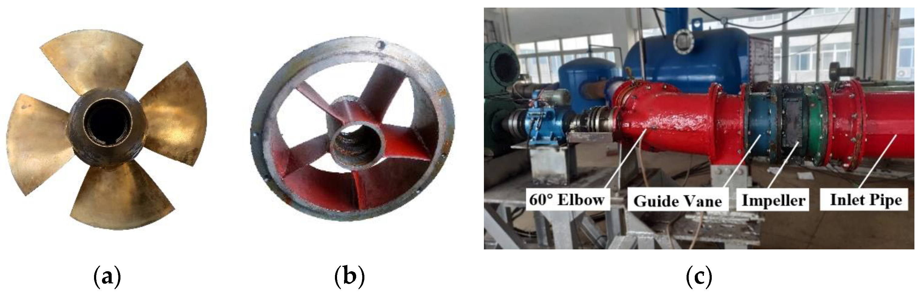
2. Experimental Setup

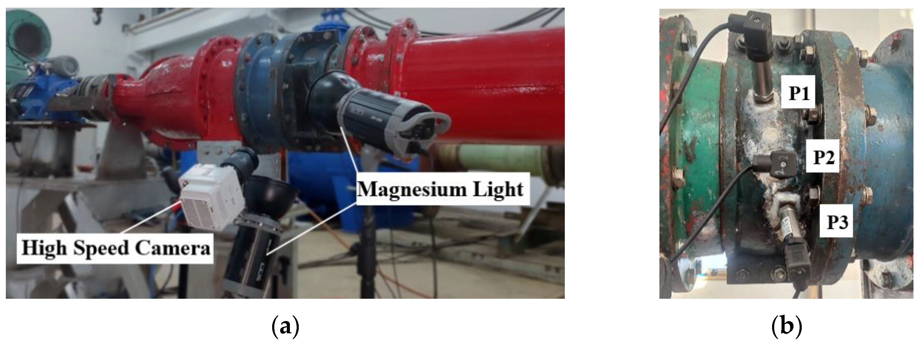
2.1. Experimental Platform

Cavitation experiment of the bi-directional pump was completed in Jiangsu Provincial Key Laboratory of Hydraulic Power. The experimental platform can realize the operation of the bidirectional pump in different directions, which is completely consistent with the application in practical engineering, and the energy performance and cavitation characteristics of the different directions can be recorded. The experimental platform is mainly composed of a test pump section, stainless steel pipe, water tank, and driving pump, etc., as shown in Figure 1. The maximum rotational speed of the test axial flow pump can reach 1500 revolutions per minute. Cavity occurs through a vacuum pump to continuously reduce the inlet pressure. The experimental platform is also equipped with an auxiliary pump for circulating water movement. The number of bi-directional axial flow pump blades is four, and the number of guide vane blades is five. In order to facilitate high-speed photography, about 1/4 of the area of the shroud is transparent glass instead of stainless steel, which is convenient to observe the cavitating flow at the tip clearance. The parameters of the bidirectional pump in this study are shown in Table 1. The impeller of the bi-directional pump is shown in Figure 1a, the guide vane is shown in Figure 1b, and the pump section is shown in Figure 1c.

2.2. Instrument and Its Precision Analysis

The models, parameters, and accuracy of the instruments are shown in Table 2. The performance of the bi-directional pump were collected by experimental instruments, among them, the head is collected by differential pressure transmitter, the measuring instrument model is EJA110A, and the shaft power is collected by speed torque sensor, and the measuring instrument model is JC2C. The inlet flow rate is recorded by an electromagnetic flowmeter, the measuring instrument model is E-mag, and the pressure of the experimental system is recorded by absolute pressure transmitter, and the measuring instrument model is EJA110A. The image of cavitation flow was captured by a VEO710L high-speed camera with a camera frequency of 7400 f/s. The cavitation experimental device is shown in Figure 2a. Three HM90A pressure pulsation sensors are installed in the shroud of the impeller. The installation position of the sensors is shown in Figure 2b, and the sampling frequency is 3000 Hz.
Both the cavitation external characteristic experiment and the high-speed photography experiment are repeated for many times. Among them, the external characteristic experiment ensures that the error of the flow head and shaft power of the multiple experiments is within 0.39%. For repeated testing of high-speed photography, cavitation photos of multiple tests are selected for comparison to ensure the same cavity volume and motion form.
The accuracy of the experimental platform is mainly determined by the accuracy of various instruments, and the formula is shown in Equation (1). According to the uncertainty of each instrument in Table 2, the comprehensive uncertainty can be calculated as Equation (1) and, the value is ±0.39%.
E System = E D 2 + E E 2 + E S 2 + E A 2 + E P 2
where, E System represents the system uncertainty of the test bench of the axial flow pump. E D represents the uncertainty of the differential pressure transmitter,   E E represents the uncertainty of the electromagnetic flowmeter, E S represents the uncertainty of the Speed and torque sensor, E A represents the uncertainty of the absolute pressure transmitter,   E P represents the uncertainty of the pressure transmitter

3. Results and Analysis

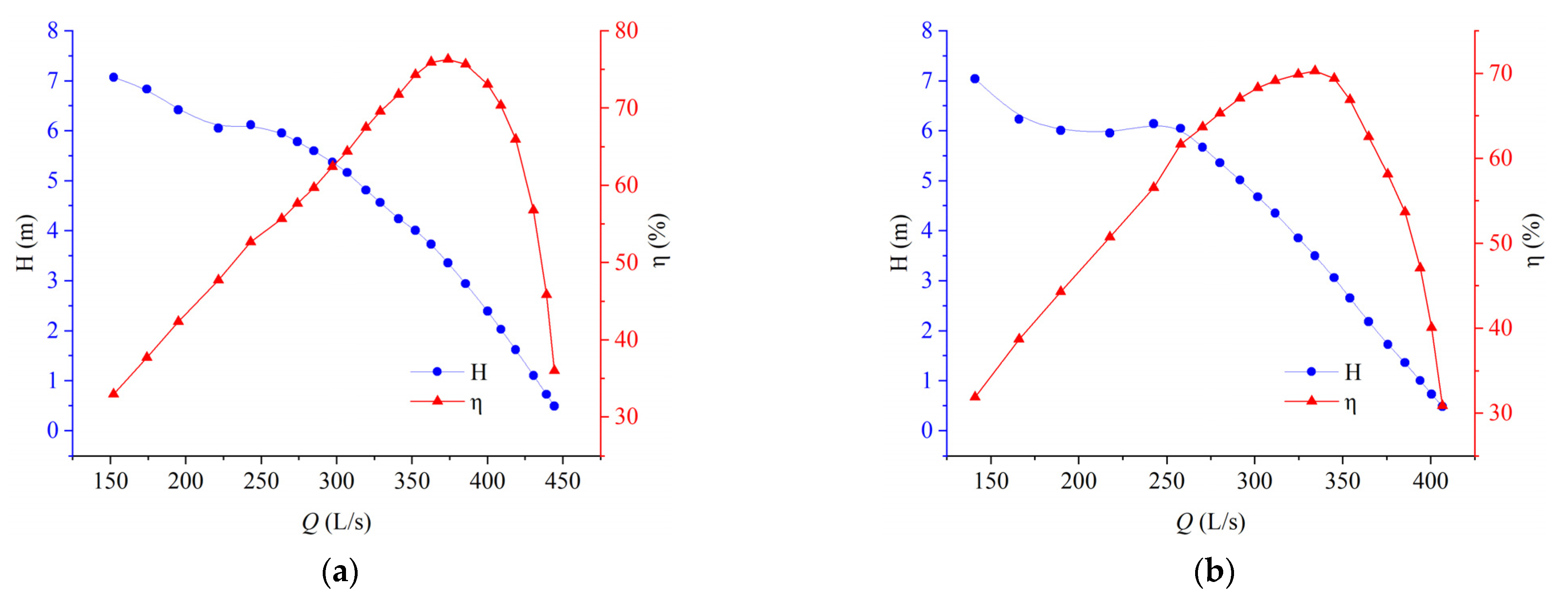
3.1. Energy Performance of Bi-Directional Pump

Energy performance is the basis of using bi-directional pumps. According to the data collected by various instruments, the forward and reverse efficiency can be calculated, and the formula is as Equation (2).
η =   ρ gQH P w
where, Q presents the flow rate; H presents the head; P w presents the shaft power.
In the forward operation, the water first passes through the impeller and then through the guide vane, which is the same as the operation mode of the conventional axial flow pump. As is shown in Figure 3, under the forward operation, the maximum operation efficiency of the bi-directional pump is 76.31%, and the corresponding flow rate and head are 374 L/s and 3.51 m, respectively.
In the reverse operation, the direction of rotation of the impeller is opposite to that in the forward operation. The maximum operation efficiency of the two-way pump is 70.29%, and the corresponding flow rate and head are 334 L/s and 3.51 m, respectively. From the view of axial-flow pump design theory, the impeller designed with a symmetric S-shaped hydrofoil should have exactly the same hydraulic performance in the forward operation and reverse operation. However, compared with the forward operation, the reverse operation has a lower maximum operating efficiency, and the overall flow is smaller. The main reason for this phenomenon is the position of the guide vane. In reverse operation, the water will first pass through the guide vane and then through the impeller. The flow angle at the inlet of the impeller will change due to the diversion effect of the guide vane. Secondly, there is no rearward guide vane recovery circulation, which will cause the flow disorder in the inlet flow channel, increase the hydraulic loss, and decrease the maximum efficiency of reverse operation. In forward operation, the saddle zone occurs at 0.65 Qd, while in reverse operation, the saddle zone occurs at 0.72 Qd. However, the flow in forward operation and reverse operation stall is the same, both at 242 L/s, indicating that the axial flow pump stall is related to the change of the angle of attack of the hydrofoil caused by the inlet flow rate and the inlet velocity, but has little correlation with the forward operation and reverse operation.

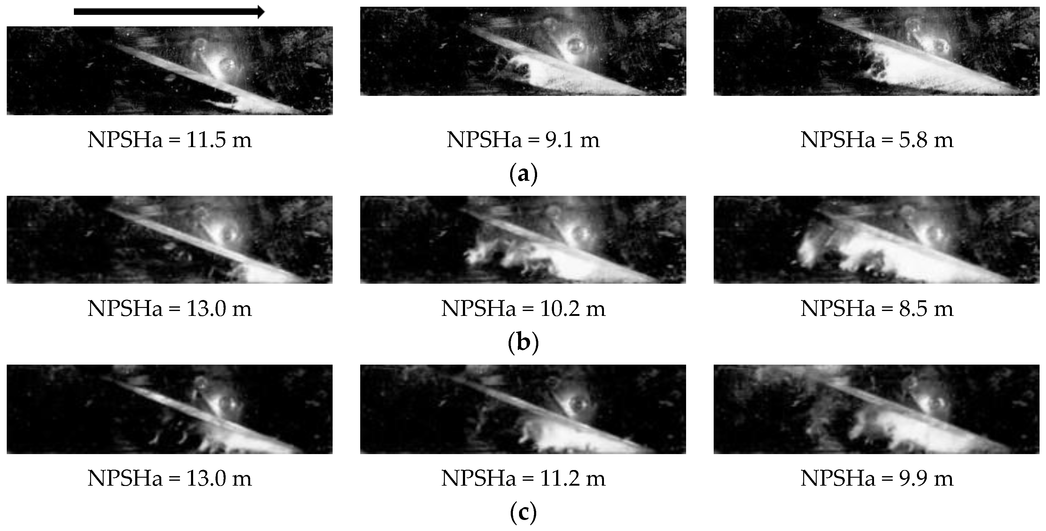
3.2. Analysis of Cavitation Performance of Bi-Directional Pump

The cavitation of the bi-directional pump has different flow characteristics under different flow conditions. Three groups of high-speed photography with different flow rates and three groups of different cavitation numbers (initial cavitation, critical cavitation, and severe cavitation) were selected for analysis.
a. Forward operating condition
During forward operation, it can be seen from the cavitation image from Figure 4 that tip clearance cavitation is relatively stable under large flow conditions, and tip clearance cavitation forms a triangular area with blade edge. With the decrease of cavitation number, the volume of tip clearance cavitation area increases continuously. Under the condition of severe cavitation, the tip clearance cavitation is stable and the shedding at trailing edge is less. Under the condition of design flow rate and the lower flow rate, the volume of unstable shedding cavitation at the trailing edge of cavitation increases, the instability degree of cavity movement at the tip clearance increases, and the quasi-periodic cavitation shedding phenomenon is induced. Velocity and Angle of attack are the main factors that cause the cavity to produce unstable shedding. The decrease of flow rate leads to the change of inlet velocity triangle, which is equivalent to the increase of the Angle of attack of the hydrofoil. It is the main reason that the bidirectional axial flow pump produces an unstable shedding structure under the condition of lower flow rate.
b. reverse operating condition
By adjusting the rotation direction of the motor and changing the rotation direction of the impeller, the reverse operation of the axial flow pump can be realized. Figure 5 is the cavitation motion image under different cavitation numbers in reverse operating condition. It can be seen from the Figure 5 that, under the condition of large flow, the cavitation is mainly in the form of the tip clearance vortex in the initial cavitation stage. As the inlet cavitation number decreases, the area between the tip clearance and tip cavitation is filled the by cavitation bubble.
Under severe cavitation conditions, the cavity also exists on the pressure surface of the impeller, which is different from the cavitation phenomenon of tip clearance in other unidirectional axial flow pumps. According to the analysis, it is mainly due to the special pressure distribution of the basic S-shaped hydrofoil [35]. Under the condition of a large flow rate, the angle of attack of the S-shaped hydrofoil is close to zero, and the reverse pressure difference generated in the latter part drives the water flow to form a new clearance cavity on the pressure side. With the decrease of flow rate, the area of tip clearance cavitation increases continuously in the design flow condition and the lower flow rate, and the volume of unstable shedding cavity increases gradually. Under the condition of lower flow rate, the instability degree of the cavity increases, and quasi-periodic large volume cavitation clouds fall off and move along the tip, forming a vertical cavitation phenomenon.

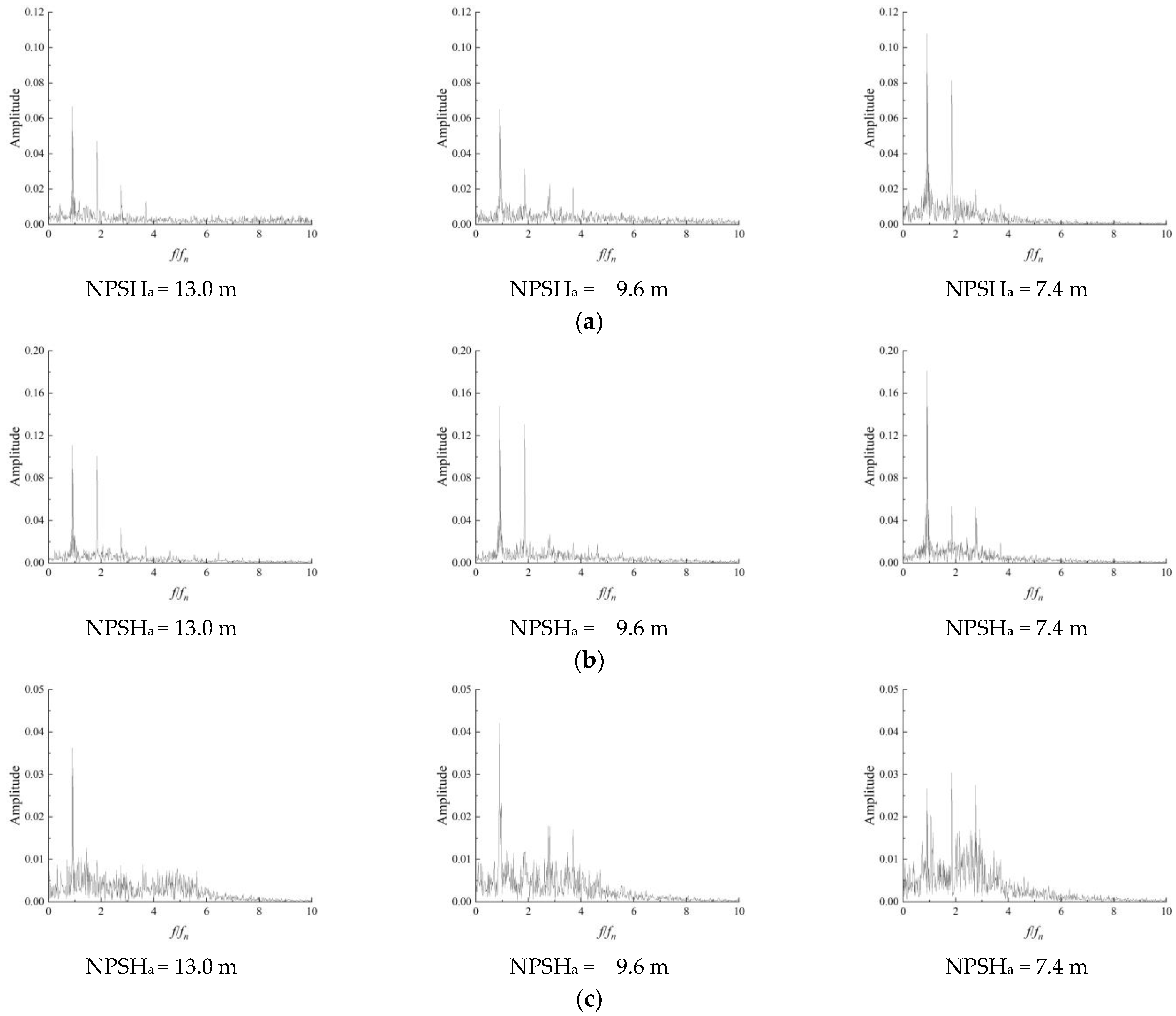
3.3. Pressure Pulsation Analysis under Cavitation Condition

a. Forward rotation
The pressure pulsations at tip clearance locations under different cavitation numbers were collected by a pressure sensor. The pressure pulsation coefficient can be calculated by the formula as Equation (3).
Cp = P P ¯ 0.5 ρ u 2
where P presents the pressure, P ¯ presents the average pressure, ρ presents the density, u presents the velocity.
As can be seen from Figure 6, under the condition of a large flow rate and without cavitation, the pressure pulsation has multiple peaks within one circle of impeller rotation. With the decrease of cavitation number, under the critical cavitation condition and severe cavitation condition, the variation of the pressure pulsation peak is small, and the multiple wave peaks gradually disappear and become a single wave peak. Although cavitation will inevitably cause material damage, it also restrains the high frequency variation of pressure pulsation. Under the condition of the lower flow rate, the inlet position of the impeller can still maintain a good variation law, but in the impeller and impeller outlet, the unstable movement of cavitation causes more complex changes in pressure pulsation. In general, in the forward operation, except for the lower flow condition, the pressure pulsation at the inlet of the impeller changes regularly, and with the decrease of cavitation number, the pressure pulsation regularity becomes more obvious and changes smoothly.
b. reverse rotation
In reverse operation, P1 is the impeller outlet and P3 is the impeller inlet. As can be seen from Figure 7, similar to the forward operation, the pressure pulsation changes at different positions have good regularity under design flow rate and large flow rate, but the pressure pulsation changes at the impeller outlet are complex under a lower flow rate. Different from the forward operation, with the decrease of cavitation number; The pressure pulsation amplitude increases gradually under high flow conditions, while cavitation can suppress the pressure pulsation amplitude during forward operation. Under different cavitation numbers, the pressure amplitude of the design flow rate is the largest, and the pressure amplitude of the middle of the impeller exceeds the inlet and outlet of the impeller. When large-scale cloud cavitation does not occur, relatively stable cavitation can suppress unstable pressure pulsation. However, after large-scale cloud cavitation occurs, the instability degree of pressure pulsation data increases and becomes more complex.

3.4. Analysis of Unstable Signal of Cavitation

From the visualization image of cavitating flow, it can be found that at a small flow rate, vortex cavitation caused by tip clearance leakage presents a complex flow form, and there are a variety of complex vortex cavitation structures such as tip leakage vortex and vertical cavitation vortex. From the analysis of pressure pulsation data, it can be seen that the complexity of the change of pressure pulsation in the time domain under the low-flow condition is far more than that under other conditions, and the deepening of cavitation degree further increases the complexity of the change of the pressure data. In order to further analyze the variation of pressure pulsation frequency caused by cavitation motion, fast Fourier transform was applied to the pressure pulsation signal to distinguish the influence of different motion forms on pressure pulsation change.
a. Forward rotation
It can be seen from Figure 8 that the main frequency of pressure pulsation at the inlet is stable. The frequency of pressure pulsation is mainly affected by impeller rotation, while the change of cavitation state has a limited effect. Even under the condition of severe cavitation, the inlet frequency of the impeller is still dominated by the rotating frequency of the impeller. Although the main frequency of the central position and outlet position of the impeller is still the rotation frequency, there is low-frequency interference caused by cavitation. Before the unstable cloud cavity and shedding occurs, the generation of cavitating can restrain the unstable fluctuation of pressure to a certain extent. However, the low frequency amplitude pulsation of non-impeller frequency increases obviously after the occurrence of unstable cloud cavity and shedding.
b. Reverse rotation
When the bi-directional pump is in reverse operation, the inlet of the impeller will not be affected by cavitation before reaching the critical cavitation state, and the main frequency of pressure pulsation is a multiple of the rotational frequency of the impeller is shown Figure 9. However, in the condition of severe cavitation, the impeller inlet will also be affected by cavitation. The main frequency is still fn, but the overall frequency shifts to lower frequency. The movement of the vortex caused by the cavity causes the development of low- frequency. Compared with forward operation, the biggest change of pressure pulsation mainly occurs in the lower flow condition. Under the double action of vertical cavitation flow and inlet guide vane diversion, the amplitude of the main frequency in the impeller is almost the same as that of other low frequency pulsations, indicating that the influence of vertical cavitation has become the main component of the flow in the impeller. The maximum value of pressure pulsation occurs inside the impeller, and with the decrease of cavitation number, the increase of the volume of the cavity causes the constant rise of pressure pulsation amplitude. It shows that cavitation not only causes the complexity of the pressure pulsation in the bidirectional axial flow pump, but also increases the amplitude of the pressure pulsation, which is easy to cause damage to the impeller of the bidirectional axial flow pump.

4. Conclusions

In this paper, starting from high-speed photography combined with a pressure pulsation test, high-speed photography is used to capture the tip clearance flow phenomenon of the two-way pump, and the influence of the pressure pulsation sensor on cavitation flow is further analyzed quantitatively.
(1)
The bi-directional axial flow pump has different energy characteristics in forward and reverse operation. In reverse operation, the position of the impeller and guide vane is interchanged and, there is no guide vane recovery circulation at the outlet of the impeller, resulting in a significant increase in hydraulic losses. Therefore, the maximum efficiency of the reverse run is lower than that of the forward rotation.
(2)
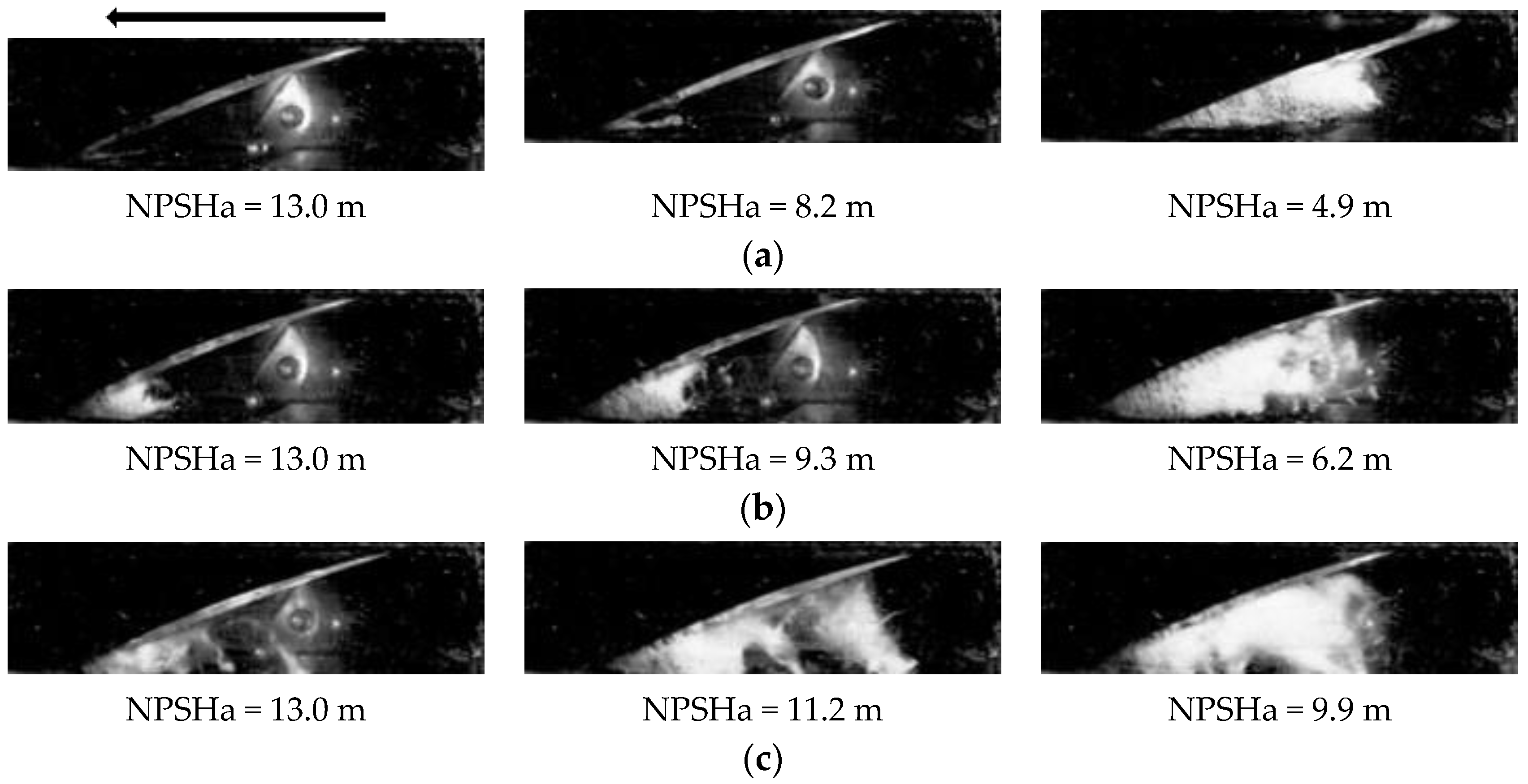
The cavitation phenomenon of tip clearance in the bi-directional axial flow pump is obviously different from that in the conventional axial flow pump. In reverse rotation, cavitation phenomenon exists on both the suction surface and pressure surface under a larger flow condition, which is related to the special shape of S-shaped hydrofoil. At a lower flow rate, the interaction between tip clearance leakage flow and cavitation results in a complex shedding phenomenon.
(3)
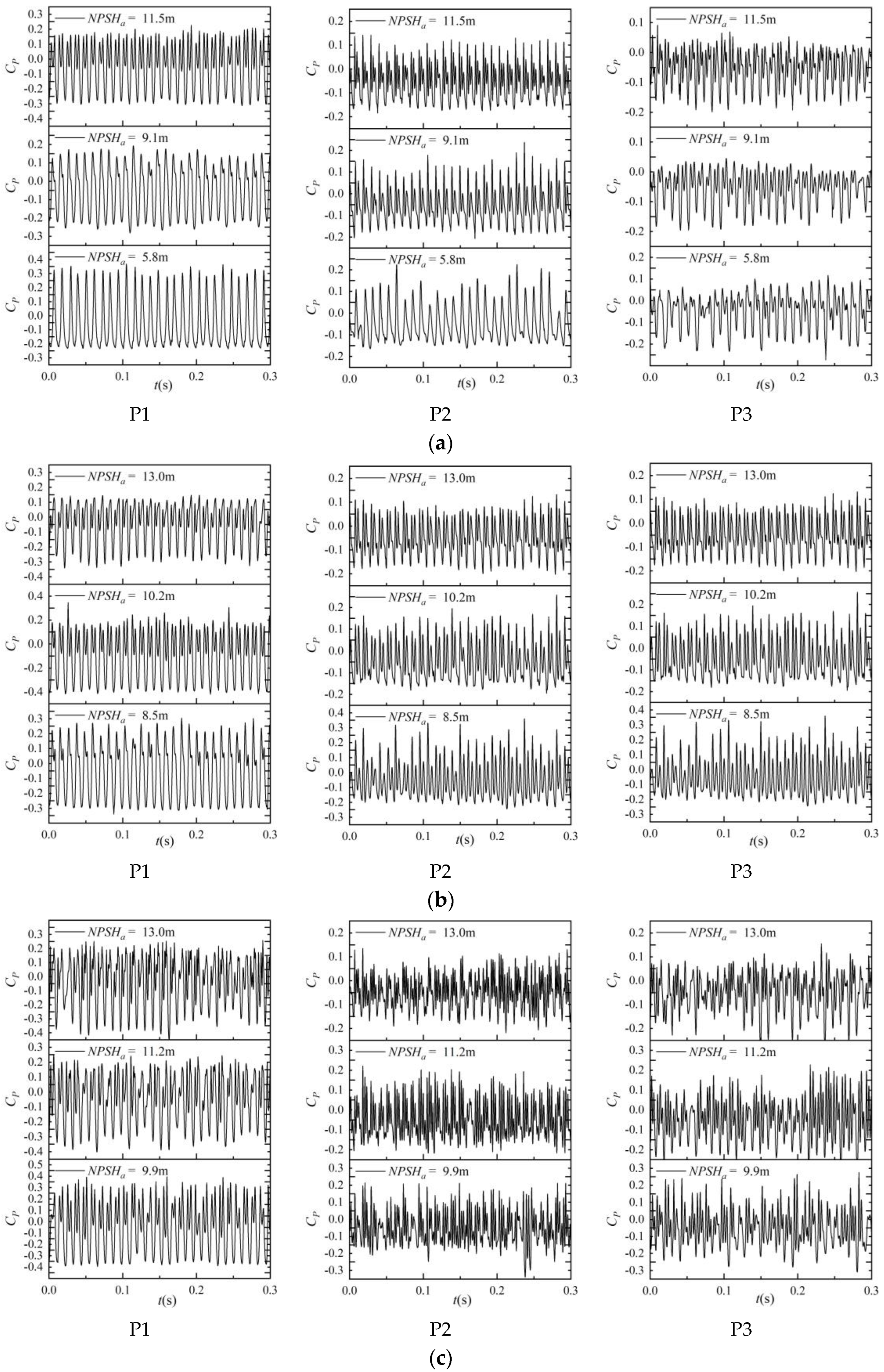
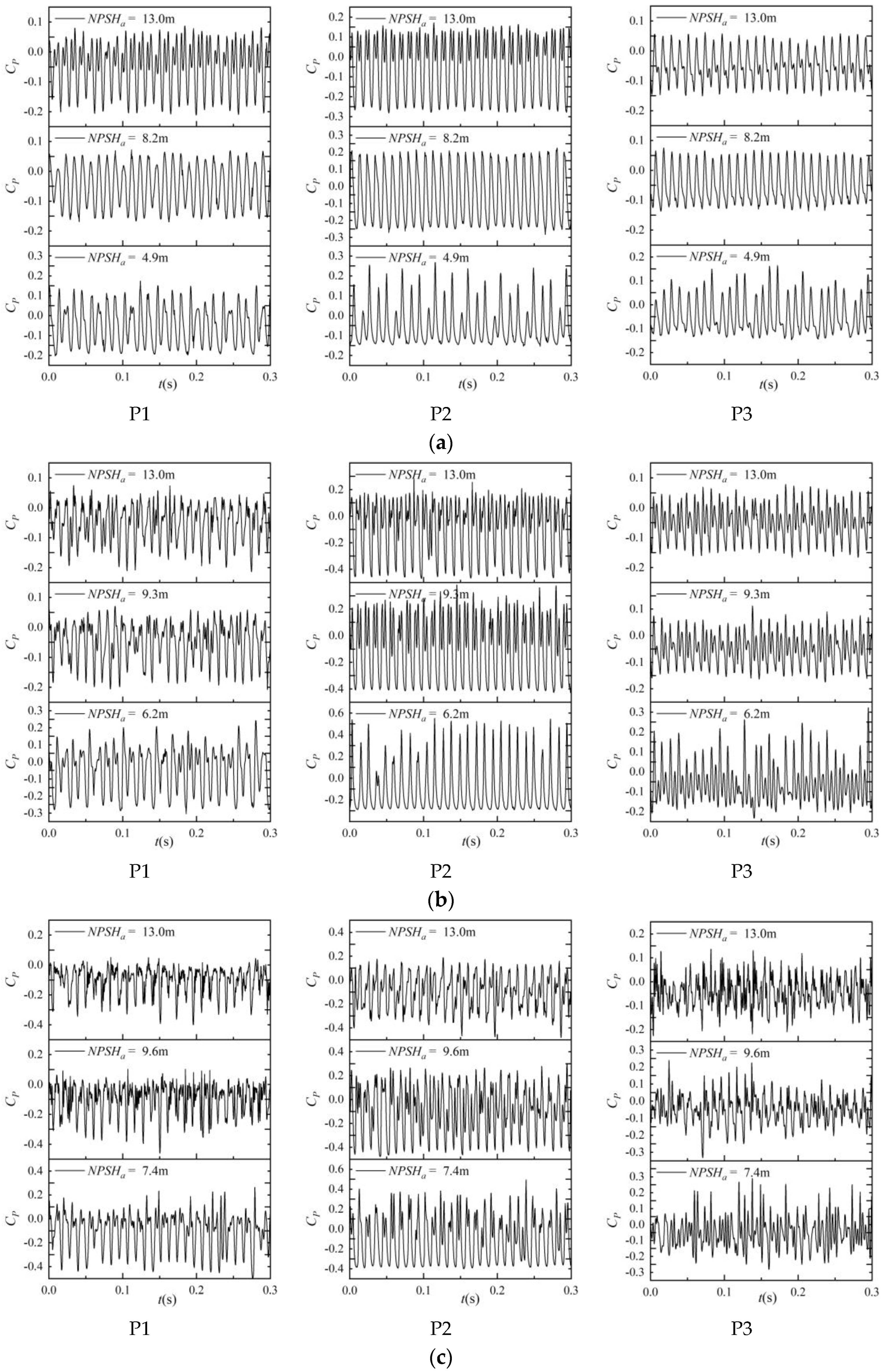
The degree of cavitation development will affect the pressure pulsation. The increase of cavity volume will not only make the pressure pulsation data develop from a smooth and stable signal to a complex multi-peak, but also restrain the complexity of pressure pulsation. The influence of cavitation on pressure pulsation needs to be combined with the flow condition and location.
(4)
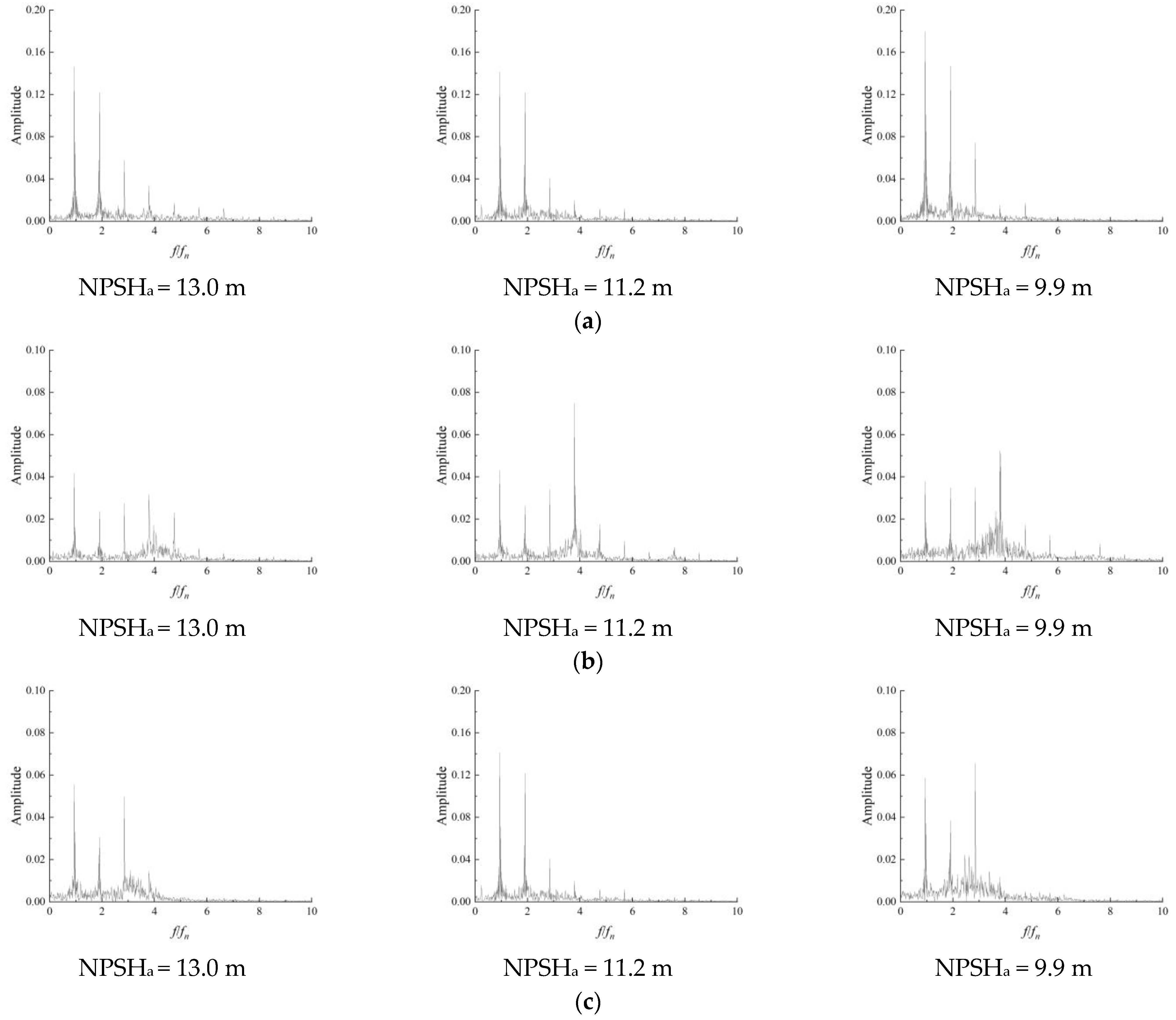
Under critical cavitation conditions and severe cavitation conditions, the pressure pulsation in the middle position of the impeller is relatively stable and the main frequency remains at the rotational frequency of the impeller during forward operation. However, in reverse rotation, there are more harmonic components in the frequency domain diagram of pressure, indicating that the front of the guide vane will affect the pressure pulsation of the clearance of the impeller.
(5)
With the decrease of inlet flow rate, the main frequency at the inlet of the impeller is still the rotation frequency, but the amplitude of other frequencies increases significantly, and the main frequency is mainly concentrated in the lower frequency. It shows that the periodic cloud cavitation shedding is the main factor affecting the pressure pulsation in the impeller.
In future work, the details of the cavitation flow at the tip clearance cavitation flow caused by special shapes of hydrofoil will be investigated in combination with numerical simulation.

Author Contributions

Labs and methodology, F.T.; writing and visualization, H.L.; funding L.S., validation L.D., J.S. and J.L.; All authors agreed to publish this paper. All authors have read and agreed to the published version of the manuscript.

Funding

This research was funded by National Natural Science Foundation of China; the funder: Lijian Shi; the funding number: 52209116.

Institutional Review Board Statement

Not applicable.

Informed Consent Statement

Not applicable.

Data Availability Statement

The experimental data used to support the findings of this study are included within the article.

Conflicts of Interest

The authors declare no conflict of interest.

References

  1. Luo, X.; Ji, B.; Tsujimoto, Y. A review of cavitation in hydraulic machinery. J. Hydrodyn. 2016, 28, 335–358. [Google Scholar] [CrossRef]
  2. Fu, S.; Zheng, Y.; Kan, K.; Chen, H.; Han, X.; Liang, X.; Liu, H.; Tian, X. Numerical simulation and experimental study of transient characteristics in an axial flow pump during start-up. Renew. Energy 2020, 146, 1879–1887. [Google Scholar] [CrossRef]
  3. Furukawa, A.; Shigemitsu, T.; Watanabe, S. Performance test and flow measurement of contra-rotating axial flow pump. J. Therm. Sci. 2007, 16, 7–13. [Google Scholar] [CrossRef]
  4. Chatterjee, D. Computational analysis of flow over a cascade of S-shaped hydrofoil of fully reversible pump-turbine used in extracting tidal energy. Renew. Energy 2015, 77, 240–249. [Google Scholar]
  5. Liu, H.; Tang, F.; Yan, S.; Li, D. Experimental and Numerical Studies of Cloud Cavitation Behavior around a Reversible S-Shaped Hydrofoil. J. Mar. Sci. Eng. 2022, 10, 386. [Google Scholar] [CrossRef]
  6. Kumar TM, P.; Chatterjee, D. Numerical study of turbulent flow over an S-shaped hydrofoil. Proceedings of the Institution of Mechanical Engineers, Part C. J. Mech. Eng. Sci. 2008, 222, 1717–1734. [Google Scholar] [CrossRef]
  7. Franc, J.P.; Michel, J.M. Fundamentals of Cavitation; Springer Science & Business Media: Berlin/Heidelberg, Germany, 2006. [Google Scholar]
  8. Brennen, C.E. Cavitation and Bubble Dynamics; Cambridge University Press: Cambridge, UK, 2014. [Google Scholar]
  9. Young, F.R. Cavitation; World Scientific: Singapore, 1999. [Google Scholar]
  10. Dular, M.; Bachert, B.; Stoffel, B.; Širok, B. Relationship between cavitation structures and cavitation damage. Wear 2004, 257, 1176–1184. [Google Scholar] [CrossRef]
  11. Arndt, R.E.A. Cavitation in fluid machinery and hydraulic structures. Annu. Rev. Fluid Mech. 1981, 13, 273–326. [Google Scholar] [CrossRef]
  12. Wu, H.; Miorini, R.L.; Katz, J. Measurements of the tip leakage vortex structures and turbulence in the meridional plane of an axial water-jet pump. Exp. Fluids 2011, 50, 989–1003. [Google Scholar] [CrossRef]
  13. Zhang, D.; Shi, L.; Shi, W.; Zhao, R.; Wang, H.; van Esch BP, M.B. Numerical analysis of unsteady tip leakage vortex cavitation cloud and unstable suction-side-perpendicular cavitating vortices in an axial flow pump. Int. J. Multiph. Flow 2015, 77, 244–259. [Google Scholar] [CrossRef]
  14. Zhang, D.; Shi, W.; Van Esch BP, M.B.; Shi, L.; Dubuisson, M. Numerical and experimental investigation of tip leakage vortex trajectory and dynamics in an axial flow pump. Comput. Fluids 2015, 112, 61–71. [Google Scholar] [CrossRef]
  15. Zhang, D.; Shi, W.; Pan, D.; Dubuisson, M. Numerical and experimental investigation of tip leakage vortex cavitation patterns and mechanisms in an axial flow pump. J. Fluids Eng. 2015, 137, 121103. [Google Scholar] [CrossRef]
  16. Hao, Y.; Tan, L. Symmetrical and unsymmetrical tip clearances on cavitation performance and radial force of a mixed flow pump as turbine at pump mode. Renew. Energy 2018, 127, 368–376. [Google Scholar] [CrossRef]
  17. Li, D.; Wang, H.; Qin, Y.; Han, L.; Wei, X.; Qin, D. Entropy production analysis of hysteresis characteristic of a pump-turbine model. Energy Convers. Manag. 2017, 149, 175–191. [Google Scholar] [CrossRef]
  18. Shen, X.; Zhang, D.S.; Xu, B.; Jin, Y.X.; Shi, W.; van Esch BP, M.B. Experimental investigation of the transient patterns and pressure evolution of tip leakage vortex and induced-vortices cavitation in an axial flow pump. J. Fluids Eng. 2020, 142, 101206. [Google Scholar]
  19. Shen, X.; Zhang, D.S.; Xu, B.; Shi, W.; van Esch BP, M.B. Experimental and numerical investigation on the effect of tip leakage vortex induced cavitating flow on pressure fluctuation in an axial flow pump. Renew. Energy 2021, 163, 1195–1209. [Google Scholar]
  20. Shi, G.; Wang, S.; Xiao, Y.; Liu, Z.; Li, H.; Liu, X. Effect of cavitation on energy conversion characteristics of a multiphase pump. Renew. Energy 2021, 177, 1308–1320. [Google Scholar] [CrossRef]
  21. Wang, L.; Tang, F.; Chen, Y.; Liu, H. Evolution Characteristics of Suction-Side-Perpendicular Cavitating Vortex in Axial Flow Pump under Low Flow Condition. J. Mar. Sci. Eng. 2021, 9, 1058. [Google Scholar] [CrossRef]
  22. Yan, X.; Huang, Y.; He, K.; Li, J.; Feng, Z. Numerical investigations into the effect of squealer–winglet blade tip modifications on aerodynamic and heat transfer performance. Int. J. Heat Mass Transf. 2016, 103, 242–253. [Google Scholar] [CrossRef]
  23. De Maesschalck, C.; Lavagnoli, S.; Paniagua, G. Blade tip carving effects on the aerothermal performance of a transonic turbine. J. Turbomach. 2015, 137, 021005. [Google Scholar] [CrossRef]
  24. Roussopoulos, K.; Monkewitz, P.A. Measurements of tip vortex characteristics and the effect of an anti-cavitation lip on a model Kaplan turbine blade. Flow Turbul. Combust. 2000, 64, 119–144. [Google Scholar] [CrossRef]
  25. Lei, T.; Zhifeng, X.; Yabin, L.; Hao, Y.; Xu, Y. Influence of T-shape tip clearance on performance of a mixed-flow pump. Proceedings of the Institution of Mechanical Engineers, Part A. J. Power Energy 2018, 232, 386–396. [Google Scholar] [CrossRef]
  26. Liu, Y.; Tan, L. Influence of C groove on suppressing vortex and cavitation for a NACA0009 hydrofoil with tip clearance in tidal energy. Renew. Energy 2020, 148, 907–922. [Google Scholar] [CrossRef]
  27. Nazir, U.; Saleem, S.; Al-Zubaidi, A.; Shahzadi, I.; Feroz, N. Thermal and mass species transporta-tion in tri-hybridized Sisko martial with heat source over vertical heated cylinder. Int. Commun. Heat Mass Transf. 2022, 134, 106003. [Google Scholar] [CrossRef]
  28. Nazir, U.; Sohail, M.; Hafeez, M.B.; Krawczuk, M. Significant production of thermal ener-gy in partially ionized hyperbolic tangent material based on ternary hybrid nano-materials. Energies 2021, 14, 6911. [Google Scholar] [CrossRef]
  29. Sohail, M.; El-Zahar, E.R.; Mousa AA, A.; Nazir, U.; Althobaiti, S.; Althobaiti, A.; Shah, N.A.; Chung, J.D. Finite element analysis for ter-nary hybrid nanoparticles on thermal enhancement in pseudo-plastic liquid through porous stretching sheet. Sci. Rep. 2022, 12, 1–13. [Google Scholar]
  30. Sohail, M.; Nazir, U.; El-Zahar, E.R.; Alrabaiah, H.; Kumam, P.; Mousa, A.A.; Sitthithakerngkiet, K.; Park, C. A study of triple-mass diffusion species and energy transfer in Carreau–Yasuda material influenced by activation energy and heat source. Sci. Rep. 2022, 12, 1–17. [Google Scholar] [CrossRef]
  31. Nazir, U.; Sohail, M.; Singh, A.; Muhsen, S.; Galal, A.M.; El Din, E.S.M.T.; Hussain, S.M. Finite element analysis for thermal enhancement in power law hybrid nanofluid. Front. Phys. 2022, 10, 996174. [Google Scholar] [CrossRef]
  32. Song, X.; Chao, L.; Wang, Z. Prediction on the pressure pulsation induced by the free surface vortex based on experimental investigation and Biot-Savart Law. Ocean. Eng. 2022, 250, 110934. [Google Scholar] [CrossRef]
  33. Song, X.; Luo, Y.; Wang, Z. Numerical prediction of the influence of free surface vortex air-entrainment on pump unit performance. Ocean. Eng. 2022, 256, 111503. [Google Scholar] [CrossRef]
  34. Song, X.; Liu, C. Experimental investigation of floor-attached vortex effects on the pressure pulsation at the bottom of the axial flow pump sump. Renew. Energy 2020, 145, 2327–2336. [Google Scholar] [CrossRef]
  35. Liu, H.; Lin, P.; Tang, F.; Chen, Y.; Zhang, W.; Yan, S. Experimental Study on the Relationship Between Cavitation and Lift Fluctuations of S-Shaped Hydrofoil. Front. Energy Res. 2021, 902. [Google Scholar] [CrossRef]
Figure 1. Impeller, Guide vane and Pump section. (a) Impeller, (b) Guide vane, (c) Pump section.
Jmse 11 00268 g001
Figure 2. Position of high speed photography and pressure pulsation sensor. (a) High speed photography, (b) Pressure pulsation sensors.
Jmse 11 00268 g002
Figure 3. Bi-directional pump performance when operating in different directions. (a) forward operation, (b) reverse operation.
Jmse 11 00268 g003
Figure 4. Cavitation image under different flow rate and different cavitation number (Arrows indicate the direction of rotation of the impeller). (a) Q = 1.13 Qd. (b) Q = 1.0 Qd. (c) Q = 0.85 Qd.
Jmse 11 00268 g004
Figure 5. Cavitation image under different flow rates and different cavitation numbers (Arrows indicate the direction of rotation of the impeller). (a) Q = 1.13 Qd. (b) Q = 1.0 Qd. (c) Q = 0.85 Qd.
Jmse 11 00268 g005
Figure 6. Evolution of pressure pulsation under different flow rate and cavitation number. (forward rotation). (a) Q = 1.13 Qd. (b) Q = 1.0 Qd. (c) Q = 0.85 Qd.
Jmse 11 00268 g006
Figure 7. Evolution of pressure pulsation under different flow rates and cavitation numbers (forward rotation). (a) Q = 1.13 Qd. (b) Q = 1.0 Qd. (c) Q = 0.85 Qd.
Jmse 11 00268 g007
Figure 8. Frequency domain diagram of pressure pulsation under different cavitation number conditions (Q = 0.85 Qd). (a) P1. (b) P2. (c) P3.
Jmse 11 00268 g008
Figure 9. Frequency domain diagram of pressure pulsation under different cavitation number conditions (Q = 0.85 Qd). (a) P3, (b) P2, (c) P1.
Jmse 11 00268 g009
Table 1. The parameters of bi-directional axial flow pump.
NameValue
Impeller diameter0.30 m
Tip clearance0.5 mm
Rotation speed±1450 r/min
Inlet diameter0.350 m
Elbow angle60°
Outlet diameter0.350 m
Flow rate0.10~0.440 m3/s
Table 2. Instrument parameters for model tests.
Measured ItemNameRangeUncertainty
HeadDifferential pressure transmitter0~200 kPa±0.1%
Flow rateElectromagnetic flowmeter0~500 L/s±0.2%
TorqueSpeed and torque sensor0~500 N·m±0.15%
NPSHaAbsolute pressure transmitter0~130 kPa±0.025%
Cavity imageHigh-speed camera0~7400 f/s
Pressure transmitterPressure pulsation sensor0~200 kPa±0.1%
Disclaimer/Publisher’s Note: The statements, opinions and data contained in all publications are solely those of the individual author(s) and contributor(s) and not of MDPI and/or the editor(s). MDPI and/or the editor(s) disclaim responsibility for any injury to people or property resulting from any ideas, methods, instructions or products referred to in the content.

