
Design and Implementation of a Multi-Function Hydrophone for Underwater Acoustic Application

Abstract
:1. Introduction
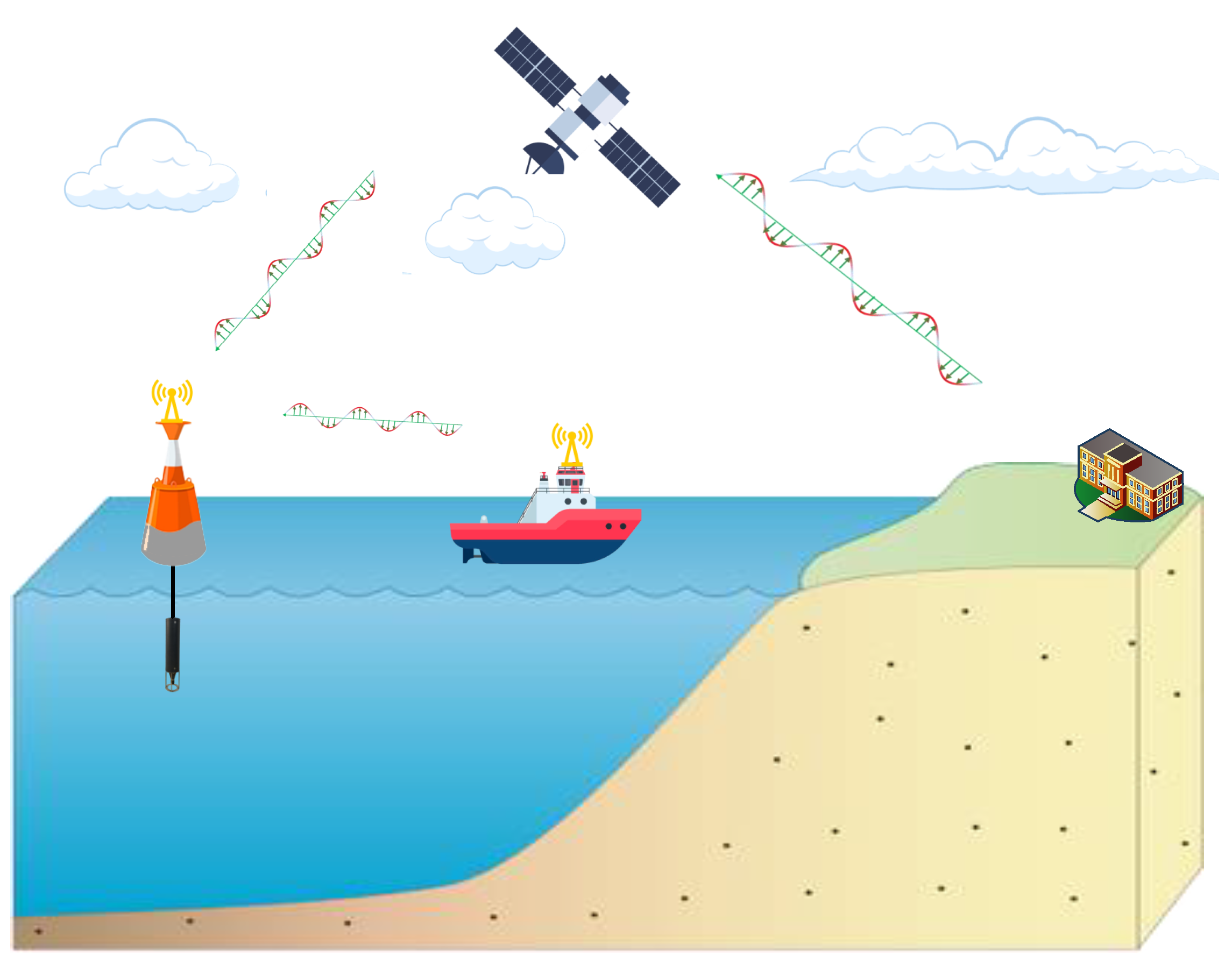
2. System Overview
2.1. Hardware Design
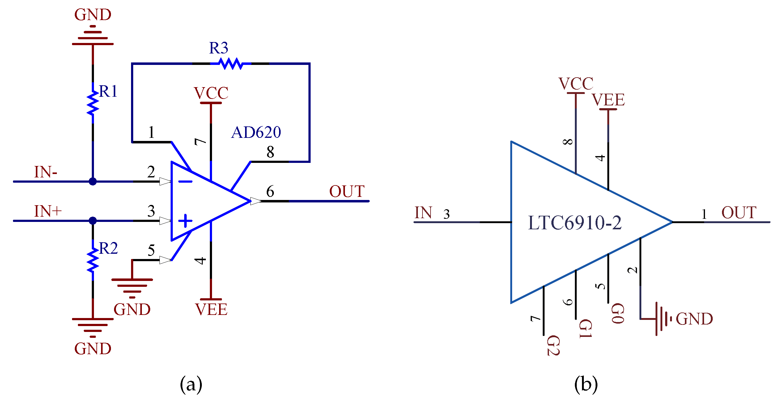
2.1.1. The Pre-Amplifier
2.1.2. The Analog-to-Digital Converter
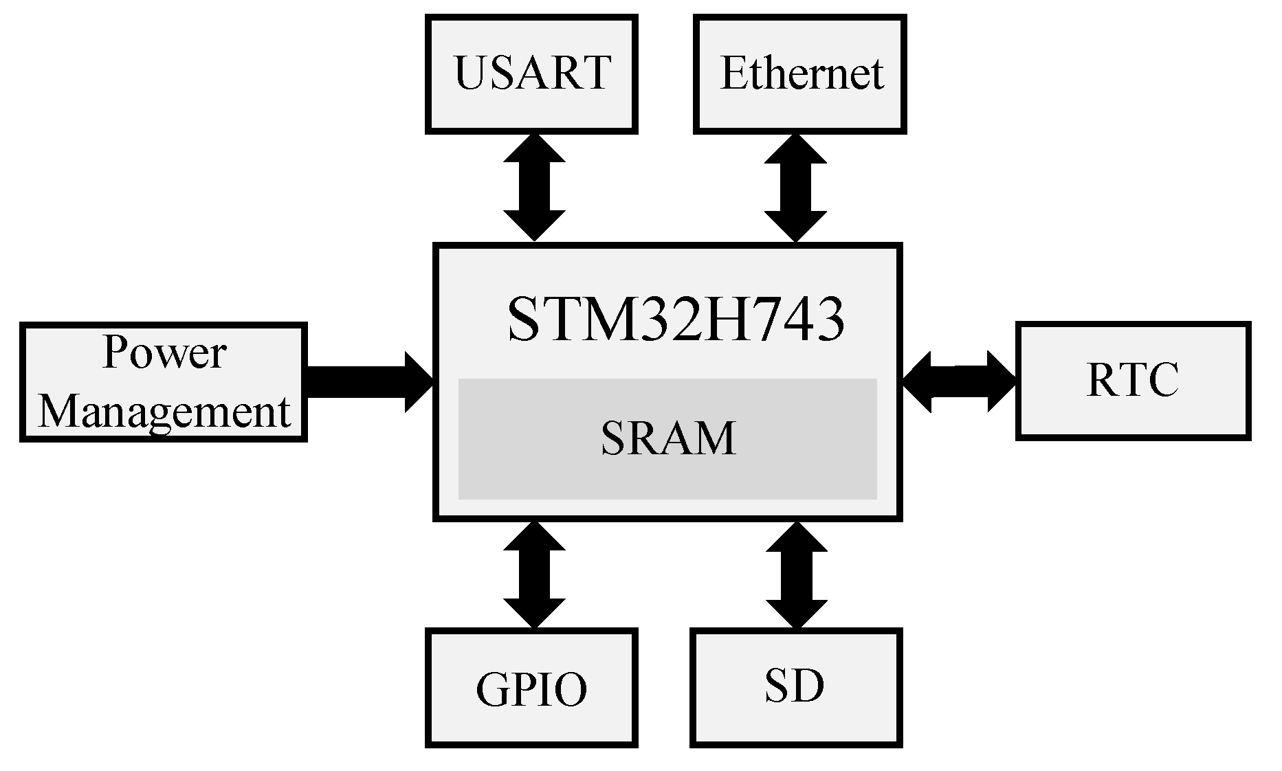
2.1.3. The Micro-Controller and Peripheral
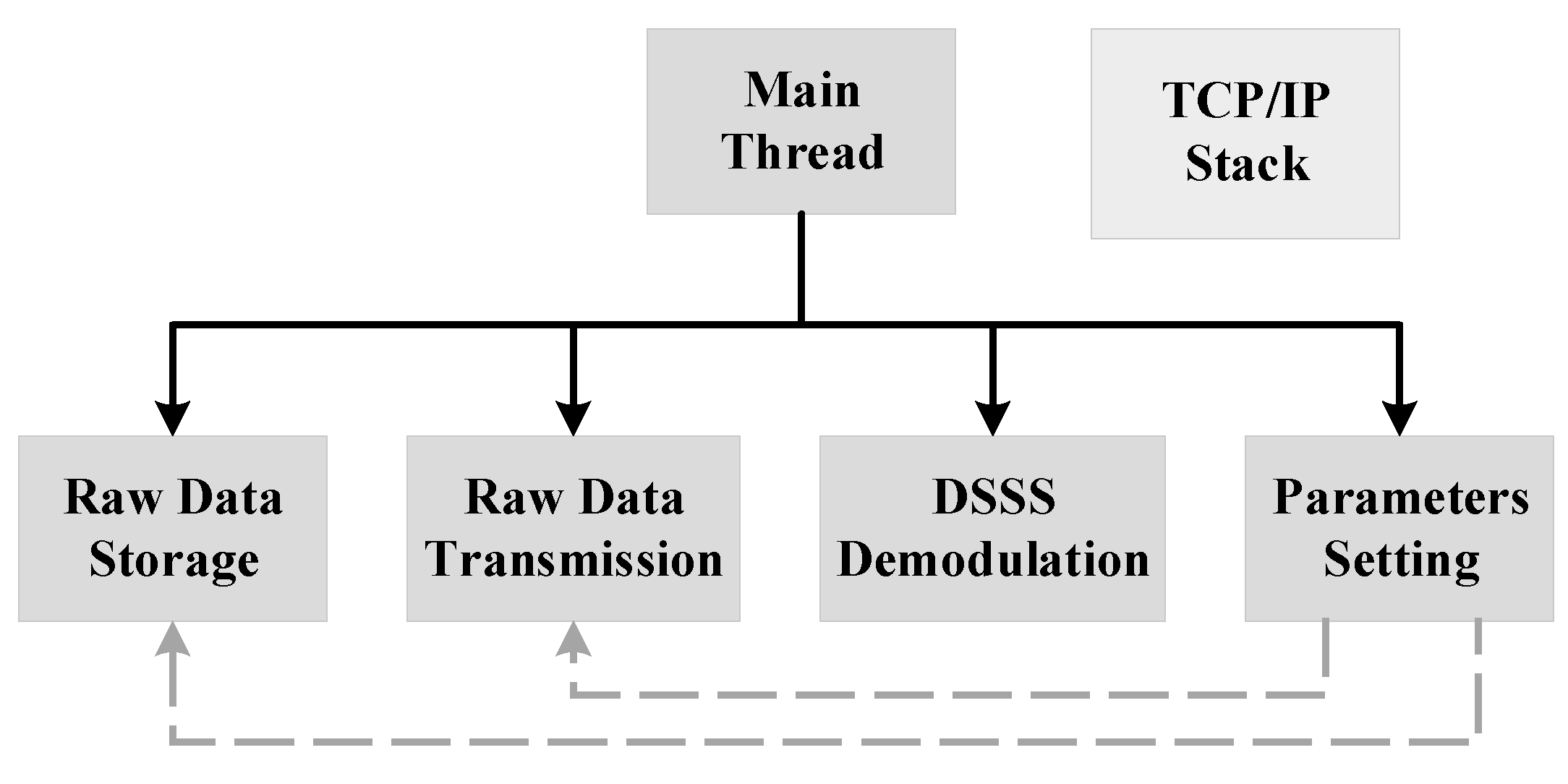
2.2. Software Design
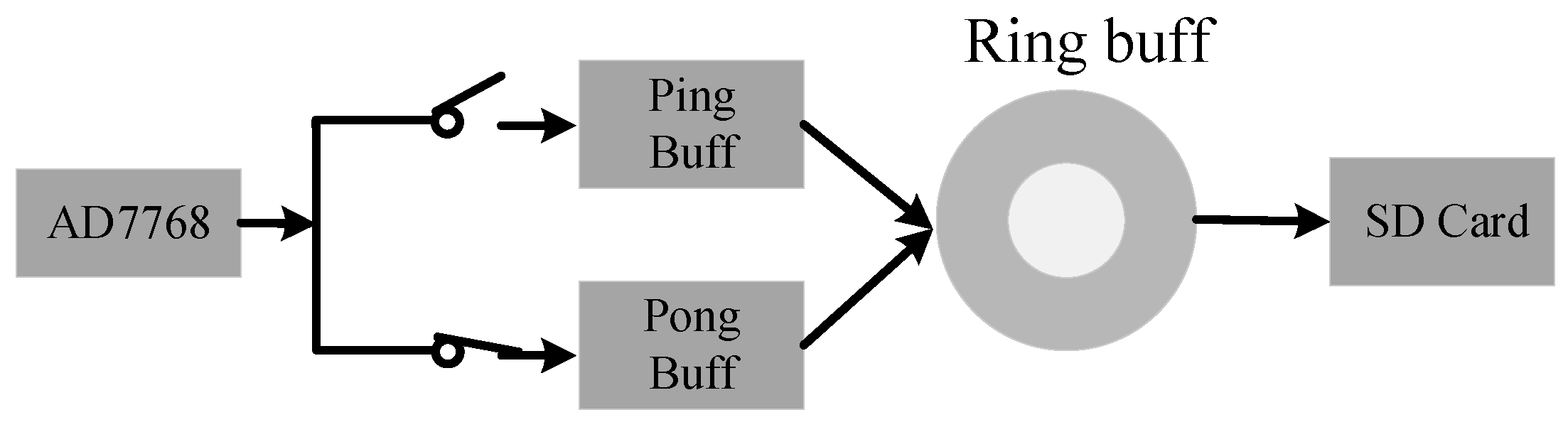
2.2.1. Local Data Preservation
2.2.2. Data Uploading
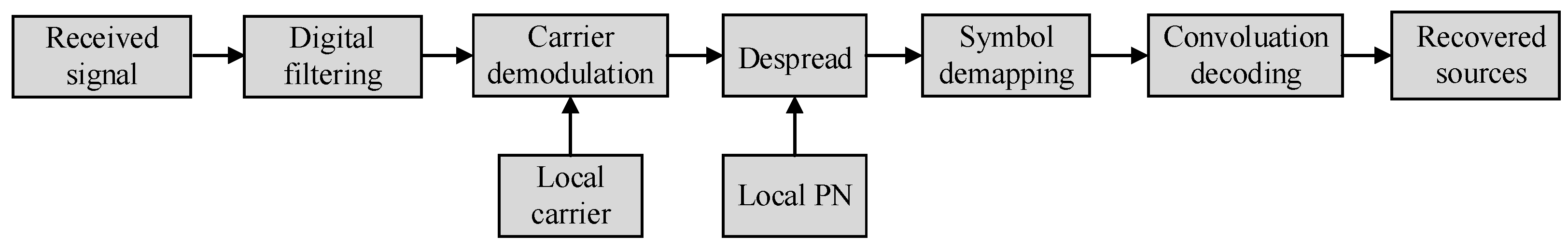
2.2.3. Spread Spectrum Communication Technology
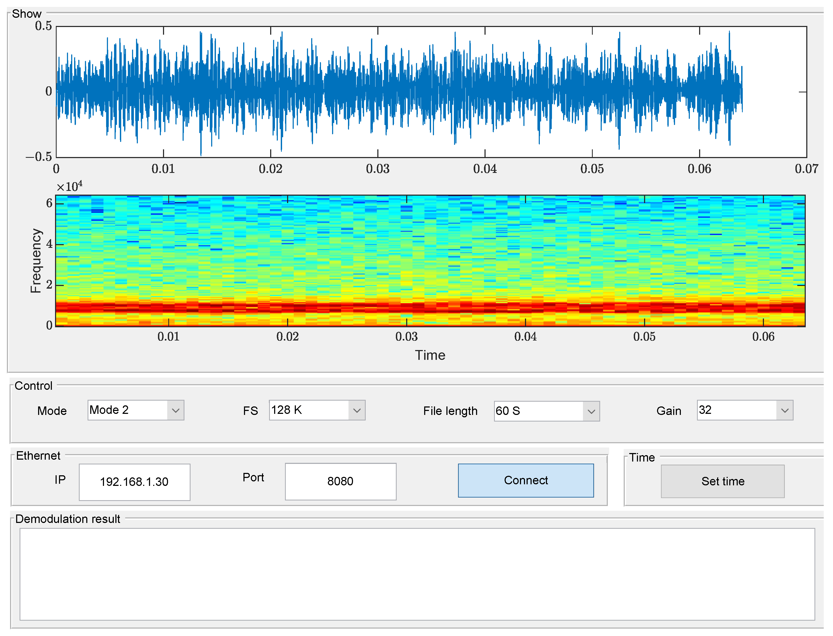
2.2.4. Parameters Setting
3. Results and Analysis
3.1. Experimental Results in Mode 1
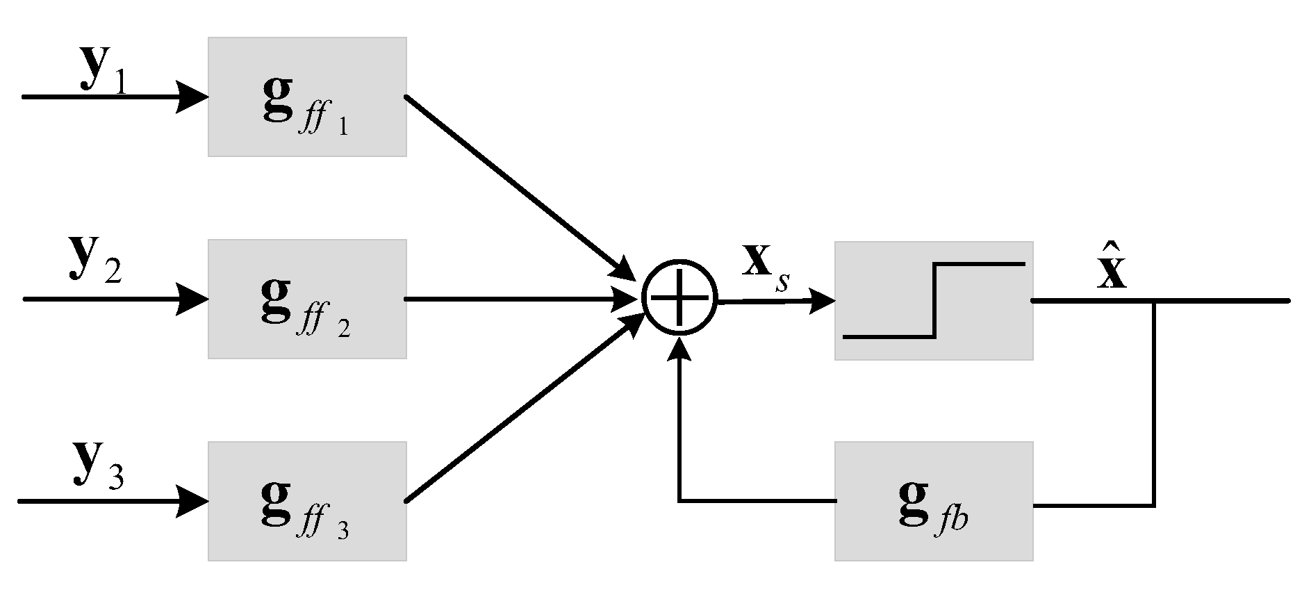
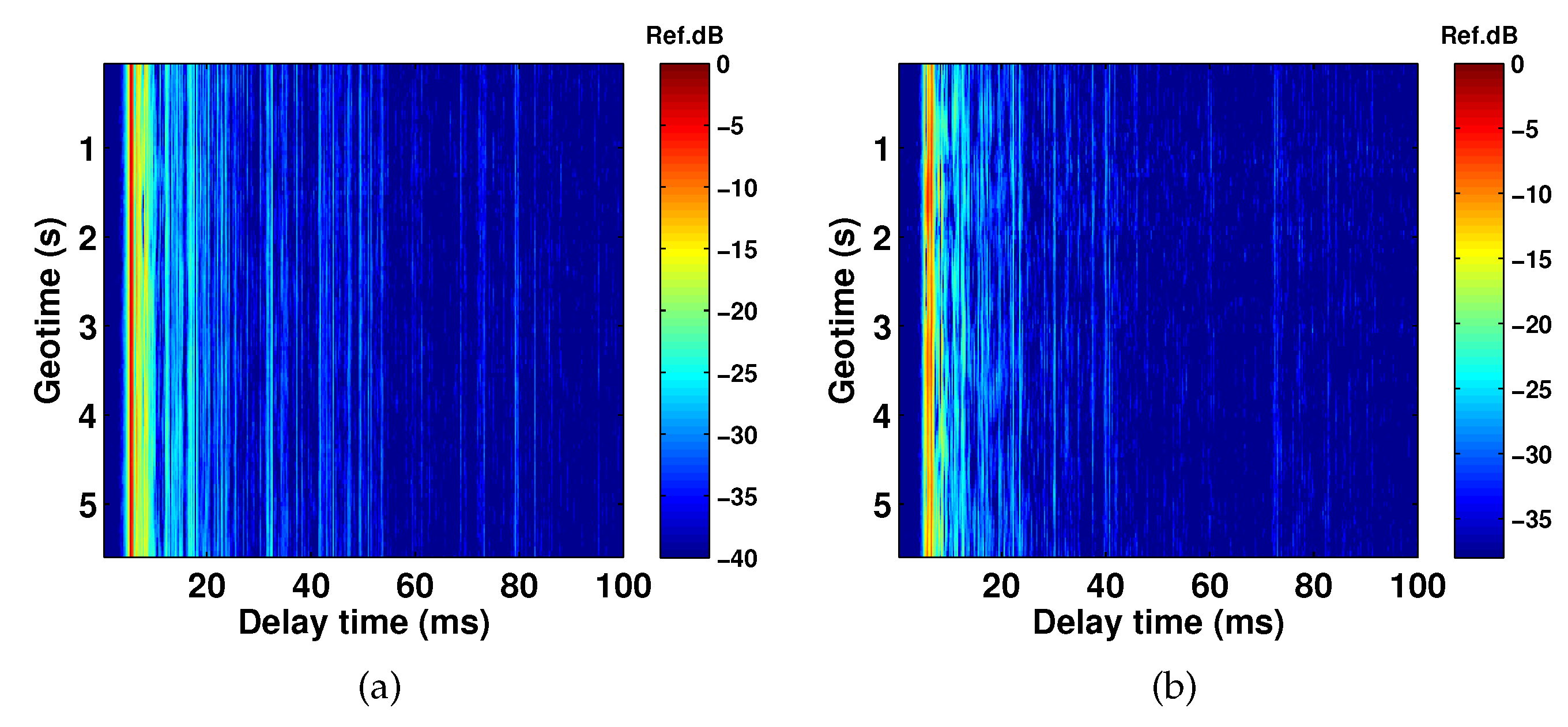
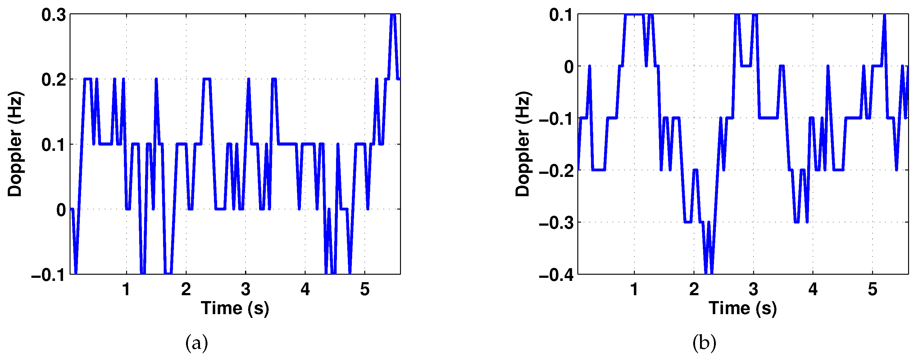
3.2. Experimental Results in Mode 2
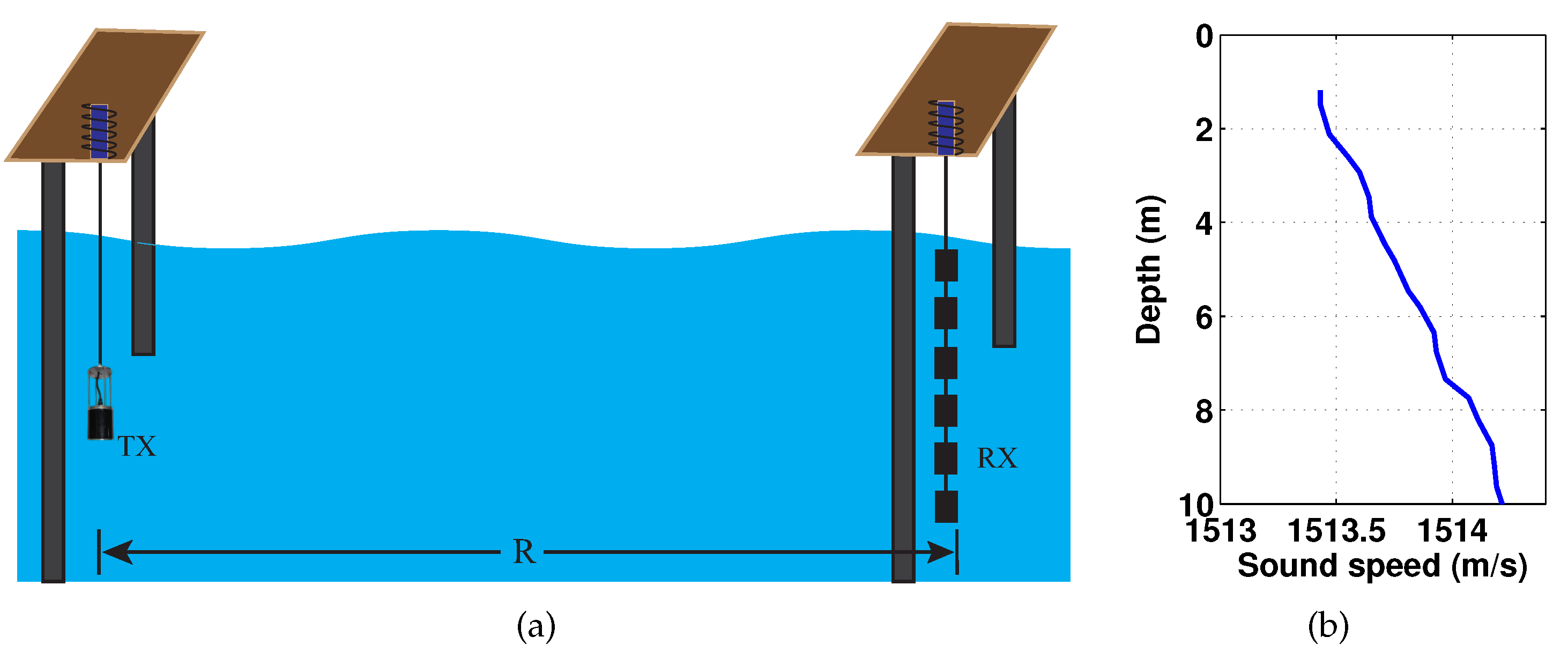
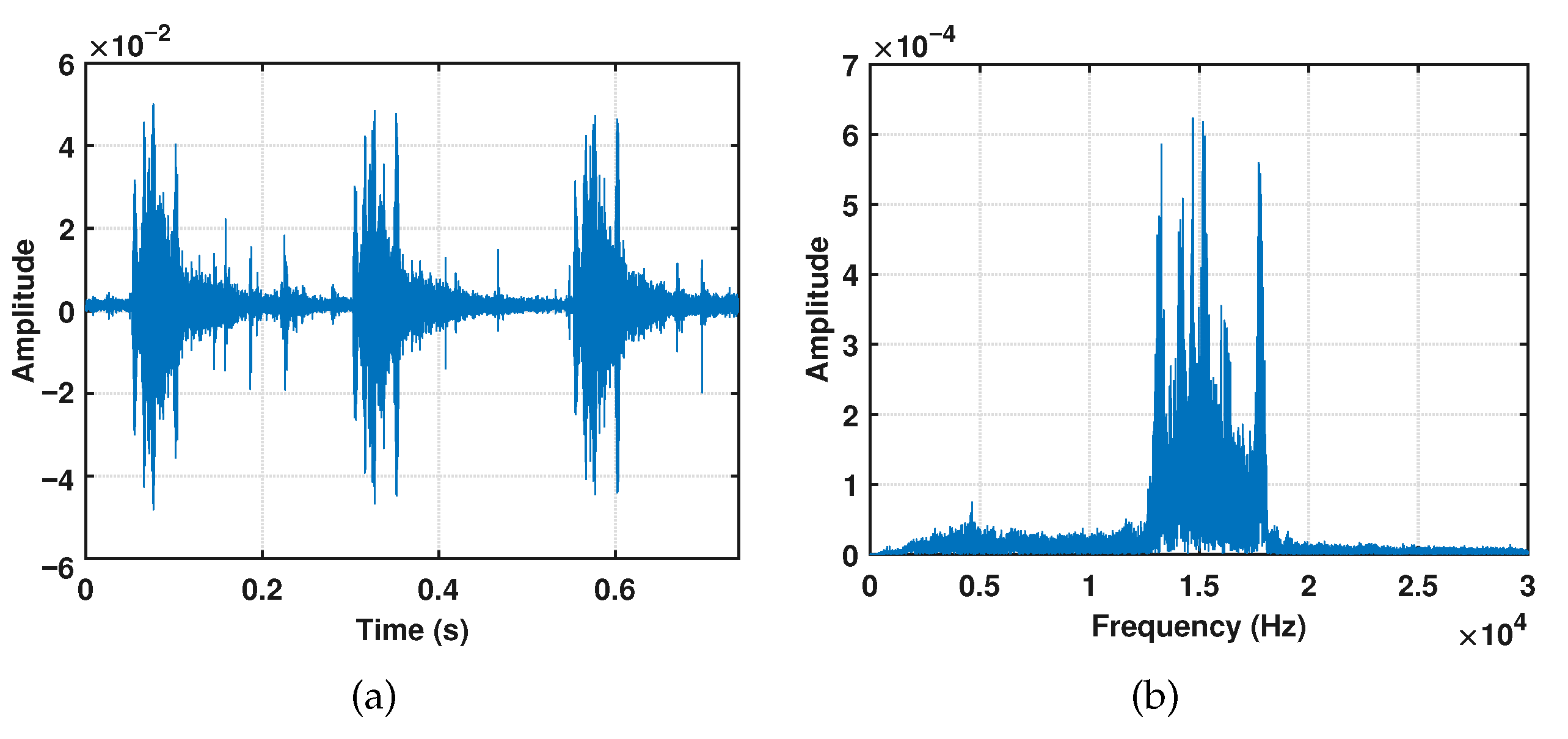
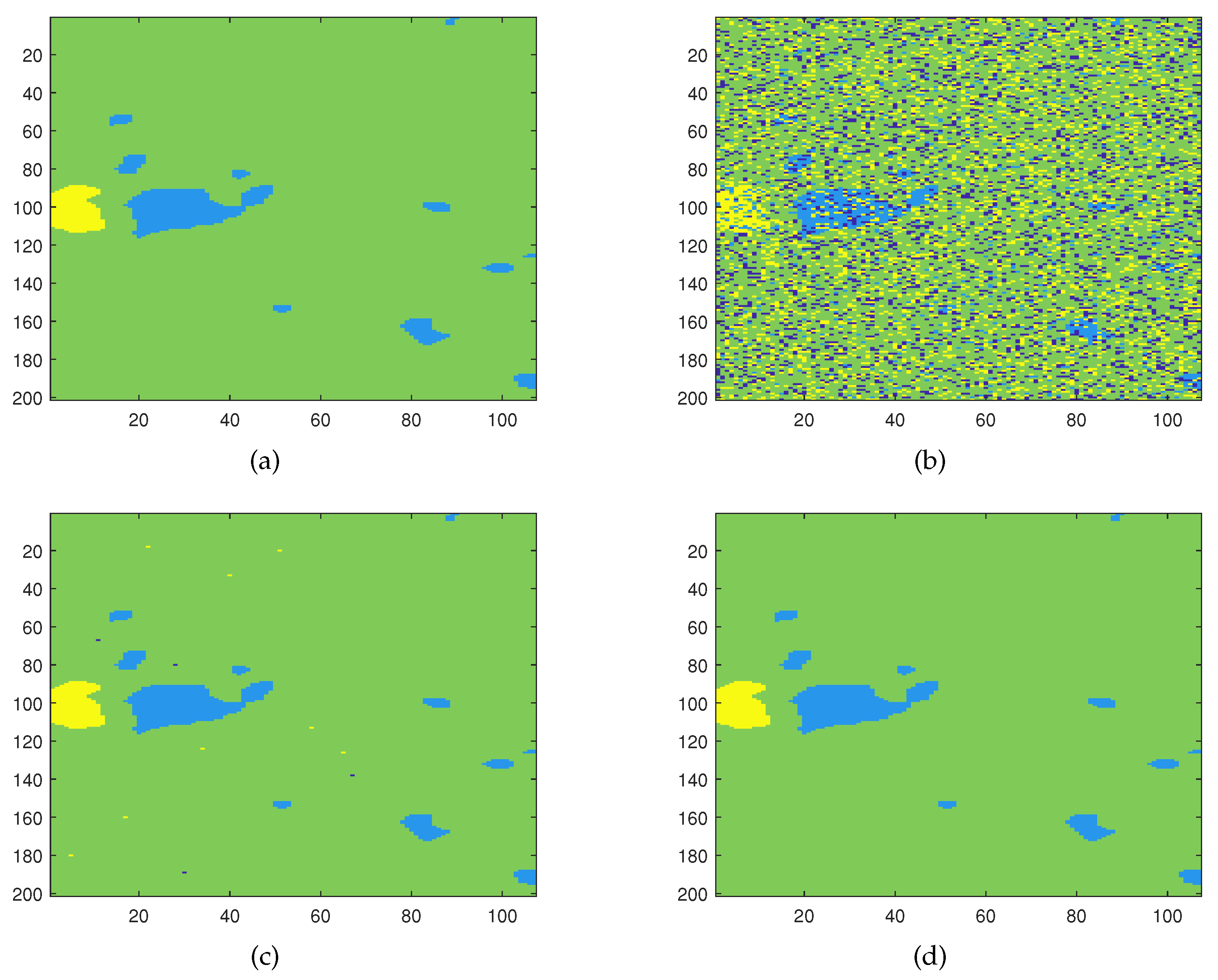
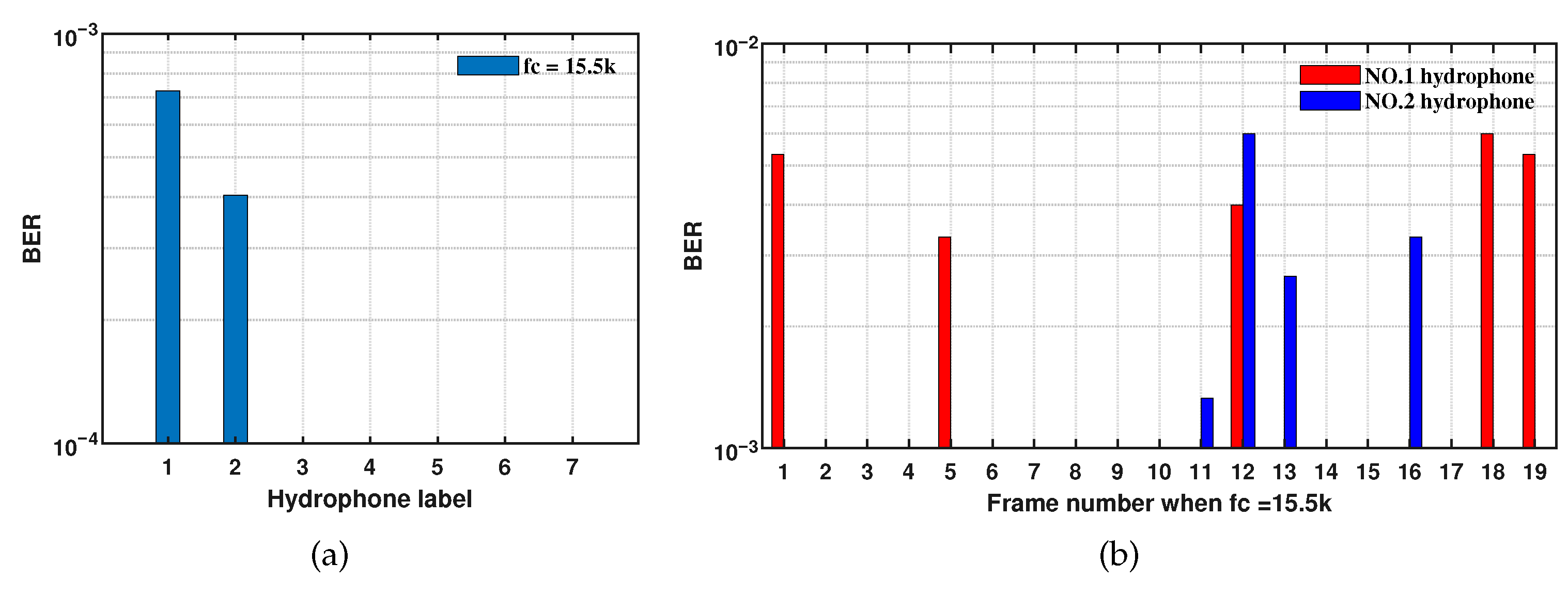
3.3. Experimental Results in Mode 3
4. Conclusions
Author Contributions
Funding
Institutional Review Board Statement
Informed Consent Statement
Data Availability Statement
Conflicts of Interest
Abbreviations
| ADC | Analog-to-Digital Converter |
| ASK | Amplitude Shift Keying |
| AUV | Autonomous Underwater Vehicle |
| BER | Bit Error Rate |
| CE-DFE | Channel Estimation based Decision Feedback Equalizer |
| CPU | Central Processing Unit |
| DA-DFE | Direct Adaptive Decision Feedback Equalizer |
| DMIPS | Dhrystone Million Instructions Per Second |
| DSP | Digital Signal Processor |
| DSSS | Direct Sequence Spread Spectrum |
| DMA | Direct Memory Access |
| FPU | Floating Point Unit |
| FTP | File Transfer Protocol |
| GPIO | General Purpose Input Output |
| GUI | Graphical User Interface |
| kSPS | Kilo-Symbols Per Second |
| LDPC | Low-density Parity-check |
| LFM | Linear Frequency Modulation |
| MCASP | Multichannel Audio Serial Port |
| MCU | Micro-controller Unit |
| OFDM | Orthogonal Frequency Division Multiplexing |
| OOK | On-off Keying |
| OSDM | Orthogonal Signal Division Multiplexing |
| PN | Pseudo Noise |
| QPSK | Quadrature Phase Shift Keying |
| RTC | Real-time Clock |
| SD | Secure Digital |
| SNR | Signal to Noise Ratio |
| SPI | Serial Peripheral Interface |
| SSP | Sound Speed Profile |
| ST | STMicroelectronics |
| TCP/IP | Transmission Control Protocol/Internet Protocol |
| UDP | User Datagram Protocol |
| USART | Universal Synchronous/Asynchronous Receiver/Transmitter |
| UUV | Unmanned Underwater Vehicle |
| WAV | Waveform |
| 1 | This picture is from Acoustic and Navigation Laboratory (ANL) in Haifa University, Israel. |
References
- Toma, D.M.; Masmitja, I.; del Río, J.; Martinez, E.; Artero-Delgado, C.; Casale, A.; Figoli, A.; Pinzani, D.; Cervantes, P.; Ruiz, P.; et al. Smart embedded passive acoustic devices for real-time hydroacoustic surveys. Measurement 2018, 125, 592–605. [Google Scholar] [CrossRef]
- Miksis-Olds, J.L.; Nichols, S.M. Is low frequency ocean sound increasing globally? J. Acoust. Soc. Am. 2016, 139, 501–511. [Google Scholar] [CrossRef] [PubMed]
- Kolar, H.R.; McKeown, E.P.; Purcell, M.E.; Gaughan, P.J.; Westbrook, A.G.; Barry, M.G.; Akhriev, A.M.; Hayes, J.P.; Castelfranco, A.; Nolan, G.; et al. The design and deployment of a real-time wide spectrum acoustic monitoring system for the ocean energy industry. In Proceedings of the 2013 MTS/IEEE OCEANS-Bergen, Bergen, Norway, 10–14 June 2013. [Google Scholar]
- Hayes, J.P.; Kolar, H.R.; Akhriev, A.; Barry, M.G.; Purcell, M.E.; McKeown, E.P. A real-time stream storage and analysis platform for underwater acoustic monitoring. IBM J. Res. Dev. 2013, 57, 15:1–15:10. [Google Scholar] [CrossRef]
- Liu, L.; Xiao, L.; Lan, S.; Liu, T.-T.; Song, G. Using petrel II glider to analyze underwater noise spectrogram in the south China sea. Acoust. Aust. 2018, 46, 151–158. [Google Scholar] [CrossRef]
- Dassatti, A.; van der Schaar, M.; Guerrini, P.; Zaugg, S.; Houégnigan, L.; Maguer, A.; André, M. On-board underwater glider real-time acoustic environment sensing. In Proceedings of the OCEANS 2011 IEEE—Spain, Santander, Spain, 6–9 June 2011. [Google Scholar]
- Chen, T.; Chan, J.; Gollakota, S. Underwater acoustic ranging between smartphones. arXiv 2022, arXiv:2209.01780. [Google Scholar]
- Jeon, J.-H.; Hwangbo, S.-H.; Peyvandi, H.; Park, S.-J. Design and implementation of a bidirectional acoustic micro-modem for underwater communication systems. In Proceedings of the 2012 Oceans, Hampton Roads, VA, USA, 14–19 October 2012. [Google Scholar]
- Younce, J.; Singer, A.; Riedl, T.; Landry, B.; Bean, A.; Arikan, T. Experimental results with HF underwater acoustic modem for high bandwidth applications. In Proceedings of the 2015 49th Asilomar Conference on Signals, Systems and Computers, Pacific Grove, CA, USA, 8–11 November 2015. [Google Scholar]
- Martins, M.S.; Cabral, J.; Lopes, G.; Ribeiro, F. Underwater acoustic modem with streaming video capabilities. In Proceedings of the OCEANS 2015-Genova, Genova, Italy, 18–21 May 2015. [Google Scholar]
- Zhou, Y.; Tong, F. Research and development of a highly reconfigurable OFDM MODEM for shallow water acoustic communication. IEEE Access 2019, 7, 123569–123582. [Google Scholar] [CrossRef]
- Yang, X.; Zhou, Y.; Wang, R.; Tong, F. Research and implementation on a real-time OSDM MODEM for underwater acoustic communications. IEEE Sens. J. 2023, 23, 18434–18448. [Google Scholar] [CrossRef]
- Green, D.; McManus, S. Smart modems—Underwater capabilities beyond communications. In Proceedings of the 2012 Oceans-Yeosu, Yeosu, Korea, 21–24 May 2012. [Google Scholar]
- Caldas-Morgan, M.; Alvarez-Rosario, A.; Rodrigues Padovese, L. An autonomous underwater recorder based on a single board computer. PLoS ONE 2015, 10, e0130297. [Google Scholar] [CrossRef] [PubMed]
- Ocean Sonics Introduction of Iclisten sc2, Canada. Available online: https://oceansonics.com/product-types/iclisten-smart-hydrophones/ (accessed on 21 October 2023).
- Loggerhead Instruments. Snap Recorder, Florida, USA. Available online: https://www.loggerhead.com/snap (accessed on 21 October 2023).
- Cetacean Research Technology. Remote Underwater Digital Acoustic Recorders, USA. Available online: https://www.cetaceanresearch.com/hydrophone-systems/rudar/index.html (accessed on 21 October 2023).
- Ocean Instruments. Soundtrap, New Zealand. Available online: http://www.oceaninstruments.co.nz/shop/ (accessed on 21 October 2023).
- Abyssens. Full Technical Specifications of DORI Recorders, Brittany, France. Available online: https://www.abyssens.fr/underwater-acoustic-recorders-dori/ (accessed on 21 October 2023).
- Analog Devices, Inc. AD620: Low Cost Low Power Instrumentation Amplifier; Rev, H., Ed.; Analog Devices, Inc.: Norwood, MA, USA, 2009. [Google Scholar]
- Analog Devices, Inc. LTC6910: Digitally Controlled Programmable Gain Amplifiers in SOT-23 Data Sheet; Rev, B., Ed.; Analog Devices, Inc.: Norwood, MA, USA, 2017. [Google Scholar]
- STMicroelectronics Product Overview of STM32H743XI. Available online: https://www.st.com/en/microcontrollers-microprocessors/stm32h743xi.html (accessed on 21 October 2023).
- Poisel, R.A. Modern Communications Jamming Principles and Techniques, 2nd ed.; Artech House, Inc.: Norwood, MA, USA, 2011. [Google Scholar]
- Kochanska, I.; Salamon, R.; Schmidt, J.; Schmidt, A. Study of the Performance of DSSS UAC System Depending on the System Bandwidth and the Spreading Sequence. Sensors 2021, 21, 2484–2504. [Google Scholar] [CrossRef] [PubMed]
- Zhou, Y.; Tong, F.; Song, A.; Diamant, R. Exploiting spatial–temporal joint sparsity for underwater acoustic multiple-input–multiple-output communications. IEEE J. Ocean. Eng. 2020, 46, 142–149. [Google Scholar] [CrossRef]
- Preisig, J. Performance analysis of adaptive equalization for coherent acoustic communications in the time-varying ocean environment. J. Acoust. Soc. Am. 2005, 118, 264–278. [Google Scholar] [CrossRef] [PubMed]
- Zhou, Y.; Song, A.; Tong, F.; Kastner, R. Distributed compressed sensing based channel estimation for underwater acoustic multiband transmissions. J. Acoust. Soc. Am. 2018, 143, 3985–3996. [Google Scholar] [CrossRef] [PubMed]


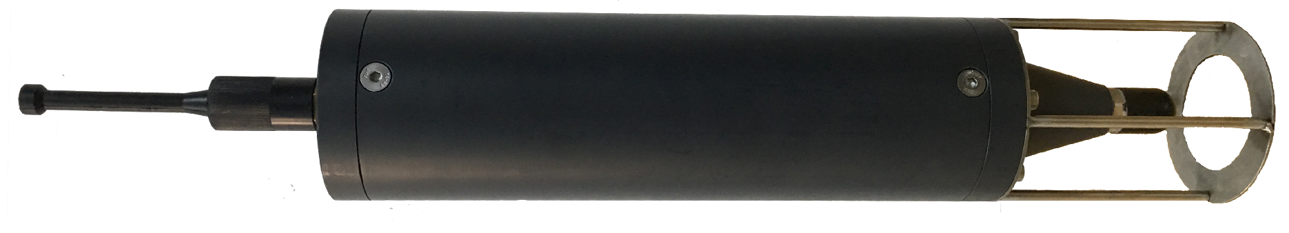
| Parameter | Value | Parameter | Value |
|---|---|---|---|
| Height | 450 mm | Diameter | 60 mm |
| Weight | ≈2.5 kg in the air | Power consumption | 1.8 Watt |
| Working time | 7 days | Capacity of SD card | maximum 2 TB |
| Bandwidth | 20 Hz–200 kHz | Sensitivity | −205 dB @ V/Pa |
| Maximum sampling frequency | 256 kSPS | Maximum gain | 56.1 dB |
| Average self-noise | no more than 0.1 mV |
| Parameter | Notation | Value |
|---|---|---|
| Sample frequency (kHz) | 64 | |
| Center frequency (kHz) | 15.5 | |
| Bandwidth (kHz) | B | 4 |
| Modulation system | - | QPSK |
| Channel length | L | 25 ms (100 samples) |
| Length of feedforward filter | 75 ms (300 samples) | |
| Length of feedback filter | 24.8 ms (99 samples) |
| Parameter | Notation | Value |
|---|---|---|
| Sampling frequency (kHz) | 64 | |
| Center frequency (kHz) | 9/15.5 | |
| Bandwidth (kHz) | B | 4 |
| Number of gold code | - | 128 |
| Length of gold code | L | 127 |
| Symbol length (ms) | 42.7 | |
| Code rate of convolutional encoding | - | 1/2 |
| Data rate before channel decoding (bps) | 187.5 | |
| Data rate after channel decoding (bps) | 93.75 |
Disclaimer/Publisher’s Note: The statements, opinions and data contained in all publications are solely those of the individual author(s) and contributor(s) and not of MDPI and/or the editor(s). MDPI and/or the editor(s) disclaim responsibility for any injury to people or property resulting from any ideas, methods, instructions or products referred to in the content. |
© 2023 by the authors. Licensee MDPI, Basel, Switzerland. This article is an open access article distributed under the terms and conditions of the Creative Commons Attribution (CC BY) license (https://creativecommons.org/licenses/by/4.0/).
Share and Cite
Wang, R.; Zhou, Y.; Yang, X.; Tong, F.; Wu, J. Design and Implementation of a Multi-Function Hydrophone for Underwater Acoustic Application. J. Mar. Sci. Eng. 2023, 11, 2203. https://doi.org/10.3390/jmse11112203
Wang R, Zhou Y, Yang X, Tong F, Wu J. Design and Implementation of a Multi-Function Hydrophone for Underwater Acoustic Application. Journal of Marine Science and Engineering. 2023; 11(11):2203. https://doi.org/10.3390/jmse11112203
Chicago/Turabian StyleWang, Rong, Yuehai Zhou, Xiaoyu Yang, Feng Tong, and Jianming Wu. 2023. "Design and Implementation of a Multi-Function Hydrophone for Underwater Acoustic Application" Journal of Marine Science and Engineering 11, no. 11: 2203. https://doi.org/10.3390/jmse11112203