Next Article in Journal
Review on Gilthead Seabream (Sparus aurata) Aquaculture: Life Cycle, Growth, Aquaculture Practices and Challenges
Next Article in Special Issue
Optimal Design of Rotor Sails Based on Environmental Conditions and Cost
Previous Article in Journal
Exploring the Status of an Urban Coral and the Presence of Potential Probiotic Traits in Culturable Bacteria
Previous Article in Special Issue
Speed Optimization in Bulk Carriers: A Weather-Sensitive Approach for Reducing Fuel Consumption
 
 
Correction published on 14 March 2024, see J. Mar. Sci. Eng. 2024, 12(3), 484.
Article

Deep Reinforcement Learning-Based Energy Management for Liquid Hydrogen-Fueled Hybrid Electric Ship Propulsion System

Department of Mechanical Engineering, Korea Advanced Institute of Science and Technology, Daehak-ro 291, Yuseong-gu, Daejeon 34141, Republic of Korea
*
Author to whom correspondence should be addressed.
J. Mar. Sci. Eng. 2023, 11(10), 2007; https://doi.org/10.3390/jmse11102007
Submission received: 26 September 2023 / Revised: 11 October 2023 / Accepted: 17 October 2023 / Published: 18 October 2023 / Corrected: 14 March 2024
(This article belongs to the Special Issue Energy Optimization of Ship and Maritime Structures)

Abstract

:
This study proposed a deep reinforcement learning-based energy management strategy (DRL-EMS) that can be applied to a hybrid electric ship propulsion system (HSPS) integrating liquid hydrogen (LH2) fuel gas supply system (FGSS), proton-exchange membrane fuel cell (PEMFC) and lithium-ion battery systems. This study analyzed the optimized performance of the DRL-EMS and the operational strategy of the LH2-HSPS. To train the proposed DRL-EMS, a reward function was defined based on fuel consumption and degradation of power sources during operation. Fuel consumption for ship propulsion was estimated with the power for balance of plant (BOP) of the LH2 FGSS and PEMFC system. DRL-EMS demonstrated superior global and real-time optimality compared to benchmark algorithms, namely dynamic programming (DP) and sequential quadratic programming (SQP)-based EMS. For various operation cases not used in training, DRL-EMS resulted in 0.7% to 9.2% higher operating expenditure compared to DP-EMS. Additionally, DRL-EMS was trained to operate 60% of the total operation time in the maximum efficiency range of the PEMFC system. Different hydrogen fuel costs did not affect the optimized operational strategy although the operating expenditure (OPEX) was dependent on the hydrogen fuel cost. Different capacities of the battery system did not considerably change the OPEX.

1. Introduction

After the International Maritime Organization (IMO) announced its initial strategy for reducing greenhouse gas (GHG) emissions, it has been continuously strengthening regulations to reduce GHG emissions from ships [1]. The IMO has set a target to reduce GHG emissions related to maritime transport by 50% compared to 2008 levels. The European Commission has predicted that if additional measures for GHG reduction are not implemented, the proportion of GHG emissions generated by the shipping industry will increase by 17% by 2050 [2]. Furthermore, the IMO is applying the Energy Efficiency Design Index (EEDI) to newly constructed ships to explore GHG emission reduction measures at the design stage of these vessels [3].
One effective method to successfully achieve the IMO’s GHG emissions reduction goals is the implementation of alternative fuels and hybrid propulsion systems. According to E.A. Bouman et al. (2017), the use of alternative fuels has been reported to have a potential for up to an 80% reduction in CO2 emissions, while the application of hybrid propulsion systems can result in a reduction potential of over 15% [4]. Among these options, hydrogen fuel is being considered as one of the fuels that can ultimately emit zero GHGs and can be used for both coastal and ocean-going ships. Furthermore, with the continuous advancement of fuel cell and battery technologies and the electrification of ship energy systems, research projects are actively underway to operate hybrid electric propulsion systems (e.g., hydrogen fuel cell + battery) in ships [5].
The ZEMSHIP project aimed to develop and realize the first hydrogen-powered passenger ship with a capacity of over 100 persons. The electric motor consumes electric power of 100 kW which is generated from a proton-exchange membrane fuel cell (PEMFC) and the integrated batteries. The first boat developed by this project, FCS Alsterwasser, has been operating on the Alster in Hamburg since 2008 [5]. The HySeas III is a project aimed at developing and demonstrating the use of fuel cells to power a Roll-on/Roll-off/Passenger (RoPax) ferry operating in the Orkney Islands, off the coast of Scotland. The ferry uses a hybrid propulsion system consisting of PEMFC of 6 × 100 kW and batteries of 768 kWh, allowing it to operate on fuel cells when conditions are optimal, and switch to battery power when necessary [6,7]. The FLAGSHIPS project aims to take zero-emission waterborne transport to an entirely new level by deploying two commercially operated hydrogen fuel cell vessels by 2023. The demo vessels include the world’s first commercial cargo transport vessel operating on hydrogen, plying the river Seine in Paris [8]. The HFC MARINE project aims to use hydrogen and fuel cells for marine applications. The intention of the first phase is to design a solution geared for demonstration onboard the new modular ferry design by Odense Maritime Technology. The project explored the feasibility of using fuel cells in marine environments with a focus on hydrogen safety and certification, fuel cell cooling, air compression, installation integration, and cost of ownership [5].
The hybrid electric ship propulsion system (HSPS), which combines two or more power sources, offers excellent fuel economy and is an effective solution for reducing GHG emissions. However, the control problem for the efficient operation of multiple power sources becomes more complex when compared to conventional ship propulsion systems. As a result, research on energy management strategy (EMS) for effective control of hybrid propulsion systems is actively being conducted across various applications, including vehicles, aircraft, and ships [9,10,11,12,13,14,15,16,17]. S. Antonopoulos et al. (2021) presented an energy management framework for hybrid power plants in ships, based on model predictive control (MPC), and evaluated the performance of this framework [9]. C. Musardo et al. (2005) proposed an EMS based on the adaptive equivalent consumption minimization strategy (A-ECMS), which can be applied to hybrid electric vehicles (HEVs). They also introduced a method for estimating equivalence factors for driving cycles [12]. G. Du et al. (2020) proposed an energy management algorithm for HEVs using newly introduced reinforcement learning (Dyna-H) and deep reinforcement learning (AMSGrad) algorithms. They reported fast training speeds and high optimal control performance for these algorithms [13]. K. Deng et al. (2022) introduced an EMS for hybrid railway vehicles considering the degradation of a PEMFC and validated the performance of the proposed EMS based on real measured data in a stochastic training environment [16].
Many algorithms for EMS of the hybrid power system can be broadly categorized into rule-based and optimization-based approaches [18]. Among these, rule-based EMS has the advantage of easily controlling the system in real time and having simple control procedures. However, it requires a lot of experience from system designers and operators, does not guarantee the optimal operation points for various operating profiles, and often requires tuning of parameters. On the other hand, optimization-based EMS can propose optimal operating strategies for the target system using online or offline optimization algorithms and delivers excellent energy management performance across various operating profiles. Optimization-based EMS, employing methods such as dynamic programming (DP), Pontryagin’s minimum principle (PMP), or heuristic global optimization algorithms, can calculate optimal energy management problems, making it widely used as a benchmark solution for analyzing the performance of other algorithms. However, global optimization algorithms, including DP, demand significant computational resources, are challenging to adapt to unknown operating conditions, and PMP is not suitable for online optimal control due to the complexity of Hamiltonian function computations (i.e., it is suitable for offline optimal control).
To overcome the limitations of conventional offline optimization, research on optimization-based EMS that can allocate the output of the target system in real-time (referred to as online EMS) is actively underway [19]. Online EMS can be implemented using various methodologies such as model predictive control, reinforcement learning (RL), equivalent consumption minimization strategy, stochastic dynamic programming, and more. Among these, RL-based online EMS can achieve performance similar to global optimization-based EMS through agent training, has lower computational costs when utilizing the trained agent in actual operations, and can effectively handle high-order models or problems due to its model-free characteristics. For these reasons, many studies were conducted to apply RL-based online EMS to energy management problems in hybrid power systems [11,13,16]. However, despite the strengthening of emission regulations and the consideration of various alternative fuels and power sources in the maritime industry, research on EMS for HSPS remains insufficient.
Meanwhile, most of the research on online EMS for HSPS conducted thus far has focused on propulsion systems using diesel, LNG, and gaseous hydrogen as the main fuel [9,10,17]. Among these, hydrogen is a promising zero-carbon ship fuel for the future. However, when ship capacity increases or bunkering intervals are extended, the volume of fuel tanks needed to store gaseous hydrogen becomes very large. In contrast, when storing hydrogen fuel in a liquid state and using it as fuel by vaporization, it is expected that liquid hydrogen (LH2) can reduce the volume of fuel tanks, as it has a higher volumetric energy density than gaseous hydrogen (approximately twice as high as 700 bar gaseous hydrogen) [20,21]. Furthermore, the individual volume of fuel tanks required for storing high-pressure gaseous hydrogen is not higher than that of LH2 fuel tanks. It means the number of tanks, valves, and associated equipment should be significantly increased due to its low volumetric energy density.
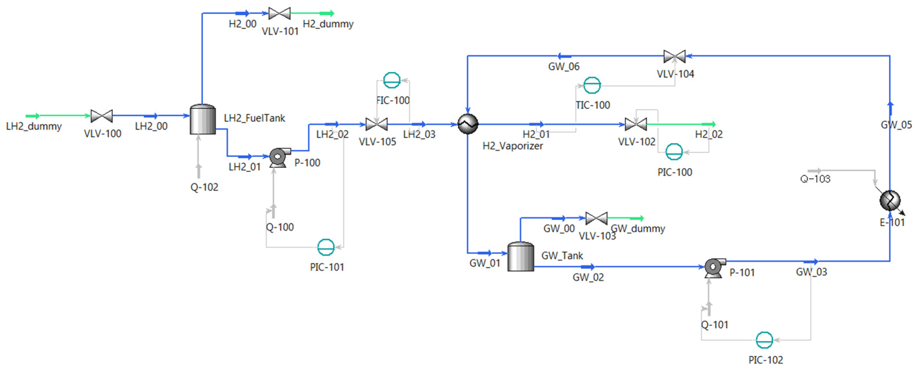
LH2 is stored at an extremely low saturation temperature, which is around 20 K at atmospheric pressure. Therefore, it requires a fuel gas supply system (FGSS) to match the supply conditions for fuel cells [22], and additional power for the balance of the plant (BOP power) needs to be supplied to the LH2 FGSS and PEMFC systems. In other words, it means that the BOP power must be provided to meet the power demand requirements. This additional power can be sourced from either the propulsion system or other onboard power plants. Thus, to apply online EMS to LH2-HSPS, the supply of BOP power for producing the required power should be included in the energy management problem. However, existing EMS proposals for HSPS, based on prior research, have only considered cost functions related to the power demand for propulsion, and degradation of fuel cells and batteries without the BOP power of the FGSS and power sources. Therefore, there is a need for research on EMS for systems that use LH2 as a fuel with consideration of BOP power for the LH2 FGSS and the PEMFC system.
Therefore, this study proposes an EMS for LH2-HSPS using deep reinforcement learning. Constructing an EMS that considers both power demand and BOP power based on models of the LH2 FGSS, PEMFC, and battery systems that constitute LH2-HSPS, energy management performance is compared with conventional optimization algorithms, which are DP and sequential quadratic programming (SQP). Furthermore, we assess the optimized operation strategy with the proposed DRL-EMS through sensitivity analysis of key parameters and changes in operating profiles that affect the EMS. This research provides academic contributions by offering an EMS that can be applied to LH2-HSPS and considers the BOP power of the target system, with an analysis of its performance. It is expected to provide meaningful insights into the energy management problems of LH2-based hybrid power systems for various industries in the future. The rest of this study is organized as follows: Section 2 introduces the description of models of the LH2 FGSS, PEMFC, and battery systems. In Section 3, a methodology for energy management is suggested. Section 4 presents the results and discussion, and Section 5 shows the conclusions of this study

2. Model Description

2.1. Description of Target Ship

A Platform Supply Vessel (PSV) is a ship designed to support the transportation, installation, operation, and maintenance of offshore installations. PSVs perform various tasks in offshore environments and are equipped with a dynamic positioning system to control the vessel’s position and direction for safe and stable operations. When dynamic positioning is used to control the vessel in real time, the required power for the target vessel can vary significantly. In ships like PSVs, where the power demand varies significantly over time, online EMS demonstrates superior performance compared to rule-based EMS since it relies on predefined rules for power distribution. Furthermore, when a battery system that allows for charging and discharging of power at desired times is integrated into LH2-HSPS, it can operate the PEMFC system more efficiently when variations of power demand are significant [10].
Therefore, 2 MW-class PSV is selected as the target ship for applying DRL-EMS. The power demand of a PSV is determined based on its operational mode, which includes laden voyage, dynamic positioning operation, partial load voyage, and standby mode. While many research studies are ongoing to predict the required power for varying environmental conditions, this study assumes a general required power profile of PSVs based on the existing literature [23,24,25]. This power profile is utilized as a reference profile for DRL, DP, and SQP (Figure 1a). Additionally, to assess the online performance of DRL-EMS when applied to unknown power profiles not used during training, we considered three additional power profiles as shown in Figure 1b–d.

2.2. Liquid Hydrogen Fuel Gas Supply System

The LH2 FGSS plays a role in vaporizing the stored LH2 and supplying fuel to meet the pressure and temperature conditions required by the PEMFC system. This system consists of a fuel tank for storing LH2, a pump for transferring LH2, an ethylene glycol/water (GW) mixture system for supplying thermal energy, valves, and controllers. When the fuel tank volume is not large, or transient states in the FGSS do not occur frequently, there is an advantage to reducing the risk of hydrogen leaks and not requiring redundancy units by installing a pressure build-up unit that pressurizes the tank to pressure of a certain level using an external heat source instead of the LH2 pump [22]. However, since the PSV experiences significant fluctuations in the output of the LH2 FGSS and PEMFC system, it is assumed a pump-type FGSS to ensure a stable fuel supply.
In this study, the LH2 FGSS is simulated using Aspen HYSYS software to calculate the changes in hydrogen fuel flow rate, pressure, and temperature due to fluctuations in the output of the PEMFC system during operation. Figure 2 shows the implemented LH2 FGSS in Aspen HYSYS and Table 1 represents key design specifications for each piece of equipment.
The Modified Benedict–Webb–Rubin (MBWR) and Peng–Robinson equations are used for the hydrogen and GW streams, respectively, and the composition of the hydrogen stream is assumed to be 99.8% para-hydrogen and 0.02% ortho-hydrogen based on mole fractions. The sizing of key equipment for dynamic simulation is performed considering the maximum H2 flow rate for the maximum output of the PEMFC system. In particular, the volume of the LH2 fuel tank is determined as 100 m3 based on the required fuel quantity for a case where the PEMFC system, the main power source generates all required power during operation, following the IGF Code [26]. The LH2 vaporizer is simulated as a shell and tube-type heat exchanger. The governing equations for each piece of equipment used in the calculations are shown in Equations (1)–(8) [27,28].
Tanks
d m f , t a n k d t = i m ˙ f , i n , i j m ˙ f , o u t , j
  • m f , t a n k : Mass of fluid stored in the tank
  • m ˙ f , i n , i : Mass flow rate of fluid i entering the tank
  • m ˙ f , o u t , j : Mass flow rate of fluid j exiting the tank
d E f , t a n k d t = i m ˙ f , i n , i h f , i n , i j m ˙ f , o u t , j h f , o u t , j
  • E f , t a n k : Internal energy of fluid stored in the tank
  • h f , i n , i : Enthalpy of fluid i entering the tank
  • h f , o u t , j : Enthalpy of fluid j exiting the tank
Pumps
P p u m p = m ˙ f ( p f , o u t p f , i n ) ρ f η p u m p
  • P p u m p : Power consumption of the pump
  • p f , o u t : Outlet pressure of fluid
  • p f , i n : Inlet pressure of fluid
  • ρ f : Density of fluid
  • η p u m p : Efficiency of the pump
Heat Exchanger
d ( m f , s h e l l h f , s h e l l , o u t ) d t = m ˙ f , s h e l l h f , s h e l l , i n h f , s h e l l , o u t Q ˙ H X
  • m f , s h e l l : Mass of accumulated fluid in shell side
  • m ˙ f , s h e l l : Mass flow rate of fluid in shell side
  • h f , s h e l l , i n : Enthalpy of entering fluid in shell side
  • h f , s h e l l , o u t : Enthalpy of exiting fluid in shell side
  • Q ˙ H X : Heat flow rate between shell and tube side
d ( m f , t u b e h f , t u b e , o u t ) d t = m ˙ f , t u b e h f , t u b e , i n h f , t u b e , o u t + Q ˙ H X
  • m f , t u b e : Mass of accumulated fluid in tube side
  • m ˙ f , t u b e : Mass flow rate of fluid in tube side
  • h f , t u b e , i n : Enthalpy of entering fluid in tube side
  • h f , t u b e , o u t : Enthalpy of exiting fluid in tube side
Q ˙ H X = U A T L M
  • U : Overall heat transfer coefficient
  • A : Heat transfer area
  • Δ T L M : Logarithmic temperature difference
Heater
P h e a t e r = m ˙ f ( h f , o u t h f , i n ) η h e a t e r
  • P h e a t e r : Power consumption of the heater
  • η h e a t e r : Efficiency of the heater
Valves
m ˙ f = k ρ f ( p f , o u t p f , i n )
  • k : Pressure drop coefficient

2.3. Description of Power Sources

The PEMFC stack is modeled based on electrochemistry to simulate the voltage, current, and stack temperature. Also, the model can calculate the additional power required for the BOP. After modeling individual cells using Equations (9)–(13) [29,30], cell models are connected to simulate the 2 MW class PEMFC system. A schematic diagram of the PEMFC system can be shown in Figure 3. The current flowing through the PEMFC stack is calculated based on the supplied hydrogen flow rate, and this is used to determine the voltage applied to the PEMFC stack, thus calculating the system’s output. Additionally, the power consumption of BOP is determined by the power consumption of the air compressor, H2 compressor, GW radiator, and air fan. All calculations are performed using Simulink/Simscape and Aspen HYSYS, and the developed PEMFC stack model was validated against the polarization curve of NEDSTACK’s FCS 10-XXL product [31]. It should be noted that the output of the PEMFC system produced through the combination of stacks and the BOP power for the system can vary slightly depending on the system’s configuration and the detailed specifications of each piece of equipment. In this study, it was assumed that the flow rate, pressure, and temperature conditions of hydrogen supplied to multiple stacks are consistent, and the BOP power was calculated for the entire PEMFC system.
V c e l l = V n e r n s t V a c t V o h m V c o n c
  • V c e l l : Cell voltage
  • V n e r n s t : Nernst voltage
  • V a c t : Activation loss
  • V o h m : Ohmic loss
  • V c o n c : Concentration loss
V n e r n s t = G H 2 O 2 F + R T 2 F l n ( α H 2 , a α O 2 , a 0.5 α H 2 O , c )
  • F : Faraday constant
  • G H 2 O : Gibbs free energy of water
  • R : Gas constant
  • T : Temperature
  • α H 2 , a : Chemical activity of hydrogen at anode side
  • α O 2 , a : Chemical activity of oxygen at anode side
  • α H 2 O , c : Chemical activity of water at cathode side
V a c t = R T 2 θ a c t F l n ( j c e l l j 0 )
  • θ a c t : Coefficient of activation loss
  • j c e l l : Current density
  • j 0 : Reference current density
V o h m = i c e l l R o h m
  • i c e l l : Current
  • R o h m : Electric resistance
V c o n c = m c o n c e x p ( n c o n c j c e l l )
  • m c o n c : Coefficient of concentration loss
  • n c o n c : Coefficient of concentration loss
On the other hand, PEMFC stacks installed in ships or mobility applications have a relatively shorter lifetime compared to stationary applications. If there are rapid output changes in the stacks and if very high and low outputs continue, degradation is accelerated, leading to higher replacement costs over the lifespan. Therefore, it is necessary to consider the decreasing lifespan of PEMFC stacks during operation in energy management problems. P. Pei et al. (2008) investigated the effects of load-changing cycles, start/stop cycles, idling time, and high-power load conditions on the lifespan of automotive PEMFC through experimental research and proposed a degradation model based on arithmetic equations [32]. Additionally, Y. Liu et al. (2020) examined rule-learning-based EMS for fuel-cell hybrid vehicles using the mentioned degradation model and reported an effective reduction in hydrogen consumption and an increase in the lifespan of PEMFC stacks [14]. Similarly, in this study, the proposed model is used to calculate the effective degradation cost of the PEMFC system with Equation (14) and parameters in Table 2.
V l o s s , F C = k p { k 1 t 1 + k 2 n 1 + k 3 t 2 + k 4 t 3 + β }
The power charging and discharging of the battery system are simulated by connecting cell models based on the Equivalent Circuit Model (ECM) in series and parallel. Similar to the PEMFC system, a heat management system using GW as a thermal medium is modeled using Simulink/Simscape. A water-cooling type is a heat management system commonly used in batteries to dissipate heat generated during charging and discharging. When this type is used as a heat management system, a liquid coolant, typically water or GW, is circulated through a series of channels and tubes that are embedded within the battery pack or attached to its exterior surface. Once the coolant has been heated by the batteries, it is circulated to a radiator where it is cooled by air or another coolant. The cooled coolant is then circulated back into the battery, where it absorbs heat and the cycle repeats. Water-cooling systems offer several advantages over other types of heat management systems, such as air-cooling or passive cooling. They can dissipate heat more efficiently and effectively, which allows the battery to operate at higher power levels for longer periods of time. Additionally, water-cooling systems can be designed to be more compact and lightweight than other types, which is particularly important in applications where space and weight are limited, such as ship propulsion.
The used ECM consists of a 4-parameters model, which includes one voltage source, two resistors, and one capacitor. Each parameter was calculated as a two-dimensional look-up table based on the state of charge (SOC) and temperature of the battery cell, referencing the research results of Huria et al. (2012) [33]. The heat management system of the battery system using GW as a thermal medium was modeled using Equations (15)–(17).
m p l a t e c p , p l a t e d T p l a t e d t = k A p l a t e T b a t t e r y T p l a t e L h G W A c h ( T p l a t e T G W )
  • m p l a t e : Mass of the cold plate
  • c p , p l a t e : Specific heat of the cold plate
  • k : Thermal conductivity
  • h G W : Convective heat transfer coefficient of GW
  • A c h : Heat transfer area of cooling channels
N u = f a v g 8 ( R e a v g 1000 ) P r a v g 1 + 12.7 f a v g 8 ( P r a v g 2 3 1 )
  • f a v g : Friction factor with averaged condition between the inlet and outlet
  • R e a v g : Reynolds number with averaged condition between the inlet and outlet
  • P r a v g : Prandtl number with averaged condition between the inlet and outlet
f = 1 [ 1.8 l o g 10 6.9 R e + 1 3.7 r D 1.11 ] 2
  • r : Roughness of tube
  • D : Diameter of tube
Lithium iron phosphate (LiFePO4, LFP)-based battery cells have the disadvantage of relatively low gravimetric energy density. However, they are relatively inexpensive because they do not use expensive materials like cobalt and nickel. Additionally, they have a long lifespan under conditions where the maximum C-rate is not high. Moreover, they are widely used in large-scale applications such as ships and space industries due to their low risk of explosion or fire [34,35]. Therefore, in this study, it is assumed that the target battery system uses LFP-based cells.
J. Wang et al. (2011) conducted experimental research to investigate capacity fade in graphite-LFP cells by varying cell temperature, depth of discharge, and C-rate. They found that at low C-rates, capacity fade was significantly affected by time and temperature, while at high C-rates, the effect of the C-rate became more pronounced. Furthermore, based on the experimental results, they generalized the power-law equation for capacity fade [35]. Similar to the PEMFC system, we used the following degradation model based on existing research results to consider the degradation rate of battery cells in the energy management problem, as shown in Equation (18) with parameters in Table 3.
E l o s s , b a t = A h z B 1 / z e x p ( E a + α C C r a t e z R T ) E l o s s , b a t ( z 1 ) / z
  • A h : Ah-throughput
  • E l o s s , b a t : Capacity loss
  • C r a t e : C-rate

2.4. System Efficiency

Using the models for LH2 FGSS and the PEMFC system, the efficiency of the target system is approximated based on the power of the PEMFC system using Equation (19), which includes hydrogen consumption with BOP power. Additionally, the calculated system efficiency is used to estimate hydrogen consumption in the energy management problem. Since the BOP power from the battery system is not significantly high compared to the LH2 FGSS and PEMFC system, we assumed the battery system can generate all auxiliary power during operation of the PSV.
η s y s t e m P F C = P F C , t o t a l P F C P F G S S , B O P P F C P F C , B O P P F C m ˙ H 2 P F C · L H V H 2
  • η s y s t e m : System efficiency
  • P F C : Output power of the PEMFC system excluding BOP power
  • P F C , t o t a l : Output power of the PEMFC system
  • P F G S S , B O P : BOP power of the LH2 FGSS
  • P F C , B O P : BOP power of the PEMFC system
Figure 4 depicts the system efficiency of the LH2-HSPS calculated through Equation (19) and the required mass flow rate of hydrogen as a function of fraction for the maximum output of the PEMFC system, which is 2 MW. The maximum efficiency of the LH2-HSPS is found to be approximately 59%, occurring within the 10~20% fraction of output power. Additionally, it is confirmed that BOP power reduces the system efficiency of the LH2-HSPS by approximately 7%, resulting in a difference of 17.5 kg/h in the required hydrogen mass flow rate based on the maximum output power.

3. Methodology of Energy Management

The energy management problem of the LH2-HSPS addressed in this study takes the output of the PEMFC system as the control variable. As mentioned earlier, it is assumed that all BOP power for the LH2 FGSS and the PEMFC system is generated by the PEMFC system. Additionally, the reward function (for DRL-EMS) or objective function (for DP-EMS and SQP-EMS) of this problem considers operating expenditure (OPEX) with hydrogen consumption and the degradation of the PEMFC and battery systems. Constraints are imposed on the state of charge (SOC) of the battery system and the power demand of the PSV. To summarize, the problem can be described with Equations (20)–(28). Detailed parameters for solving energy management problems can be shown in Table 4.
P F C * t = a r g m i n ( C H 2 t + C F C , d e g t + C b a t , d e g t + C b a t , e q t )
s . t .
C H 2 t = C o s t H 2 · m ˙ H 2 ( P F C t ) · t
C F C , d e g t = C o s t F C · P F C , m a x · V l o s s , F C ( P F C t ) E O L F C · t
C b a t , d e g t = C o s t b a t · E b a t · E l o s s , b a t ( P F C t , P r e q t ) E O L b a t
C b a t , e q t = C o s t H 2 · s L H V H 2 · P b a t t · { 1 S O C t S O C r e f 0.5 S O C m a x S O C m i n } p t
P r e q t = P F C t + P b a t t { P a u x , F G S S t + P a u x , F C t + P a u x , b a t t }
S O C 0 = S O C r e f
S O C t [ S O C m i n , S O C m a x ]
P F C t [ P F C , m i n , P F C , m a x ]
  • C H 2 : Cost for hydrogen consumption
  • C F C , d e g : Equivalent cost for PEMFC degradation
  • C b a t , d e g : Equivalent cost for battery degradation
  • C b a t , e q : Equivalent cost for battery power
  • s : Equivalence factor

3.1. Deep Reinforcement Learning

The Deep Q-network (DQN) algorithm used in this study is based on the Q-learning algorithm widely used in reinforcement learning. It effectively trains agents for high-dimensional or large state and action spaces by approximating Q-values for each state and action obtained through the Q-function, typically defined as the following Equation (29), using a neural network [39]. The Q-values computed through the Q-function represent the expected value of the return (i.e., cumulative reward) that can be obtained when taking action (a) in a specific state (s). In the case of the Q-learning algorithm, training occurs through interaction with the environment, and Q-values for all actions in all states are continuously updated. Once the learning is completed, the agent can choose the optimal action in each state.
Q π s , a = E π G t S t = s , A t = a = E π [ R t + 1 + γ q π s , a | S t = s , A t = a ]
  • Q π : State-action value function with policy π
  • G t : Return after time t
  • S t : State at time t
  • A t : Action at time t
  • R t + 1 : Reward at time t + 1
  • γ : Discount factor
One of the features of the DQN algorithm is the use of separate prediction and target networks. During training, the prediction network is continuously updated, while the target network is updated less frequently. The target network provides target Q-values for the loss function, defined as follows, at each training step. Additionally, the target network mitigates the overestimation of Q-values approximated by the neural network by providing stable target Q-values. During each episode, the neural network is trained through random sampling from the experience pool. The gradient of the loss function is computed, and the optimal action value is obtained using the gradient descent algorithm with Equation (30). The loss function represents how optimally the current prediction network approximates the action value. Training proceeds by continuously updating both the target and prediction networks. Figure 5 represents the overview of the DQN algorithm and detailed hyperparameters can be shown in Table 5.
L θ = E [ R + γ m a x Q s , a ; θ Q s , a ; θ 2 ]
L θ : Loss function with parameter θ .

3.2. Benchmark Algorithms

To verify and assess the optimality of the PEMFC system’s output determined through DRL-EMS and the total OPEX obtained, the results are compared with the DP algorithm for the same energy management problem. DP is a widely used algorithm for continuous-time control problems, including energy management in hybrid propulsion systems. The dynamic model considered in this study evolves over time and, following the principle of optimality, the DP algorithm calculates the optimal cost-to-go function for all time and state nodes through backward calculation. Based on this, it provides optimal control results through forward calculation [40].
As mentioned in Section 1, the DP algorithm is advantageous for global optimization, but as the number of state and control variables increases, the computational complexity escalates rapidly, making it unsuitable for online EMS applications. Therefore, to assess the online energy management performance of RL-EMS, an online EMS based on the SQP algorithm and ECMS (SQP-EMS) is additionally developed [41,42].

4. Results and Discussion

Before analyzing the optimal operational strategy applied to LH2-HSPS by DRL-EMS, the optimization results with DP-EMS and SQP-EMS algorithms are compared to evaluate the performance of these algorithms, as shown in 
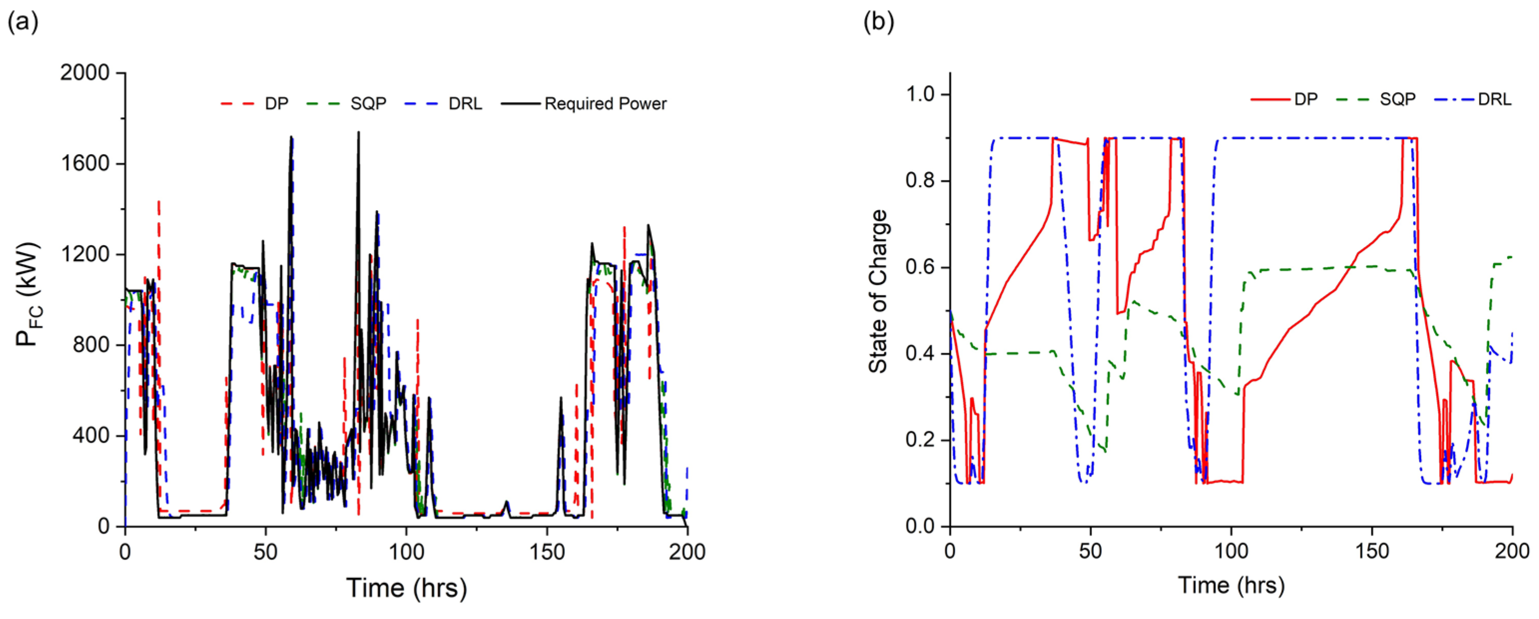
Table 6. It is observed that both DRL-EMS and SQP-EMS resulted in 0.2% and 10.9% higher OPEX, respectively, compared to DP-EMS. The significant impact on the performance of these two algorithms was attributed to the equivalent degradation cost of the PEMFC system. The degradation rate calculated through the model exhibited discontinuities at low-load operations (<40 kW) and high-load operations (>1800 kW), which SQP-EMS, based on gradient descent, failed to sufficiently consider. Additionally, DRL-EMS yielded OPEX values nearly identical to DP-EMS, indicating that the effective utilization of the battery system allowed DP-EMS to calculate slightly lower OPEX. Meanwhile, Figure 6 shows the changes in the calculated PEMFC system output and SOC when each EMS is applied. As mentioned earlier, it can be observed that DP-EMS is most effectively utilizing the battery system based on the SOC changes, while SQP-EMS appears to underutilize the installed battery system in situations where future required power is uncertain.
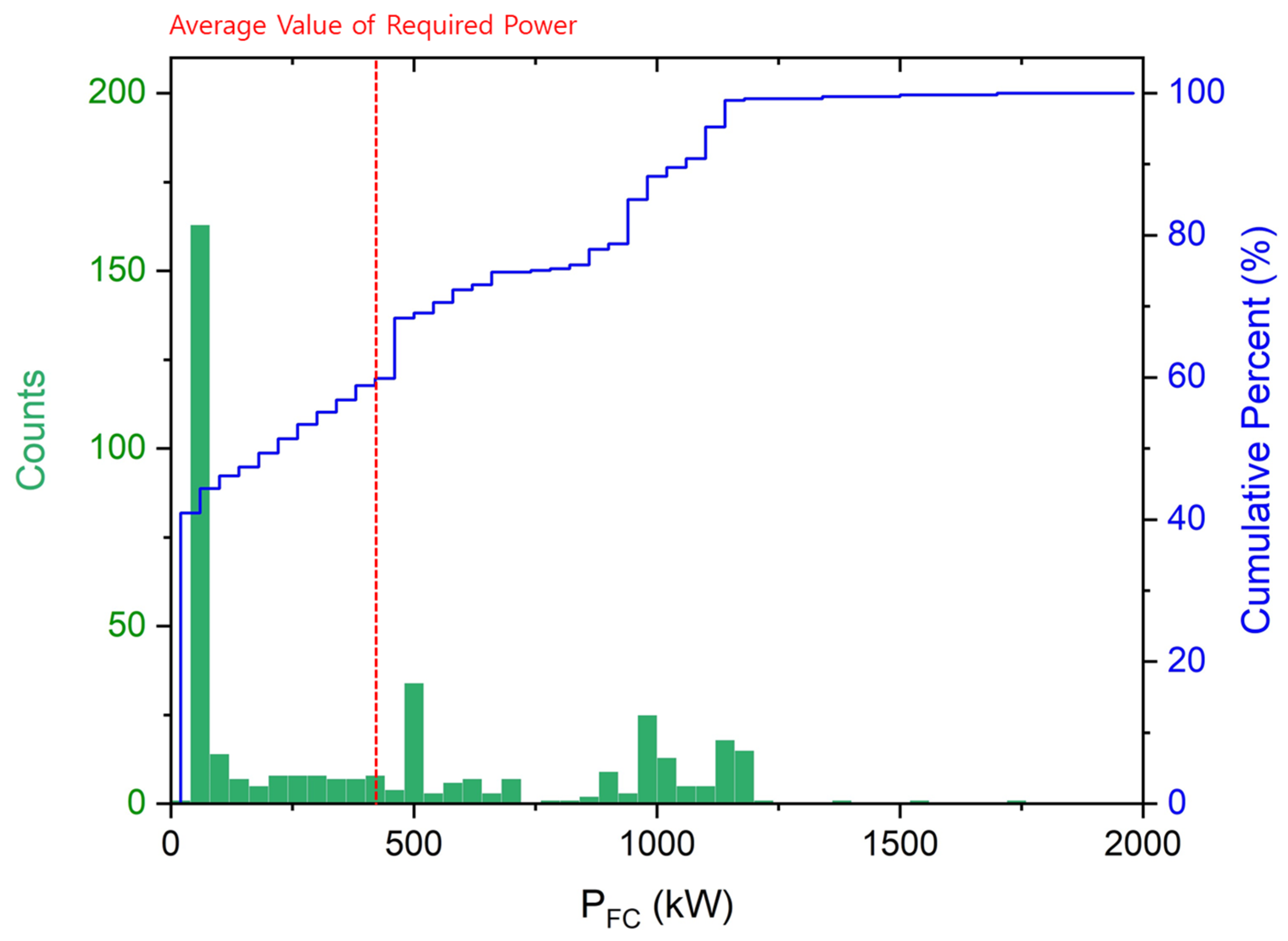
Figure 7 shows a histogram and cumulative percent of the PEMFC system’s power output counted in 30 min intervals using DRL-EMS for the reference operating profile. It is evident that, due to the decreasing LH2-HSPS LHV efficiency as the PEMFC system output increases, the optimization has resulted in operation times at power levels lower than the average required power (~420 kW) for about 60% of the time. On the other hand, the system efficiency plot reveals that the system efficiency is highest when the PEMFC system output is 20% or less of its maximum value. The fraction of this average required power is 21%. In other words, DRL-EMS has been trained to operate within the maximum efficiency range of the PEMFC system as much as possible.
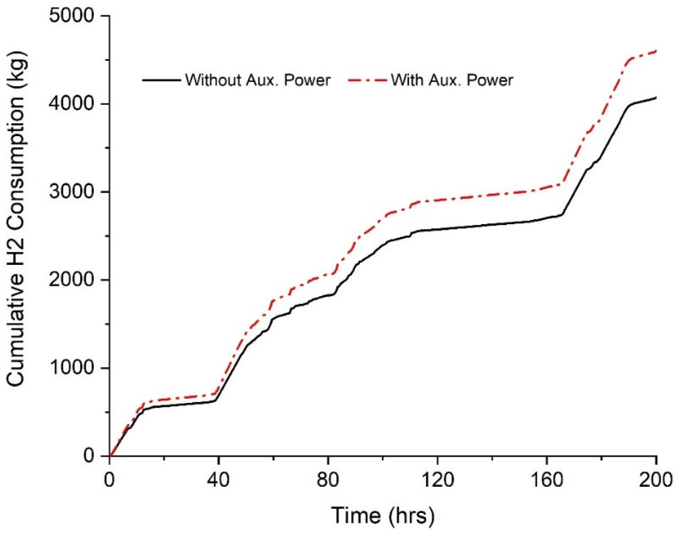
In the previous results, it is confirmed that approximately 90% of OPEX was incurred through hydrogen fuel consumption, indicating the necessity of saving hydrogen consumption for the efficient operation of LH2-HSPS. 
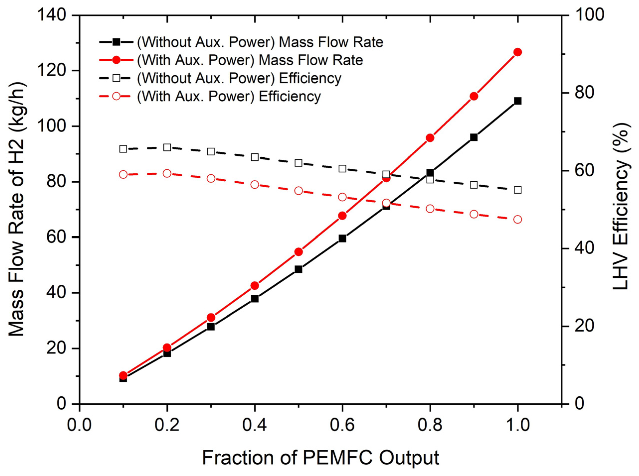
Figure 8 represents cumulative hydrogen consumption when using the same DRL-EMS but distributing power based on PEMFC stack efficiency instead of system efficiency. Without considering of auxiliary power, a total of 4074 kg of fuel was consumed, which is approximately 11% lower compared to the system efficiency-based calculation. Since ships have limited space for equipment relative to their capacity, the appropriate sizing of each piece of equipment should be determined in the design phase. When using LH2 as fuel without a separate external power plant to supply BOP power required for ship propulsion, power must be supplied through the PEMFC system for propulsion. In this case, as explained earlier, there is a significant difference of about 11% in fuel consumption per operation, affecting the volume of the fuel tank. Therefore, the volume of the LH2-powered ship’s fuel tank to be built in the future should be determined by thoroughly reviewing the system efficiency of LH2-HSPS.
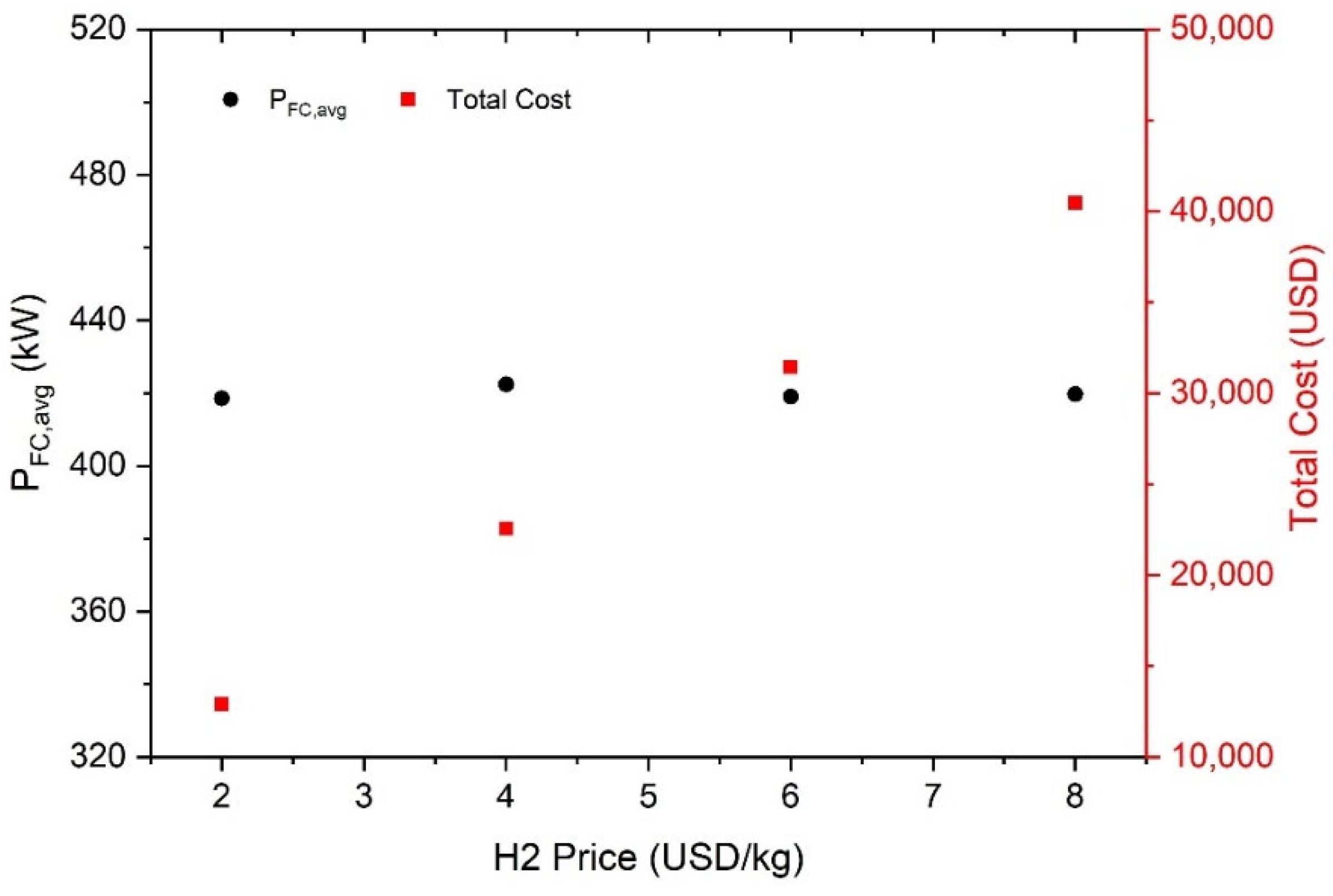
To further analyze the optimal energy management performance of the DRL-EMS, two sensitivity analyses are conducted. Among them, Figure 9 represents the energy management results with different hydrogen fuel costs, which has the most significant impact on LH2-HSPS’s OPEX. The training is performed for unit hydrogen fuel costs of 2, 4, and 6 USD/kg. The calculation results showed that the hydrogen fuel price exhibited a linear relationship with OPEX compared to the reference case. Additionally, when examining the average power generated by the PEMFC system in each case, it is found that nearly identical average power is produced in all cases. This implies that the change in hydrogen fuel price does not determine the operational strategy of LH2-HSPS, and the decrease in OPEX is attributed to changes in hydrogen fuel prices rather than changes in the operating mode.
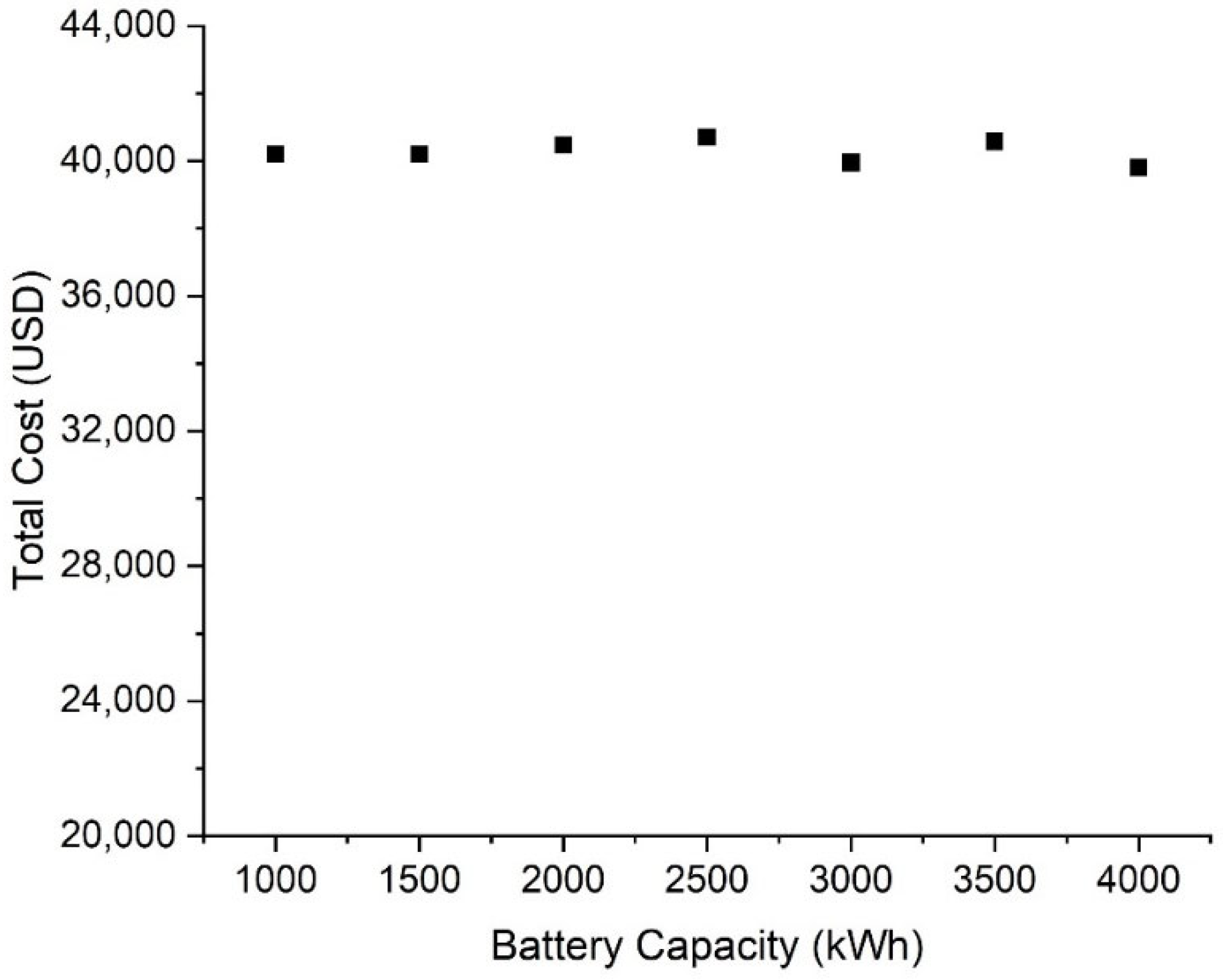
Furthermore, a sensitivity analysis of DRL-EMS performance with respect to battery system capacity can be shown in Figure 10. Since the equivalent degradation cost of the battery system does not account for a significant portion of OPEX, LH2-HSPS’s OPEX does not exhibit significant changes for all investigated battery system capacities. It showed a maximum difference of approximately 2.2% compared to the reference case (i.e., capacity of 2000 kWh). The increase in battery system capacity leads to a trade-off relationship with equivalent degradation cost under the same charging and discharging conditions due to the combined effects of system cost increase and C-rate decrease. Consequently, it is determined that this did not have a significant impact on the overall OPEX.
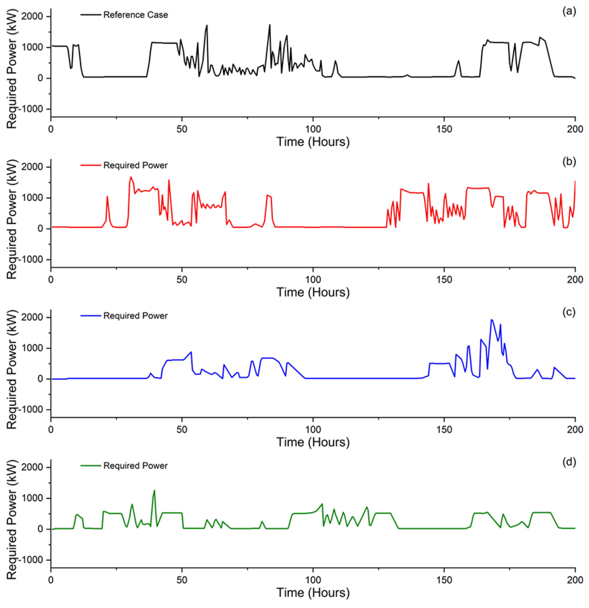
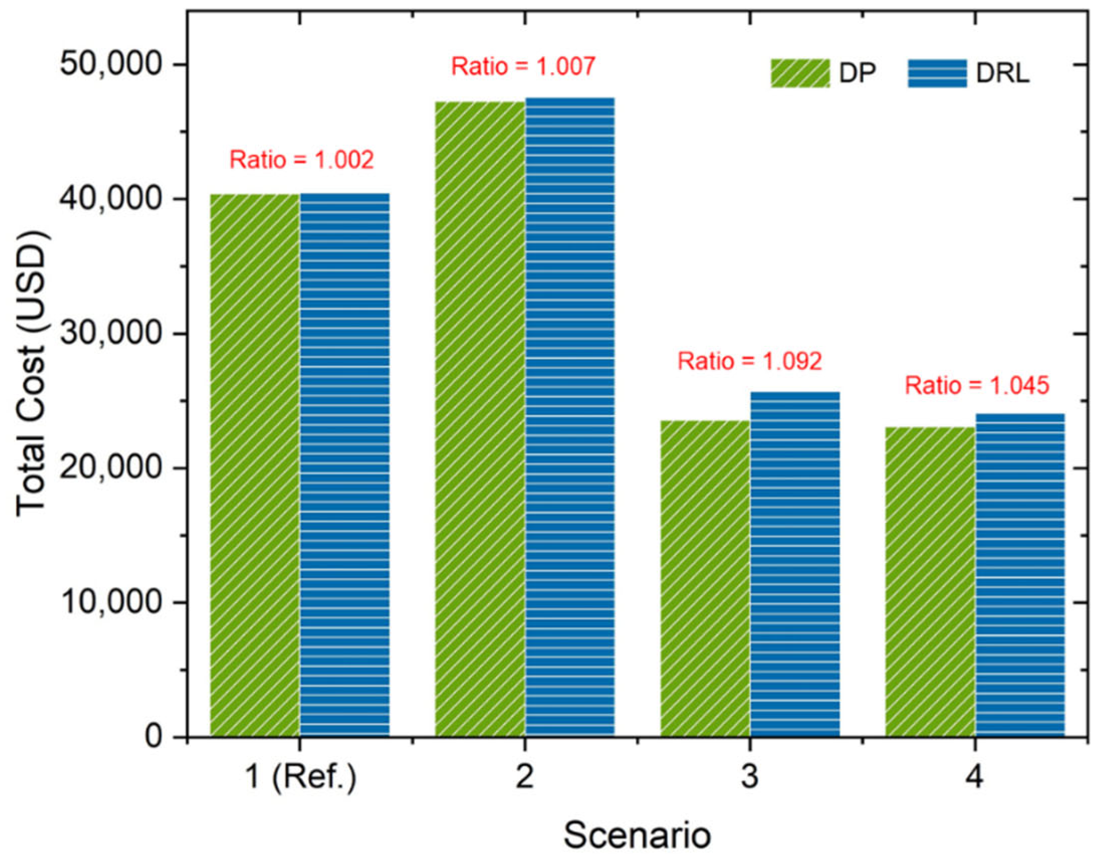
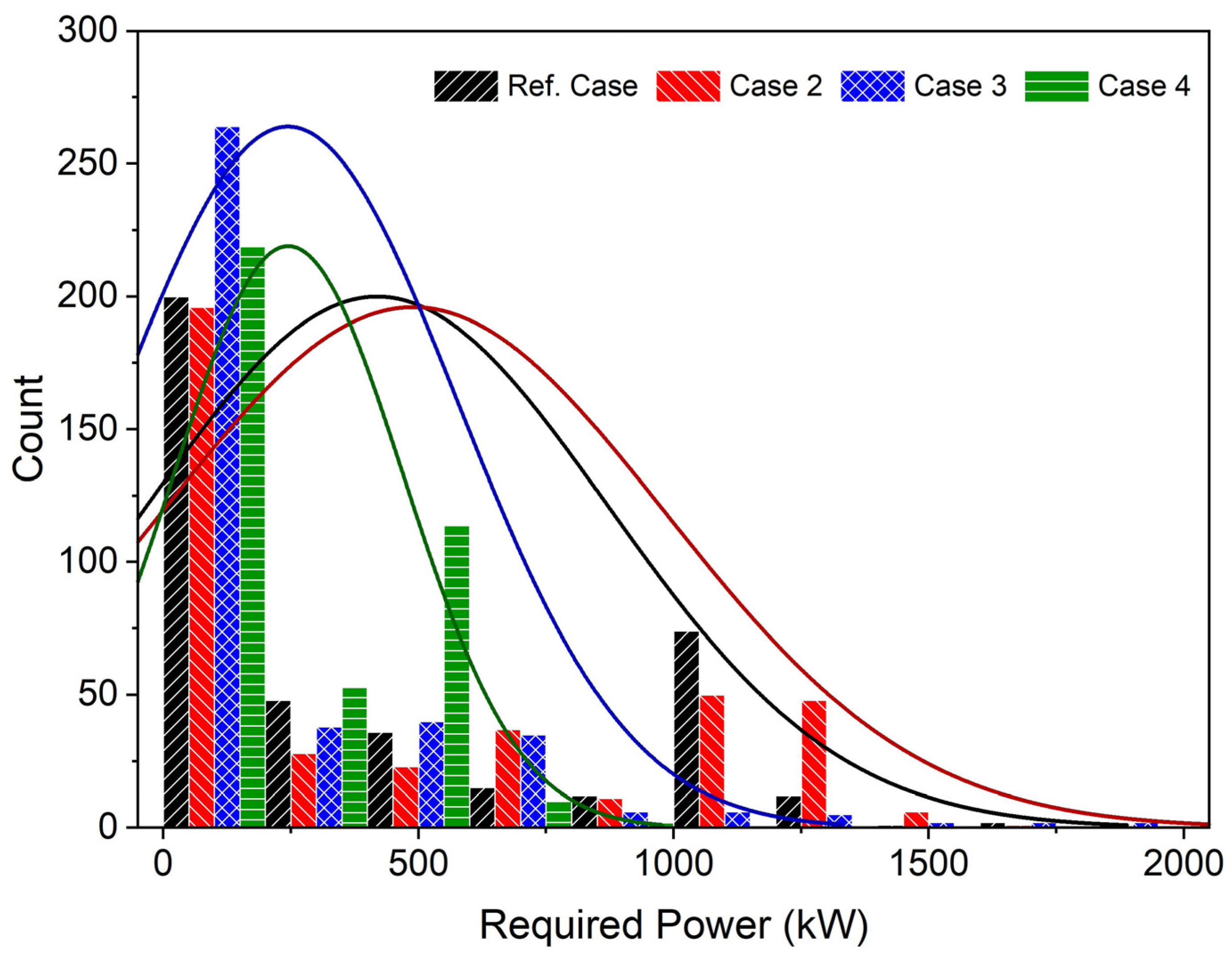
Finally, considering that various operation modes can occur during a vessel’s operation, the performance of DRL-EMS is evaluated on three additional operation profiles not used in the training. The calculation results showed that, depending on the cases, OPEX is higher by approximately 0.7% to 9.2% compared to DP-EMS (Figure 11). Case 2, which demonstrated performance similar to DP-EMS, exhibited a distribution of power demand in the histogram that closely resembled that of DP-EMS. On the other hand, Case 3 and Case 4, which showed significant differences from DP-EMS, have distinct distributions of power demand compared to the reference case (Figure 12). In essence, it is concluded that DRL-EMS’s performance could decrease when significantly different operations occurred compared to the required power variations used in its training. However, despite being arbitrary power demands not used in the training of DRL-EMS, the fact that they still show a maximum difference of up to 9.2% compared to DP-EMS indicates that DRL-EMS exhibits remarkable optimization performance, as compared to the results of SQP-EMS (Table 6). Also, one of DRL-EMS’s advantages is its ability to use an agent trained under various operating conditions directly in actual operations. By continuously updating neural networks based on data obtained from equipment installed on real vessels and conducting ongoing training, it is expected that DRL-EMS can provide an effective EMS for diverse operations.

5. Conclusions

This study proposed a deep reinforcement learning-based energy management strategy (DRL-EMS) that can be applied to a liquid hydrogen-powered hybrid electric ship propulsion system (LH2-HSPS) and compares and analyzes its performance with EMS using dynamic programming (DP-EMS) and sequential quadratic programming (SQP-EMS). The study also investigated the optimal operation strategy for LH2-HSPS. Modeling of LH2-HSPS was conducted to calculate the optimal operating expenditure (OPEX) considering BOP power for the LH2 FGSS and PEMFC system within LH2-HSPS. The reward function of the energy management problem consists of hydrogen consumption, degradation of the PEMFC and battery systems, and equivalent consumption of the battery system. DRL-EMS demonstrated superior global and real-time optimization performance compared to DP-EMS and SQP-EMS. Additionally, additional performance analysis was conducted for three operation profiles not used in training, revealing OPEX values 0.7% to 9.2% higher than DP-EMS. Meanwhile, DRL-EMS was trained to operate in the maximum efficiency region of the PEMFC system for 60% of LH2-HSPS operation time. It was observed that changes in hydrogen fuel cost significantly affect OPEX of the LH2-HSPS but do not induce changes in operation strategy. Furthermore, variations in battery system capacity result in a trade-off relationship between equipment cost and C-rate, affecting equivalent degradation cost, but not causing significant changes in OPEX of the LH2-HSPS.
The results of this study suggest that the proposed energy management methods and system operation strategies can serve as guidelines for the economic design and efficient operation of hybrid power systems using LH2 as a fuel.

Author Contributions

Conceptualization, W.J.; methodology, W.J.; validation, W.J.; formal analysis, W.J. and D.C.; investigation, W.J. and D.C.; resources, W.J. and D.C.; data curation, W.J; writing—original draft preparation, W.J.; writing—review and editing, W.J. and D.C.; visualization, W.J.; supervision, D.C. All authors have read and agreed to the published version of the manuscript.

Funding

This work was supported by the Korea Institute of Energy Technology Evaluation and Planning (KETEP) grant funded by the Korean government (MOTIE) (20213030030290, Design and Verification of Liquid Hydrogen Fuel Cell Ships).

Institutional Review Board Statement

Not applicable.

Informed Consent Statement

Not applicable.

Data Availability Statement

Not applicable.

Conflicts of Interest

The authors declare no conflict of interest.

Abbreviations

Nomenclature
A Area
a Action
B Coefficient for battery degradation
C r a t e C-rate
C Cost
c p Specific heat
E Internal energy
E O L End of life
E a Activation energy
E l o s s Capacity loss
f Friction factor
G Gibbs free energy
G t Return at time t
h Enthalpy
i Current
j Current density
k Pressure drop coefficient or thermal conductivity
k p , k 1 , k 2 , k 3 , k 4 Coefficients for PEMFC degradation
L H V Lower heating value
m Mass
m c o n c Coefficient for concentration loss
m ˙ Mass flow rate
n c o n c Coefficient for concentration loss
P Power
p Pressure
Q ˙ Heat flow rate
q State-action value function
r t Return at time t
R Gas constant
R o h m Electric resistance
S O C State of charge
s State
T Temperature
U Overall heat transfer coefficient
V Voltage
z Coefficient for battery degradation
α C Coefficient for battery degradation
α Chemical activity
β Coefficient for PEMFC degradation
η Efficiency
ρ Density
θ Coefficient for activation loss or parameter set
γ Discount factor
Abbreviations
BOPBalance of plant
CO2Carbon dioxide
DPDynamic programming
DQNDeep Q-network
DRLDeep reinforcement learning
ECMEquivalent circuit model
EEDIEnergy efficiency design index
EMSEnergy management strategy
FGSSFuel gas supply system
GHGGreenhouse gas
GWEthylene glycol/water mixture
HEVHybrid electric vehicle
HSPSHybrid electric ship propulsion system
IGF CodeInternational code of safety for ships using gases or other low-flashpoint liquids as fuel
IMOInternational maritime organization
LFPLithium iron phosphate
LH2Liquid hydrogen
LHVLower heating value
LNGLiquefied natural gas
MBWRModified Benedict–Webb–Rubin
OPEXOperating expenditure
PEMFCPolymer electrolyte membrane fuel cell
PMPPontryagin’s minimum principle
PSVPlatform supply vessel
RLReinforcement learning
SOCState of charge
SQPSequential quadratic programming

References

  1. International Maritime Organization. Initial IMO Strategy on Reduction of GHG Emissions from Ships; International Maritime Organization: London, UK, 2018. [Google Scholar]
  2. Van Hoecke, L.; Laffineur, L.; Campe, R.; Perreault, P.; Verbruggen, S.W.; Lenaerts, S. Challenges in the Use of Hydrogen for Maritime Applications. Energy Environ. Sci. 2021, 14, 815–843. [Google Scholar] [CrossRef]
  3. Balcombe, P.; Brierley, J.; Lewis, C.; Skatvedt, L.; Speirs, J.; Hawkes, A.; Staffell, I. How to Decarbonise International Shipping: Options for Fuels, Technologies and Policies. Energy Convers. Manag. 2019, 182, 72–88. [Google Scholar] [CrossRef]
  4. Bouman, E.A.; Lindstad, E.; Rialland, A.I.; Strømman, A.H. State-of-the-Art Technologies, Measures, and Potential for Reducing GHG Emissions from Shipping—A Review. Transp. Res. D Transp. Env. 2017, 52, 408–421. [Google Scholar] [CrossRef]
  5. Elkafas, A.G.; Rivarolo, M.; Gadducci, E.; Magistri, L.; Massardo, A.F. Fuel Cell Systems for Maritime: A Review of Research Development, Commercial Products, Applications, and Perspectives. Processes 2023, 11, 97. [Google Scholar] [CrossRef]
  6. Herrmann, C.; Kara, S.; Albrecht, S.; Fischer, M.; Leistner, P.; Schebek, L. Sustainable Production, Life Cycle Engineering and Management; Springer: Berlin/Heidelberg, Germany, 2020. [Google Scholar]
  7. Camilo Gomez Trillos, J.; Wilken, D.; Brand, U.; Vogt, T. HySeas III: The World’s First Sea-Going Hydrogen-Powered Ferry-A Look at Its Technical Aspects, Market Perspectives and Environmental Impacts. In Proceedings of the ELMAR/26. REGWA Symposium 2019, Stralsund, Germany, 6 September 2019. [Google Scholar]
  8. Mikkola, J.; Bellot, A.; Haxhiu, A.; Angrisani, M.L.; Laravoire, V.; Saeter, H.-K.; Berg, P. FLAGSHIPS: Deploying Two Hydrogen Vessels in Europe-Design Phase. In Proceedings of the SNAME Maritime Convention 2021, Providence, RI, USA, 25–29 October 2021. [Google Scholar]
  9. Antonopoulos, S.; Visser, K.; Kalikatzarakis, M.; Reppa, V. MPC Framework for the Energy Management of Hybrid Ships with an Energy Storage System. J. Mar. Sci. Eng. 2021, 9, 993. [Google Scholar] [CrossRef]
  10. Gao, D.; Jiang, H.; Shi, W.; Wang, T.; Wang, Y. Adaptive Equivalent Consumption Minimization Strategy for Hybrid Electric Ship. Energy Sci. Eng. 2022, 10, 840–852. [Google Scholar] [CrossRef]
  11. Lee, H.; Cha, S.W. Reinforcement Learning Based on Equivalent Consumption Minimization Strategy for Optimal Control of Hybrid Electric Vehicles. IEEE Access 2021, 9, 860–871. [Google Scholar] [CrossRef]
  12. Musardo, C.; Rizzoni, G.; Guezennec, Y.; Staccia, B. A-ECMS: An Adaptive Algorithm for Hybrid Electric Vehicle Energy Management. Eur. J. Control 2005, 11, 509–524. [Google Scholar] [CrossRef]
  13. Du, G.; Zou, Y.; Zhang, X.; Liu, T.; Wu, J.; He, D. Deep Reinforcement Learning Based Energy Management for a Hybrid Electric Vehicle. Energy 2020, 201, 117591. [Google Scholar] [CrossRef]
  14. Liu, Y.; Liu, J.; Zhang, Y.; Wu, Y.; Chen, Z.; Ye, M. Rule Learning Based Energy Management Strategy of Fuel Cell Hybrid Vehicles Considering Multi-Objective Optimization. Energy 2020, 207, 118212. [Google Scholar] [CrossRef]
  15. Xie, S.; Hu, X.; Xin, Z.; Brighton, J. Pontryagin’s Minimum Principle Based Model Predictive Control of Energy Management for a Plug-in Hybrid Electric Bus. Appl. Energy 2019, 236, 893–905. [Google Scholar] [CrossRef]
  16. Deng, K.; Liu, Y.; Hai, D.; Peng, H.; Löwenstein, L.; Pischinger, S.; Hameyer, K. Deep Reinforcement Learning Based Energy Management Strategy of Fuel Cell Hybrid Railway Vehicles Considering Fuel Cell Aging. Energy Convers. Manag. 2022, 251, 115030. [Google Scholar] [CrossRef]
  17. Bassam, A.M.; Phillips, A.B.; Turnock, S.R.; Wilson, P.A. Development of a Multi-Scheme Energy Management Strategy for a Hybrid Fuel Cell Driven Passenger Ship. Int. J. Hydrogen Energy 2017, 42, 623–635. [Google Scholar] [CrossRef]
  18. Tie, S.F.; Tan, C.W. A Review of Energy Sources and Energy Management System in Electric Vehicles. Renew. Sustain. Energy Rev. 2013, 20, 82–102. [Google Scholar] [CrossRef]
  19. Xue, Q.; Zhang, X.; Teng, T.; Zhang, J.; Feng, Z.; Lv, Q. A Comprehensive Review on Classification, Energy Management Strategy, and Control Algorithm for Hybrid Electric Vehicles. Energies 2020, 13, 5355. [Google Scholar] [CrossRef]
  20. Choi, Y.; Kim, J.; Park, S.; Park, H.; Chang, D. Design and Analysis of Liquid Hydrogen Fuel Tank for Heavy Duty Truck. Int. J. Hydrog. Energy 2022, 47, 14687–14702. [Google Scholar] [CrossRef]
  21. Choi, M.; Jung, W.; Lee, S.; Joung, T.; Chang, D. Thermal Efficiency and Economics of a Boil-off Hydrogen Re-Liquefaction System Considering the Energy Efficiency Design Index for Liquid Hydrogen Carriers. Energies 2021, 14, 4566. [Google Scholar] [CrossRef]
  22. Jeong, J.; Seo, S.; You, H.; Chang, D. Comparative Analysis of a Hybrid Propulsion Using LNG-LH2 Complying with Regulations on Emissions. Int. J. Hydrogen Energy 2018, 43, 3809–3821. [Google Scholar] [CrossRef]
  23. Kamala, S.; Chauhan, P.J.; Panda, S.K.; Wilson, G.; Liu, X.; Gupta, A.K. Methodology to Qualify Marine Electrical Propulsion System Architectures for Platform Supply Vessels. IET Electr. Syst. Transp. 2018, 8, 152–165. [Google Scholar] [CrossRef]
  24. Skjong, E.; Arne Johansen, T.; Member, S.; Molinas, M.; Sørensen, A.J. Approaches to Economic Energy Management in Diesel-Electric Marine Vessels. IEEE Trans. Transp. Electrif. 2017, 3, 22–35. [Google Scholar] [CrossRef]
  25. Vieira, G.T.T.; Pereira, D.F.; Taheri, S.I.; Khan, K.S.; Salles, M.B.C.; Guerrero, J.M.; Carmo, B.S. Optimized Configuration of Diesel Engine-Fuel Cell-Battery Hybrid Power Systems in a Platform Supply Vessel to Reduce CO2 Emissions. Energies 2022, 15, 2184. [Google Scholar] [CrossRef]
  26. International Maritime Organization. International Code of Safety for Ships Using Gases or Other Low-Flashpoint Fuels (IGF Code); International Maritime Organization: London, UK, 2015. [Google Scholar]
  27. AspenTech. HYSYS ® 2004.2 Dynamic Modeling; AspenTech: Bedford, MA, USA, 2004. [Google Scholar]
  28. Wang, C.; Ju, Y.; Wang, T.; Zou, S. Transient Performance Study of High Pressure Fuel Gas Supply System for LNG Fueled Ships. Cryogenics 2022, 125, 103510. [Google Scholar] [CrossRef]
  29. Spiegel, G. PEM Fuel Cell Modeling and Simulation Using Matlab; Elsevier: Amsterdam, The Netherlands, 2008. [Google Scholar]
  30. Kim, J.; Lee, S.-M.; Srinivasan, S.; Chamberlin, C.E. Modeling of Proton Exchange. Membrane Fuel Cell Performance with an Empirical Equation. J. Electrochem. Soc. 1995, 142, 2670. [Google Scholar] [CrossRef]
  31. NEDSTACK PRODUCT DATA SHEET FCS 10-XXL Gen 2.9. 2022. Available online: https://nedstack.com/sites/default/files/2022-07/nedstack-fcs-10-xxl-gen-2.9-datasheet-rev01.pdf (accessed on 25 September 2023).
  32. Pei, P.; Chang, Q.; Tang, T. A Quick Evaluating Method for Automotive Fuel Cell Lifetime. Int. J. Hydrog. Energy 2008, 33, 3829–3836. [Google Scholar] [CrossRef]
  33. Huria, T.; Ceraolo, M.; Gazzarri, J.; Jackey, R. High Fidelity Electrical Model with Thermal Dependence for Characterization and Simulation of High Power Lithium Battery Cells. In Proceedings of the IEEE International Electric Vehicle Conference (IEVC), Greenville, SC, USA, 4–8 March 2012. [Google Scholar]
  34. Zhang, W.J. Structure and Performance of LiFePO4 Cathode Materials: A Review. J. Power Sources 2011, 196, 2962–2970. [Google Scholar] [CrossRef]
  35. Wang, J.; Liu, P.; Hicks-Garner, J.; Sherman, E.; Soukiazian, S.; Verbrugge, M.; Tataria, H.; Musser, J.; Finamore, P. Cycle-Life Model for Graphite-LiFePO4 Cells. J. Power Sources 2011, 196, 3942–3948. [Google Scholar] [CrossRef]
  36. Kampker, A.; Heimes, H.; Kehrer, M.; Hagedorn, S.; Reims, P.; Kaul, O. Fuel Cell System Production Cost Modeling and Analysis. Energy Rep. 2023, 9, 248–255. [Google Scholar] [CrossRef]
  37. Jung, W.; Jeong, J.; Kim, J.; Chang, D. Optimization of Hybrid Off-Grid System Consisting of Renewables and Li-Ion Batteries. J. Power Sources 2020, 451, 227754. [Google Scholar] [CrossRef]
  38. Chen, W.-H.; Hsieh, I.-Y.L. Techno-Economic Analysis of Lithium-Ion Battery Price Reduction Considering Carbon Footprint Based on Life Cycle Assessment. J. Clean. Prod. 2023, 425, 139045. [Google Scholar] [CrossRef]
  39. Wu, J.; He, H.; Peng, J.; Li, Y.; Li, Z. Continuous Reinforcement Learning of Energy Management with Deep Q Network for a Power Split Hybrid Electric Bus. Appl. Energy 2018, 222, 799–811. [Google Scholar] [CrossRef]
  40. Sundstrom, O.; Guzzella, L. A Generic Dynamic Programming Matlab Function. In Proceedings of the 18th IEEE International Conference on Control Applications, Petersburg, Russia, 8–10 July 2009. [Google Scholar]
  41. Onori, S.; Serrao, L.; Rizzoni, G. Hybrid Electric Vehicles Energy Management Strategies; Springer: Berlin/Heidelberg, Germany, 2016. [Google Scholar]
  42. Wang, X.; Li, Q.; Wang, T.; Han, Y. Weirong Chen Optimized Energy Management Strategy Based on SQP Algorithm for PEMFC Hybrid Locomotive. In Proceedings of the IEEE Conference and Expo Transportation Electrification Asia-Pacific (ITEC Asia-Pacific), Seogwipo-si, Republic of Korea, 8–10 May 2019. [Google Scholar]
Figure 1. Power demand for propulsion of a 2 MW−class PSV for (a) Reference Case, (b) Case 2, (c) Case 3 and (d) Case 4.
Jmse 11 02007 g001
Figure 2. Model of the LH2 FGSS in Aspen HYSYS.
Jmse 11 02007 g002
Figure 3. Schematic diagram of the PEMFC system.
Jmse 11 02007 g003
Figure 4. System efficiency and required mass flow rate of hydrogen for operation of the LH2-HSPS with different fractions of PEMFC output.
Jmse 11 02007 g004
Figure 5. Overview of Deep Q-network.
Jmse 11 02007 g005
Figure 6. (a) Output power of the PEMFC system and (b) SOC profiles for reference case with each energy management algorithm.
Jmse 11 02007 g006
Figure 7. Histogram and cumulative percent plot of output power of the PEMFC system for reference case.
Jmse 11 02007 g007
Figure 8. Cumulative hydrogen consumption with and without consideration of BOP power for the liquid hydrogen fuel gas supply system and PEMFC system.
Jmse 11 02007 g008
Figure 9. Energy management results with different hydrogen fuel costs for reference case.
Jmse 11 02007 g009
Figure 10. Energy management results with different capacities of the battery system for reference case.
Jmse 11 02007 g010
Figure 11. Energy management results for Cases 1 to 4 with dynamic programming and deep reinforcement learning algorithms.
Jmse 11 02007 g011
Figure 12. Histogram and density function of power demand for each operation case.
Jmse 11 02007 g012
Table 1. Specifications of each piece of equipment for the LH2 FGSS.
ItemUnitValue
Volume of LH2 fuel tankm3100.00
Initial liquid percent level of LH2 fuel tank%83.00
Initial tank pressurebarg1.90
Volume of GW tankm31.00
Outlet temperature of GW heaterK313.15
Pressure drop of GW heaterbar0.10
Inlet temperature of LH2 vaporizer (H2 stream)K24.54
Outlet temperature of LH2 vaporizer (H2 stream)K298.15
Maximum flow rate of H2kg/h154.20
Pressure drop in LH2 vaporizer (H2 stream)bar0.20
Inlet temperature of LH2 vaporizer (GW stream)K313.15
Outlet temperature of LH2 vaporizer (GW stream)K283.15
Maximum flow rate of GWkg/h7890.00
Pressure drop in LH2 vaporizer (GW stream)bar1.40
Table 2. Parameters of the PEMFC degradation model (the data were from [14,32]).
ItemUnitValueDefinition
k p -1.72Accelerating coefficient
k 1 %/h0.00126Output power < 2% of max. power
k 2 %/cycle0.00196Full start-stop operation
k 3 %/h0.0000593Output variation rate > 5% of max. power per second
k 4 %/h0.00147Output power > 90% of max. power
β %/operation0.01Natural decay rate
Table 3. Parameters of the battery system and the degradation model.
ItemValue
MaterialsLiFePO4 (LFP)/graphite
Cells configuration272S 432P
Nominal voltage980.00 V
Nominal capacity (Ah)2048.00 Ah
Nominal capacity (kWh)2007.04 kWh
Available DoD80%
Available energy1605.63 kWh
SOC breakpoints0, 0.1, 0.25, 0.5, 0.75, 0.9, 1
Temperature breakpoints5, 20, 40 °C
B 31,630
z 0.55
E a 31,700 J/mol
R 8.3145 J/(mol·K)
α C 370.3
Table 4. Parameters for energy management problem.
ParameterReference Value
Cos t   of   Hydrogen   ( C o s t H 2 ) 8 USD/kg [21]
LHV   of   Hydrogen   ( L H V H 2 ) 33.3 kWh/kg
Cos t   of   PEMFC   System   ( C o s t F C ) 700 USD/kW [22,36]
Cos t   of   Battery   System   ( C o s t b a t ) 140 USD/kWh [37,38]
Coefficient   for   SOC   Penalty   ( p ) 3
Reference   Value   of   SOC   ( S O C r e f ) 0.5
Maximum   Value   of   SOC   ( S O C m a x ) 0.9
Minimum   Value   of   SOC   ( S O C m i n ) 0.1
Maximum Value of PEMFC Output ( P F C ,   m a x ) 2000 kW
Minimum Value of PEMFC Output ( P F C ,   m i n ) 0 kW
End of Life of PEMFC System ( E O L F C )10%
End of Life of Battery System ( E O L b a t )20%
Table 5. Hyperparameters of the Deep Q-network.
ItemValue
Batch size128.00
Discount factor1.00
Epsilon value0.01~1.00
Number of hidden units256.00
Number of elements for action space100.00
Table 6. Comparison of optimized operating expenditure with different algorithms.
C H 2 , t o t a l C F C , d e g , t o t a l C b a t , d e g , t o t a l Total CostRatio to DP
DRL-EMS36,5882650124540,483 USD1.002
DP-EMS36,1592743149140,393 USD1.000
SQP-EMS36,834 757539044,799 USD1.109
Disclaimer/Publisher’s Note: The statements, opinions and data contained in all publications are solely those of the individual author(s) and contributor(s) and not of MDPI and/or the editor(s). MDPI and/or the editor(s) disclaim responsibility for any injury to people or property resulting from any ideas, methods, instructions or products referred to in the content.

