1. Introduction
Increasing CO
2 emissions have become an issue that needs to be studied further day by day. With their measures taken in many industries, CO
2 emission levels are planned to be reduced and the effects of global warming will be suppressed. Comprehensive studies are also being carried out for the purpose of decarbonizing the maritime industry. In particular, the measures to reduce CO
2 emissions determined by the International Maritime Organization (IMO) have been effective in this manner. IMO has announced regulations to achieve net-zero greenhouse gas emissions by 2050 [
1]. Thus, studies related to the decarbonization of the shipping industry have gained momentum.
Decarbonization in shipping can be achieved using alternative fuels, improving the design of ship components, changing operational conditions, and using additional power sources, such as solar or wind power. Fuel consumption by diesel engines can be reduced significantly when nickel nanocomposite and diamond-like carbon coatings are applied [
2]. Hydrogen-, ammonia-, biofuel-, or liquified natural gas (LNG)-powered ships have been proposed to reduce CO
2 emissions [
3]. Controllable-pitch propellers [
4], reduction of the hull resistance through air cavities [
5], and optimizing the hull form [
6] are some of the other proposals related to ship design. Additionally, reducing ship speed [
7,
8,
9] and optimizing the route [
10,
11] have been investigated to achieve a reduction in CO
2 emissions in shipping. In addition, different sailing systems have been proposed to use available wind power in the ocean as an additional energy source for ship propulsion. Rigid wind sails [
12], rotor sails [
13], kites [
14], and suction wings are some of the proposed sailing systems. In the present study, wind-assistive propulsion systems were studied due to their applicability on new and existing ships, and rotor sails were chosen among them due to their large force generation capacity per unit projected area [
15]. Lu and Ringsberg also compared rigid wind sails, rotor sails, and soft sails, and found that rotor sails generate larger thrust [
16]. Kramer et al. compared rigid wind sails and rotor sails in terms of drift forces [
17]. In another study [
18], numerical kite and rotor sail models were built and their contributions to thrust power were compared for different routes.
A rotor sail, which was invented by German engineer Anton Flettner in the 1920s, is a rotating cylinder with an end plate on top of it, which generates lift based on the Magnus effect. Although the history of rotor sails is quite old, the development of diesel engines and low fuel prices reduced attention to rotor sails until recent years due to increasing environmental concerns [
19]. Therefore, there are have been many rotor sail projects recently, and the number of ships with rotor sails is increasing. NorsePower, one of the rotor sail manufacturers, implemented five rotor sails on a 330 m length bulk carrier in 2021 [
20]. In another recent project, in 2018 two rotor sails were built on a tanker, and it was found that an 8.2% savings was achieved for the first year with rotor sails [
21].
When air flows around a rotor sail, the rotation of the cylinder causes a difference in airspeed, and a pressure difference occurs. The rotational speed of the rotor sail affects the pressure distribution, and the lift and drag forces change depending on rotational speed. Kwon et al. [
22] conducted extensive computational fluid dynamics (CFD) analyses to understand how the design and operation of rotor sails affect generated forces and required torque, considering the standalone working conditions. In another study by Lopez et al. [
23], the effect of different adjustments on the cylindrical surface of the rotor sail was investigated and it was found that frustum cylinders with helical grooves can further improve the performance of rotor sails. However, it is necessary to consider rotor sails together with ship dynamics to predict the effects of rotor sails on the energy consumption of ships.
Several studies have investigated the effect of rotor sails on ship dynamics and energy consumption. For example, Tillig and Ringsberg created a four-degrees-of-freedom static equilibrium model to investigate the aerodynamic and hydrodynamic interactions of a ship equipped with rotor sails, and they found that 30% fuel savings can be achieved for a tanker with six rotor sails [
13]. Ammar compared rotor sail solutions considering technical, financial, and environmental aspects [
24]. Another techno-economic study conducted by Angelini et al. compared different design alternatives and different operating conditions of rotor sails [
25]. Li et al. proposed combining the superstructure with a transparent rotor sail and calculated the power and thrust generation capacity of the proposed design [
26]. In addition to simulation-based studies, Sauder and Alterskjær proposed an approach that combined a simulation model of a rotor sail and a physical ship model to predict the performance of rotor sails [
27]. Although many studies have been conducted to investigate the effect of rotor sails on the energy consumption of ships, which rotor sail design provides the most efficient solution to reducing energy consumption considering different environmental conditions and investment plans has not been studied enough. For this reason, we aimed to develop a design methodology for rotor sails that can be applied to different merchant ships and different routes and that can minimize energy consumption by proposing an optimal rotor sail design.
In the present study, an optimization-based rotor sail design for a given ship under different weather conditions was proposed. A system model including the hydrodynamic forces acting on the hull, propeller thrust, rudder, hull–wind interactions, hull–wave interactions, and rotor sail was created to simulate the overall system response under various environmental conditions. The ship course was controlled by proportional–integral–derivative (PID) controllers for propeller revolution and rudder angle due to the disturbance of wind and waves. In addition, the rotational speed of the rotor sail was determined by minimizing the total power of the propeller and rotor sail. The aerodynamic characteristics of rotor sails were defined based on a previous study by Kwon et al. [
22]. Then, the optimal shape of a rotor sail for a given ship and weather conditions was found by minimizing the total cost for different investment periods. Thus, economically optimal and environmentally friendly solutions were obtained. The rest of the paper is organized as follows:
Section 2 shows how ship dynamics were modeled; explains the parametric modeling of lift, drag, and power characteristics of rotor sails; and presents the design methodology to obtain optimal design and operation of rotor sails.
Section 3 presents the results of the simulation model and proposed methodology. In
Section 4, the proposed methodology and the results of optimization are discussed. Conclusions and a summary of the paper are given in
Section 5.
2. Methods
The investigation of the dynamics of wind-assisted ships requires many components that interact with each other, such as the hull, propeller, and sailing systems. Depending on the environmental conditions, the forces generated by each component change. Thus, it is necessary to develop a general system-based approach to consider different environmental and design parameters. Among many different ship dynamics models, the MMG (Maneuvering Modeling Group) model [
28], which was developed to investigate maneuvering motion in a standardized way by a research group of the Japanese Society of Naval Architects and Ocean Engineers, is the most suitable model to understand the effects of different sailing systems on ship dynamics due to modularity and inclusion of all subsystems with their interactions. In the present study, a very large crude carrier ship, KVLCC2, was selected as the target ship due to the availability of data. The main particulars of the target ship are given in
Table 1 [
29], where
L is the length of the ship,
B is the ship breadth,
d is the draft,
D is the propeller diameter,
∇ is the displacement volume,
xG is the longitudinal coordinate of the center of gravity,
Srudder is the projected rudder area, and
CB is the block coefficient of the ship.
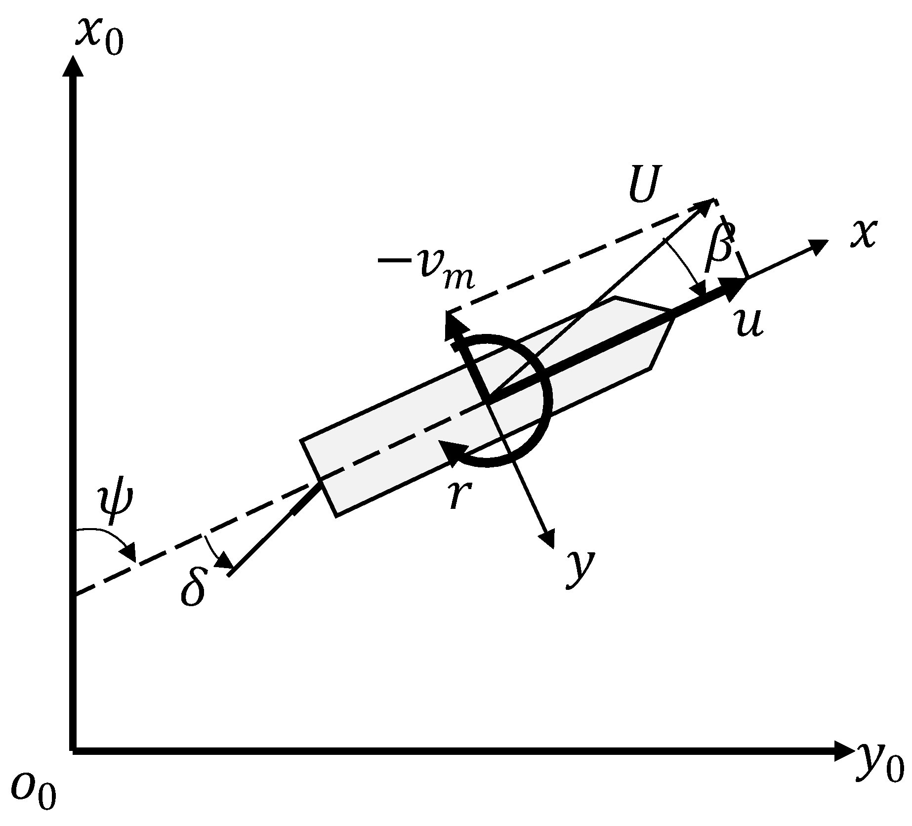
In the MMG model, the dynamics of the ship were defined according to the moving coordinate frame at the mid-ship location, as shown in
Figure 1.
The equation of motion of a ship is given in Equation (1), where
u is the surge speed,
vm is the sway speed,
r is the yaw rate,
U is the resultant speed,
β is the drift angle,
m is the mass of the ship,
mx,y are added mass components,
IzG is the inertia of the ship around the center of mass, and
Jz is an added inertia term. The acting forces were formulated component-wise and given on the right side of the equation. Indices of
H,
P,
R,
Wind,
Wave, and
Rotor correspond to forces related to hull hydrodynamic resistance and the propeller, rudder, hull–wind interaction, hull–wave interaction, and rotor sail, respectively. The formulation of forces related to all terms except rotor sail force generation were derived from previous studies [
29,
30]:
Unlike conventional ships, wind-assisted ships can prefer cruising where strong winds exist to harvest large amounts of energy. However, strong winds and waves generate large forces not only in the surge direction but also in the sway direction. In order to follow a given route in a given time, a PID controller was created to handle the rudder angle and propeller revolution.
The rotational speed of the rotor sails should be adjusted throughout the voyage to control the thrust and side forces generated by rotor sails. The rotational speed of rotor sails was defined using a dimensionless parameter, spin ratio (
SR). The spin ratio is the ratio of the tangential speed of the rotor sail, which is the multiplication of angular speed,
ω, and radius,
R, of the rotor sail, to apparent wind speed
VA, as given in Equation (2).
The generated force and required rotor sail power depend on the spin ratio,
SR, apparent wind speed,
VA, coefficients of lift, drag, and power (
cL,
cD, and
cP), and the projected area of the sail,
A. Apparent wind speed,
VA, is determined by true wind speed, true wind direction, ship speed,
u, and
vm, and heading angle,
ψ. Aerodynamic coefficients
cL,
cD, and
cP are defined based on aspect ratio,
AR, diameter ratio,
De/D, and spin ratio,
SR, of the rotor sail, as given in Equations (3)–(5).
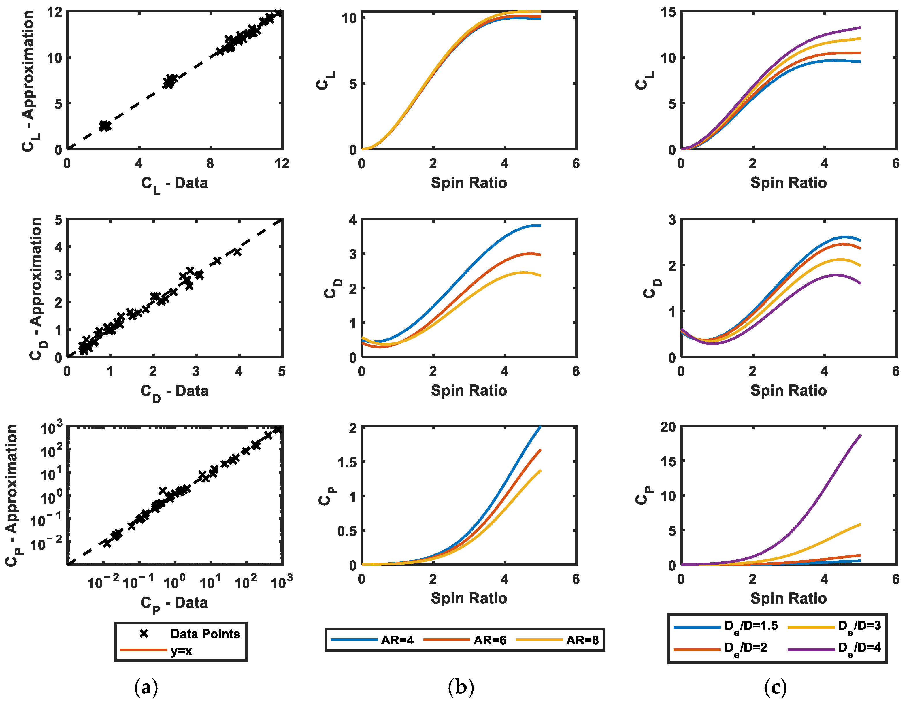
The relation between the design parameters and lift, drag, and power characteristics of the rotor sails was investigated via extensive CFD analyses by Kwon et al. [
22]. In the present study, the results obtained in the previous study [
22] were used. Then, regression models were built to investigate different designs and operational conditions of rotor sails as given in Equations (6)–(8). The coefficients of the regression models were determined by minimizing the error between CFD analysis data [
22] and the prediction models in Equations (6)–(8), as shown in
Table 2.
The performance of rotor sails is characterized by
cL,
cD, and
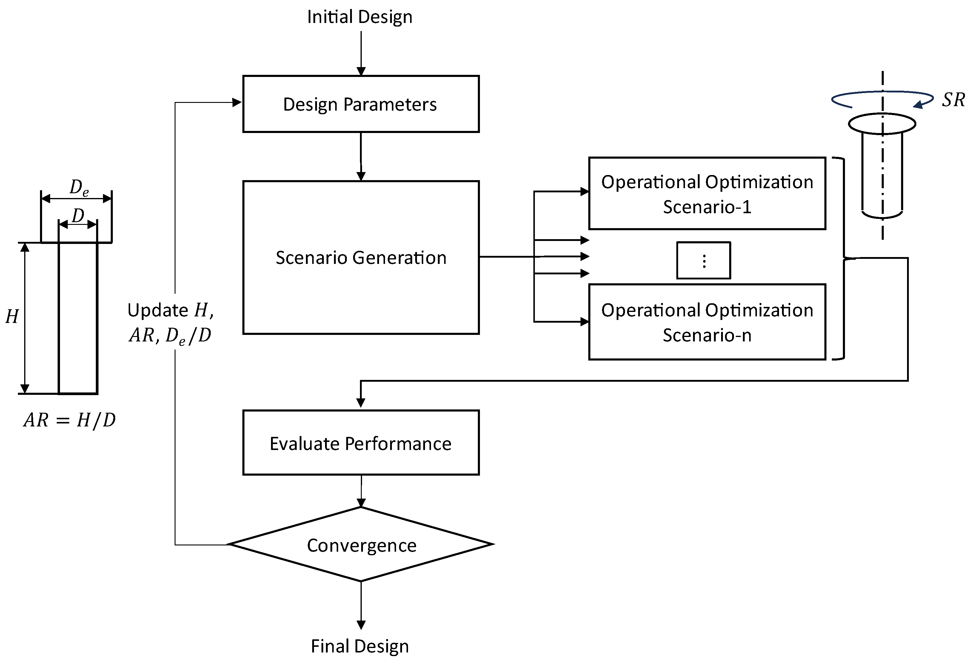
cP, and depends on both operational (spin ratio) and design parameters (height, aspect ratio, and diameter ratio) as they can be understood from the approximation formulas of lift, drag, and power coefficients. For this reason, the optimization problem was considered as a two-level problem. The design of the rotor sail was defined considering height,
H, aspect ratio,
AR = H/
D, and diameter ratio,
De/
D. Then, several scenarios with different wind speeds, wave heights, wave periods, and directions of wind/waves were considered. The operational parameter of the rotor sail, spin ratio (
SR), was optimized during the simulation to maximize the power reduction due to the rotor sail for given design parameters and each scenario in the operational optimization level. Then, the performance of the rotor sail was evaluated considering the percent reduction in average power for each scenario and the probability of each scenario. On the upper level of optimization, the design parameters of the rotor sail were determined to minimize the cost, considering different investment plans. The overall workflow of the optimization problem is given in
Figure 2.
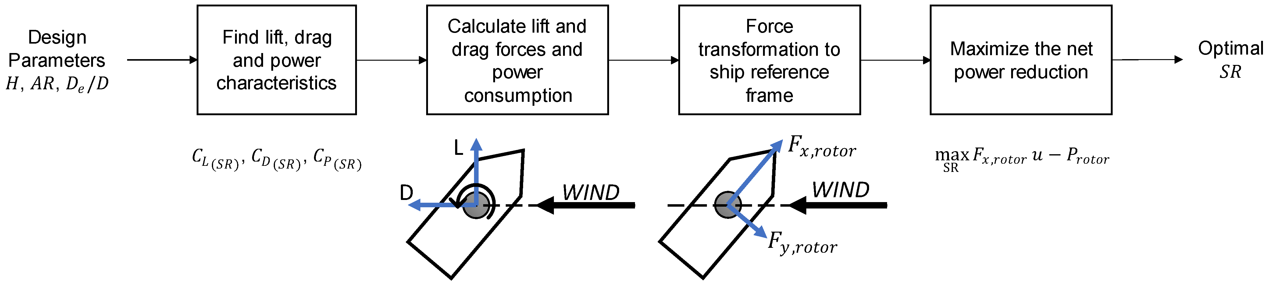
In the operational optimization level, the spin ratio of the rotor sail was found by maximizing the net power reduction at each time step for each scenario, as shown in
Figure 3. The lift, drag, and power characteristics of the rotor sails of the given design parameters
H,
AR, and
De/
D were obtained for varying spin ratios,
SRs, by using Equations (6)–(8). The range of spin ratio,
SR, was determined for each scenario between ±5, considering the clockwise and counterclockwise rotation of the rotor sail. Then, lift and drag forces were calculated within the range of the spin ratio and transformed to the ship reference frame to find thrust and side forces generated by the rotor sail. To determine the spin ratio during simulations, the net power reduction was calculated as the difference between the thrust power generated by the rotor sail and the required power of the rotor sail, as given in Equation (9). Then, the optimal spin ratio was found by maximizing the net power reduction at each time step for all scenarios.
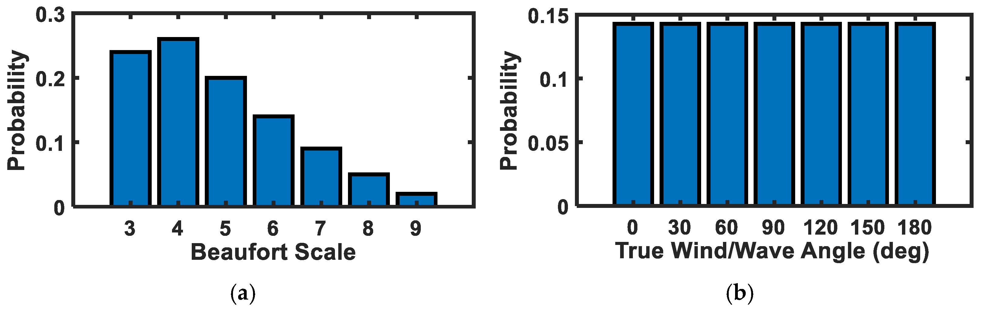
Since the performance of ships and sailing systems depends on environmental conditions, different wind and wave conditions were considered based on the Beaufort scale, which is an empirical measure of wind and wave conditions commonly used in maritime engineering, as given in
Table 3. In addition, true (global) wind/wave angle was considered within increments of 30 degrees in the range of 0–180 degrees to include all wind directions without significantly increasing the computational cost.
Depending on the route, ships are exposed to different environmental conditions. The probability of the Beaufort scale was assumed as shown in
Figure 4, and the probability of true wind/wave direction was assumed to be uniformly distributed. The distribution of the Beaufort scale was assumed considering Weibull distribution, which is commonly used for this purpose. Since wind can come from any direction, the distribution of true wind direction was assumed considering a uniform distribution.
After obtaining the optimal spin ratios of the given rotor sail for all scenarios with the probabilities of each scenario, the design optimization problem was defined. At the design optimization level, the performance of the rotor sail design was determined by considering the cost for the different investment periods. The design variables of the optimization problem are height,
H, aspect ratio,
AR, and diameter ratio,
De/
D. The lower and upper limits of the design variables were determined as 10 and 40 m for height, 4 and 8 for aspect ratio, and 1.5 and 8 for diameter ratio based on the limits considered by a previous study [
22] and existing rotor sails in the market.
Then, a MATLAB R2022b surrogate optimizer, “surrogateopt” [
31], was used to find the optimal rotor sail design by minimizing the objective function. The objective function was defined by considering the initial cost of rotor sails,
cinitial, and total energy consumption as given in Equation (10), where
p(i,j),
Pprop, and
Protor are probability, average propeller power (kW), and rotor sail power (kW) for a scenario having
ith Beaufort scale and
jth true wind/wave direction,
h is specific fuel consumption (0.160 kg/kWh),
cfuel is the price of fuel (0.6 USD/kg),
w is working rate (0.5), and
t is the interested time interval in hours.
Since increasing the area and volume of rotor sails produces larger thrust forces and requires larger operational power in general, the initial cost,
cinitial, was expected to increase. The initial cost of a rotor sail,
cinitial, was predicted based on the surface area, including lateral area,
Alateral, and top plate area,
Atop, as well as volume of the cylinder,
V, as given in Equation (11). The coefficients of
a and
b were assumed to be 2500 USD/m
2 and 800 USD/m
3, respectively.
3. Results
The aerodynamic performance of rotor sails was predicted based on the CFD analyses performed, and lift/drag forces and required torque of a rotor sail having a 9 m height with different aspect and diameter ratios were found for spin ratios between one and five by Kwon et al. [
22]. To generalize the results obtained by the previous study, lift, drag, and power coefficients were calculated as dimensionless aerodynamic parameters. In addition, it was assumed that the coefficients of drag, lift, and power were equal to 0.5, 0, and 0, respectively, for
SR = 0. Then, regression models of lift, drag, and power coefficients, which are given in Equations (6)–(8), were created; the parameters of the regression model are presented in
Table 2. The accuracy of the presented regression models and how aspect ratio, diameter ratio, and spin ratio affect lift, drag, and power coefficients are shown in
Figure 5. According to
Figure 5a, the approximation functions of the lift, drag, and power coefficients represent the behavior of the simulation data well. An increase in the aspect ratio increases the drag and power coefficients when the diameter ratio is fixed to two, as shown in
Figure 5b. When the diameter ratio is increased at the aspect ratio of eight, the lift coefficient increases and the drag coefficient decreases, as shown in
Figure 5c. However, more importantly, the power coefficient increases dramatically when the diameter ratio increases. Thus, rotor sails having larger endplate diameters require a significantly higher amount of power, which makes them less favorable.
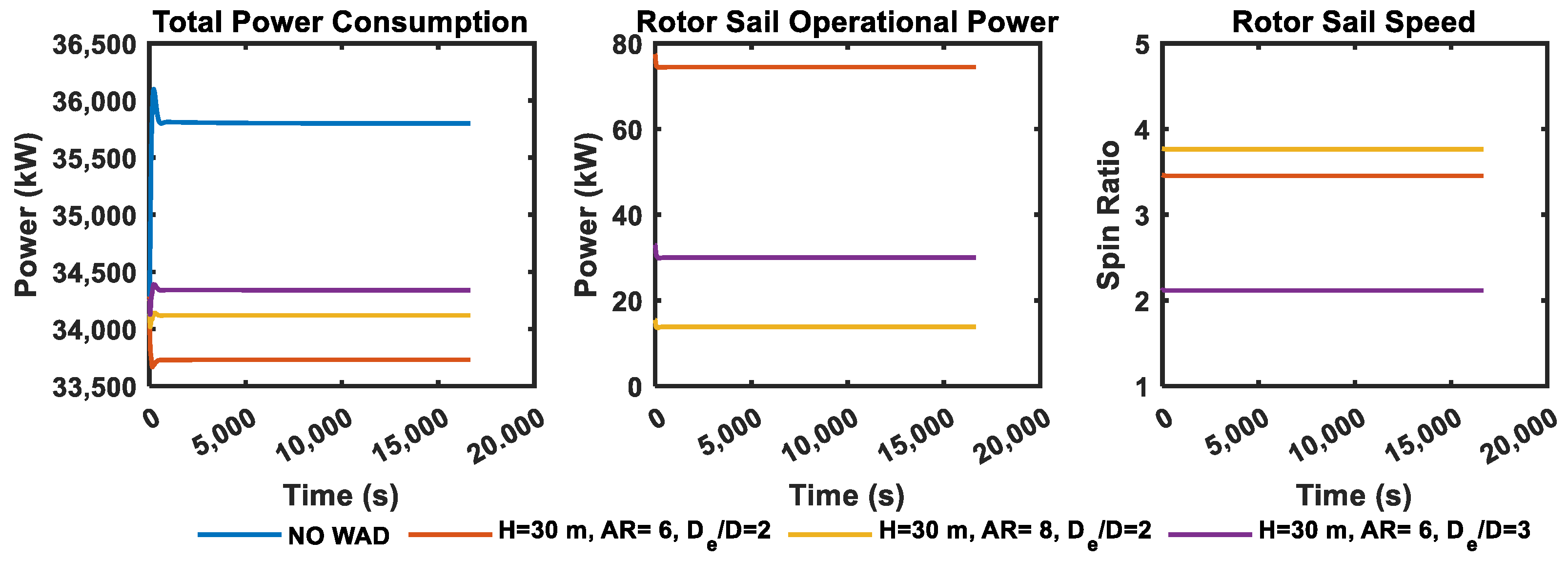
The system responses of wind-assisted ships having different rotor sail designs were obtained considering wind and waves of Beaufort scale 4 in the direction of 90 degrees, as shown in
Figure 6. It was revealed that changing the aspect ratio or diameter ratio affects the operational conditions of rotor sails. For example, the operational power of a rotor sail having an aspect ratio of six is larger than that of a rotor sail having an aspect ratio of eight, although it rotates at a lower spin ratio than rotor sails having an aspect ratio of eight. This is because rotor sails with a lower aspect ratio or larger diameter require larger operating torque, which increases the operational power. When the operation of rotor sails with smaller aspect ratios is optimized, there is a tendency to keep speed lower compared to rotor sails with a larger aspect ratio or smaller diameter. Due to the dependency of the optimal spin ratio and the rotor sail design, a two-level optimization method was considered. First, the spin ratio of the rotor sail was optimized for each environmental scenario given in
Table 3 and different true wind/wave angles between 0 and 180 degrees. Then, the objective function of the design optimization problem was evaluated, considering the average power for each scenario and corresponding probabilities given in
Figure 4.
Increasing CO
2 emissions and the introduction of new policies such as carbon taxes pushes businesses to seek solutions for existing ships. New technologies or methods have been proposed to reduce the CO
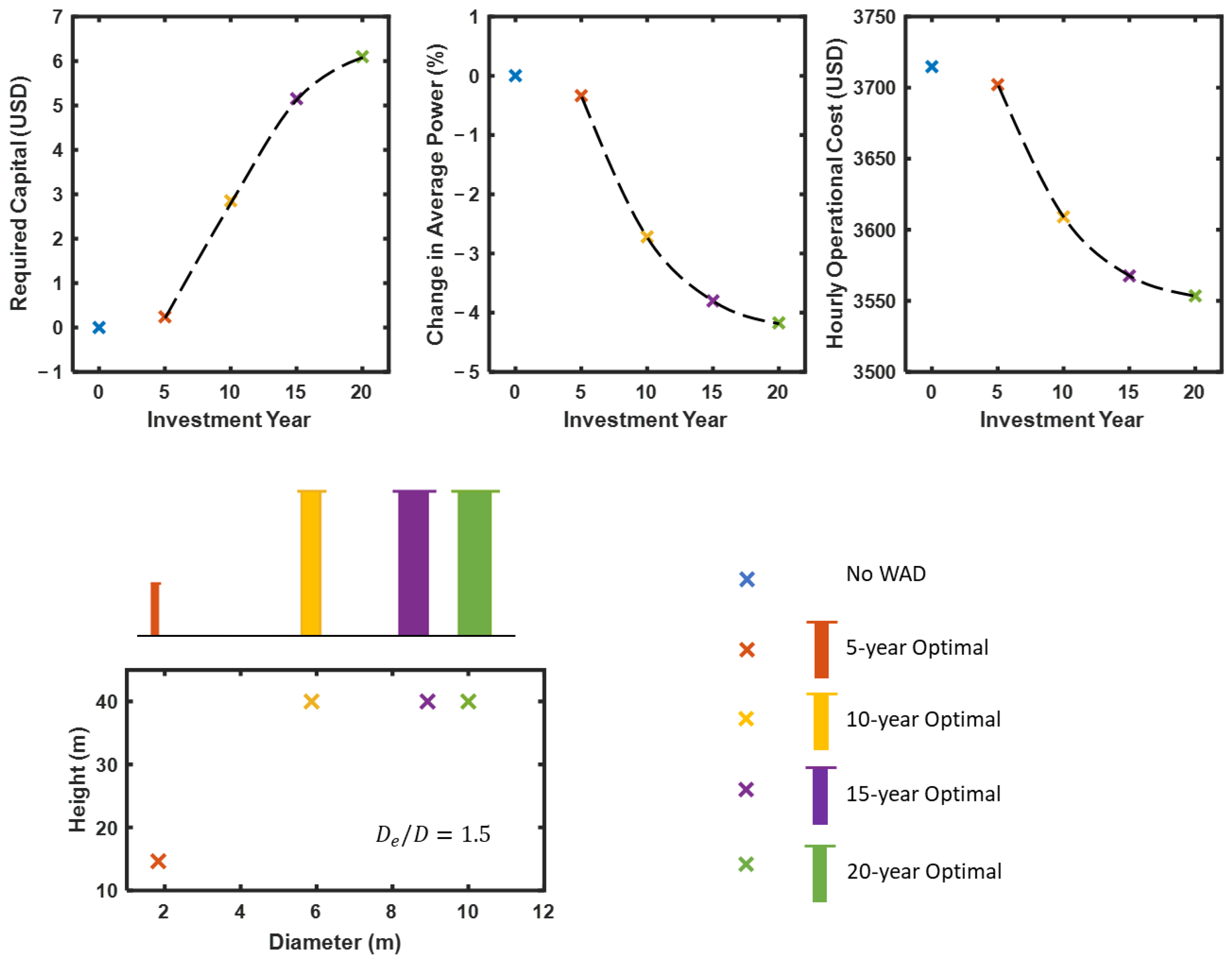
2 emissions of existing and new ships. Therefore, it is necessary to find a solution for different investment periods. Optimal designs that minimize the total cost for the investment periods of 5, 10, 15, and 20 years were found, as shown in
Figure 7. The optimal design for the 5-year investment is found to have quite a small size compared to the size of optimal designs for longer investment periods. When the investment period increases, optimal designs change by increasing the height and decreasing the aspect ratio. Although the ratio of end plate diameter and cylinder diameter,
De/
D, significantly affects the aerodynamic coefficients, it was found that all optimal designs have a
De/
D of 1.5, which is the lower bound. When the size of the optimal rotor sail increased together with the investment period, it was found that the required capital also increased and average power and operational cost decreased. A single rotor sail reached an approximately 4% reduction in average power for the cases of optimal design considering the 15-year and 20-year investment periods.
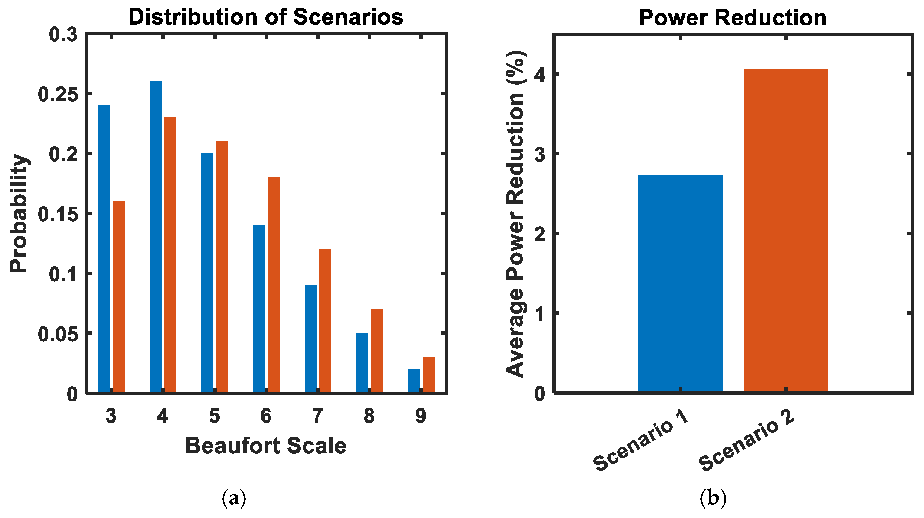
The optimal design of rotor sails also depends on the probability of different wind and wave conditions, as shown in Equation (10). In addition to the environmental conditions given in
Figure 4, a more severe environmental condition was also generated as given in
Figure 8a. When wind and wave conditions become more severe, the optimal design of rotor sails changes to a larger sail by decreasing the aspect ratio, in other words increasing the diameter of the cylinder, for the 10-year investment plan. The reduction in average power was increased to 4.06%, as shown in
Figure 8b.
4. Discussion
Rotor sails are one of the promising solutions to reducing the CO2 emissions of large ships by using available wind energy and generating additional thrust. Many studies have been previously conducted to predict how much of a reduction in average power and CO2 emissions can be achieved. Since there are many design alternatives, it is necessary to understand what kind of rotor sail design fits well and contributes to the reduction of CO2 emissions at the maximum level.
Wind-assisted ship propulsion and navigation are composed of several components that generate forces and interact with each other. It is necessary to build a holistic approach by considering hydrodynamic resistance, propeller characteristics, and rudder, wind, and wave interactions to understand the effect of sailing systems. For instance, forces in the forward and side directions are generated due to wave and wind interactions, as well as rotor sails. Therefore, it is necessary to control propeller revolution and rudder angle. Depending on the generated forces in the forward direction, the propeller revolution is adjusted to provide the necessary thrust at a given speed and the rudder angle is slightly changed to maintain the route due to side forces. In addition to environmental conditions, the design of rotor sails also affects system responses. When different sailing systems are implemented on a ship, the operational conditions of rotor sails are different to minimize the total energy consumed, as shown in
Figure 6.
The optimal operating condition of rotor sails depends on the design of the rotor sails, ship speed, and environmental conditions. When wind speed and direction change, the optimal spin ratio also changes. If a different rotor sail design was implemented on the ship, the optimal spin ratio for the same environment was also different, as shown in
Figure 6. In the proposed two-level optimization workflow, the spin ratio was optimized at each time step for each environmental scenario and the given design parameters, and the design parameters of rotor sails were optimized on the design level. Thus, the optimal rotor sail design that operates at the optimal spin ratio was found. The proposed approach allows us to consider many different environmental scenarios using fewer design variables.
A simple cost model was proposed to estimate how the initial cost of a rotor sail changes. Due to the lack of available data, it was considered that the initial cost depends on the surface area and the volume of a rotor sail, because the increase in surface area and volume increases material and manufacturing costs, and the cost of operating an engine will also increase to provide the demanded power. Then, the operational cost of the ship was predicted based on fuel consumption to provide the required amount of power for the propeller and sailing system. By minimizing the total cost, the most feasible design considering different investment periods can be obtained.
Optimal designs considering different investment periods showed a reduction in total cost compared to the ship without any wind assistive system, according to
Figure 7. It can be said that rotor sails provide not only environmental but also economic benefits after optimization. When the investment period increases, the design of rotor sails becomes taller and thicker by keeping the diameter ratio at 1.5. For shorter investment periods, the optimal design of the rotor sail was smaller and provided a small amount of reduction in power and operational cost. When the investment period increased, the height of the rotor sails increased first. Then, the aspect ratio was reduced, and the diameter of the rotor sail increased, because decreasing the aspect ratio of the rotor sails increased the drag and power coefficient, which requires larger operating engines and power. Although increasing the diameter ratio increases the lift coefficient significantly, the amount of increasing operational power makes rotor sails with a large diameter ratio inefficient.
Another important issue in obtaining better performance from rotor sails is to be exposed to suitable weather and sea conditions through route optimization. Previous studies have shown that route optimization can contribute to a reduction in energy consumption [
10,
11]. When environmental conditions become more severe, the effect of rotor sails on energy consumption also changes. For this purpose, the optimal shape of the rotor sail was found for a more severe environment by changing the distribution of the scenarios. The optimal shape of the rotor sail for a more severe environment had a larger diameter because the potential of generating thrust force was higher and a rotor sail with a larger diameter reduced total power, even though it increased the initial cost of the rotor sail. As shown in
Figure 8, the rotor sail optimized for a more severe environment provided approximately 48% better performance by increasing the average power reduction from 2.74% to 4.06%.
In the present study, it was found that optimal designs considering a single rotor sail can achieve approximately 4% reduction in average power. However, it is not enough to achieve net-zero emissions by 2050, which was the aim of IMO. In addition to optimizing the design and improving the performance of rotor sails, other actions are also necessary. When the number of rotor sails increases, the reduction in energy consumption and CO
2 emissions can be increased. Route optimization is one of the solutions to reducing energy consumption by traveling where strong winds exist in desirable directions. Reducing ship speed is another way of reducing energy consumption [
7,
8,
9]. Additionally, changing the size and shape of the hull can contribute to a reduction in energy consumption.
The initial cost of rotor sails was assumed to change depending on the volume of the cylindrical shape and surface area, including the end plate, of rotor sails, since the exact pricing of rotor sails depending on the shape is confidential and difficult to obtain. When the investment was evaluated, the fuel price was assumed to be constant. Together with an increase in fuel prices, incentives for clean energy and the introduction of a carbon tax will make rotor sails more economically feasible in the future. In future studies, the economic model can be improved and applied to multiple rotor sail solutions to find out what kind of rotor sails are best for different target ships and different routes by updating the ship and environmental parameters.
There are several limitations to the model. When rotor sails are placed on ships, a large rolling moment is generated due to the large force generation capacity and height of the sail. In addition, the center of mass of the ship is shifted upward due to the weight of the rotor sail system, which can reduce ship stability. When the number of sails increases, the rolling moment generated by the sails and the change in the position of center of mass increases. This should be further studied to analyze safety and stability, especially for ships with many sails. Increasing the number of sails may significantly reduce the amount of cargo due to the additional weight created by rotor sails. In the present study, rolling angle, variation of center of mass, and reduction in cargo size were not considered due to negligible effects when a single sail was used.
When rotor sails generate thrust force, the required thrust by the propeller reduces and propeller revolution is decreased by a speed controller. Engine efficiency changes depending on propeller revolution. The variation in propeller revolution was not significant enough to affect the efficiency of the engine. Therefore, the specific fuel consumption of the engine was assumed as constant. However, the variation in propeller revolution increases when the number of sails increases, and the variation in specific fuel consumption should be considered when implementing multiple rotor sails.


