Article

Vibration-Resistant Performance Study of a Novel Floating Wind Turbine with Double-Rope Mooring System and Stroke-Limited TMD

1
Key Laboratory of Wind and Bridge Engineering of Hunan Province, College of Civil Engineering, Hunan University, Changsha 410082, China
2
Research Institute of Hunan University in Chongqing, Chongqing 401151, China
*
Author to whom correspondence should be addressed.
J. Mar. Sci. Eng. 2023, 11(1), 58; https://doi.org/10.3390/jmse11010058
Submission received: 12 November 2022 / Revised: 17 December 2022 / Accepted: 20 December 2022 / Published: 1 January 2023
(This article belongs to the Special Issue Offshore Wind Turbine Foundations)

Abstract

:
Floating offshore wind turbines (FOWTs) are generally located in the harsh deep-sea environment and are highly susceptible to extreme loads. In order to ensure the normal operation of FOWTs, this article takes the semi-submersible FOWT as an example, proposes a new double-rope mooring system, and studies the dynamic performance of the FOWT with the double-rope mooring system and its effectiveness in reducing the dynamic response of the wind turbine. At the same time, the tuned mass damper (TMD) is installed in the nacelle of the wind turbine, and the TMD parameters are optimized considering the space limitation of the nacelle by limiting the TMD’s stroke, which further reduces the dynamic response of the FOWT and improves its stability. Numerical simulation and analytical studies show that the new double-rope mooring system can reduce the dynamic response of the wind turbine to a greater extent than the traditional single-rope mooring system. Considering the stroke restriction, the control performance of TMD will be slightly weakened, but it is more in line with the actual engineering requirements. Compared with the original FOWT, the proposed new type of FOWT has better dynamic stability and has the prospect of extending to real engineering applications.

1. Introduction

In recent years, with the gradual imbalance of the supply and demand of traditional energy and the increasing global warming effects, many countries have focused on renewable energy and the increased development and utilization of renewable energy technologies. For example, China’s “dual carbon” strategy implies the gradual withdrawal of traditional energy systems and their replacement with new energy systems. Compared with traditional fossil energy, wind energy, as one of the renewable energies with the most promising development and utilization, has the advantages of sustainability, pollution-free, and large storage capacity.
According to relevant statistics, the current wind power generation is mainly based on onshore wind turbines [1]. However, with the expansion of the wind power industry, onshore wind farms have problems such as a shortage of available land resources, fewer wind resources, and they are easily disturbed by weather conditions. In contrast, the power generation efficiency of offshore wind farms, especially those located in the deep sea, is 20–40% higher than that of onshore wind farms. Offshore wind turbines have the advantages of not occupying land resources, abundant wind resources, and stable power generation efficiency [2]. Because of the high cost and technical difficulty of building fixed-bottom wind turbines in the deep ocean, floating offshore wind turbines (FOWTs) are increasing year by year. More and more countries take FOWT technology to be the focus of future wind energy technology development [3].
The FOWTs are located in the ocean environment, and they are often affected by wind, waves, current, and other external loads. Due to these environmental loads, the reliability of FOWTs is often threatened. The working sites of FOWTs are located in the deep sea, and maintenance is difficult and expensive. Therefore, controlling the FOWT vibration under harsh conditions and improving the vibration resistance of the wind turbine are very important research topics [4,5,6,7].
One way to reduce the vibration amplitude of the floating wind turbine platform is to optimize the mooring system [4,5,8,
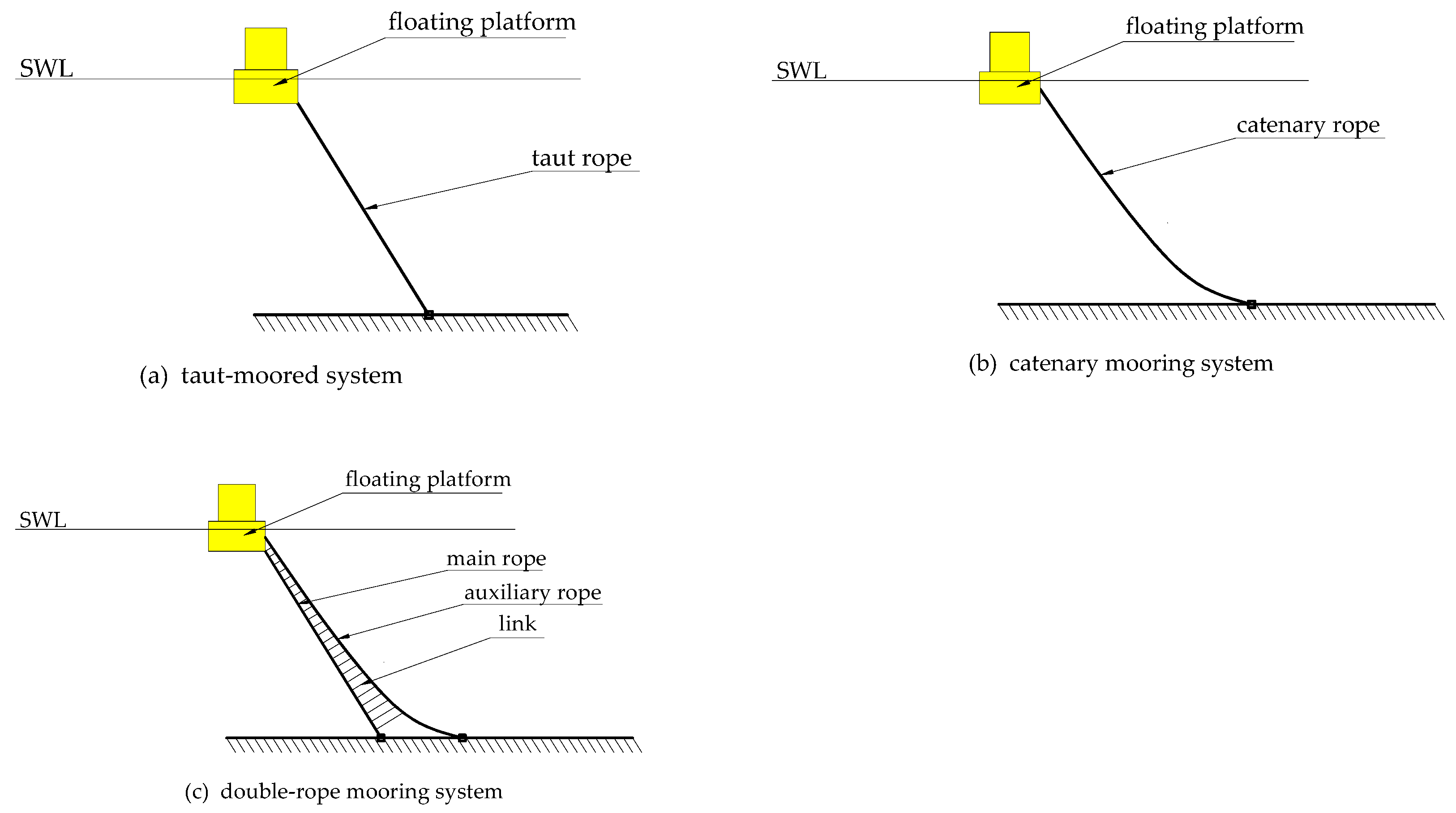
9]. Currently, most of the floating wind turbine mooring systems adopt a taut leg mooring system or catenary mooring system. The taut leg mooring system has good vibration reduction performance, but its fatigue resistance is poor because the mooring line is under tension at all times [10]. On the contrary, the catenary mooring system has good fatigue resistance but poor vibration reduction performance because the line is sagging, and it provides less tensile stiffness. In order to meet both vibration reduction performance and fatigue resistance performance, the mooring system needs to be optimized by changing the form of the mooring line and the line material or the layout of the mooring lines. Because the mooring system has an important impact on the dynamic characteristics, stability performance, and economic benefit of the FOWT, more and more studies focus on the mooring system of the floating wind turbine. Liu et al. proposed a new type of three-bifurcated mooring system [4]. Compared with the original mooring system with three mooring lines, the new mooring system has two branch mooring lines for each original mooring line, which can obtain greater overturning and torsional stiffness. The designed mooring system can reduce the wind turbine surge motion by 37.15% and 54.5% at most and the yaw motion by 30.1% and 40% at most under regular and irregular waves, respectively. Liu et al. also designed a mooring system with six mooring lines, which were divided into three groups [5]. Two mooring lines in the same group were connected to the same fairlead, and the design also achieved good vibration reduction performance. Liu et al. proposed adding mass blocks to the mooring lines to reduce the surge motion [8]. The results show that the wave-induced response can be effectively reduced by adding only one-tenth of the mass to the mooring line. Yuan et al. proposed a novel mooring system that can resist both pitch and horizontal motion by dividing the fairleads into two groups at different depths [9]. The results show that the innovative mooring system can significantly reduce the pitch and surge motions of the FOWT. Therefore, the innovative design and parameter optimization of the mooring system is an effective way to reduce FOWT vibration.
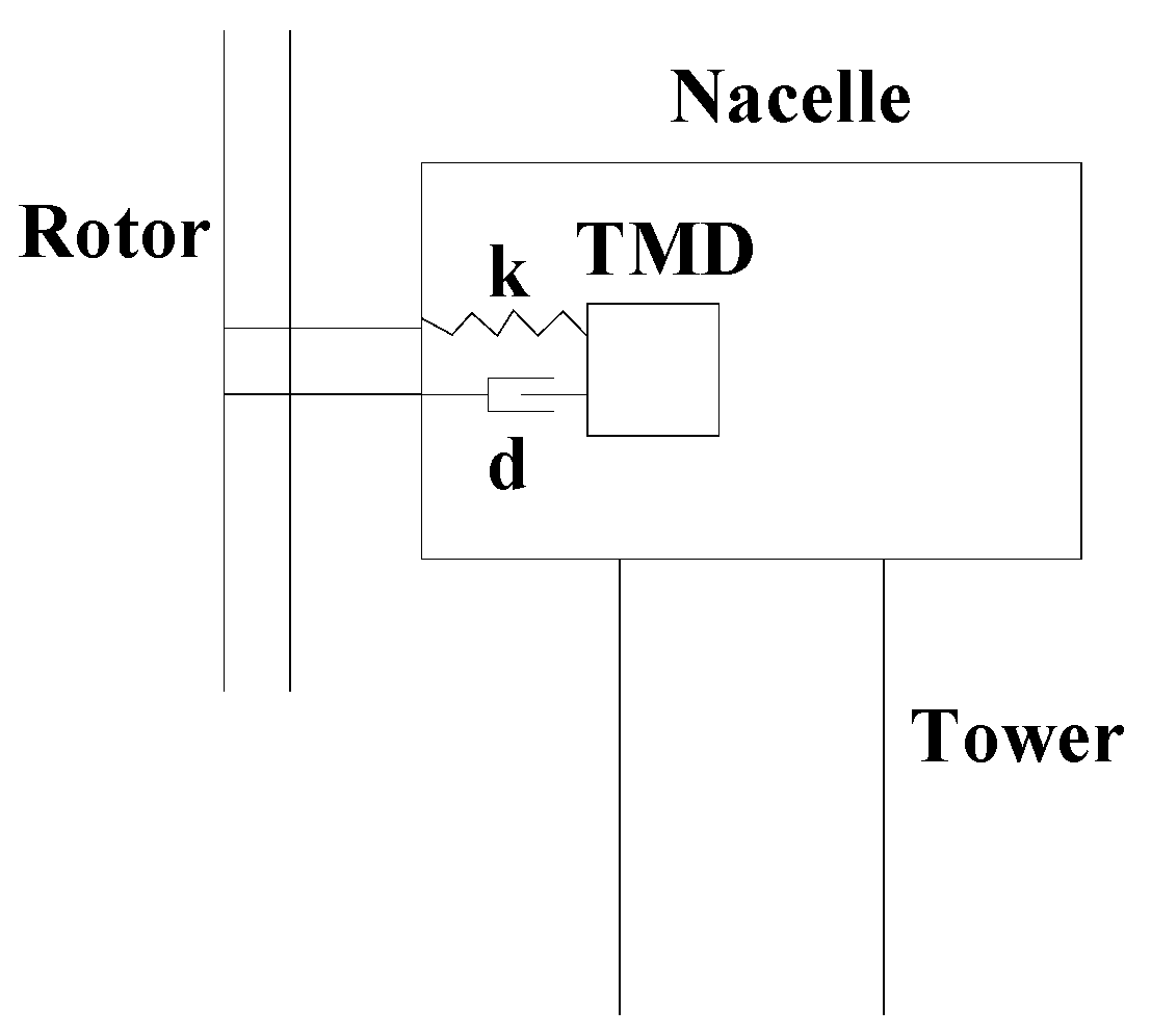
Another method to reduce the vibration amplitude of the floating wind turbine is to install structural control devices, such as a tuned mass damper (TMD) and tuned liquid column dampers (TLCD). The control objects include blades, a nacelle, a tower, and a floating platform. Structural control systems have been widely used in large structures such as buildings and bridges and have achieved good damping effects. Due to the floating characteristics of the FOWT, it is difficult to realize the direct damper connection between the fixed point of the seabed and the platform, so the vibration reduction can only be achieved by ungrounded vibration absorber devices, such as the tuned mass damper (TMD). The structural vibration control system reduces the influence of external loads by reducing the vibration amplitude of the wind turbine structure, which greatly improves the reliability of the FOWTs. Many scholars have studied the application of TMDs in FOWT vibration control and have achieved good vibration reduction effects. Dinh and Basu studied the application of single and multiple TMDs in the passive vibration control of spar-type floating wind turbines [11]. In the controlled model, several horizontal sets of TMDs were placed in the spar. It has been shown that a single TMD can reduce nacelle swag displacement and spar roll by up to 40% and multiple TMDS by 50%. Li et al. studied the use of TMD in the nacelle/tower for the passive vibration control of a semi-submersible offshore wind turbine [12]. The results show that TMD reduces structural vibration and thus extends the service life of floating wind turbines. Han et al. conducted the design optimization of multiple TMDs for semi-submersible floating wind turbines [13]. Jahangiri and Sun proposed a three-dimensional pendulum TMD and dual linear pounding TMDs to mitigate the three-dimensional vibrations of a spar-type FOWT under wind and wave loadings [7]. In addition to conventional TMDs, there are some special types of TMDs, such as nonlinear TMD [14], electromagnetic shunt TMD [15], and TMD with inerters [16,17], etc. These additional control measures all show better control performance. In addition, tuned liquid column dampers (TLCDs) are often used for vibration control in FOWTs. A well-designed TLCD can effectively reduce the tower side–side vibration as well as the spar roll motion [18]. Although a well-designed TMD has been proven to have a good effect on FOWT vibration control, previous studies seldom consider that the actual travel of TMD is greatly restricted due to the limitation of installation space, which means that the stroke of TMD is limited.
Although previous researchers have conducted a lot of studies on the vibration mitigation of FOWTs, the results still have room for further improvement. First, the mooring system needs to be further innovated to meet the requirements of vibration reduction and fatigue resistance. Second, the optimal design of vibration reduction devices such as TMD on FOWTs must consider the limitation of space in order to be more realistic. To consider these two aspects, this paper has two major contributions: one is the innovation of the mooring system, the other is the consideration of the stroke limit of TMD for vibration control. Taking a 5 MW semi-submersible offshore wind turbine as the research object, this paper proposes a new double-rope mooring system to improve its performance of vibration reduction and fatigue resistance, which aims at solving the shortcomings of a single-rope system in these two aspects. Additionally, when optimizing the parameters of the TMD installed in the nacelle, space constraints are taken into account by limiting the stroke of the TMD. Through theoretical analysis, numerical simulation, and parameter analysis, the vibration-resistant performance of the proposed novel FOWT was investigated. Under different working conditions, various vibration reduction schemes were simulated and analyzed to compare their vibration reduction effects on FOWT.
The structure of the rest of this paper is as follows: 
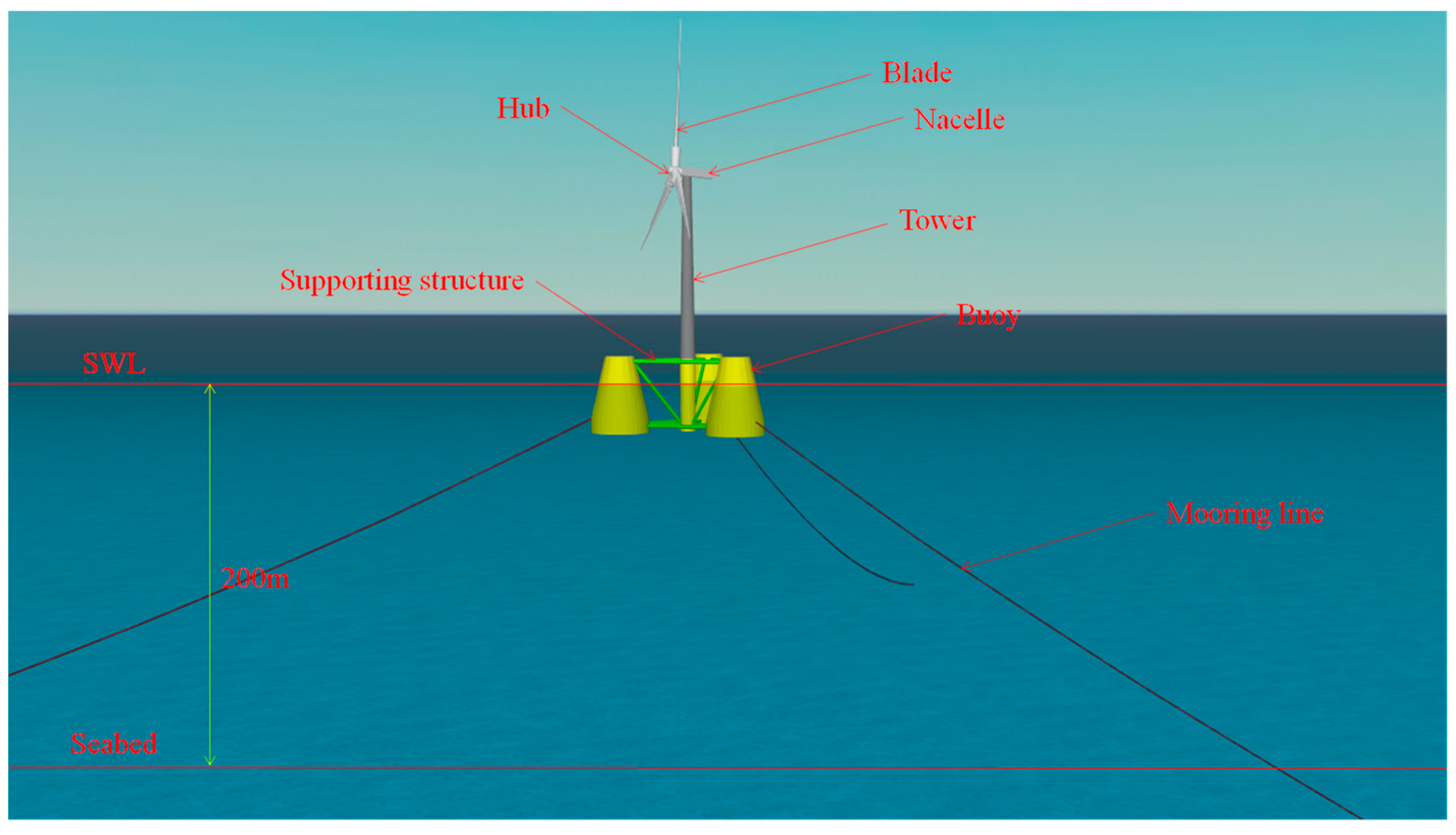
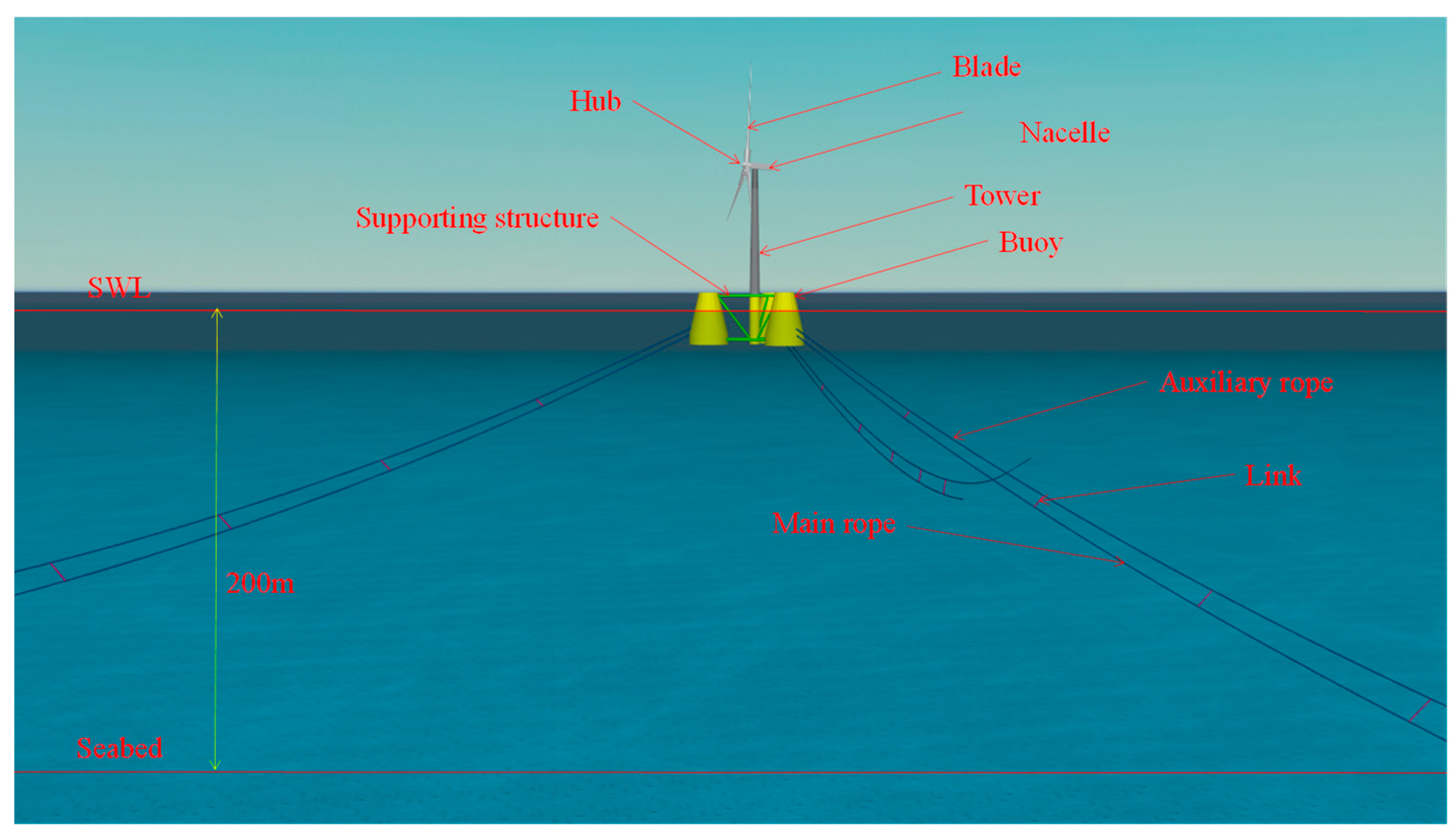
Section 2 mainly introduces the composition and modeling of the floating offshore wind turbines, including the traditional single-rope mooring system and the new double-rope mooring system proposed in this paper. Section 3 mainly introduces the dynamic characteristics of the two mooring systems and their dynamic responses in the normal operation state and the storm self-survival state and conducts parameter analysis of the double-rope mooring system. 
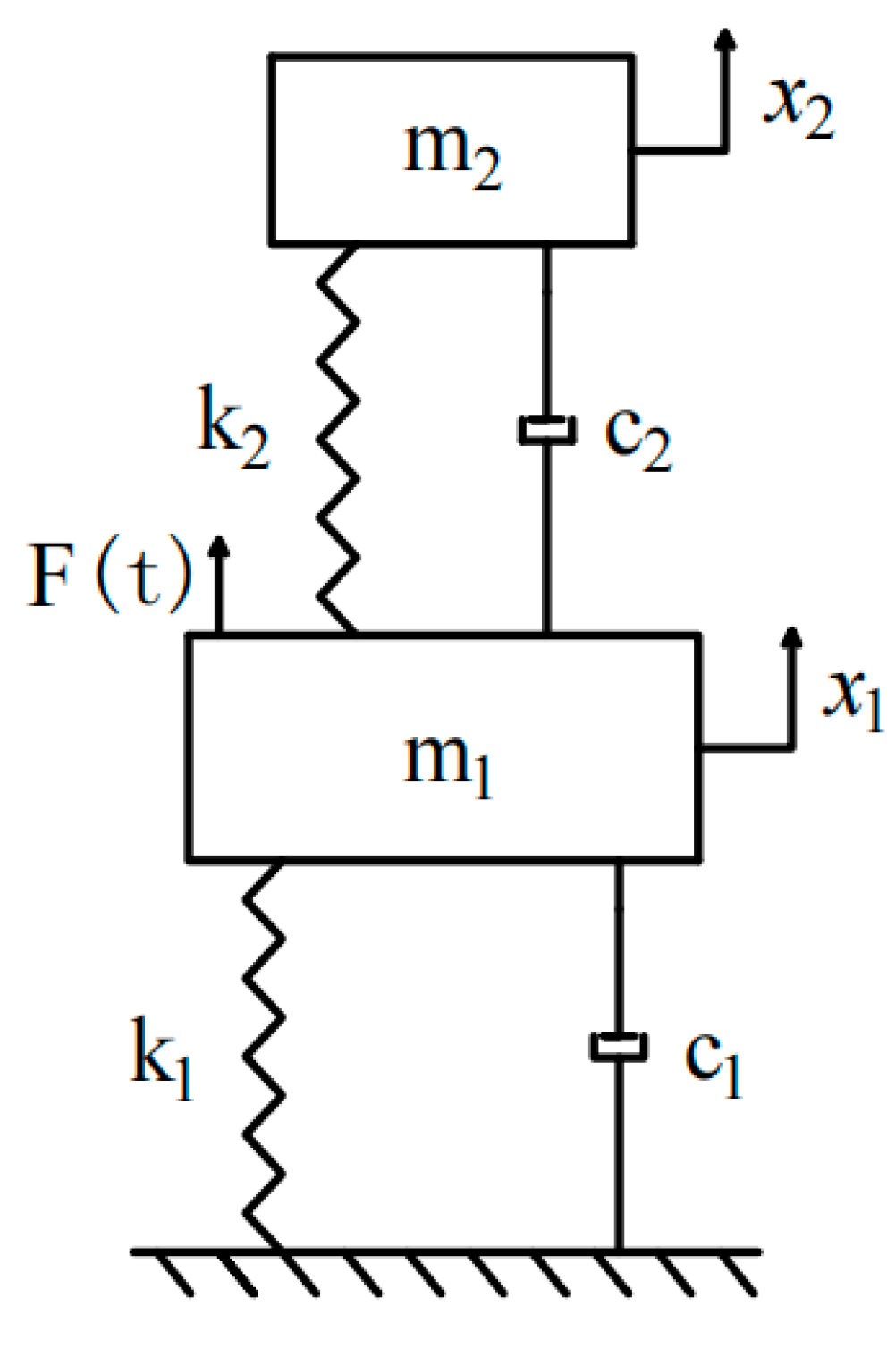
Section 4 mainly introduces the control theory of floating wind turbines based on TMD, the parameter optimization method considering TMD’s stroke limitation, and its influence on vibration reduction performance. Section 5 summarizes the whole article.

2. Composition and Modeling of Floating Wind Turbines

2.1. Composition and Moldeing of Original FOWT

2.1.1. Basic Parameters of the Semi-Submersible FOWT

This study mainly focused on the OC4-DeepCwind three-buoy semi-submersible wind turbine [19]. The modeling and simulation software that we used was OrcaFlex, which is a package for the dynamic analysis of offshore marine systems. The overall modeling can be divided into four parts: the wind-driven generator, tower, semi-submersible platform, and mooring system. The wind-driven generator set includes the blades, hub, and nacelle. The tower is usually a cylindrical hollow steel tower. The semi-submersible platform comprises a number of buoys and a supporting structure connecting them. The mooring system connects the floating platform to the seabed and plays a role in fixing and vibration control. It is generally composed of several mooring lines.
The wind-driven generator of the turbine is the 5 MW baseline wind turbine published by NREL [20], and the semi-submersible platform is the OC4-DeepCwind three-buoy structure [21]. The mooring system consists of three catenary ropes. The original floating wind turbine is shown in Figure 1; the calm sea level and the depth of the sea are presented in this figure as well. The depth of the sea at the turbine installation site is 200 m.
The wind turbine cut-in wind speed is 3 m/s. When the wind speed at the hub of the wind turbine reaches this value, the wind turbine starts to operate. The rated wind speed of the wind turbine is 11.4 m/s. When the wind speed at the hub of the wind turbine reaches this value, the wind turbine reaches its maximum power generation. The cut-off wind speed of the wind turbine is 25 m/s. When the wind speed at the hub of the wind turbine reaches this value, the wind turbine stops working and enters the storm self-storage state. The tower is a hollow steel column structure; the tower’s top outer diameter is 3.87 m, and the bottom outer diameter is 6.5 m. The semi-submersible platform is a three-buoy structure, the main body of which includes: a middle column, buoys, transverse braces, oblique braces, and a water-entrapment plate. Around the platform, there are three mooring lines tied to the surrounding walls of the buoys. The basic parameters of the original floating wind turbine are shown in Table 1, Table 2, and Table 3, respectively. These data can be found in the published literature [20,21], so they are not described in detail here. Interested readers should refer to the literature for more details.

2.1.2. Environmental Parameter

In this study, for the environmental parameters, both the wind load and wave load were considered. According to the working conditions of the floating wind turbine, the design conditions were defined as the normal operating condition and the storm self-survival condition. The normal operating condition was selected as a 10-year recurrence period, and the other was selected as a 50-year recurrence period.
In this study, the sea condition adopted was a certain sea area in the South China Sea; that is, the studied FOWT was assumed to be located in a certain sea area in the South China Sea [22]. For the normal operating condition, the average value of wind and wave in the South China Sea over the most recent ten years was taken. The wind type of the NPD Spectrum was adopted [23]. Table 4 shows the specific parameters of the NPD Spectrum. The wave type of the Jonswap Spectrum was adopted [24], which is a modification of the PM spectrum of the developing sea state in the case of limited data acquisition. Table 5 provides the specific parameters of the Jonswap spectrum.
For the storm self-survival condition, the extreme value of wind and waves in the South China Sea over the most recent 50 years was taken. The wind spectrum type and the wave spectrum type were consistent with those in the normal operating condition. Table 6 provides the specific parameters of the NPD spectrum in storm self-survival conditions. Table 7 provides the specific parameters of the Jonswap spectrum in storm self-survival conditions.

2.2. Composition and Modeling of New Floating Wind Turbine

2.2.1. FOWT Modeling Method

The simulation software used in this paper is OrcaFlex. The modeling sequence is roughly divided into four parts: the upper generator set, the middle tower, the lower semi-submersible platform, and the bottom mooring system. The upper generator set is divided into the blades, hub, and nacelle, wherein the blades and hub are modeled by the turbine element, and the nacelle of the wind turbine is modeled by the 6D bouys element. The line element is used for modeling the tower in the middle. The vessel element is used to model the lower semi-submersible platform, and the Morison element is used to model the supporting structure between the buoys. Mooring ropes are modeled using the lines element. In addition, the double-rope mooring system and TMD are included, and their modeling will be discussed in detail later.

2.2.2. Double-Rope Mooring System

As mentioned before, the single-rope mooring system is either where the taut rope is in a tensioned state or the catenary rope is in a sagging state, both of which have certain disadvantages. The taut leg mooring system has better vibration resistance but a poorer fatigue performance. The fatigue performance of the catenary mooring system increases, but the vibration resistance becomes worse. In order to solve the above contradiction, a novel double-rope mooring system is proposed in this study. The schematic diagrams of the taut-moored system, catenary mooring system, and double-rope mooring system are shown in Figure 2. The double-rope mooring system includes the main rope, the auxiliary rope, the links, and the submarine anchorage devices. The main rope is in a straight-line state with minimal sag and is connected between the platform and the anchorage device. The auxiliary rope is installed directly above the main rope, which has a large sag similar to the catenary and is connected between the platform and the anchoring device. The main rope and the auxiliary rope are connected by several links which are perpendicular to the main rope.
The double-rope mooring system can reduce the vibration of the floating platform and improve the fatigue resistance of the whole mooring system by combining the main rope and the auxiliary rope together. The auxiliary rope shape of the new double-rope mooring system is designed as a catenary with a large sag, and the fatigue resistance of the whole double-rope mooring system is improved while the main rope is pulled into an approximately straight line by the links. In this double-rope mooring system, the axial stiffness of the main rope is large, and the sag effect of the main rope is avoided. When the floating wind turbine is subjected to large external loads, the vibration response of the wind turbine is reduced through the restoring force generated by the main rope.
The main rope and auxiliary rope are modeled by the line’s element, and the links between them are simulated by the links element. Through the establishment of the main rope, the auxiliary rope, and the links, the whole model of the floating wind turbine with a double-rope mooring system based on the semi-submersible platform can be obtained, as shown in Figure 3.

2.2.3. Attached Tuned Mass Damper

In this study, the control objective is the along-wind vibration of the semi-submersible wind turbine, including the tower tip displacement of the floating wind turbine and the surge and pitch of the floating platform. As for the installation position of TMD, considering the spatial limitation, the vibration reduction effect, and the economy, TMD is installed in the nacelle on the top of the tower [25]. The schematic diagram of the floating wind turbine equipped with TMD is shown in Figure 4. TMD consists of the mass, spring, and damper, among which the mass is modeled by the 6D bouys element, and the spring and damper are modeled by the links element, and the model in OrcaFlex of the floating wind turbine equipped with TMD is shown in Figure 5.

3. Dynamic Characteristics of Floating Wind Turbines

3.1. Modal Analysis of Floating Wind Turbine

3.1.1. Modal Features of Original Floating Wind Turbine

The modal features of the original floating wind turbine can be obtained by modal analysis in OrcaFlex. The first 20 modes of the original floating wind turbine are shown in Table 8. It can be seen from their modal frequencies that FOWT’s natural frequencies are all very low; the lowest is the surge mode, followed by the sway, yaw, pitch, roll, and heave mode.

3.1.2. Modal Features of New Floating Wind Turbine

The modal analysis of the new floating wind turbine with a double-rope mooring system was carried out, and the parameters set were consistent with the original floating wind turbine. Table 9 shows the first 20 modes of the new floating wind turbine. It can be seen from the table that the introduction of double-rope mooring increases the natural frequencies of the wind turbine. Except for the Heave mode, the other five modal frequencies of the surge, sway, yaw, pitch, and roll increase very obviously, and the order of the modes changed to a certain extent, with the yaw mode appearing first instead of the surge mode in the original one.

3.2. Dynamic Response of Floating Wind Turbine with Different Mooring Systems

3.2.1. Dynamic Response of Floating Wind Turbine Platform

The environmental parameters of the floating wind turbine with the new double-rope mooring system were set in accordance with those of the original one, and dynamic responses of the normal operating condition and storm self-survival condition were analyzed in the time domain and frequency domain, respectively. The vibration reduction effect of the new double-rope mooring system was evaluated by comparing the dynamic response with those of the original wind turbine.
Under normal operating conditions, as wind and waves attack the structure in the upwind mode, only the vibration responses in the direction of the surge, pitch, and heave need to be considered. Figure 6 shows the comparison of vibration responses of two types of mooring systems in the direction of the surge, pitch, and heave. It can be seen from the spectrum diagram that, compared with the original mooring system, the frequency of surge in the new mooring system increases, the peak value decreases significantly, the first frequency of heave disappears, and the pitch frequency increases slightly, but the peak value decreases. This indicates that the new mooring improves the part of the stiffness and reduces the dynamic response.
In order to quantitatively express the vibration reduction effect of the double-rope mooring system compared with the original single-rope mooring system under normal operating conditions, Table 10 compares the root mean square (RMS) of the surge, heave, and pitch. It can be seen from the table that, compared with the original floating wind turbine, the new double-rope mooring system has improved the vibration resistance of the wind turbine in aspects of surge, heave, and pitch. In terms of surge and pitch, the response amplitude decreases by 60.3% and 12.9%, respectively. In the heave, the response amplitude of the wind turbine decreases by 5%, which is not obvious as surge and pitch. In general, under normal operating conditions, the new double-rope mooring system plays an effective role in mitigating the dynamic response of the wind turbine structure.
Figure 7 shows the comparison of vibration responses of two types of mooring systems in the direction of the surge, pitch, and heave under storm self-survival conditions. As can be seen from the spectrum comparison diagram, compared with the original mooring system, the frequency of the surge in the new mooring system increases, and the peak value decreases significantly; the first frequency of heave disappears, and the peak values of other frequencies decrease slightly. The frequencies of pitch also partially disappear, and the peak values of other frequencies decrease.
Table 11 compares the RMS values of the surge, heave, and pitch under storm self-survival conditions. It can be seen from Table 11 that, compared with the original floating wind turbine, the new double-rope mooring system improved the vibration resistance of the wind turbine in the three aspects of surge, heave, and pitch. In terms of surge and pitch, the response amplitude decreased by 35.4% and 14%, respectively. For the heave, the response amplitude of the wind turbine decreased by 3.6%, which is not as obvious compared to surge and pitch. In general, under storm self-survival conditions, the new double-rope mooring system plays an effective role in reducing the dynamic response of the wind turbine structure.

3.2.2. Analysis of Mooring Rope Force

During the operation of floating wind turbines, the change in the mooring rope force affects the anti-fatigue performance of the mooring rope. In order to verify the advantages of the main rope of the new double-rope mooring system in fatigue resistance compared with the single-rope mooring system, a simulation was conducted in the same environment to analyze the rope forces.
In the case of normal operating conditions, the main rope force on the windward side was studied. It was found that the RMS of the rope force for the original single-rope mooring was 75.24 kN, and the RMS of the main rope force for the new double-rope mooring was 68.88 kN. Compared with the original single-rope mooring system, the RMS of the mooring forces of the new double-rope mooring system decreased by 8.45%. It can be concluded that the main rope of the new double-rope mooring system has stronger anti-fatigue abilities under normal operating conditions, considering the actual load of the wind and waves.
In the case of storm self-survival conditions, the main rope force on the windward side was studied as well. It was found that the RMS of the main rope force for the original single-rope mooring was 552.75 kN, and the RMS of the main rope force for the new double-rope mooring was 445.35 kN. Compared with the original single-rope mooring system, the RMS for the rope force of the new double-rope mooring system decreased by 19.4%. It can be concluded that the main rope of the new double-rope mooring system has stronger anti-fatigue abilities under storm self-survival conditions, considering the actual load of the wind and waves.

3.3. Parametric Analysis of Double-Rope Mooring System

3.3.1. Influence of Pretension of Main Rope

In the mooring system, restoring the stiffness of the rope is nonlinear, and its initial pretension is needed to determine its initial restoring stiffness. In the original mooring system, the initial pretension of the rope will affect the response of the semi-submersible platform and the tension force of the mooring rope. The main rope in the double-rope mooring system provides the main restoring force for the vibration reduction of the semi-submersible platform. The change in its pretension is related to the vibration of the semi-submersible platform and the rope force.
In normal operating conditions, the initial pretension of the main rope is taken as follows: 2050 kN, 2150 kN, 2250 kN, and 2350 kN. In the storm self-survival condition, the following values of initial pretension are taken, respectively: 2650 kN, 2750 kN, 2850 kN, and 2950 kN.
Under normal operating conditions, the adjusted models of different rope pretensions are simulated and analyzed in the same environment, and the frequency response comparison is shown in Figure 8. As can be seen from the figure, there is no obvious difference between them.
For normal operating conditions, Table 12 shows the comparison of the response RMS when a different pretension of the main rope is provided. It can be seen from the table that with the increase in the rope pretension, the wind turbine has no obvious changes in the three aspects of surge, heave, and pitch. With the increase in the rope pretension, the vibration amplitude changes within 4% of the aspect of surge and heave. In terms of the pitch, the amplitude did not change with the rope pretension. On the whole, under normal operating conditions, the vibration response of the semi-submersible wind turbine did not change significantly with the increase in the pretension of the main rope.
Under storm self-survival conditions, the adjusted models of different rope pretensions were simulated and analyzed in the same environment, and the frequency response comparison is shown in Figure 9. As can be seen from the figure, there is no obvious difference between them.
For storm self-survival conditions, Table 13 shows the comparison of RMS when a different pretension of the main rope was provided. It can be seen from the table that with the increase in pretension, the wind turbine had no obvious changes in the three aspects of surge, heave, and pitch. With the increase in rope pretension, the vibration amplitude changed by 2% for the aspects of surge, heave, and pitch. On the whole, under storm self-survival conditions, the vibration response of the semi-submersible wind turbine did not change significantly with the increase in the pretension of the main rope.

3.3.2. Influence of the Position of Auxiliary Rope Fairlead

For the semi-submersible floating platform, the center of gravity is higher than that of the center of buoyancy, and the position of the mooring rope fairlead, therefore, affects the swing characteristics of the platform, which also affects the power generation efficiency of the whole wind turbine system. In the original single-rope mooring system, the vibration of the semi-submersible platform is affected by the distance between the fairlead and the center of buoyancy.
In order to study the influence of different positions for the auxiliary rope fairlead on the vibration reduction performance of the new double-rope mooring system, the position of the auxiliary rope fairlead was changed four times. For normal operating conditions and storm self-survival conditions, the location of the auxiliary rope fairlead is below the water level as follows: −1.5 m, −3.5 m, −5.5 m, and −7.5 m.
Under normal operating conditions, the adjusted models of different auxiliary rope fairlead positions are simulated and analyzed in the same environment, and the frequency domain response comparison is shown in Figure 10. As can be seen from the figure, there is no obvious difference between them.
For normal operating conditions, Table 14 shows the comparison of motion RMS with different auxiliary rope fairlead positions. It can be seen from Table 14 that the wind turbine has no obvious changes in the surge, heave, and pitch with the position change of the auxiliary rope fairlead. The motion of surge, heave, and pitch changed within 1% with the change in the position of the fairlead of the auxiliary rope. In general, under normal operating conditions, the vibration response of the semi-submersible wind turbine did not change significantly with the change in the position of the auxiliary rope fairlead.
Under storm self-survival conditions, the adjusted models with different auxiliary rope fairlead positions were simulated and analyzed in the same environment, and the frequency domain response comparison is shown in Figure 11. As can be seen from the figure, there is no obvious difference between them.
For storm self-survival conditions, Table 15 shows the comparison of the motion RMS with different auxiliary rope fairlead positions. It can be seen from the table that the wind turbine has no obvious changes in surge, heave, and pitch with the position change of the auxiliary rope fairlead. The response amplitude of surge, heave, and pitch changed within 1% of the change in the position of the fairlead of the auxiliary rope. In general, under storm self-survival conditions, the vibration response of the semi-submersible wind turbine did not change significantly with the change in the position of the auxiliary rope fairlead.

4. TMD Design and Optimization

4.1. Single TMD Optimization Theory

4.1.1. TMD Optimal Design without Stroke Limitation

Figure 12 shows the mechanical model of a controlled structure with TMD, wherein m1 and m2 represent the mass of the main structure and TMD, respectively, k1 and k2 represent the stiffness of the main structure and TMD, respectively, c1 and c2 represent the damping coefficient of the main structure and TMD, respectively, x1 and x2 represent the displacement of the main structure and TMD, respectively. F ( t ) represents the external excitation acting on the main structure.
According to Newton’s second law, the equation of motion can be written as:
m 1 x ¨ 1 + c 1 x ˙ 1 + k 1 x 1 + c 2 ( x ˙ 1 x ˙ 2 ) + k 2 ( x 1 x 2 ) = F ( t )
m 2 x ¨ 2 + c 2 ( x ˙ 1 x ˙ 2 ) + k 2 ( x 1 x 2 ) = 0
Because the modal damping of the wind turbine is small, it can be ignored. Therefore, the equation of motion can be written as:
m 1 x ¨ 1 + k 1 x 1 + c 2 ( x ˙ 1 x ˙ 2 ) + k 2 ( x 1 x 2 ) = F ( t )
m 2 x ¨ 2 + c 2 ( x ˙ 1 x ˙ 2 ) + k 2 ( x 1 x 2 ) = 0
Assuming that the external force is harmonic excitation F ( t ) = f 0 sin   ω t , the displacement solution of the structure can be written as:
x 1 = X 1 sin ( ω t + α 1 )
x 2 = X 2 sin ( ω t + α 2 )
Expressed in complex numbers, the displacement solution of the structure can be written as:
x 1 = X 1 e i ω t
x 2 = X 2 e i ω t
By substituting it into the equation of motion, the expressions of vectors x1 and x2 can be obtained as follows:
X 1 = f 0 ( k 2 m 2 ω 2 + i c 2 ω ) [ ( k 1 m 1 ω 2 ) ( k 2 m 2 ω 2 ) m 2 k 2 ω 2 ] + i c 2 ω ( k 2 m 1 ω 2 m 2 ω 2 )
X 2 = X 1 ( k 2 + i c 2 ω ) k 2 m 2 ω 2 + i c 2 ω
The mass ratio of TMD to the main structure is defined as μ = m 2 / m 1 , the static displacement of the main structure under load f0 is x s t = f 0 / k 1 , the squared natural frequency of the main structure is ω 1 2 = k 1 / m 1 , the squared natural frequency of TMD is ω 2 2 = k 2 / m 2 , the frequency ratio of TMD is f = ω 2 / ω 1 ,   t he frequency ratio of the external load is g = ω / ω 1 , and the critical damping is c c r = 2 m 2 ω 1 . If the control goal is set to control the displacement of the main structure, the dynamic magnification factor DMF = X 1 / x s t can be defined as:
| X 1 x s t | = ( 2 c 2 c c r g ) 2 + ( g 2 f 2 ) 2 ( 2 c 2 c c r g ) 2 ( g 2 1 + μ g 2 ) 2 + [ μ g 2 f 2 ( g 2 1 ) ( g 2 f 2 ) ] 2
For the undamped SDOF with the TMD model, if the TMD stroke has no limitation, certain unconstrained optimization methods can be used to ensure that the DMF minimizes when it reaches the maximum value: min [maxDMF(ω2, c2)]. At this time, the frequency ratio and damping ratio obtained are the optimal frequency ratio and damping ratio, and the optimal stiffness coefficient and optimal damping coefficient are obtained for TMD design.

4.1.2. TMD Optimal Design Considering Stroke Limitation

Considering that the TMD is installed in the nacelle of FOWT, the installation space is very limited, and the relative displacement between the TMD and nacelle cannot be unlimited. If the stroke of TMD is more than the space limit of the nacelle, it may cause TMD system damage and even affect the normal operation, so the TMD stroke limitation should be taken into account.
The expressions of TMD relative displacement x r e , relative velocity x ˙ r e , and relative acceleration x ¨ r e are defined as follows:
{ x r e = x 1 x 2 x ˙ r e = x ˙ 1 x ˙ 2 x ¨ r e = x ¨ 1 x ¨ 2
Substituting them into Equations (3) and (4), the following equations can be obtained:
m 1 x ¨ 1 + k 1 x 1 + c 2 x ˙ r e + k 2 x r e = F ( t )
m 2 ( x ¨ 1 x ¨ r e ) c 2 x ˙ r e k 2 x r e = 0
The displacement solution can be written as follows:
x 1 = X 1 e i ω t
x r e = X r e e i ω t
Substitute them into Equations (13) and (14) and X 1 and X r e can be expressed as:
X 1 = f 0 ( k 1 m 1 ω 2 ) + k 2 + i c 2 ω ( k 2 + i c 2 ω ) 2 k 2 + i c 2 ω m 2 ω 2
X r e = f 0 ( k 1 m 1 ω 2 ) ( m 2 ω 2 i c 2 ω k 2 ) m 2 ω 2 + k 2 + i c 2 ω
The DMF of the relative displacement DMF re = X r e / x s t can be defined as:
| X r e x s t | = k p | ( k 1 m 1 ω 2 ) ( m 2 ω 2 i c 2 ω k 2 ) m 2 ω 2 + k 2 + i c 2 ω |
In the case that the relative displacement amplitude of TMD does not exceed the limit value, the optimal TMD frequency ratio and damping ratio are obtained by finding the minimum value of the structural displacement DMF at the maximum value when proper constraints are imposed, and then the optimal TMD stiffness coefficient and damping coefficient can be obtained.

4.2. TMD Parameter Optimization

The optimization of TMD parameters is mainly to determine the mass ratio, damping ratio, and frequency ratio of TMD and the main structure. As for the value of the mass ratio, 0.5~2% is generally taken as a reference to the relevant literature. In this study, a 1% mass ratio is taken for the calculation. TMD optimization steps are as follows:
  • Determine optimization objective
Take the structural DMF as the optimization objective function, which is as follows:
T 0 = min [ maxDMF ( ω 2 , c 2 ) ]
DMF = | x 1 x s t |
2.
Set parameter limits
In order to meet the optimization objective, the range of the TMD damping ratio and frequency ratio should be limited, and the relative displacement of TMD should be limited considering the space limitation of the nacelle. The longitudinal length of the nacelle of the semi-submersible wind turbine is 14 m, so the corresponding range restrictions are as follows:
0 c 2 c c r 1
0.9 f 1.1
7 m < X r e < 7 m
3.
Solve the constrained optimization
In this paper, the optimization solver fmincon in Matlab was used to solve the optimization, which can be used to solve the minimum value of the nonlinear multivariate function with constraints. In this study, the minimum value of the DMF and the optimal frequency ratio and damping ratio are obtained by using this function.
For TMD with a mass ratio of 1%, the stroke restriction and no stroke restriction are, respectively, selected. The optimization results can be obtained through the optimization function, as shown in Table 16.
Under certain sea conditions, the relative displacement curves of TMD with and without stroke restrictions can be obtained, as shown in Figure 13 and Figure 14. As can be seen from the figure, the stroke of the TMD was optimized by considering the fact that the stroke limit is always within the range of ±7 m, while the stroke of the TMD designed by the unconstrained optimization is up to ±50 m, which is unacceptable in reality.

4.3. Evaluation of Vibration Control Effect of New Floating Wind Turbine

4.3.1. Dynamic Response Analysis

Under normal operating conditions, as both the wind and waves attack the structure in the upwind mode, in view of this optimization objective, and in addition to the vibration response in the direction of the surge, pitch, and heave, the along wind displacement response of the tower should also be considered. Figure 15 shows the response comparison of floating wind turbines with and without stroke limitations in the surge, pitch, heave, and along-wind displacement of the tower. It can be seen from the figure that after the installation of TMD, the peak points of the frequencies were reduced to certain degrees, especially the frequency peaks of the controlled modes, which indicates that TMD plays a good role in the vibration mitigation of FOWT under normal operating conditions.
Table 17 shows a comparison between the RMS of the FOWT motion with a double-rope mooring system and TMD with and without stroke restrictions. According to the RMS of semi-submersible FOWT a with double-rope mooring system and TMD with and without stroke restrictions under normal operating conditions, compared with semi-submersible FOWT without TMD, they can improve the surge, pitch, and longitudinal displacement of the tower significantly. In terms of the surge, the response amplitude of the wind turbine with TMD with and without stroke restriction decreases by 20.6% and 30.3%, respectively. In terms of the pitch, the response amplitude (RMS) of the wind turbine with TMD with and without stroke restriction decreases by 31.4% and 44.4%, respectively. In the along-wind displacement of the tower, the response amplitude of the tower with TMD with and without stroke restriction decreases by 27.3% and 37.4%, respectively. In terms of the heave, the response amplitude of the wind turbine with TMD decreases within 5%, which is not obvious compared with the other three responses. Compared with TMD without stroke restriction, TMD with stroke restriction has a weaker vibration-damping effect on the surge, pitch, and along-wind displacement of the tower top. In general, under normal operating conditions, TMD with and without stroke limitations can effectively reduce the dynamic response of wind turbine structures when considering the actual wind and wave loads.
Under storm self-survival conditions, Figure 16 shows that the response comparison of floating wind turbines with and without TMD stroke limitations in the surge, pitch, heave, and the along-wind displacement of the tower. It can be seen from the figure that after the installation of TMD, the peak points of the frequencies were reduced to certain degrees, especially the frequency peaks of the controlled modes, which indicates that TMD plays a good role in the vibration mitigation of FOWT under storm self-survival conditions.
Table 18 shows a comparison between the RMS of floating wind turbines with and without TMD stroke limitations. Under the storm self-survival condition, the installed TMDs can improve the vibration resistance performance of the FOWT significantly. In terms of the surge, the response amplitude of FOWT with and without TMD stroke restriction decreases by 14.7% and 22.6%, respectively. In terms of the pitch, the response amplitude of FOWT with and without TMD stroke restriction decreases by 20.6% and 30.2%, respectively. In the along-wind displacement of the tower, the response amplitude with and without TMD stroke restriction decreases by 16.8% and 26.5%, respectively. In terms of the heave, the response amplitude with and without TMD stroke restriction decreases within 3%, which was not obvious compared with the other three responses. Compared with TMD without stroke restriction, TMD with stroke restriction has a weaker vibration-damping effect on the surge, pitch, and along-wind displacement of the tower top. In general, under storm self-survival conditions, TMD with and without stroke limitation can effectively enhance the vibration resistance performance of wind turbine structures when considering the actual wind and wave loads.

4.3.2. Equivalent Damping Ratio Analysis

The equivalent damping ratio represents the speed of the vibration attenuation of the structure after excited vibration. In order to reflect the vibration reduction effect of TMD on the new semi-submersible wind turbine, it is necessary to compare the equivalent damping ratio of the floating wind turbines with and without stroke-limited TMD and the floating wind turbine without TMD.
Firstly, the vibration of the floating wind turbine can reach a stable vibration by imposing a harmonic load with a frequency equal to the modal frequency of FOWT, and then the load is removed to make the floating wind turbine decay freely. Figure 17 shows the comparison of the free decay of the floating wind turbine with TMD with stroke restriction and without TMD, and Figure 18 shows the comparison of free decay in the floating wind turbine with TMD without stroke restriction and without TMD.
By comparing the amplitudes of the stable section in Figure 17 and Figure 18, it can be concluded that the amplitude ratio of the floating wind turbine with stroke-limited TMD compared to the floating wind turbine without TMD is 1/4.07, and the amplitude ratio of the floating wind turbine with stroke-unlimited TMD compared to the floating wind turbine without TMD is 1/9.24. The equivalent damping ratio is calculated from the free decay section in Figure 17 and Figure 18 using the logarithmic decay method, and the equivalent damping ratio of the TMD-free floating wind turbine is 0.0051. The equivalent damping ratio of the floating wind turbine with stroke-limited TMD is 0.0218, while the equivalent damping ratio of the floating wind turbine with stroke-unlimited is 0.0519. As can be seen from the results, both TMD with and without stroke restriction have certain vibration-reduction effects on the new semi-submersible floating wind turbine with a double-rope mooring system, and TMD without stroke limitation has a more obvious vibration-reduction effect than TMD with stroke limitation. However, in actual engineering, the optimal design of TMD must take the stroke limit into account; otherwise, the TMD will have faults in the process of operation and movement.

5. Conclusions

The main purpose of this paper is to reduce the vibration of the floating wind turbine. In view of this, the main contributions of this paper lie in two aspects: first, a double-rope mooring system is proposed, which has better vibration and fatigue resistance compared with the original single-rope mooring system; second, considering the limitations of the installation space, a new optimization design method considering the stroke limitation of TMD is proposed to make the TMD-based vibration control more practical.
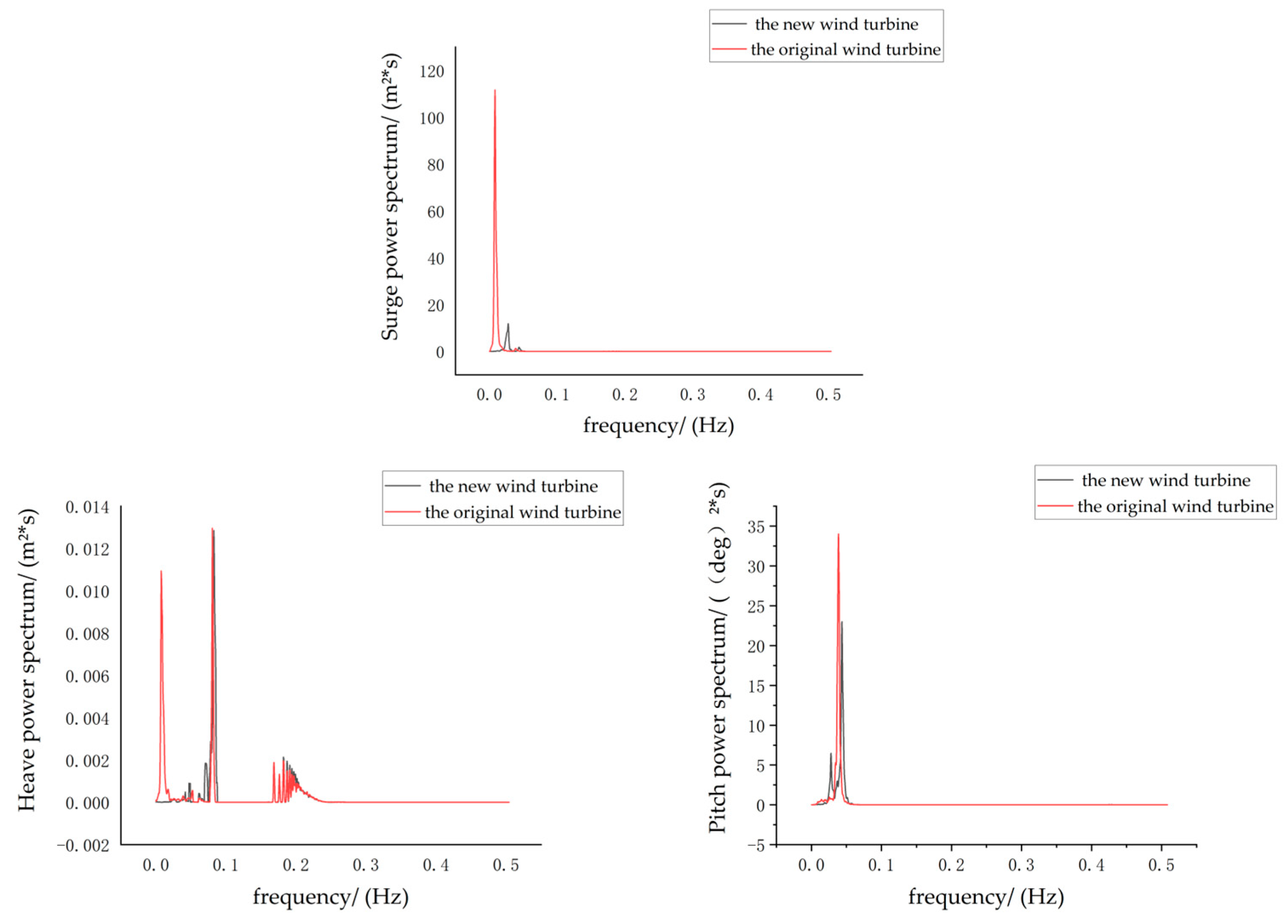
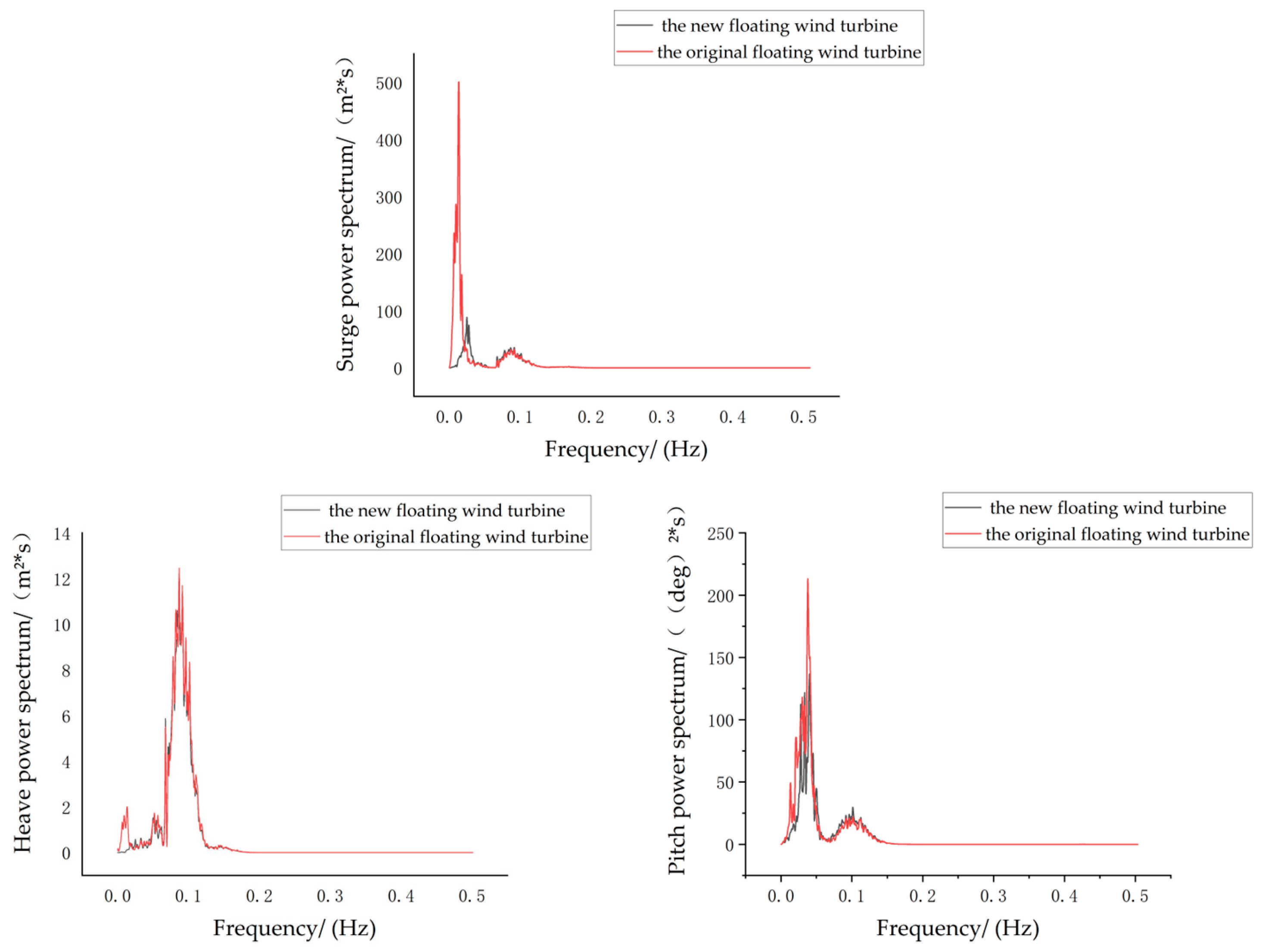
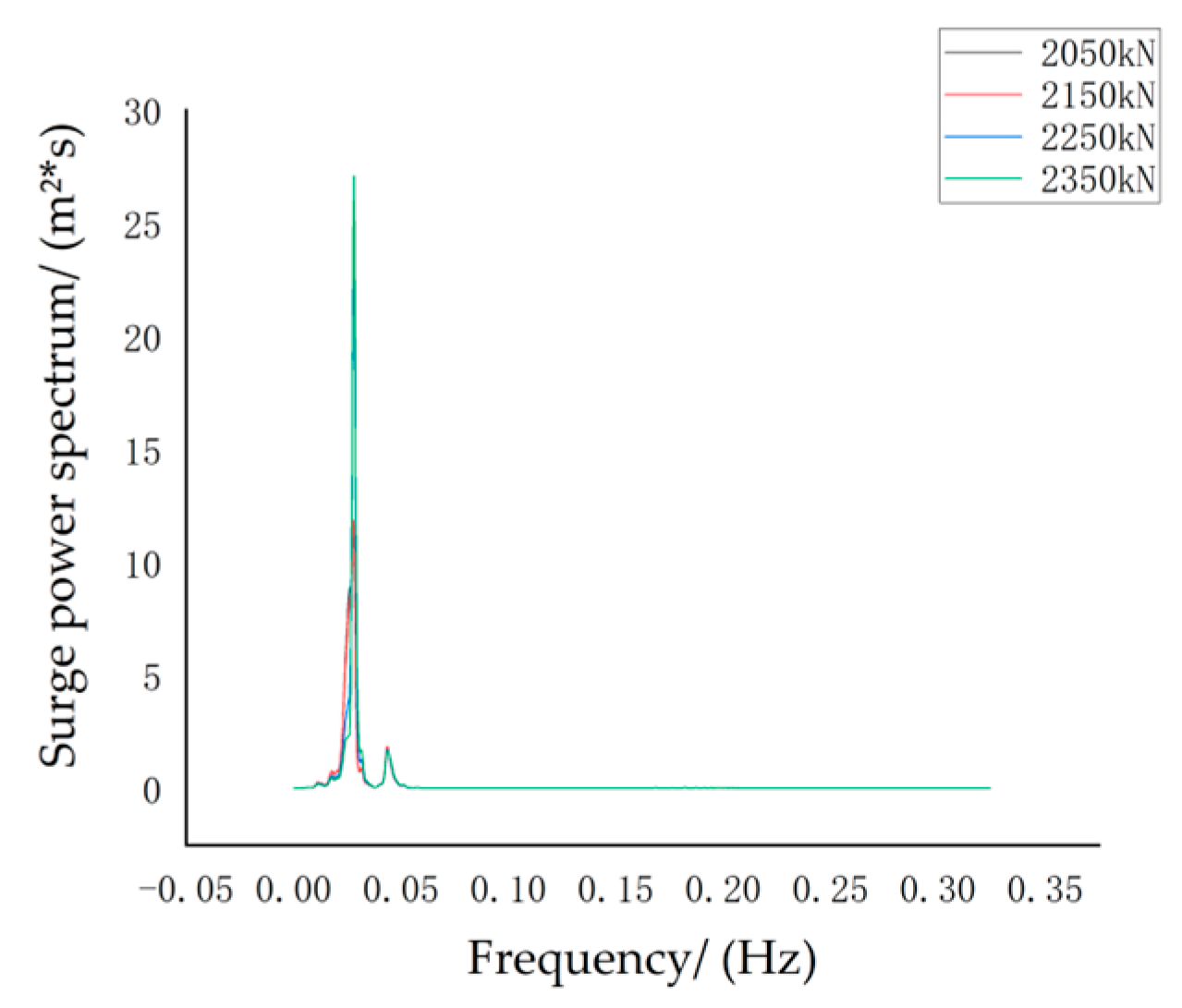
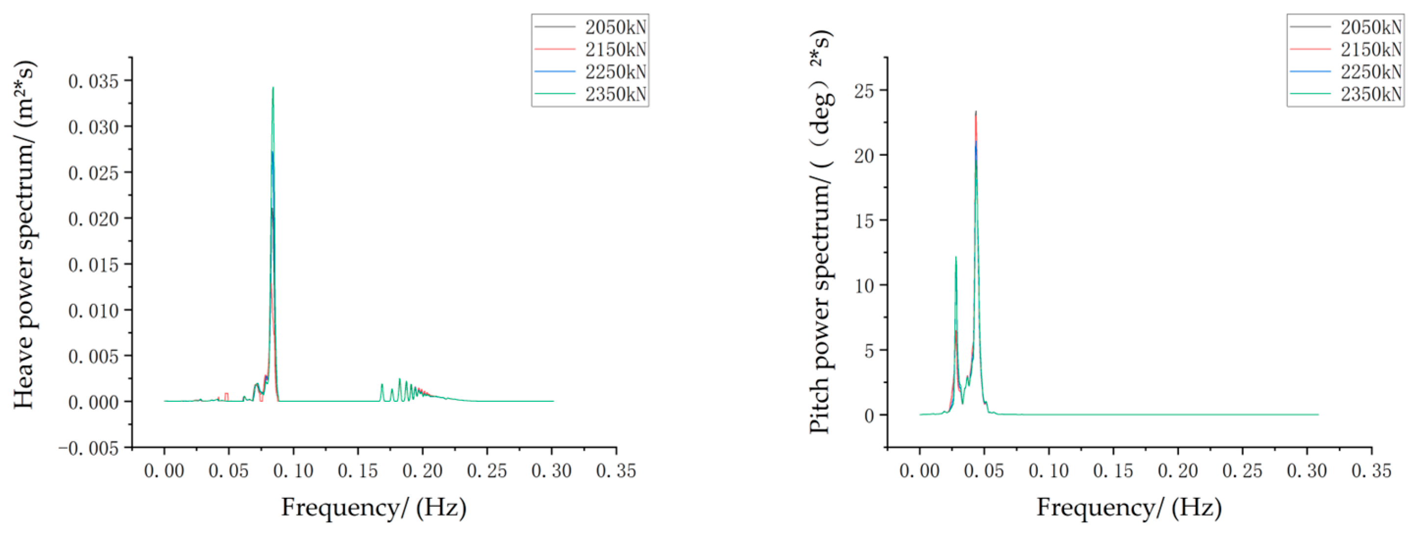
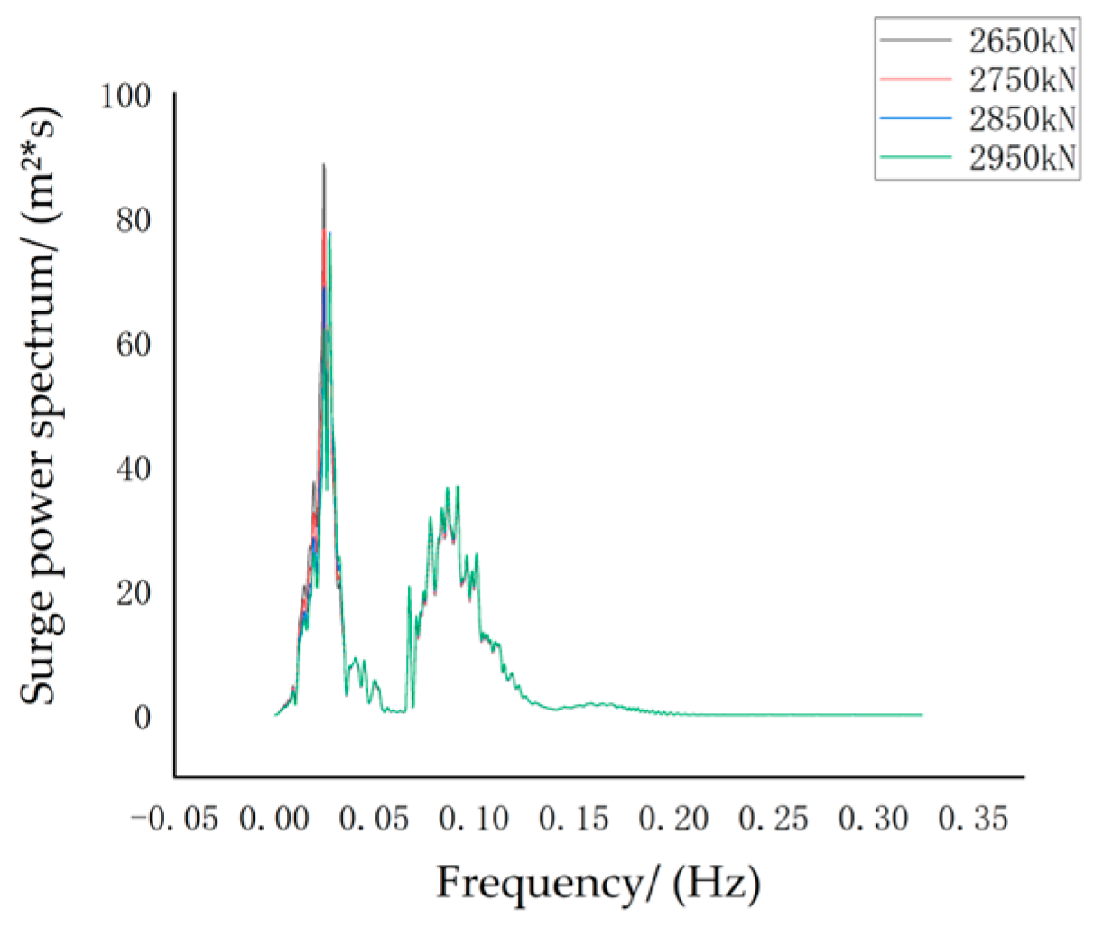
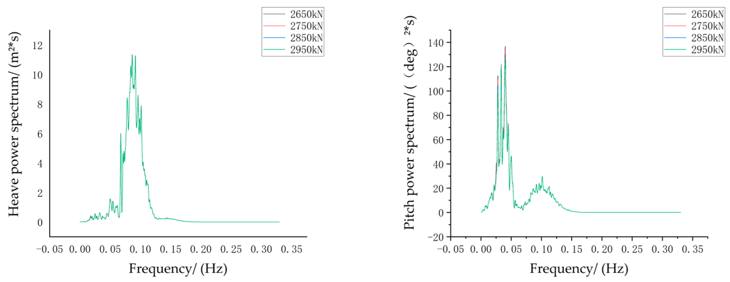
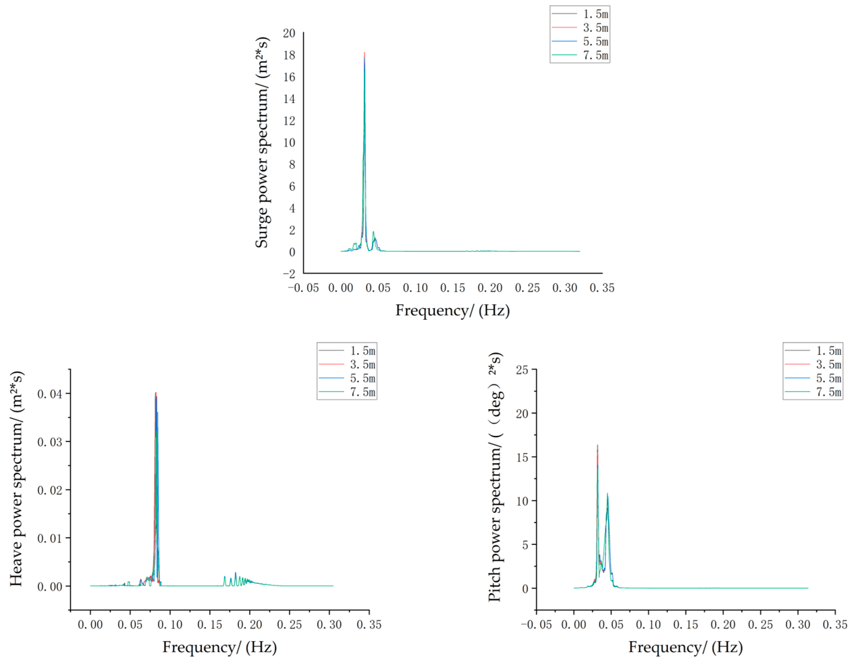
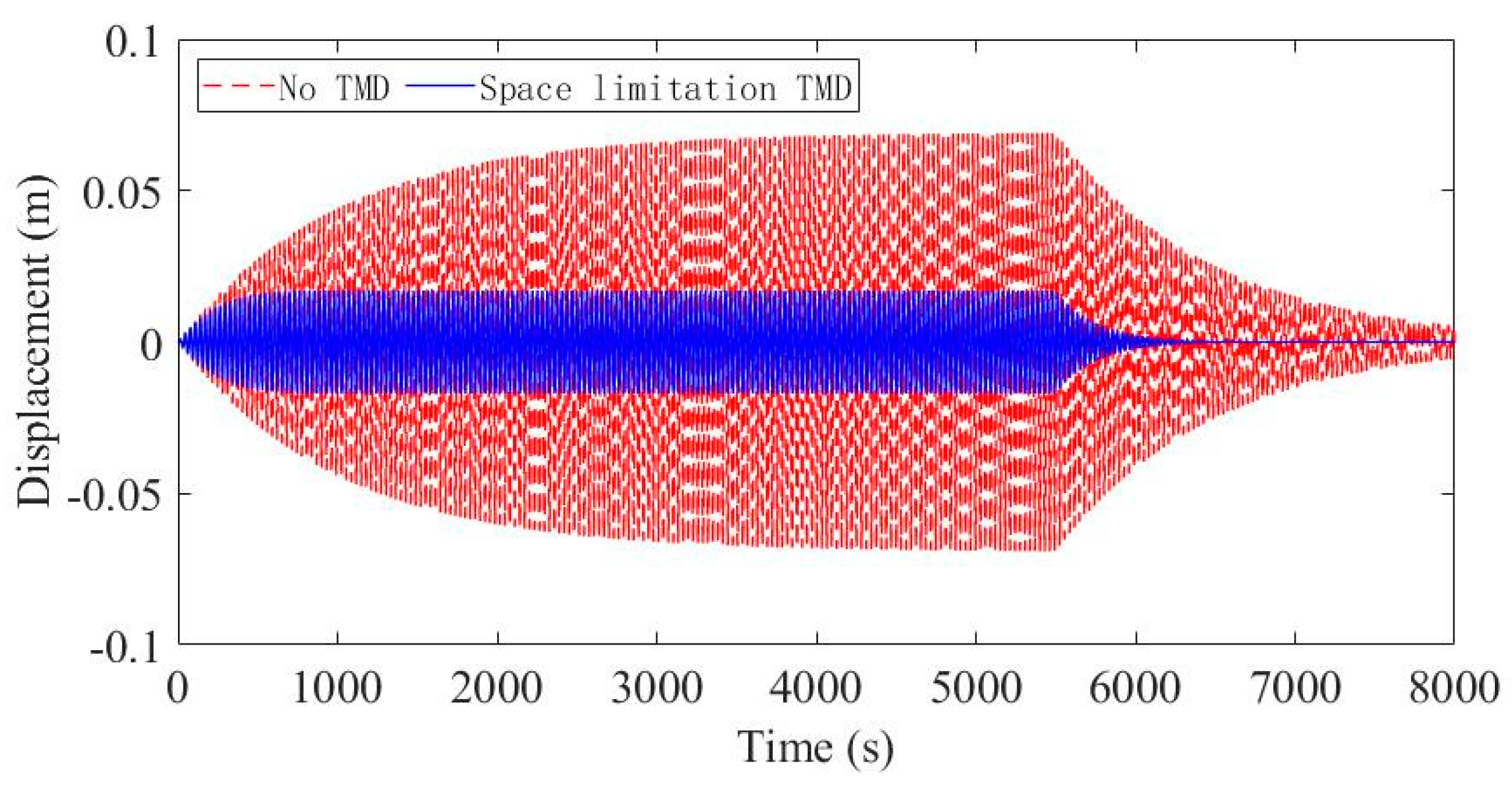
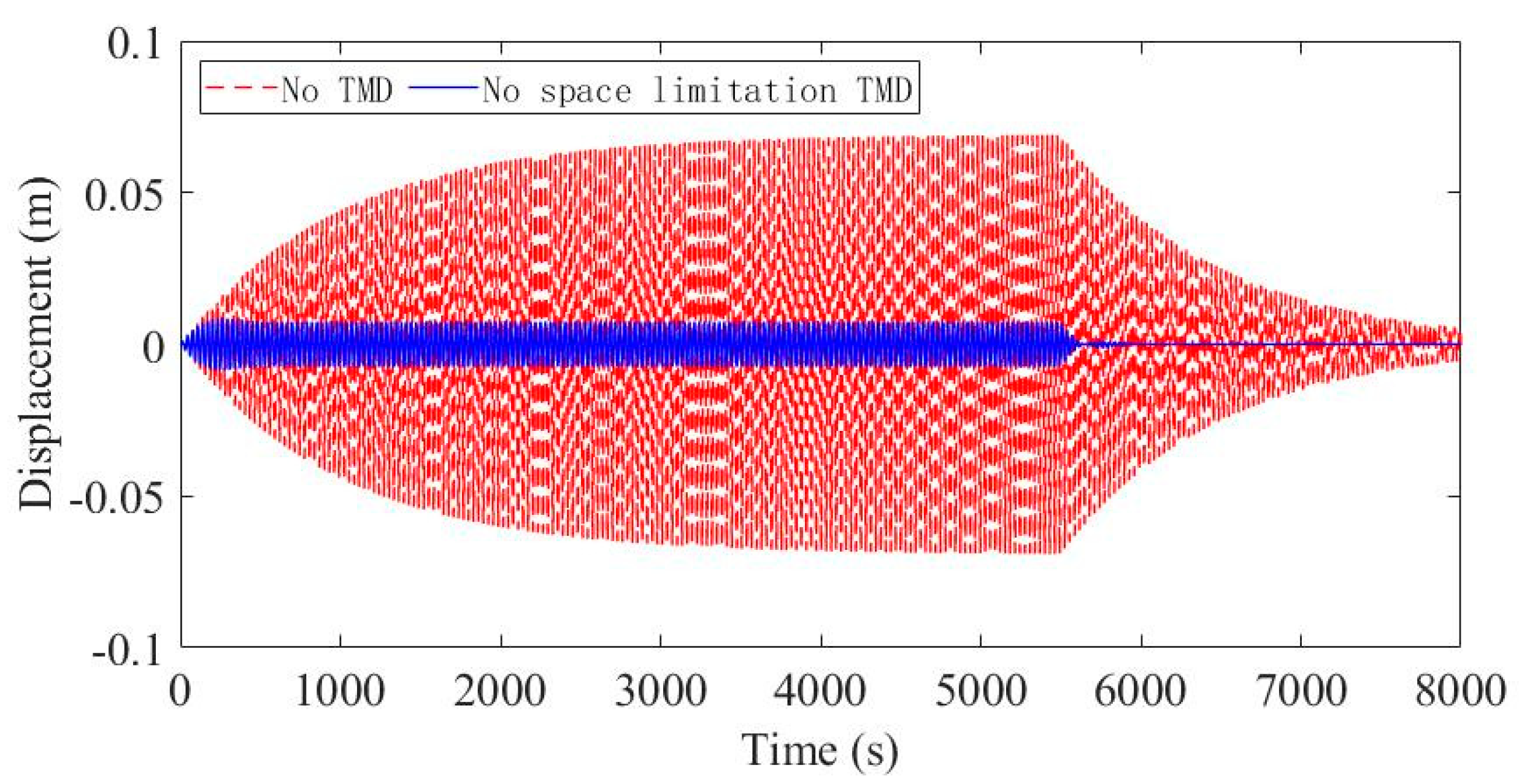
The newly proposed double-rope mooring system can overcome the shortcomings of the single-rope mooring system by considering both the vibration reduction performance and fatigue resistance performance. The new double-rope mooring system consists of the main rope, auxiliary rope, anchor device, and the links connecting the main rope and auxiliary rope. The novel double-rope mooring system was modeled in OrcaFlex, and the advantages of the double-rope mooring system compared with the original single-rope mooring system for the vibration control of the floating wind turbine platform were analyzed under normal operating conditions and storm self-existing conditions. The results show that, compared with the original single-rope mooring system, the vibration response of the floating wind turbine with a double-rope mooring system is significantly reduced. The influence of the variation in rope pretension and the position of the fairlead on the vibration response of the floating wind turbine is not obvious.
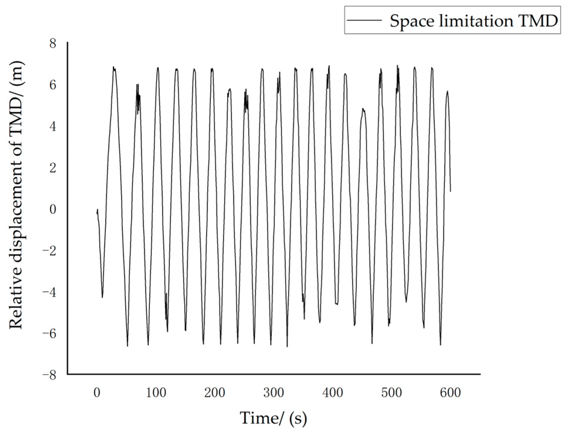
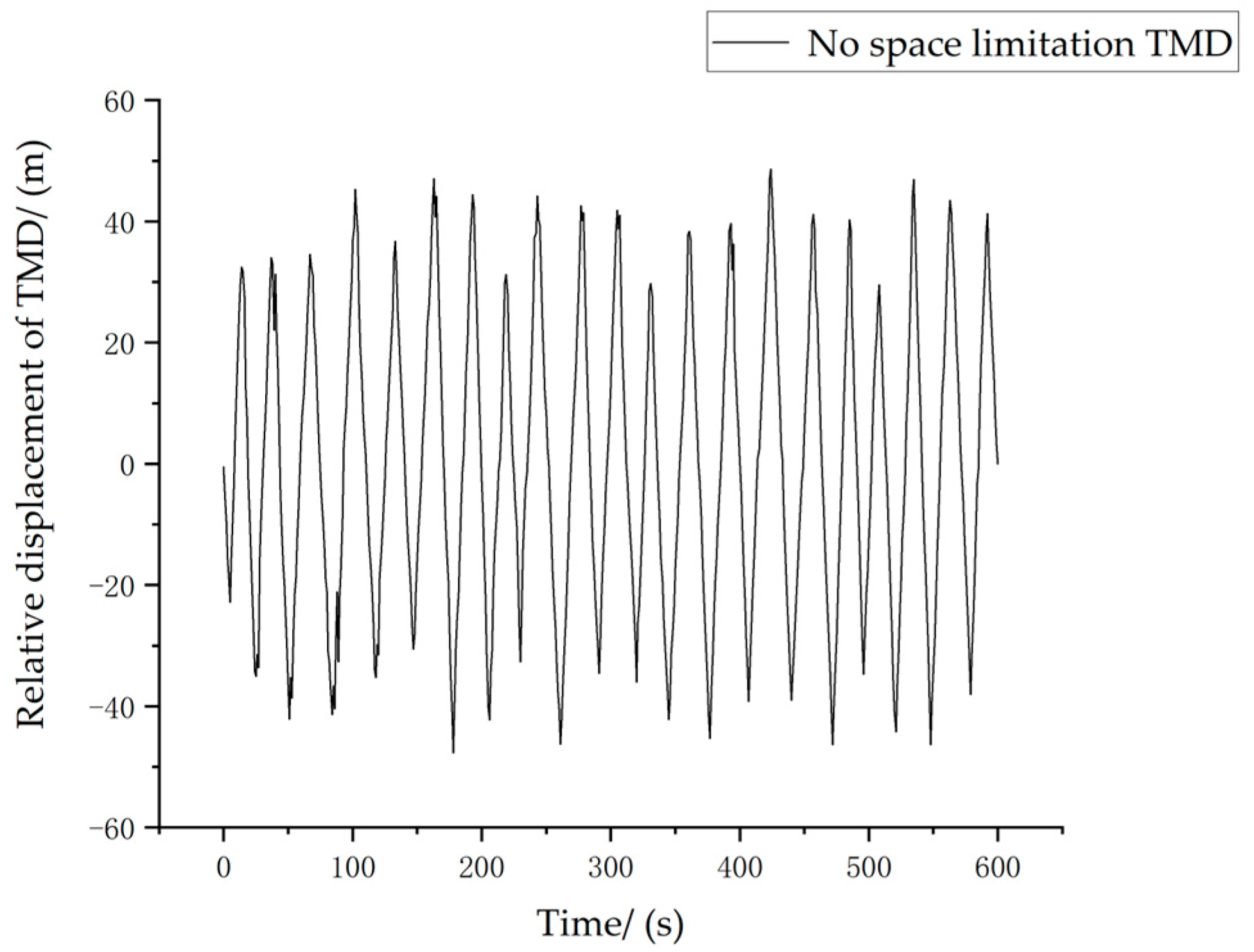
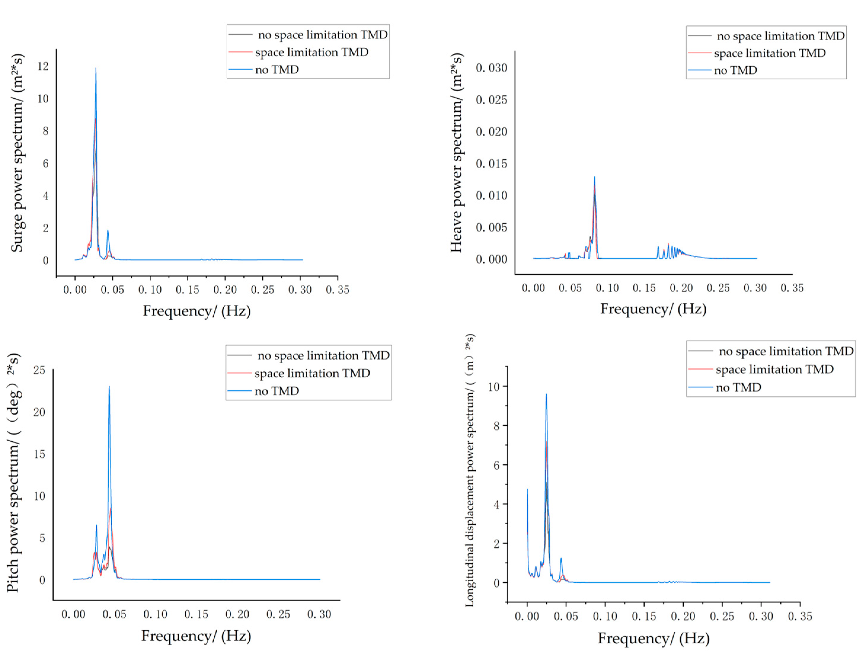
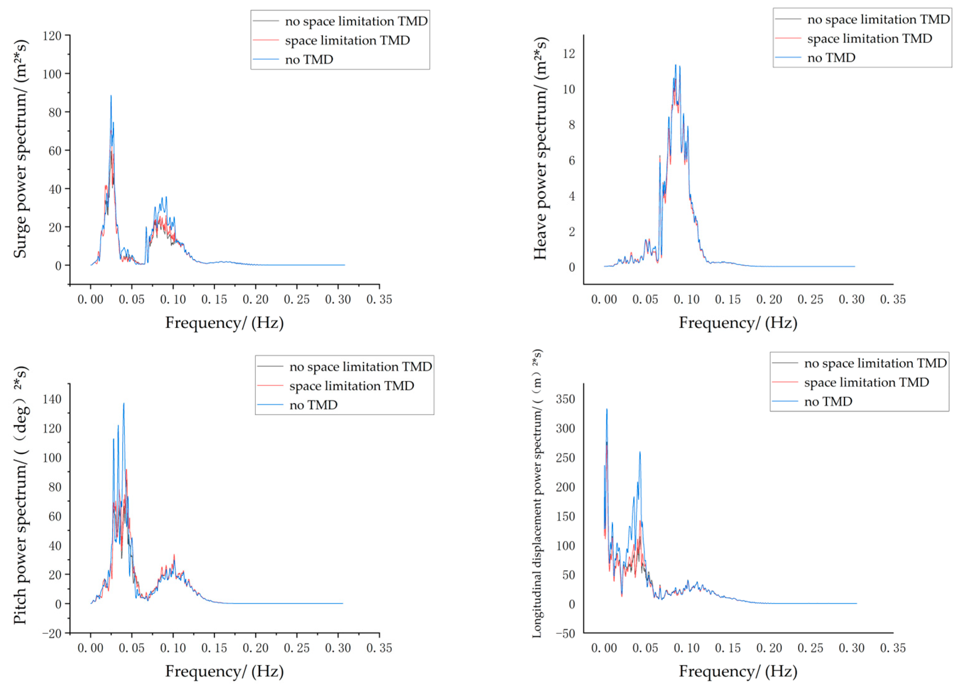
According to the SDOF-TMD optimization theory, related formulas of SDOF-TMD for vibration control were derived, and the TMD stiffness parameter and damping parameter were optimized. Considering the nacelle space constraint, TMD parameters need to be optimized under TMD stroke restrictions. The dynamic simulation analysis of the semi-submersible floating wind turbine with a double-rope mooring system under certain sea conditions was carried out, in which TMD with and without stroke limitation and without TMD was compared for their vibration reduction performance. The equivalent damping ratios of the floating wind turbine with stroke-limited TMD and stroke-unlimited TMD and without TMD were compared and analyzed. The results show that the installation of TMD has an obvious vibration-reduction effect on the floating wind turbine, and the vibration-reduction effect of TMD without stroke restrictions is more obvious than that of TMD with stroke limitations. However, considering the actual situation, it is necessary to impose stroke limitations on TMD.

Author Contributions

Conceptualization, Z.F. and X.H.; Methodology, Z.F.; Software, Y.H. and J.D.; Validation, Y.H. and J.D.; Formal analysis, Y.H. and Z.F.; Investigation, Y.H. and Z.F.; Resources, Z.F.; Data curation, Y.H. and Z.F.; Writing—original draft preparation, Y.H., Z.F., J.D. and H.J.; Writing—review and editing, Z.F. and H.J.; Visualization, Y.H.; Supervision, Z.F. and X.H.; Project administration, Z.F.; Funding acquisition, Z.F. All authors have read and agreed to the published version of the manuscript.

Funding

This research was funded by the Natural Science Foundation of Chongqing (grant No. 2022NSCQ-MSX5727) and the Natural Science Foundation of Hunan Province (grant No. 2021JJ30106).

Institutional Review Board Statement

Not applicable.

Informed Consent Statement

Not applicable.

Data Availability Statement

All data in this study have been included in the paper.

Acknowledgments

The authors would like to thank the reviewers for their time and effort in reviewing the manuscript, especially one of the anonymous reviewers who provided detailed and constructive suggestions after each round of revision. We sincerely appreciate all valuable comments and suggestions that help us improve the quality of our manuscript.

Conflicts of Interest

The authors declare no conflict of interest.

References

  1. Sahu, B.K. Wind Energy Developments and Policies in China: A Short Review. Renew. Sustain. Energy Rev. 2018, 81, 1393–1405. [Google Scholar] [CrossRef]
  2. Keivanpour, S.; Ramudhin, A.; Ait Kadi, D. The Sustainable Worldwide Offshore Wind Energy Potential: A Systematic Review. J. Renew. Sustain. Energy 2017, 9, 065902. [Google Scholar] [CrossRef]
  3. Patryniak, K.; Collu, M.; Coraddu, A. Multidisciplinary Design Analysis and Optimisation Frameworks for Floating Offshore Wind Turbines: State of the Art. Ocean Eng. 2022, 251, 111002. [Google Scholar] [CrossRef]
  4. Liu, S.; Yang, Y.; Wang, C.; Tu, Y.; Liu, Z. Proposal of a Novel Mooring System Using Three-Bifurcated Mooring Lines for Spar-Type Off-Shore Wind Turbines. Energies 2021, 14, 8303. [Google Scholar] [CrossRef]
  5. Liu, S.; Yang, Y.; Wang, C.; Tu, Y. Proposal and Performance Study of a Novel Mooring System with Six Mooring Lines for Spar-Type Offshore Wind Turbines. Appl. Sci. 2021, 11, 11665. [Google Scholar] [CrossRef]
  6. Park, G.; Oh, K.-Y.; Nam, W. Parent Nested Optimizing Structure for Vibration Reduction in Floating Wind Turbine Structures. JMSE 2020, 8, 876. [Google Scholar] [CrossRef]
  7. Jahangiri, V.; Sun, C. Three-Dimensional Vibration Control of Offshore Floating Wind Turbines Using Multiple Tuned Mass Dampers. Ocean Eng. 2020, 206, 107196. [Google Scholar] [CrossRef]
  8. Liu, Z.; Tu, Y.; Wang, W.; Qian, G. Numerical Analysis of a Catenary Mooring System Attached by Clump Masses for Improving the Wave-Resistance Ability of a Spar Buoy-Type Floating Offshore Wind Turbine. Appl. Sci. 2019, 9, 1075. [Google Scholar] [CrossRef] [Green Version]
  9. Ma, Y.; Chen, C.; Fan, T.; Lu, H. Research on the Dynamic Behaviors of a Spar Floating Offshore Wind Turbine With an Innovative Type of Mooring System. Front. Energy Res. 2022, 10, 853448. [Google Scholar] [CrossRef]
  10. Piscopo, V.; Scamardella, A.; Rossi, G.B.; Crenna, F.; Berardengo, M. Fatigue Assessment of Moorings for Floating Offshore Wind Turbines by Advanced Spectral Analysis Methods. J. Mar. Sci. Eng. 2022, 10, 37. [Google Scholar] [CrossRef]
  11. Dinh, V.-N.; Basu, B. Passive Control of Floating Offshore Wind Turbine Nacelle and Spar Vibrations by Multiple Tuned Mass Dampers. Struct. Control Health Monit. 2015, 22, 152–176. [Google Scholar] [CrossRef]
  12. Li, C.; Zhuang, T.; Zhou, S.; Xiao, Y.; Hu, G. Passive Vibration Control of a Semi-Submersible Floating Offshore Wind Turbine. Appl. Sci. 2017, 7, 509. [Google Scholar] [CrossRef] [Green Version]
  13. Han, D.; Wang, W.; Li, X.; Su, X. Optimization Design of Multiple Tuned Mass Dampers for Semi-Submersible Floating Wind Turbine. Ocean Eng. 2022, 264, 112536. [Google Scholar] [CrossRef]
  14. Jahangiri, V.; Sun, C. A Novel Three Dimensional Nonlinear Tuned Mass Damper and Its Application in Floating Offshore Wind Turbines. Ocean Eng. 2022, 250, 110703. [Google Scholar] [CrossRef]
  15. Zhang, Z. Vibration Suppression of Floating Offshore Wind Turbines Using Electromagnetic Shunt Tuned Mass Damper. Renew. Energy 2022, 198, 1279–1295. [Google Scholar] [CrossRef]
  16. Sarkar, S.; Fitzgerald, B. Fluid Inerter for Optimal Vibration Control of Floating Offshore Wind Turbine Towers. Eng. Struct. 2022, 266, 114558. [Google Scholar] [CrossRef]
  17. Sarkar, S.; Fitzgerald, B. Vibration Control of Spar-type Floating Offshore Wind Turbine Towers Using a Tuned Mass-damper-inerter. Struct. Control Health Monit. 2020, 27, e2471. [Google Scholar] [CrossRef]
  18. Zhang, Z.; Høeg, C. Dynamics and Control of Spar-Type Floating Offshore Wind Turbines with Tuned Liquid Column Dampers. Struct. Control Health Monit. 2020, 27, e2532. [Google Scholar] [CrossRef]
  19. Coulling, A.J.; Goupee, A.J.; Robertson, A.N.; Jonkman, J.M.; Dagher, H.J. Validation of a FAST Semi-Submersible Floating Wind Turbine Numerical Model with DeepCwind Test Data. J. Renew. Sustain. Energy 2013, 5, 023116. [Google Scholar] [CrossRef]
  20. Butterfield, S.; Musial, W.; Scott, G. Definition of a 5-MW Reference Wind Turbine for Offshore System Development; National Renewable Energy Laboratory: Golden, CO, USA, 2009. [Google Scholar]
  21. Robertson, A.; Jonkman, J.; Masciola, M.; Song, H.; Goupee, A.; Coulling, A.; Luan, C. Definition of the Semisubmersible Floating System for Phase II of OC4; National Renewable Energy Laboratory: Golden, CO, USA, 2014. [Google Scholar]
  22. Le, C.; Li, Y.; Ding, H.; Yang, J. Study on Motion Characteristics of A New Type Submerged Floating Wind Turbine Under Wave Load. Acta Energ. Sol. Sin. 2020, 41, 78–84. [Google Scholar]
  23. Feikema, G.J.; Wichers, J.E.W. The Effect of Wind Spectra on the Low-Frequency Motions of a Moored Tanker in Survival Condition. In Proceedings of the All Days, OTC, Houston, TX, USA, 6 May 1991; p. OTC-6605-MS. [Google Scholar]
  24. Hasselmann, K.; Barnett, T.P.; Bouws, E.; Carlson, H.; Cartwright, D.E.; Enke, K.; Ewing, J.A.; Gienapp, H.; Hasselmann, D.E.; Kruseman, P.; et al. Measurements of Wind-Wave Growth and Swell Decay during the Joint North Sea Wave Project (JONSWAP); Deutches Hydrographisches Institut: Hamburg, Germany, 1973; pp. 1–94. [Google Scholar]
  25. He, E.-M.; Hu, Y.-Q.; Zhang, Y. Optimization Design of Tuned Mass Damper for Vibration Suppression of a Barge-Type Offshore Floating Wind Turbine. Proc. Inst. Mech. Eng. Part M J. Eng. Marit. Environ. 2017, 231, 302–315. [Google Scholar] [CrossRef]
Figure 1. The original floating wind turbine.
Jmse 11 00058 g001
Figure 2. Schematic diagrams of three mooring systems: (a) Taut-moored system; (b) Catenary mooring system; (c) Double-rope mooring system.
Jmse 11 00058 g002
Figure 3. Model of floating wind turbine with double-rope mooring system.
Jmse 11 00058 g003
Figure 4. Schematic diagram of the floating wind turbine with TMD.
Jmse 11 00058 g004
Figure 5. Controlled model of the floating wind turbine with TMD.
Jmse 11 00058 g005
Figure 6. Comparison of platform movement in frequency domain under normal operating condition.
Jmse 11 00058 g006
Figure 7. Comparison of platform movement in frequency domain under storm self-survival condition.
Jmse 11 00058 g007
Figure 8. Frequency domain comparison under different rope pretension in normal operating conditions.
Jmse 11 00058 g008aJmse 11 00058 g008b
Figure 9. Frequency domain comparison under different rope pretensions in storm self-survival conditions.
Jmse 11 00058 g009aJmse 11 00058 g009b
Figure 10. Frequency domain comparison of different auxiliary rope fairlead positions under normal operating conditions.
Jmse 11 00058 g010
Figure 11. Frequency domain motion comparison with different auxiliary rope fairlead positions under storm self-survival conditions.
Jmse 11 00058 g011
Figure 12. Schematic diagram of TMD.
Jmse 11 00058 g012
Figure 13. Relative displacement of stroke-limited TMD.
Jmse 11 00058 g013
Figure 14. Relative displacement of TMD without stroke restriction.
Jmse 11 00058 g014
Figure 15. Comparison of FOWT responses in frequency domain under normal operating conditions.
Jmse 11 00058 g015
Figure 16. Comparison of floating wind turbine response in frequency domain under storm self-survival conditions.
Jmse 11 00058 g016
Figure 17. Comparison of free decay of floating wind turbine with stroke-limited TMD and without TMD.
Jmse 11 00058 g017
Figure 18. Comparison of free decay of floating wind turbine with stroke-unlimited TMD and without TMD.
Jmse 11 00058 g018
Table 1. Parameters of the NREL 5 MW baseline wind turbine.
ItemUnitValue
Rated powerMW5
Cut-in wind speedm/s3
Rated wind speedm/s11.4
Cut-out wind speedm/s25
Rotor diameterm126
Rated rotor speedr/min12.1
Hub diameterm3
Tower heightm77.6
Rotor masst110
Tower masst347.46
Nacelle masst240
Table 2. Parameters of OC4-DeepCwind semi-submersible platform.
ItemUnitValue
Draftm20
Buoy heightm26
Buoy diameterm12
Total masst13,473
Mass of the ballast watert3700
Center of mass below SWLm13.46
Roll moment of inertiakg∙m26.827 × 109
Pitch moment of inertiakg∙m26.827 × 109
Yaw moment of inertiakg∙m21.226 × 1010
Table 3. Parameters of mooring system.
ItemUnitValue
Number of mooring lines/3
Angle between adjacent lines°120
Depth to fairleads below SWLm14
Depth to anchors below SWLm199.825
Initial length of mooring linem835.5
Mooring line extensional stiffnessN7.5 × 108
Table 4. Parameters of NPD spectrum in normal operating condition.
ItemUnitValue
Wind speedm/s13.2
Directiondeg180
Frequency (min)Hz0.00167
Frequency (max)Hz0.43
Table 5. Parameters of Jonswap spectrum in normal operating condition.
ItemUnitValue
WaveHsm3.1
WaveTss2.77
Directiondeg180
Relative Frequency rangeHz0.5~10
Table 6. Parameters of NPD spectrum in storm self-survival condition.
ItemUnitValue
Wind speedm/s36.4
Directiondeg180
Frequency (min)Hz0.00378
Frequency (max)Hz0.56
Table 7. Parameters of Jonswap spectrum in storm self-survival condition.
ItemUnitValue
WaveHsm11.1
WaveTss7.11
Directiondeg180
Relative frequency rangeHz0.5~10
Table 8. The first 20 modes of the original wind turbine.
Period (s)Frequency (Hz)Modal Characteristic
Mode 193.45930.0107Surge
Mode 289.94250.0111
Mode 387.14900.0115
Mode 485.35110.0117Sway
Mode 564.03480.0156
Mode 663.77380.0157Yaw
Mode 720.62050.0485Pitch
Mode 820.54830.0487Roll
Mode 920.34860.0491
Mode 1020.33050.0492
Mode 1113.07030.0765
Mode 1212.99950.0769
Mode 1312.97630.0771
Mode 1412.91520.0774
Mode 1512.89500.0776
Mode 1612.87020.0777
Mode 1712.41390.0806Heave
Mode 1812.41330.0806
Mode 196.77540.1476
Mode 206.68830.1495
Table 9. The first 20 modes of the new wind turbine.
Period (s)Frequency (Hz)Modal Characteristic
Mode 132.53730.03073Yaw
Mode 231.03780.03222Surge
Mode 329.87960.03347Sway
Mode 418.71410.05344Pitch
Mode 518.5740.05384Roll
Mode 613.12370.0762
Mode 713.10320.07632
Mode 813.07750.07647
Mode 912.43250.08043Heave
Mode 109.045320.11055
Mode 118.696510.11499
Mode 128.682410.11518
Mode 136.679390.14971
Mode 146.664290.15005
Mode 156.662290.1501
Mode 166.584120.15188
Mode 176.571820.15216
Mode 186.569110.15223
Mode 195.498630.18186
Mode 205.459350.18317
Table 10. RMS of responses to two types of wind turbine under normal operating condition.
The Original Floating Wind TurbineThe New Floating Wind Turbine
Surge (m)0.63040.2502
Heave (m)0.01150.0109
Pitch (deg)0.40930.3565
Table 11. RMS of responses to two types of wind turbine under storm self-survival condition.
The Original Floating Wind TurbineThe New Floating Wind Turbine
Surge (m)2.20071.4208
Heave (m)0.59230.5706
Pitch (deg)2.03001.7449
Table 12. Response RMS of different rope pretensions under normal operating conditions.
Surge (m)Heave (m)Pitch (deg)
2050 kN0.25180.01110.3574
2150 kN0.25020.01090.3565
2250 kN0.26780.01210.3593
2350 kN0.27010.01280.3576
Table 13. Response RMS of different rope pretensions under storm self-survival conditions.
Surge (m)Heave (m)Pitch (deg)
2050 kN1.42080.57061.7449
2150 kN1.40530.57011.7346
2250 kN1.39280.56961.7246
2350 kN1.38480.56911.7174
Table 14. Motion RMS with different auxiliary rope fairlead positions under normal operating conditions.
Surge (m)Heave (m)Pitch (deg)
−1.5 m0.25390.01260.3522
−3.5 m0.25650.01270.3554
−5.5 m0.25420.01260.3564
−7.5 m0.25180.01110.3574
Table 15. Motion RMS with different auxiliary rope fairlead positions under storm self-survival conditions.
Surge (m)Heave (m)Pitch (deg)
−1.5 m1.42310.56471.7325
−3.5 m1.42490.56491.7407
−5.5 m1.42240.56551.7438
−7.5 m1.42080.57061.7449
Table 16. Optimization results of TMD parameters.
No Stroke RestrictionStroke Restriction
Frequency ratio0.990141.03252
Damping ratio0.059490.16764
Stiffness coefficient ( N · m 1 )15,795.717,176.8
Damping coefficient ( Ns · m 1 )17,739.152,127.6
Table 17. Motion RMS with or without TMD stroke limitation under normal operating conditions.
Stroke-Limited TMDStroke-Unlimited TMDNo TMD
Surge (m)0.19870.17430.2502
Heave (m)0.01050.01040.0109
Pitch (deg)0.24450.19820.3565
The longitudinal displacement response of the tower (m)0.17260.14870.2376
Table 18. Motion RMS with or without TMD stroke limitation under storm self-survival conditions.
Stroke-Limited TMDStroke-Unlimited TMDNo TMD
Surge (m)1.21191.09971.4208
Heave (m)0.56890.56730.5706
Pitch (deg)1.38551.21791.7449
The longitudinal displacement response of the tower (m)2.38472.10672.8662
Disclaimer/Publisher’s Note: The statements, opinions and data contained in all publications are solely those of the individual author(s) and contributor(s) and not of MDPI and/or the editor(s). MDPI and/or the editor(s) disclaim responsibility for any injury to people or property resulting from any ideas, methods, instructions or products referred to in the content.

