
Marine Internet of Things Platforms for Interoperability of Marine Robotic Agents: An Overview of Concepts and Architectures

Abstract
:1. Introduction
- Ocean sounding and monitoring—a general system for monitoring the marine environment, formerly a long-established system using oceanographic and hydrographic research vessels;
- Water quality monitoring—generally for tracking water conditions and quality, including water temperature, pH, turbidity, conductivity, and dissolved oxygen content in ocean bays, lakes, rivers, and other bodies of water;
- Coral reef monitoring—tracks coral reef habitat and the environment;
- Monitoring deep-sea fish farms—tracks water state and quality, including temperature and pH, measures fecal waste and uneaten food, as well as fish condition, including number of dead species;
- Wave and current monitoring—measures waves and currents for safe and reliable navigation;
- Ocean pollution monitoring—includes chemical and biological analysis of ocean pollution and temperature analysis;
- Analysis of pressure and temperature changes for given areas;
- Monitoring oil and gas field areas and pipelines.
2. Features and Differences of MIoT from IoT
- The heterogeneity and versatility of the system elements determine that the system must provide intermediary communication, providing interaction between underwater, surface, air and ground elements (underwater robots, surface ships, buoy systems and underwater stations, UAVs, coastal operator stations);
- Various possibilities of communication channels (especially bandwidth) require the development of a special model for the information interaction of system elements;
- Computational limitations for data processing operations by on-board computers;
- Low power consumption and the ability to generate and store energy leads to the need to apply energy conservation, generation and storage measures in the system elements;
- High equipment reliability imposes higher demands on equipment reliability due to aggressive marine environment. Sensors, actuators and other assemblies are required to have a very high level of watertightness. There is a need for auxiliary devices, such as buoys and mooring devices, etc.
2.1. Hydroacoustic Communication Means
- (1).
- Hydroacoustic micromodem “uWave”. The device allows you to provide hydro-acoustic digital communication between 20 callers within a radius of up to 1000 m with a transmission speed of 70 bps, using the code mode and transparent channel mode. The extremely small size of 41 × 45 mm, low power consumption, and ease of use make “uWAVE” the ideal solution for AUV control, as well as data transmission.
- (2).
- Hydroacoustic modem “uWAVE Max”. The device is designed to transmit data over a hydroacoustic channel at a distance of 3 km, even in complex hydrological conditions and in shallow water at a speed of 80 bps. The small size of 64 × 62 mm, low power consumption, and ease of use make uWAVE Max the ideal solution for both small ROVs/UUVs and larger devices.
- (1).
- “S2C M 30/60” underwater acoustic modems. The “S2C M 30/60” modems and USBL transceivers with near hemispherical transducer diagrams are high-speed devices for efficient transmission in reverberant waters, providing data rates of up to 31.2 kbps in the 1000 m range.
- (2).
- “18/34H” underwater acoustic modems. These are devices for communication in reverberant shallow waters, providing data rates up to 13.9 kbps in the 3500 m range. The wide-angle beam pattern is optimal for vertical, oblique and horizontal transmissions. The high operating frequency ensures high performance even in noisy environments.
- (3).
- “15/27” underwater acoustic modems. “15/27” modems are deep-lying devices for long-range transmissions, providing data rates up to 9.2 kbps in the 6000 m range. The beam pattern with wide coverage is optimal for vertical and oblique transmissions to/from stationary systems. Nominal depth and operating frequency provide high performance for long-range transmissions between the seafloor and the surface.
2.2. Optical Communications Means
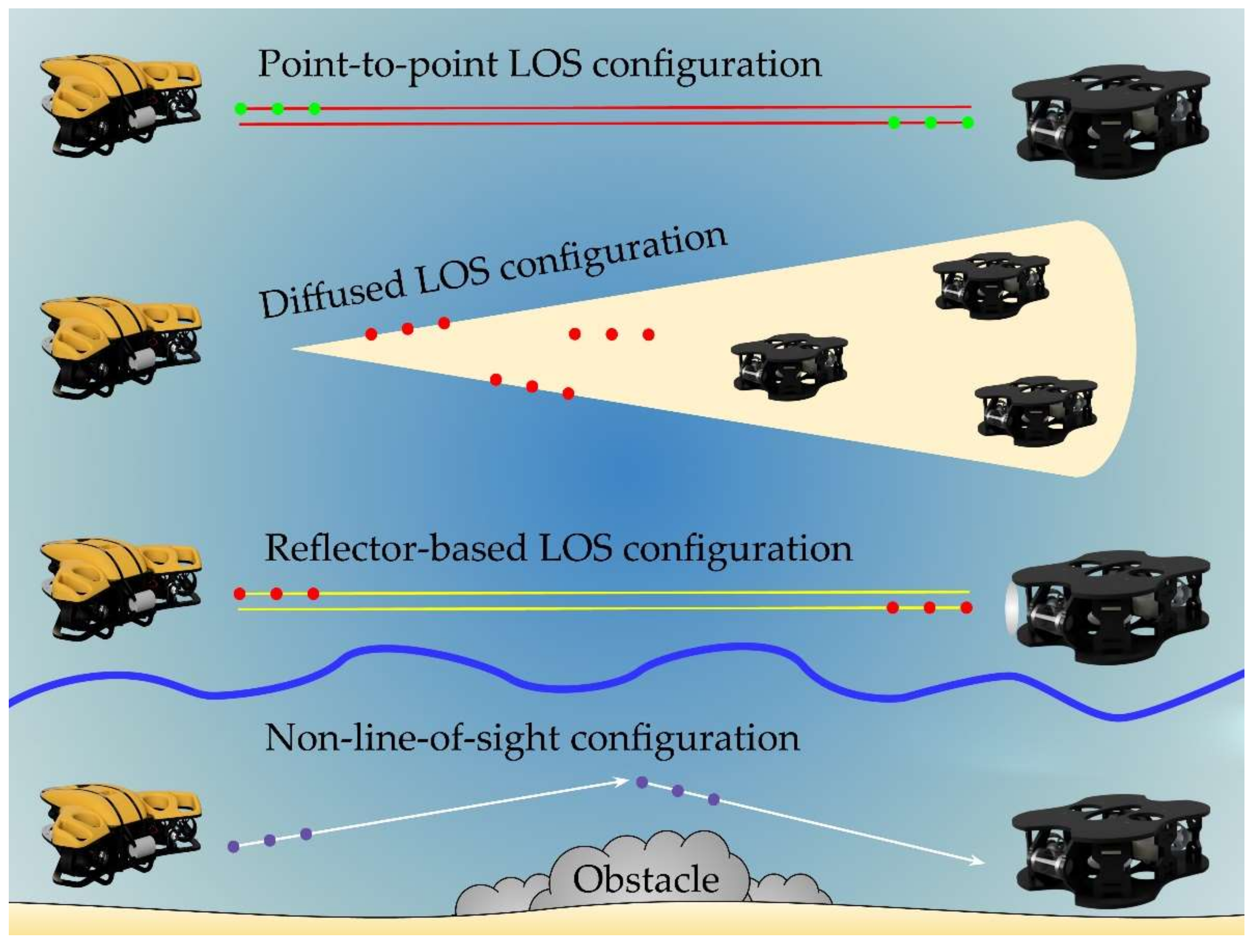
- Point-to-point line-of-sight configuration;
- Diffused line-of-sight configuration;
- Direct visibility configuration based on a reflector;
- Non-line-of-sight configuration.
- The optical signal is strongly attenuated and diffused;
- Underwater optical channels can be temporarily interrupted due to optical transceiver mismatch and obstacles.
2.3. Radiofrequency Communication Means
- Allowing electromagnetic signals to cross the water-to-air boundary and provide long-range horizontal communications using the air path, followed by air-to-water signal transmission if necessary;
- Studying the phenomenon of guided waves on the water side of the water–air interface.
2.4. Combined Use of Different Communication Means
3. Analysis of Approaches to the Formation of the Architecture of MIoT Systems
3.1. MIoT Network Architecture
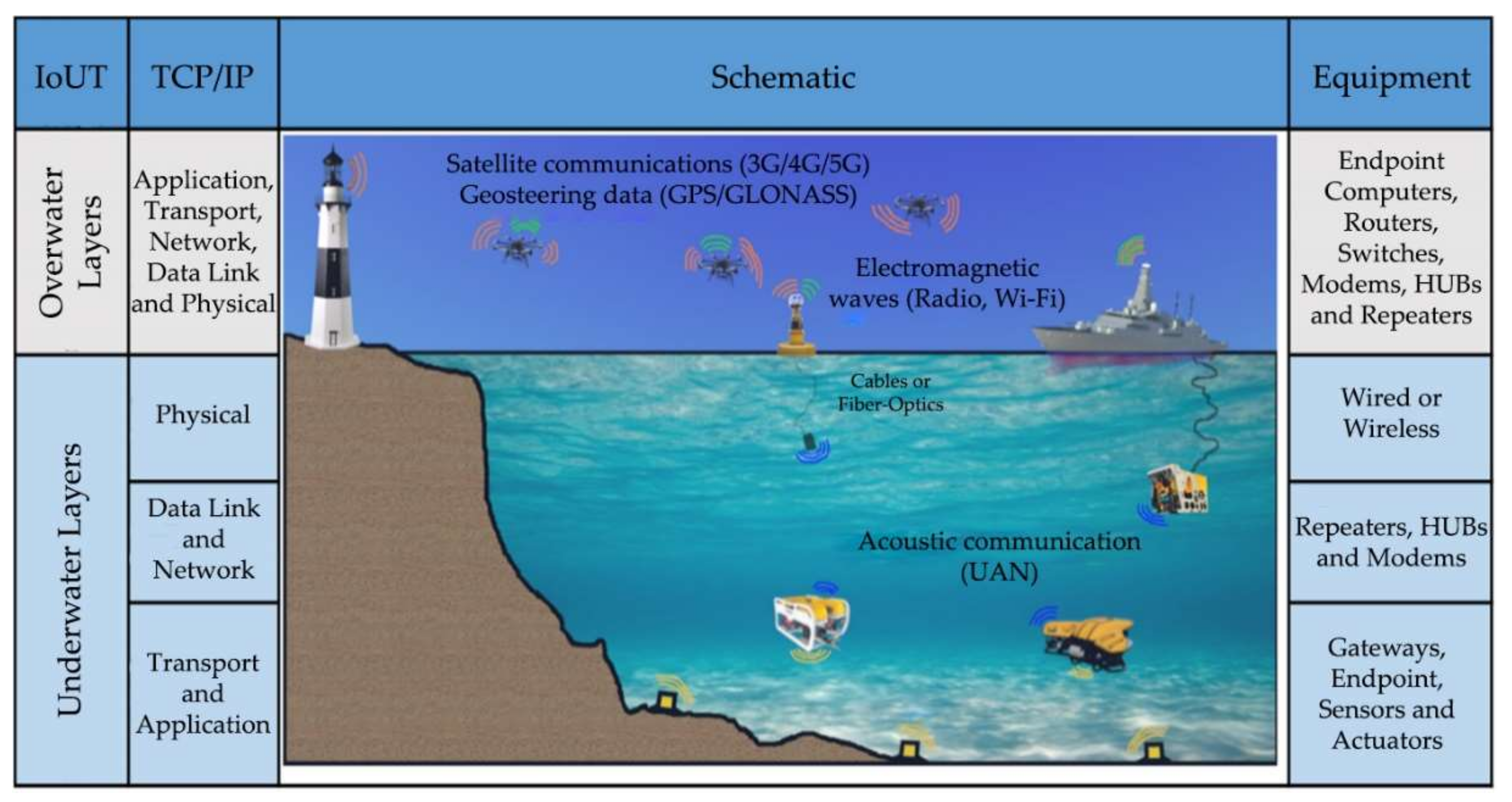
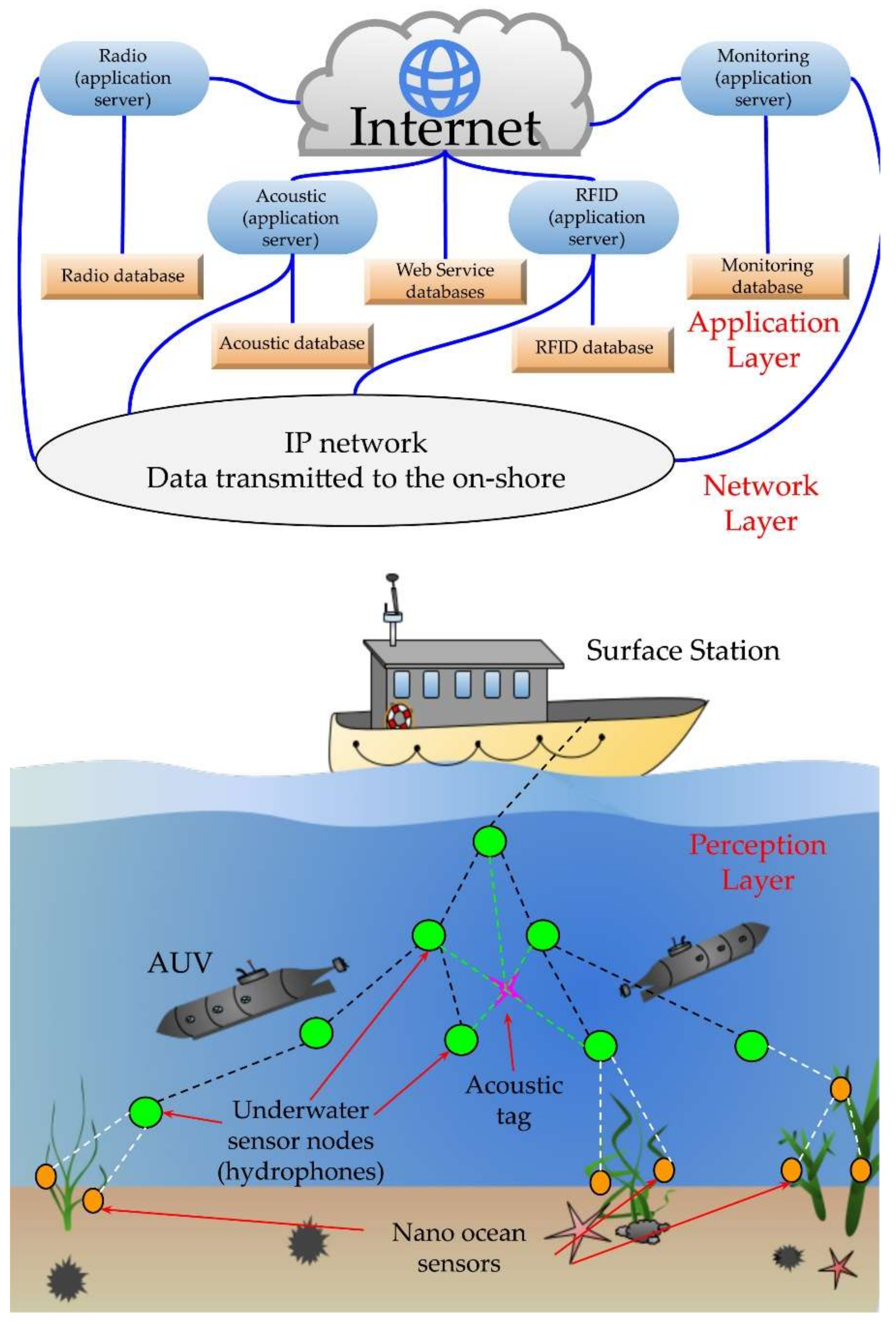
- The application layer in MIoT is responsible for identifying each individual object (e.g., sensor ID, sensor type, sensor location, etc.) and then collecting data, processing information, and delivering commands. Data collection at the application level includes data detection, recording, and streaming. Some actuators may also belong to this layer to respond to the environment according to given instructions, or based on a machine learning model. These actuators can be recorded and monitored through the MIoT platform. Existing IoT systems have a sufficient number of application layer protocols to meet all technological requirements in various IoT applications. However, not all of these protocols are suitable for MIoT (IoUT) applications. Some of the application-layer protocols rely on broadband operation, while others have protocol headers that are redundant for underwater communication, without any significant impact on communication reliability.
- Transport Layer: Given the nature of the data created by a particular service, the transport layer is responsible for separating the data into packets before passing it through the network gateway. This layer also takes into account the order of the data and its potential loss.
- Network Layer: The main tasks of the network layer include the bi-directional sending of data packets between individual endpoints as well as protocol translation between neighboring layers. These tasks are performed at the network layer by implementing both Internet protocol (IP) and data routing. Along with Internet protocols, there are network layer routing protocols that determine how routers communicate with each other. An efficient data routing scheme is an integral part of any UWC system.
- The channel layer supports underwater sensor access to the surface stations by appropriately sending/receiving data from the physical layer, as well as coordinating the sending of data. This data exchange with the physical environment requires a conversion between data frames depending on the underlying communication technology (acoustic, electromagnetic, and optical).
- 5.
- The physical layer demonstrates different behavior in response to various propagation modes and different types of channels. Signal attenuation is calculated differently for electromagnetic, acoustic and optical media. Regardless of the types of propagation technologies, an appropriate channel model is needed. This model can be used to predict communication system performance, design optimal node locations, and reduce overall system power consumption prior to actual deployment.
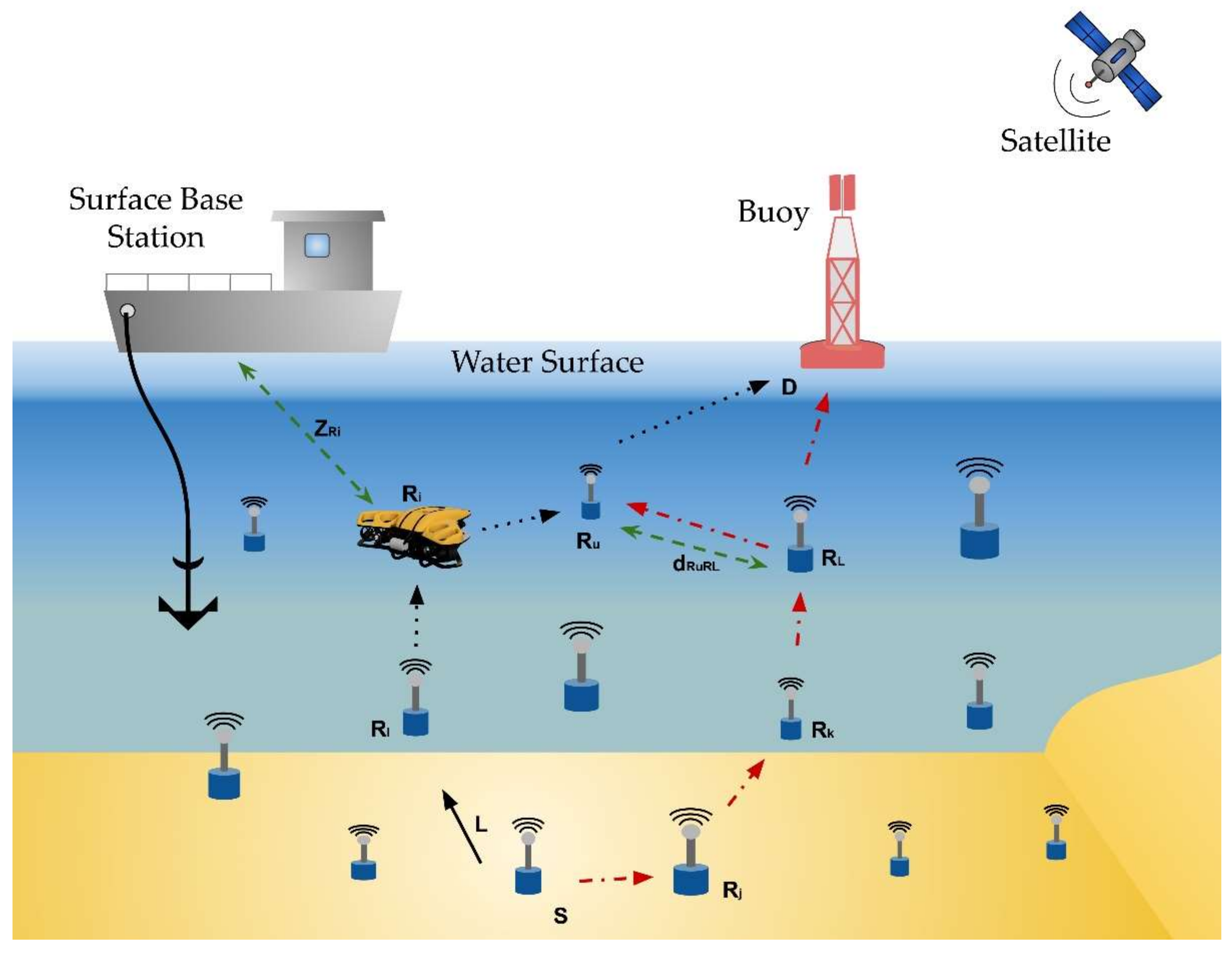
3.2. MIoT Architecture Based on a Data Transfer Scenario
3.3. Functionality-Based MIoT Architecture
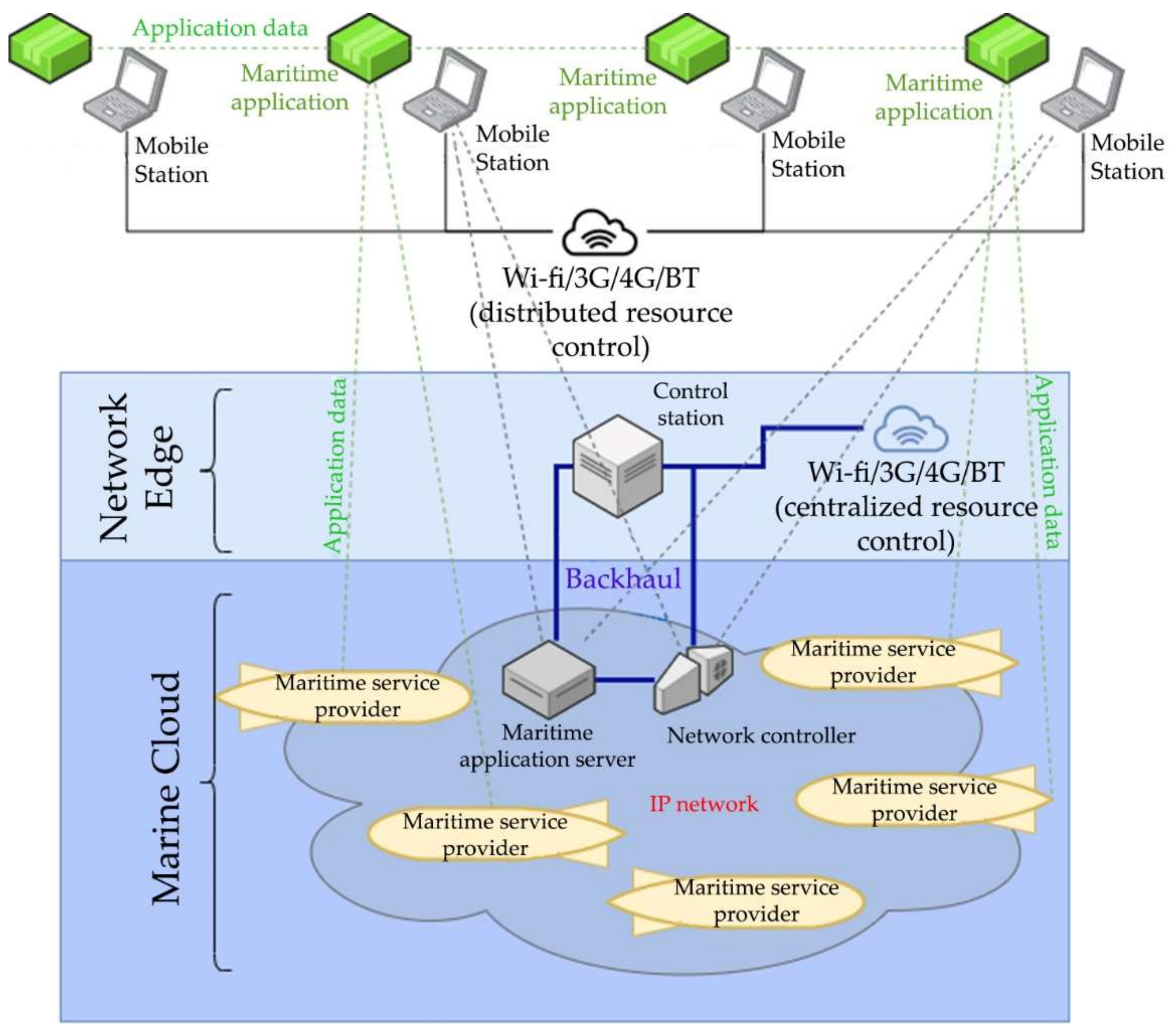
3.4. Common MIoT-Based System Architectures
4. Discussion
- The standardization of MIoT devices specifically designed to monitor and protect the marine environment, including sensors and actuators, routers, and gateways;
- The standardization of MIoT platforms and system technologies for monitoring and protecting the marine environment, including communication network structures, protocols, and algorithms;
- The standardization of computing and data storage technologies for monitoring and protecting the marine environment, including cloud, fog and edge computing mechanisms, data archiving, and storing methods;
- The standardization of data analysis results and reporting formats for sharing between different organizations and governments.
5. Conclusions
Author Contributions
Funding
Institutional Review Board Statement
Informed Consent Statement
Data Availability Statement
Conflicts of Interest
References
- Salhaoui, M.; Molina-Molina, J.C.; Guerrero-González, A.; Arioua, M.; Ortiz, F.J. Autonomous Underwater Monitoring System for Detecting Life on the Seabed by Means of Computer Vision Cloud Services. Remote Sens. 2020, 12, 1981. [Google Scholar] [CrossRef]
- Jahanbakht, M.; Xiang, W.; Hanzo, L.; Rahimi Azghadi, M. Internet of Underwater Things and Big Marine Data Analytics—A Comprehensive Survey. IEEE Commun. Surv. Tutor. 2021, 23, 904–956. [Google Scholar] [CrossRef]
- Kong, M.; Guo, Y.; Sait, M.; Alkhazragi, O.; Kang, C.H.; Ng, T.K.; Ooi, B.S. Underwater Optical Wireless Sensor Network for Real-Time Underwater Environmental Monitoring. In Next-Generation Optical Communication: Components, Sub-Systems, and Systems XI; Li, G., Nakajima, K., Eds.; SPIE: San Francisco, CA, USA, 2022; p. 22. [Google Scholar] [CrossRef]
- Domingo, M.C. An overview of the internet of underwater things. J. Netw. Comput. Appl. 2012, 35, 1879–1890. [Google Scholar] [CrossRef]
- Xu, G.; Shi, Y.; Sun, X.; Shen, W. Internet of Things in Marine Environment Monitoring: A Review. Sensors 2019, 19, 1711. [Google Scholar] [CrossRef] [PubMed]
- Kao, C.-C.; Lin, Y.-S.; Wu, G.-D.; Huang, C.-J. A Comprehensive Study on the Internet of Underwater Things: Applications, Challenges, and Channel Models. Sensors 2017, 17, 1477. [Google Scholar] [CrossRef]
- Khan, A.; Jenkins, L. Undersea wireless sensor network for ocean pollution prevention. In Proceedings of the 2008 3rd International Conference on Communication Systems Software and Middleware and Workshops (COMSWARE ’08), Bangalore, India, 6–10 January 2008; pp. 2–8. [Google Scholar] [CrossRef]
- Alippi, C.; Camplani, R.; Galperti, C.; Roveri, M. A Robust, Adaptive, Solar-Powered WSN Framework for Aquatic Environmental Monitoring. IEEE Sens. J. 2011, 11, 45–55. [Google Scholar] [CrossRef]
- Manjula, R.B.; Manvi, S.S. Coverage optimization based sensor deployment by using PSO for anti-submarine detection in UWASNs. In Proceedings of the 2013 Ocean Electronics (SYMPOL), Kochi, India, 23–25 October 2013; pp. 15–22. [Google Scholar] [CrossRef]
- Khaledi, S.; Mann, H.; Perkovich, J.; Zayed, S. Design of an underwater mine detection system. In Proceedings of the 2014 Systems and Information Engineering Design Symposium (SIEDS), Charlottesville, VA, USA, 25 April 2014; pp. 78–83. [Google Scholar] [CrossRef]
- Cayirci, E.; Tezcan, H.; Dogan, Y.; Coskun, V. Wireless sensor networks for underwater survelliance systems. Ad Hoc Netw. 2006, 4, 431–446. [Google Scholar] [CrossRef]
- Yushi, L.; Fei, J.; Hui, Y. Study on application modes of military Internet of Things (MIOT). In Proceedings of the 2012 IEEE International Conference on Computer Science and Automation Engineering (CSAE), Zhangjiajie, China, 25–27 May 2012; pp. 630–634. [Google Scholar] [CrossRef]
- Cardia, C.; Gjanci, P.; Petrioli, C.; Saturni, G.; Spaccini, D.; Tomaselli, D. The Internet of Underwater Things: From Nemo to Underwater Whatsapp. In Proceedings of the Twentieth ACM International Symposium on Mobile Ad Hoc Networking and Computing; ACM: Catania, Italy, 2019; pp. 409–410. [Google Scholar] [CrossRef]
- Coutinho, R.W.L.; Boukerche, A. Topology Control for Internet of Underwater Things. In Proceedings of the 15th ACM International Symposium on QoS and Security for Wireless and Mobile Networks—Q2SWinet’19; ACM Press: Miami Beach, FL, USA, 2019; pp. 79–83. [Google Scholar] [CrossRef]
- Kong, M.; Guo, Y.; Alkhazragi, O.; Sait, M.; Kang, C.H.; Ng, T.K.; Ooi, B.S. Real-Time Optical-Wireless Video Surveillance System for High Visual-Fidelity Underwater Monitoring. IEEE Photonics J. 2022, 14, 1–9. [Google Scholar] [CrossRef]
- Kong, M.; Guo, Y.; Sait, M.; Alkhazragi, O.; Kang, C.H.; Ng, T.K.; Ooi, B.S. Toward Automatic Subsea Operations Using Real-Time Underwater Optical Wireless Sensor Networks. IEEE Photonics J. 2022, 14, 1–8. [Google Scholar] [CrossRef]
- Marini, S.; Gjeci, N.; Govindaraj, S.; But, A.; Sportich, B.; Ottaviani, E.; Márquez, F.P.G.; Bernalte Sanchez, P.J.; Pedersen, J.; Clausen, C.V.; et al. ENDURUNS: An Integrated and Flexible Approach for Seabed Survey Through Autonomous Mobile Vehicles. JMSE 2020, 8, 633. [Google Scholar] [CrossRef]
- Qin, C.; Du, J.; Wang, J.; Ren, Y. A Hierarchical Information Acquisition System for AUV Assisted Internet of Underwater Things. IEEE Access 2020, 8, 176089–176100. [Google Scholar] [CrossRef]
- Lin, M.; Yang, C. Ocean Observation Technologies: A Review. Chin. J. Mech. Eng. 2020, 33, 32. [Google Scholar] [CrossRef]
- Binnerts, B.; Mulders, I.; Blom, K.; Colin, M.; Dol, H. Development and Demonstration of a Live Data Streaming Capability Using an Underwater Acoustic Communication Link. In Proceedings of the 2018 OCEANS—MTS/IEEE Kobe Techno-Oceans (OTO), Kobe, Japan, 28–31 May 2018; pp. 1–7. [Google Scholar] [CrossRef]
- Lu, H.; Wang, D.; Li, Y.; Li, J.; Li, X.; Kim, H.; Serikawa, S.; Humar, I. CONet: A Cognitive Ocean Network. IEEE Wirel. Commun. 2019, 26, 90–96. [Google Scholar] [CrossRef]
- Saha, S.; Hasan Rajib, R.; Kabir, S. IoT Based Automated Fish Farm Aquaculture Monitoring System. In Proceedings of the 2018 International Conference on Innovations in Science, Engineering and Technology (ICISET), Chittagong, Bangladesh, 27–28 October 2018; IEEE: Chittagong, Bangladesh, 2018; pp. 201–206. [Google Scholar] [CrossRef]
- Li, D.; Miao, Z.; Peng, F.; Wang, L.; Hao, Y.; Wang, Z.; Chen, T.; Li, H.; Zheng, Y. Automatic counting methods in aquaculture: A review. J. World Aquac. Soc. 2021, 52, 269–283. [Google Scholar] [CrossRef]
- Fu, B.; Xiao, Y.; Deng, H.; Zeng, H. A Survey of Cross-Layer Designs in Wireless Networks. IEEE Commun. Surv. Tutor. 2014, 16, 110–126. [Google Scholar] [CrossRef]
- Available online: https://www.astrocast.com/ (accessed on 10 August 2022).
- Available online: https://www.singtel.com/business/products-services/satellite/maritime-satellite-services/maritime-iot (accessed on 10 August 2022).
- Wang, M.M.; Zhang, J. Machine-Type Communication for Maritime Internet-of-Things: From Concept to Practice; Springer: Cham, Switzerland, 2021. [Google Scholar] [CrossRef]
- Xia, T.; Wang, M.M.; Zhang, J.; Wang, L. Maritime Internet of Things: Challenges and Solutions. IEEE Wirel. Commun. 2020, 27, 188–196. [Google Scholar] [CrossRef]
- Yang, T.; Chen, J.; Zhang, N. AI-Empowered Maritime Internet of Things: A Parallel-Network-Driven Approach. IEEE Netw. 2020, 34, 54–59. [Google Scholar] [CrossRef]
- Hagen, J.E. Implementing E-Navigation; Artech House: Boston, MA, USA, 2017. [Google Scholar]
- Dol, H.S.; Casari, P.; van der Zwan, T.; Otnes, R. Software-Defined Underwater Acoustic Modems: Historical Review and the NILUS Approach. IEEE J. Ocean. Eng. 2017, 42, 722–737. [Google Scholar] [CrossRef]
- Luo, H.; Wu, K.; Ruby, R.; Liang, Y.; Guo, Z.; Ni, L.M. Software-Defined Architectures and Technologies for Underwater Wireless Sensor Networks: A Survey. IEEE Commun. Surv. Tutor. 2018, 20, 2855–2888. [Google Scholar] [CrossRef]
- Water Linked Modem M64. Available online: https://waterlinked.com/product/modem-m64/ (accessed on 21 September 2020).
- Campagnaro, F.; Signori, A.; Zorzi, M. Wireless Remote Control for Underwater Vehicles. JMSE 2020, 8, 736. [Google Scholar] [CrossRef]
- Popoto Modem. Available online: http://popotomodem.com/ (accessed on 10 August 2022).
- Available online: https://www.unavlab.com/produktsiya/peredacha-dannyh-pod-vodoj/ (accessed on 10 August 2022).
- Kebkal, K.; Kebkal, O.; Glushko, E.; Kebkal, V.; Sebastiao, L.; Pascoal, A.; Gomes, J.; Ribeiro, J.; Silva, H.; Ribeiro, M.; et al. Underwater Acoustic Modems with Integrated Atomic Clocks for One-Way Travel-Time Underwater Vehicle Positioning. In Proceedings of the UACE 2017—4th Underwater Acoustics Conference and Exhibition, Skiathos, Greece, 3–8 September 2017; Available online: http://www.uaconferences.org/docs/UACE2017_Papers/315_UACE2017.pdf (accessed on 10 August 2022).
- Kebkal, K.; Kebkal, O.; Kebkal, V.; Sebastião, L.; Pascoal, A.; Ribeiro, J.; Indivery, G.; Kelholt, E.; Jesus, S.; Mantouka, A. Performance Assessment of Underwater Acoustic Modems Operating Simultaneously at Different Frequencies in the Presence of Background Impulsive Noise Emitted by a Sparker. In Proceedings of the UACE2017—4th Underwater Acoustics Conference and Exhibition, Skiathos, Greece, 3–8 September 2017; Available online: http://www.uaconferences.org/docs/UACE2017_Papers/325_UACE2017.pdf (accessed on 10 August 2022).
- Available online: http://www.develogic.de/products/underwater-communication-systems/ham-base/ (accessed on 10 August 2022).
- Kaushal, H.; Kaddoum, G. Underwater Optical Wireless Communication. IEEE Access 2016, 4, 1518–1547. [Google Scholar] [CrossRef]
- Kakati, A.; Sharma, D.; Aggarwal, N.N. A Brief Survey On Underwater Wireless Optical Communication System. Int. J. Res. GRANTHAALAYAH 2018, 6, 238–245. [Google Scholar] [CrossRef]
- Zeng, Z.; Fu, S.; Zhang, H.; Dong, Y.; Cheng, J. A Survey of Underwater Optical Wireless Communications. IEEE Commun. Surv. Tutor. 2017, 19, 204–238. [Google Scholar] [CrossRef]
- Murgod, T.R.; Sundaram, S.M. Survey on underwater optical wireless communication: Perspectives and challenges. IJEECS 2019, 13, 138. [Google Scholar] [CrossRef]
- Saeed, N.; Celik, A.; Al-Naffouri, T.Y.; Alouini, M.-S. Underwater optical wireless communications, networking, and localization: A survey. Ad Hoc Netw. 2019, 94, 101935. [Google Scholar] [CrossRef]
- Shihada, B.; Amin, O.; Bainbridge, C.; Jardak, S.; Alkhazragi, O.; Ng, T.K.; Ooi, B.; Berumen, M.; Alouini, M.S. Aqua-Fi: Delivering Internet Underwater Using Wireless Optical Networks. IEEE Commun. Mag. 2020, 58, 84–89. [Google Scholar] [CrossRef]
- Spagnolo, G.S.; Cozzella, L.; Leccese, F. Underwater Optical Wireless Communications: Overview. Sensors 2020, 20, 2261. [Google Scholar] [CrossRef]
- Gkoura, L.K.; Roumelas, G.D.; Nistazakis, H.E.; Sandalidis, H.G.; Vavoulas, A.; Tsigopoulos, A.D.; Tombras, G.S. Underwater Optical Wireless Communication Systems: A Concise Review. In Turbulence Modelling Approaches—Current State, Development Prospects, Applications; Volkov, K., Ed.; InTech: Houston, TX, USA, 2017. [Google Scholar] [CrossRef]
- Popoola, W.O.; Geldard, C.; Guler, E.; Hamilton, A. Underwater optical wireless communication with subcarrier intensity modulation: An experimental demonstration. Proc. Meet. Acoust. 2021, 44, 032001. [Google Scholar] [CrossRef]
- Mohsan, S.A.H.; Hasan, M.M.; Mazinani, A.; Sadiq, M.A.; Akhtar, M.H.; Islam, A.; Rokia, L.S. A Systematic Review on Practical Considerations, Recent Advances and Research Challenges in Underwater Optical Wireless Communication. IJACSA 2020, 11, 162–172. [Google Scholar] [CrossRef]
- Johnson, L.J.; Jasman, F.; Green, R.J.; Leeson, M.S. Recent advances in underwater optical wireless communications. Underw. Technol. 2014, 32, 167–175. [Google Scholar] [CrossRef]
- Rich, C.; Longcore, T. (Eds.) Ecological Consequences of Artificial Night Lighting; Island Press: Washington, DC, USA, 2006. [Google Scholar]
- Tang, S.; Dong, Y.; Zhang, X. On path loss of NLOS underwater wireless optical communication links. In Proceedings of the 2013 MTS/IEEE OCEANS—Bergen, Bergen, Norway, 10–13 June 2013; pp. 1–3. [Google Scholar] [CrossRef]
- Centelles, D.; Soriano, A.; Marin, R.; Sanz, P.J. Wireless HROV Control with Compressed Visual Feedback Using Acoustic and RF Links. J. Intell. Robot. Syst. 2020, 99, 713–728. [Google Scholar] [CrossRef]
- Lloret, J.; Sendra, S.; Ardid, M.; Rodrigues, J.J.P.C. Underwater Wireless Sensor Communications in the 2.4 GHz ISM Frequency Band. Sensors 2012, 12, 4237–4264. [Google Scholar] [CrossRef] [PubMed]
- Shaw, A.; Al-Shamma’a, A.I.; Wylie, S.R.; Toal, D. Experimental Investigations of Electromagnetic Wave Propagation in Seawater. In Proceedings of the 2006 European Microwave Conference, Manchester, UK, 10–15 September 2006; pp. 572–575. [Google Scholar] [CrossRef]
- Zoksimovski, A.; Sexton, D.; Stojanovic, M.; Rappaport, C. Underwater electromagnetic communications using conduction—Channel characterization. Ad Hoc Netw. 2015, 34, 42–51. [Google Scholar] [CrossRef]
- Dautta, M.; Hasan, M.I. Underwater vehicle communication using electromagnetic fields in shallow seas. In Proceedings of the 2017 International Conference on Electrical, Computer and Communication Engineering (ECCE), Cox’s Bazar, Bangladesh, 16–18 February 2017; pp. 38–43. [Google Scholar] [CrossRef]
- Ali, M.F.; Jayakody, D.N.K.; Chursin, Y.A.; Affes, S.; Dmitry, S. Recent Advances and Future Directions on Underwater Wireless Communications. Arch. Comput. Methods Eng. 2020, 27, 1379–1412. [Google Scholar] [CrossRef]
- Wu, X.; Xue, W.; Shu, X. Design and implementation of underwater wireless electromagnetic communication system. In Proceedings of the AIP Conference Proceedings, Chongqing, China, 27–28 May 2017; p. 020022. [Google Scholar] [CrossRef]
- Tahir, M.; Ali, I.; Yan, P.; Jafri, M.R.; Zexin, J.; Xiaoqiang, D.; Exploiting, W. Ellison model for seawater communication at gigahertz frequencies based on world ocean atlas data. ETRI J. 2020, 42, 575–584. [Google Scholar] [CrossRef] [Green Version]
- Quintana-Díaz, G.; Mena-Rodríguez, P.; Pérez-Álvarez, I.; Jiménez, E.; Dorta-Naranjo, B.P.; Zazo, S.; Pérez, M.; Quevedo, E.; Cardona, L.; Hernández, J.J. Underwater Electromagnetic Sensor Networks—Part I: Link Characterization. Sensors 2017, 17, 189. [Google Scholar] [CrossRef]
- Zazo, J.; Valcarcel Macua, S.; Zazo, S.; Pérez, M.; Pérez-Álvarez, I.; Jiménez, E.; Cardona, L.; Brito, J.H.; Quevedo, E. Underwater Electromagnetic Sensor Networks, Part II: Localization and Network Simulations. Sensors 2016, 16, 2176. [Google Scholar] [CrossRef]
- Che, X.; Wells, I.; Dickers, G.; Kear, P.; Gong, X. Re-evaluation of RF electromagnetic communication in underwater sensor networks. IEEE Commun. Mag. 2010, 48, 143–151. [Google Scholar] [CrossRef]
- Pirinen, P. A Brief Overview of 5G Research Activities. In Proceedings of the 1st International Conference on 5G for Ubiquitous Connectivity, Akaslompolo, Finland, 26–28 November 2014 . [Google Scholar] [CrossRef]
- Wu, J.; Ma, X.; Qi, X.; Babar, Z.; Zheng, W. Influence of Pulse Shaping Filters on PAPR Performance of Underwater 5G Communication System Technique: GFDM. Wirel. Commun. Mob. Comput. 2017, 2017, 1–7. [Google Scholar] [CrossRef]
- Khalighi, M.A.; Uysal, M. Survey on Free Space Optical Communication: A Communication Theory Perspective. IEEE Commun. Surv. Tutor. 2014, 16, 2231–2258. [Google Scholar] [CrossRef]
- Vasilescu, I.; Detweiler, C.; Rus, D. AquaNodes: An underwater sensor network. In Proceedings of the Annual International Conference on Mobile Computing and Networking MOBICOM, Montreal, QC, Canada, 9–14 September 2017; pp. 85–88. [Google Scholar] [CrossRef]
- Wang, J.; Shen, J.; Shi, W.; Qiao, G.; Wu, S.; Wang, X. A Novel Energy-Efficient Contention-Based MAC Protocol Used for OA-UWSN. Sensors 2019, 19, 183. [Google Scholar] [CrossRef] [PubMed]
- Anees, S.; Baruah, S.R.; Sarma, P. Hybrid RF-FSO System Cascaded with UWOC Link. Int. J. Innov. Technol. Explor. Eng. 2019, 8, 2065–2069. [Google Scholar] [CrossRef]
- Kataria, A.; Ghosh, S.; Karar, V.; Gupta, T.; Srinivasan, K.; Hu, Y.-C. Improved Diver Communication System by Combining Optical and Electromagnetic Trackers. Sensors 2020, 20, 5084. [Google Scholar] [CrossRef]
- Lim, Y.; Park, J. Efficient Data Forwarding for Machine Type Communications in Internet of Things Networks. Wirel. Commun. Mob. Comput. 2017, 2017, 1–7. [Google Scholar] [CrossRef]
- Kuai, M.; Haque, T.; Hong, X.; Yu, Q. A Named-Data Networking Approach to Underwater Monitoring Systems. In Proceedings of the 10th International Conference on Underwater Networks & Systems—WUWNET ’15, Arlington, VA, USA, 22–24 October 2015; pp. 1–2. [Google Scholar] [CrossRef]
- Jacobson, V.; Smetters, D.K.; Thornton, J.D.; Plass, M.F.; Briggs, N.H.; Braynard, R.L. Networking named content. In Proceedings of the 5th international conference on Emerging networking experiments and technologies—CoNEXT ’09, Rome, Italy, 1–4 December 2009; p. 1. [Google Scholar] [CrossRef]
- Fall, K.; Farrell, S. DTN: An architectural retrospective. IEEE J. Sel. Areas Commun. 2008, 26, 828–836. [Google Scholar] [CrossRef]
- Rahman, R.H.; Frater, M.R. Delay-Tolerant Networks (DTNs) for Underwater Communications. In Advances in Delay-Tolerant Networks (DTNs); Elsevier: Amsterdam, The Netherlands, 2021; pp. 79–101. ISBN 978-0-08-102793-6. [Google Scholar]
- Rahman, R.H.; Frater, M.R. Delay-Tolerant Networks (DTNs) for Underwater Communications. In Advances in Delay-Tolerant Networks (DTNs); Elsevier: Amsterdam, The Netherlands, 2015; pp. 81–103. ISBN 978-0-85709-840-5. [Google Scholar]
- Mallorqui, A.; Zaballos, A.; Serra, D. A Delay Tolerant Network for Antarctica. IEEE Commun. Mag. 2022, 1–7. [Google Scholar] [CrossRef]
- Potter, J.R.; Berni, A.; Alves, J.; Merani, D.; Zappa, G.; Been, R. Underwater communications protocols and architecture developments at NURC. In Proceedings of the OCEANS 2011 IEEE—Spain, Santander, Spain, 6–9 June 2011; pp. 1–6. [Google Scholar] [CrossRef]
- Khan, R.; Khan, S.U.; Zaheer, R.; Khan, S. Future Internet: The Internet of Things Architecture, Possible Applications and Key Challenges. In Proceedings of the 2012 10th International Conference on Frontiers of Information Technology, Islamabad, Pakistan, 17–19 December 2012; pp. 257–260. [Google Scholar] [CrossRef]
- Wu, M.; Lu, T.J.; Ling, F.Y.; Sun, J.; Du, H.Y. Research on the architecture of Internet of Things. In Proceedings of the 2010 3rd International Conference on Advanced Computer Theory and Engineering(ICACTE), Chengdu, China, 20–22 August 2010; pp. V5-484–V5-487. [Google Scholar] [CrossRef]
- El-Banna, A.A.A.; Wu, K. Machine Learning Modeling for IoUT Networks: Internet of Underwater Things; Springer: Cham, Switzerland, 2021. [Google Scholar] [CrossRef]
- Zhao, Q.; Peng, Z.; Hong, X. A Named Data Networking Architecture Implementation to Internet of Underwater Things. In Proceedings of the International Conference on Underwater Networks & Systems, Atlanta, GA, USA, 23–25 October 2019; pp. 1–8. [Google Scholar] [CrossRef]
- Wosowei, J.; Shastry, C. Underwater Wireless Sensor Networks: Applications and Challenges in Offshore Operations. Int. J. Curr. Adv. Res. 2021, 10, 23729–23733. [Google Scholar] [CrossRef]
- Kumar, S.; Vats, C. Underwater Communication: A Detailed Review. In Proceedings of the Workshop on Computer Networks and Communications (WCNC 2021), Chennai, India, 30 April–1 May 2021; pp. 76–86. [Google Scholar]
- Ali, M.F.; Jayakody, D.N.K.; Li, Y. Recent Trends in Underwater Visible Light Communication (UVLC) Systems. IEEE Access 2022, 10, 22169–22225. [Google Scholar] [CrossRef]
- Kebkal, K.G.; Kebkal, A.G.; Glushko, E.V.; Kebkal, V.K.; Sebastião, L.; Pascoal, A.; Ribeiro, J.; Silva, H.; Ribeiro, M.; Indiveri, G. Underwater Acoustic Modems with Synchronous Chip-Scale Atomic Clocks for Scalable Tasks of AUV Underwater Positioning. Gyroscopy Navig. 2019, 10, 313–321. [Google Scholar] [CrossRef]
- Leblond, I.; Tauvry, S.; Pinto, M. Sonar Image Registration for Swarm AUVs Navigation: Results from SWARMs Project. J. Comput. Sci. 2019, 36, 101021. [Google Scholar] [CrossRef]
- Aizawa, M.; Asaoka, K.; Atsumi, M.; Sakou, T. Seaweed Bioethanol Production in Japan—The Ocean Sunrise Project. In Proceedings of the OCEANS 2007, Aberdeen, Scotland, 18–21 June 2007; IEEE: Vancouver, BC, USA, 2007; pp. 1–5. [Google Scholar]


| Reference | Key Features | Perspectives | Main Research Objects | Country |
|---|---|---|---|---|
| Salhaoui et al. [1]: MDPI (remote sensing) | AUV model system that overcomes latency challenges in the supervision and tracking process by using edge computing in an IoT gateway | Extension to hybrid cloud/edge architecture | AUVs, AI | Spain |
| Jahanbakht et al. [2]: IEEE Communications Surveys & Tutorials | Architectural challenges analysis | To cover new tools and techniques, as well as to make informed decisions and set regulations related to the maritime and underwater environments around the world | Big Marine Data (BMD) | Africa |
| Kong et al. [3,15,16]: IEEE Photonics Journal, Hindawi | The first underwater optical wireless sensor network prototype. Real-time digital video surveillance | Popularization of the future human–robot interaction applications | Sensor nodes, underwater visual monitoring | China |
| Domingo et al. [4]: Journal of Network and Computer Applications | The IoUT is introduced and its main differences with respect to the Internet of Things (IoT) are outlined | Detailed description of application scenarios that illustrate the interaction of IoUT components | IoUT architectures | Spain |
| Xu et al. [5]: MDPI (sensors) | The potential application of IoT and Big Data in marineenvironment protection | Description for potential application of IoT and Big Data in marine environment protection | BMD | China |
| Kao et al. [6]: MDPI (sensors) | Investigation and evaluation of the channel models | The channel models to further investigate the design of different IoUT communication protocols, such as the MAC protocols and routing protocols will be used | Underwater Wireless Sensor Networks (UWSNs) | Taiwan |
| Khan et al. [7]: IEEE Xplore | A completely decentralized ad hoc wireless sensor network for the ocean pollution detection | To substantiate making it feasible purchase and deploy many underwater sensor nodes | Sensor nodes | India |
| Alippi et al. [8]: IEEE Sensors | Solar-powered WSN framework for aquatic environmental monitoring | To provide quantitative indications related to cyclone formations in tropical areas | Wireless sensor networks (WSNs) | Australia |
| Manjula et al. [9]: IEEE Xplore | A scheme for sensor deployment design aimed at optimal coverage of the monitoring area with minimum number of sensor nodes | To consider other space filling structure | Sensor nodes, UWSNs | India |
| Khaledi et al. [10]: Systems and Information Engineering Design Symposium (SIEDS) | Design of an underwater mine detection system | Reducing the approximate system cost | AUVs, sensor nodes | USA |
| Cayirci et al. [11]: Ad Hoc Networks | A new wireless sensor network architecture is introduced for underwater surveillance systems where sensors lie in surface buoys when nodes are first deployed | – | UWSNs, sensor nodes | Turkey |
| Cardia et al. [13]: Mobihoc’ 19 | System that supports real-time monitoring of divers’ positions and health conditions, at the same time allowing unprecedented enhanced visits of the sites | – | UWSNs | Italy |
| Coutinho et al. [14]: Q2SWinet’ 19 | The challenges for the design of TC (topology control) algorithms for IoUTs | New research directions will be tackled when considering the new advancements and characteristics of IoUTs | Network topology | Canada |
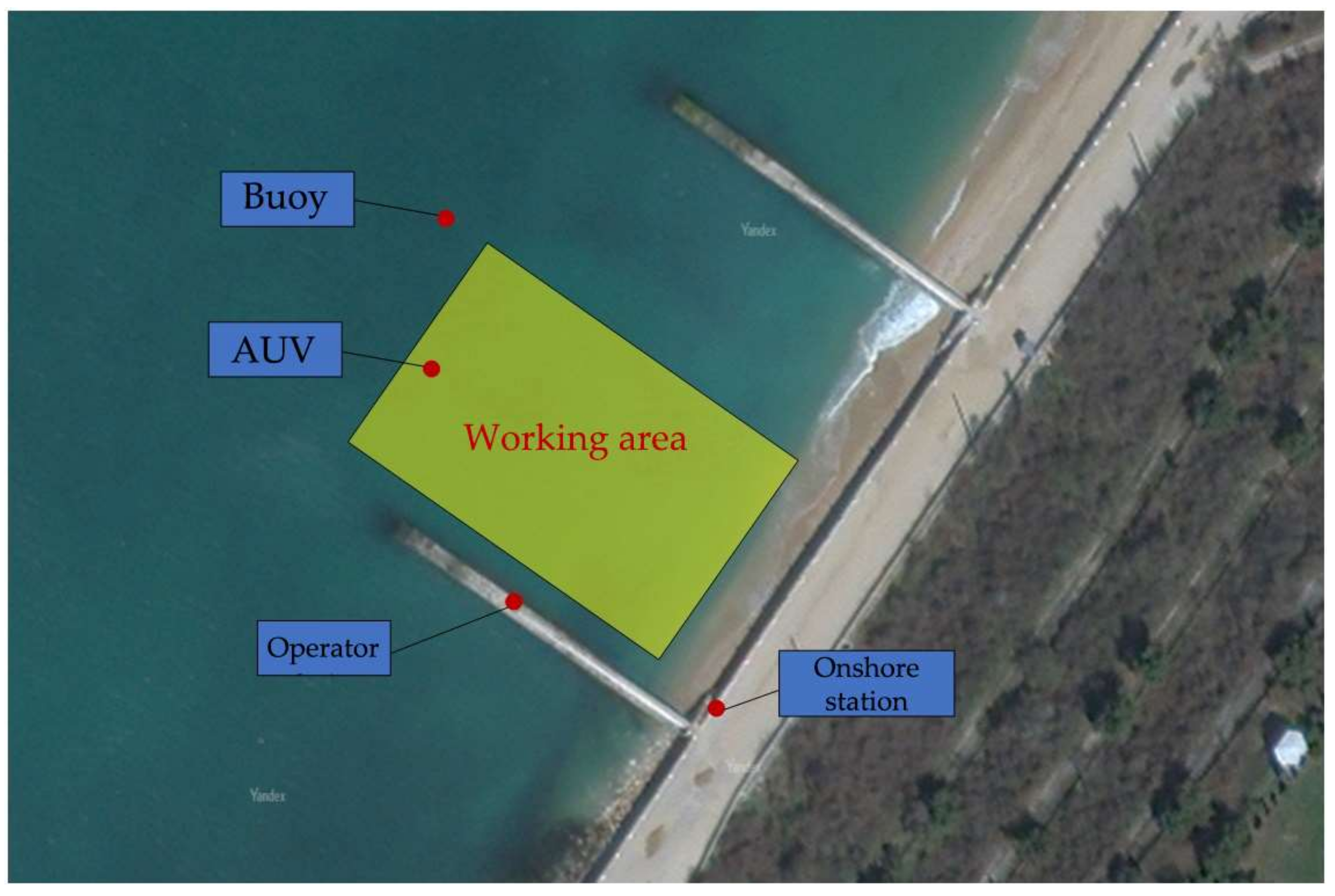
| Marini et al. [17]: MDPI(Marine Science and Engineering) | H2020 ENDURUNS project that describes a novel scientific and technological approach for prolonged underwater autonomous operations of seabed survey activities, either in the deep ocean or in coastal areas | To develop new applications in seafloor exploration and surveying | Monitoring systems, AUVs | Italy |
| Qin et al. [18]: IEEE Access | An autonomous underwater vehicle (AUV)-assisted hierarchical information acquisition system composed of a marine stationary sensor layer and an AUV motion layer | To involve new AUV path planning strategies | AUVs, sensor nodes, UWSNs | China |
| Lin et al. [19]: Chinese Journal of Mechanical Engineering | The future trend of the ocean observation systems with docking technology and sustained ocean energy | – | Ocean energy, AUVs, monitoring systems | China |
| Binnerts et al. [20]: IEEE: MTS/IEEE Kobe Techno-Oceans (OTO) | Development and demonstration of live data-streaming capability using an underwater acoustic communication link | It is planned to collect more representative channels at open sea for further testing and optimization | Acoustic communications | Netherlands |
| Lu et al. [21]: arXiv | The cognitive ocean network (CONet) is proposed and described | Using next-generation artificial intelligence technology | IoUT architectures | China |
| Saha [22]: IEEE Xplore | IoT-based automated fish farm aquaculture monitoring system | To develop a better way to capture images and use better image processing techniques to provide better results | Sensor nodes, ocean monitoring | Bangladesh |
| Li et al. [23]: Journal of the World Aquaculture Society | The major challenges and future trends of underwater object counting in aquaculture are discussed | To implement new counting tasks in aquaculture | Ocean monitoring | China |
| Wang et al. [27]: IEEE Communications Surveys & Tutorials | The concept of machine-type communication (MTC) for maritime IoT and its services, requirements, and challenges | To avoid the potential pitfalls in the development and standardization of maritime MTC technology | IoUT architectures, MTC | USA |
| Xia et al. [28]: IEEE Wireless Communications | An intelligent energy control scheme named the residence energy control system (RECoS) is proposed | To provide the sufficient attention of MIoT that it deserves in the 5G community | AI, ocean energy | China |
| Yang et al. [29]: IEEE Network | Explanation on how various AI methods can facilitate the operation of the parallel-network-driven maritime network | To speed up the AI methods | AI, IoUT architectures | China |
| Features | MIoT | IoT |
|---|---|---|
| Communication technologies | Most communications in the IoUT are based on acoustic links. | Mostly radio waves. |
| Tracking technologies | In the MIoT, things (usually fish) are tracked with different technologies: acoustic tags, radio tags, passive integrated transponders. | The IoT uses basic radio frequency identification (RFID) for tracking. |
| Battery recharge | Battery capacities are limited and it is difficult (sometimes impossible) to recharge or replace them. | As part of the IoT, replacing batteries is not difficult. |
| Energy-harvesting technologies | Piezoelectric energy harvesting can also be exploited in the IoUT. The IoUT also benefits from specific underwater energy-harvesting techniques such as ocean thermal energy. | Two of the most promising energy-harvesting technologies for IoT devices are solar energy and piezoelectric harvesting. |
| Network density | The IoUT is deemed to be sparse due to the cost and challenges associated with underwater deployment. | In the IoT, it is expected that a very large number of devices communicate if all the ‘things’ join the network. |
| Localization techniques | Terrestrial localization approaches: the localization with directional beacons (LDB) scheme. | The location of mobile devices in the IoT is afforded by global positioning system (GPS) satellites |
| Manufacturer | Modem | Bandwidth, kHz | Power Consumption, W | Range, km | Transmission Rate | Data Buffer | Maximal Depth |
| Water Linked | Modem M64 | 31–250 | 2, 6 | 0, 2 | 64 bps | 1 Mb | 200 m |
| Popoto Modem | S100RP | 20–40 | 20 | 1–2 | 80–9000 bps | N/A | 100 m |
| S1000RP | 20–40 | 20 | 1–4 | 80–10,240 bps | N/A | 2000 m | |
| UC&NL | uWave | 10–30 | 1–6 | 1 | 70 bps | 127 bytes | 300 m |
| uWAVE Max | 5–20 | 1–10 | 3 | 80 bps | 127 bytes | 400 m | |
| EvoLogics | S2C M 30/60 | 30–60 | 10 | 1 | 31.2 kbps | 1 Mb | 2000 m |
| 18/34H | 18–34 | 7 | 3, 5 | 13.9 kbps | 1 Mb | 2000 m | |
| 15/27 | 15–27 | 10 | 6 | 9.2 kbps | 1 Mb | 6000 m | |
| Develogic subsea systems | HAM. BASE | 40–65 | 100 | 1, 2 | 10 kbps | N/A | 6000 m |
| Types of Information Transfer | Pros | Cons |
|---|---|---|
| Acoustics | - Most commonly used technology; - Transmission of information over long distances (up to 20 km); - Transmission distance up to several kilometers; - Transmission power within tens of watts; - Antenna size ≈10 cm. | - Low transmission speed (up to a few kbps); - Long latency (seconds); - Bulky and power-consuming transmitters; - Damage to marine life; - Signal attenuation depends on transmission range and frequency (0.1–4 dB/km); - Wave propagation velocity: 1500 m/s; - The bandwidth depends on the transmission range: 1000 km < 1 kHz; 1–10 km ≈ 10 kHz; <100 m ≈ 100 kHz. - Transmission frequencies 10–15 kHz. |
| Radio | - Simple technology for air-to-water communication; - Flows and swirls of water practically do not produce disturbances; - There are no fixed location and directional rules; - Average close-range transmission speed of up to 100 mbps; - Wave propagation velocity ≈ 2.255 × 10⁸ m/s; - The bandwidth ≈ MHz; - Transmission frequencies 30-300 Hz (for direct connection) or MHz (for buoy-based systems); - Transmission power within a few megawatts or hundreds of watts (depending on distance). | - Small range; - Bulky and power-consuming transmitters; - Signal attenuation depends on frequency and water conductivity (3.5–5 dB/m); - Transmission distance up to 10 m; - Antenna size ≈ 50 cm. |
| Optics | - Fast data transfer speeds (up to Gbps); - Does not depend on the propagation speed in the liquid (the propagation speed is approximately equal to the speed of light); - Cheap and small transmitters; - Wave propagation velocity ≈ 2.255 × 10⁸ m/s; - The bandwidth ≈ 10–150 MHz; - Transmission frequencies 1012–1015 Hz; - Antenna size ≈ 10 cm; | - Problems with the air-to-water transition (due to refraction); - Visible light is quite strongly absorbed and scattered; - Short range; - Signal attenuation: 0.31 dB/m (in clear ocean) −11 dB/m (in muddy water); - Transmission distance ≈ 10–100 m; - Transmission power within a few megawatts. |
| Architecture | Layers | Principle | Topology |
| MIoT network architecture | 5 separate layers: application, transport, network, data link and physical layer | TCP/IP | Mesh |
| MIoT architecture based on a data transfer scenario | 3 layers: surface gateway, ROVs, source/destination/repeater nodes | Data transfer | Mesh |
| Functionality-based MIoT architecture | 3 layers: perception layer, network layer, application layer | Functionality | Mesh |
| Common MIoT-based system architectures | 5 levels [40]: perception and execution level, transmission level, preprocessing level, application level and business level | Machine-type communication | Mesh |
| The MIoT architecture, based on the environment of finding different devices and interaction objects | 3 layers: underwater sensor network, surface AD HOC network, Internet | The environment of finding different devices and interaction objects | Mesh |
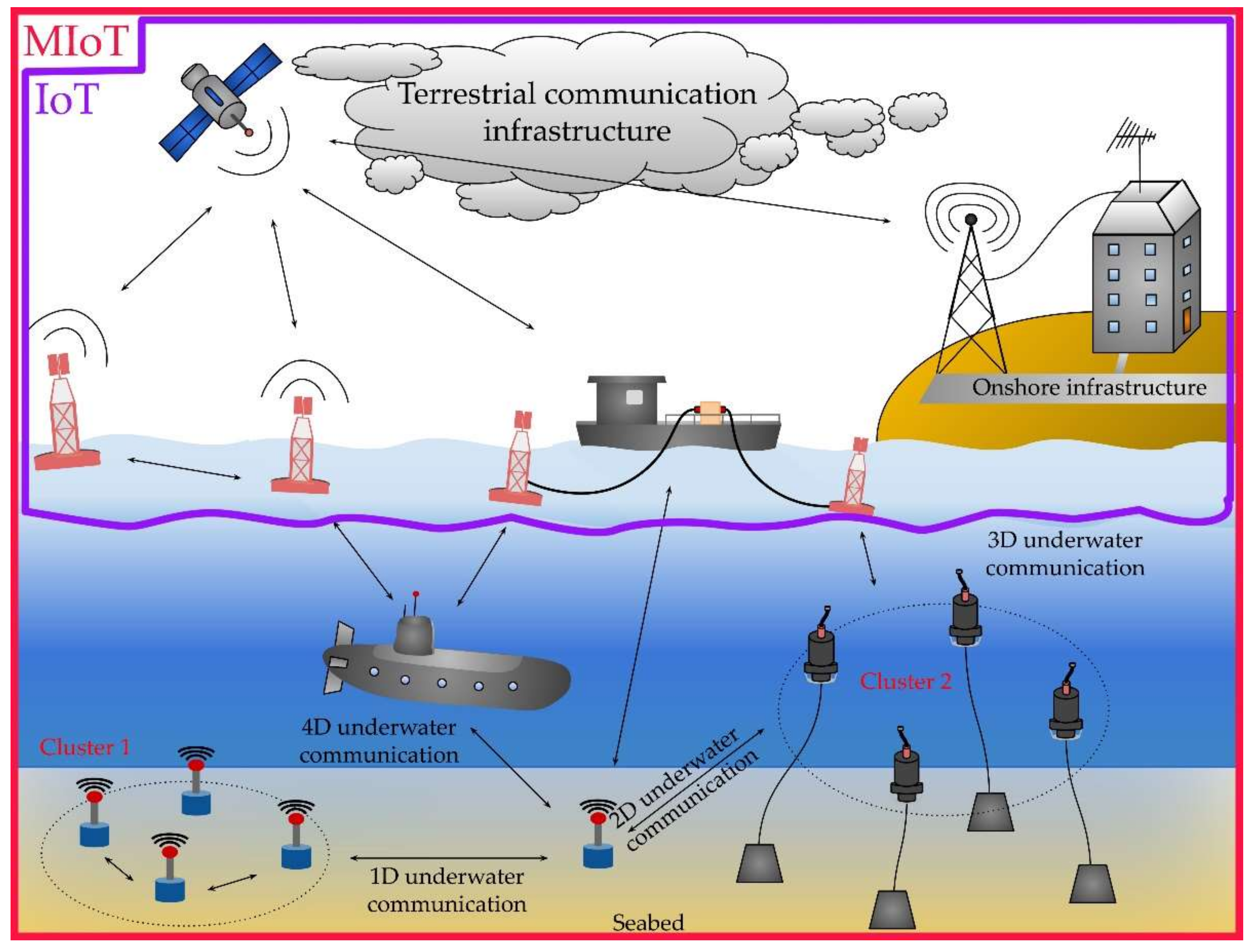
| 1D–4D | 4 layers: 1D, 2D, 3D, 4D | Functionality, TCP/IP | Mesh, 1D UWSN is star-shaped |
Publisher’s Note: MDPI stays neutral with regard to jurisdictional claims in published maps and institutional affiliations. |
© 2022 by the authors. Licensee MDPI, Basel, Switzerland. This article is an open access article distributed under the terms and conditions of the Creative Commons Attribution (CC BY) license (https://creativecommons.org/licenses/by/4.0/).
Share and Cite
Kabanov, A.; Kramar, V. Marine Internet of Things Platforms for Interoperability of Marine Robotic Agents: An Overview of Concepts and Architectures. J. Mar. Sci. Eng. 2022, 10, 1279. https://doi.org/10.3390/jmse10091279
Kabanov A, Kramar V. Marine Internet of Things Platforms for Interoperability of Marine Robotic Agents: An Overview of Concepts and Architectures. Journal of Marine Science and Engineering. 2022; 10(9):1279. https://doi.org/10.3390/jmse10091279
Chicago/Turabian StyleKabanov, Aleksey, and Vadim Kramar. 2022. "Marine Internet of Things Platforms for Interoperability of Marine Robotic Agents: An Overview of Concepts and Architectures" Journal of Marine Science and Engineering 10, no. 9: 1279. https://doi.org/10.3390/jmse10091279