1. Introduction
Air pollution from merchant ships can affect the air quality of different populations in many areas of the planet, and also affects the natural environment by contributing to acid rain. Hence, in 1997, MARPOL Annex VI was adopted, which regulates—among other things—sulfur oxides (SOx), nitrous oxides (NOx) and particulate matter emissions. Emission Control Areas (ECAs) were established, including some regions such as the Baltic Sea, the North Sea, some parts of the coasts of the United States and Canada, and some regions of the Caribbean Sea [
1,
2].
The latest revision of MARPOL Annex VI entered into force on 1 January 2020, limiting the possible emission of sulfur from 3.50% to 0.50% mass by mass, in merchant ships operating outside designated Emission Control Areas (ECAs) [
2,
3].
This emission restriction is good news for the environment; however, it imposes an economic cost for shipping companies, as it is now impossible to use the much cheaper heavy fuels oil (HFO), which is much more harmful for the environment. All merchant ships worldwide, that belong to the International Maritime Organization (OMI), must, therefore, now either use low sulfur fuel oil (LSFO) or install scrubbers in their ships to clean the HFO. In the maritime world, it has been established that operating with LSFO is preferable and less expensive than operating with the installation of scrubber systems [
4].
Along with pollution, another of the key objectives set by the IMO is the efficient use of energy in propulsion merchant vessels, thus, it has established new indicators such as the energy efficiency existing ship index (EEXI), and the carbon intensity indicator (CII) [
5,
6]. At this point, it is important to note that good maintenance strategies contribute to energy efficiency.
In this sense, the cleanliness of the oil used in lubrication is essential to achieve a better use of energy and reduce losses in marine engines. Lubricating oils are the life-blood of the combustion engine, and their proper cleaning is vital for their efficient operation. The lubricants used in ships’ internal combustion engines reduce friction losses, which are significant, being in the order of 35 to 45% in piston systems. Therefore, it is essential to keep the oil as clean as possible [
7,
8,
9].
Similarly, impurities in oils lead to an increase in friction in the parts, which clearly deteriorates many engine systems. The biggest contaminants in motor oils are water and fuel, which can accumulate in lubricants and cause problems such as reducing the viscosity of the lubricant, accelerating the formation of sludge in the engines, and changing the oxidation properties of the lubricating oil, etc. Therefore, oil cleanliness is of great interest [
10,
11].
It is well known that there are filtration systems on ships intended for the cleaning of lube oils for diesel engines. In particular, the centrifuge separator systems for oil lubricants allow the oil to be cleaned both of solid particles and the possible existence of water and sludge [
12].
From all of the above, it can be deduced that it is essential to maintain lube oil purifiers in good condition at all times. Therefore, ongoing research is very important to develop techniques that allow a fault diagnosis to be obtained as soon as possible [
13].
To detect changes in the dynamic behavior of a rotating machine, in order to predict or detect faults, it is common to analyze the vibratory signals that are produced during operation, because machine vibration response is sensitive to any structural change [
14] and is commonly used to detect sustainable changes in the rotating frequency and its harmonics [
15]. Condition monitoring through vibration analysis is becoming more and more common in marine fuel oil separator systems and pipes [
12,
16,
17,
18].
It is possible to obtain, and more easily interpret, time and frequency information from vibratory signals by using processing tools. When frequency information is sufficient to allow a diagnosis, it is common to use fast fourier transform (FFT) or power spectral density (PSD) [
19]. However, when small changes are sought, frequency information is not enough to reach a diagnosis, and for this reason, other tools such as wavelet transform (WT) are used [
20], since WT obtains both time and frequency information and is a powerful tool for feature extraction [
21]. In particular, wavelet packet transform (WPT) has increasingly been used in many works [
22], since the analyzed frequency range is divided into smaller frequency ranges of the same resolution. When a machine is being monitored, a large amount of information is obtained in real time, so it is interesting to obtain the features or patterns to be monitored, in order to detect changes in different operating conditions.
Different parameters must be selected when wavelet-based techniques are applied. One of these parameters is called ‘mother wavelet’, which is the function to which the study signal is compared, therefore, a good selection is required to obtain good patterns [
23]. Many studies have chosen this function based on experience, such as [
24], while other studies have chosen the function based on the shape similarity of the fault under consideration, to the mother wavelet [
21]. This is not feasible from the point of view of energy savings, since it is possible to use the most appropriate parameters to obtain more accurate, faster and more reliable results in order to monitor patterns more efficiently during machine operation. Therefore, currently, methodologies are being proposed for the selection of the optimal mother wavelet for each case and condition [
25]. Although the WPT has been used in several studies to detect different defects in different mechanical components and rotating machines [
24,
26], no study has yet focused on finding the optimal mother wavelet to extract patterns that change according to the number of operating hours in a faster, more reliable, and efficient way, in purifiers of marine lube oils. For this reason, in this work, a methodology to select the best mother wavelet and the patterns to monitor the state of centrifugal oil lubricant separators systems, was carried out. An aspect of interest for the diagnosis of these systems is to determine whether the different mechanical systems work properly. In particular, the axis of rotation, as well as the different types of bearings, must be monitored to avoid failures that ultimately result in catastrophic failures for the whole system. Therefore, this study focused on the measurement of vibrations, and specifically, their pre-processing, the latter being the main objective of the research. The methodology considered the energy variation (DEV) of two conditions: after performing maintenance, and after several hours of operation. The computation time and the success rate of a linear support vector machine (SVM) model was used in a supervised intelligent model in which both conditions were distinguished. With the selected mother wavelet, the energy variation between the two conditions was analyzed by means of the frequencies corresponding to the motor speed and its first harmonics, as well as the bowl speed.
The paper is organized as follows. In
Section 2, the centrifugal oil separators used in the experiments are described. The experimental set-up for the measurement of vibrations is depicted in
Section 3.
Section 4 describes the processing system used to select the optimal function to conduct the wavelet analysis. In
Section 5, the obtained results are shown and the selection of the best patterns to characterize the machine condition are presented, leading to the conclusions in
Section 6.
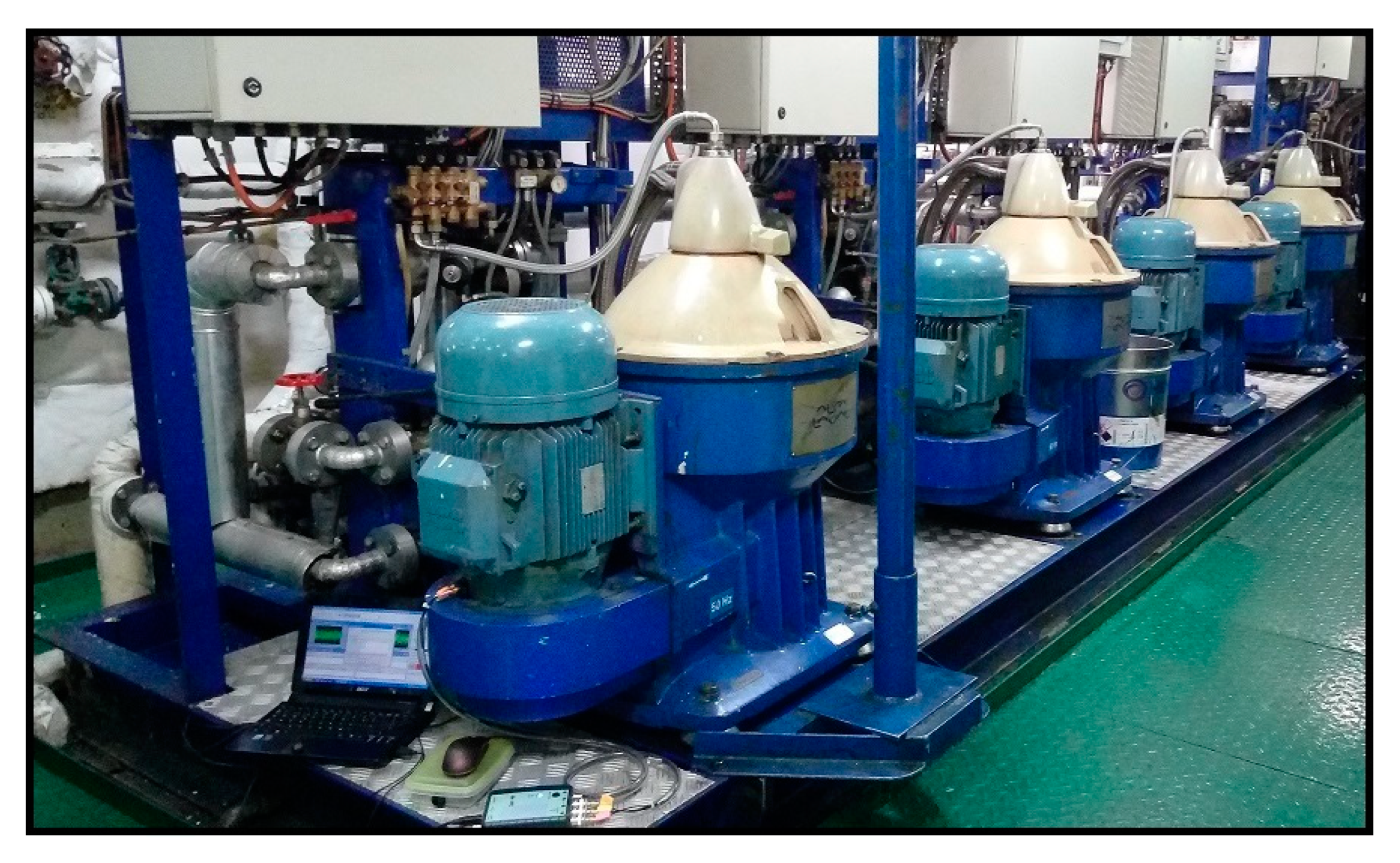
2. Oil Cleaning, Centrifugal Separators
A centrifugal separator is a device designed to clean lubricating oil and fuel oil by centrifugation, based on the differences in density (oil–water or fuel oil–water). Currently, the main purpose of separator systems or centrifugal separators in merchant ships is the cleaning of lubricating oils, considerably reducing their use in cleaning heavy fuel oil (HFO) due to the increased consumption of low sulfur fuel oil (LSFO) [
1,
2,
27].
The monitoring of mechanical processes has always been a challenge in the sea industry. The centrifugal separator for cleaning lube oils for diesel marine engines is a complex mechanical system, as much for its operation as for its maintenance. These on-board mechanical systems have minimum, indirect equipment monitoring; only a speed sensor, and perhaps an imbalance sensor and an interlocking switch. This insufficient vigilance can lead to serious and costly breakages, as the state of the system cannot be accurately diagnosed [
12,
28].
In the centrifugation process, large forces are generated due to kinetic energy, and undesired vibrations can occur in the system. These vibrations can occur for several reasons, for example, unbalanced rotating parts can lead to catastrophic machine failure. In some cases, extreme vibration causes the separator to stop operating, which can be caused by a damaged transmission, worn bearings, a broken drive belt, or broken spring, etc. In a high percentage of cases, system damage is caused, being impossible to avoid. These abnormal vibrations in the separator systems are not displayed on the control panel [
12,
16,
29,
30].
Preventative maintenance is carried out on centrifugal separators in the maritime industry, based on the recommendations of the manufacturers. The implementation of predictive maintenance in these systems may be more appropriate since it would allow efficient control of the behavior of the mechanical variables of the separator during its operation, the diagnosis of any failure, and the planning of maintenance [
12].
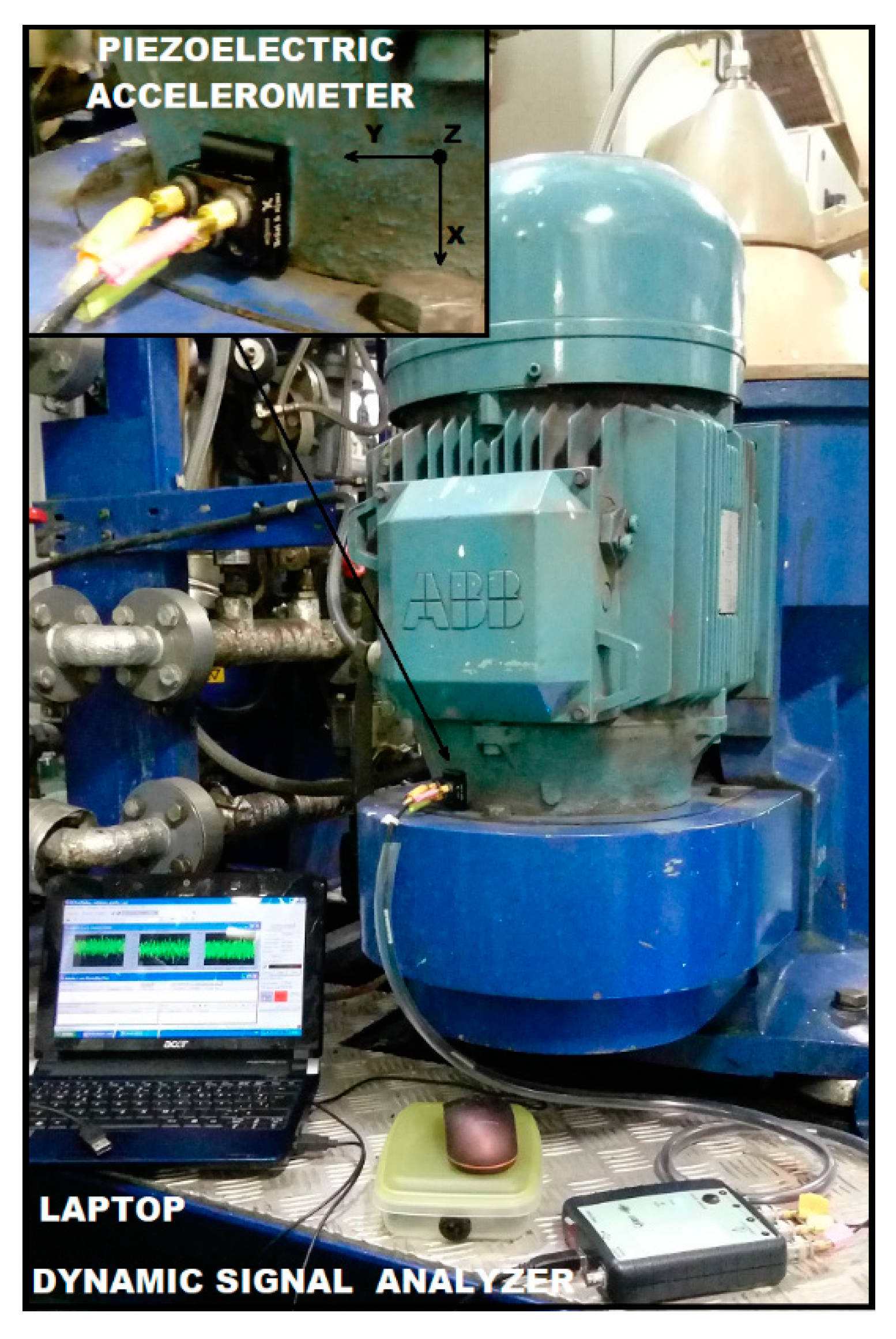
Preventive maintenance, and in particular, the use of a condition monitoring system, is critical for the primary identification and elimination of undesired vibrations. For this reason, it is crucial to incorporate vibration sensors in separator systems, together with suitable algorithms to detect changes in operating conditions [
12].
Vibration analysis using mathematical models, in this case, soft computing techniques, allows extraction of the representative characteristics of the centrifuges, which could be related to the useful life of their parts and could indicate whether a maintenance operation is required, or not. In the whole process of mathematical analysis of vibrations, one of the most important steps is the pre-processing of the signal, which is analyzed in this research.
4. Data Preprocessing
Data preprocessing was performed by analyzing the time-frequency domain using wavelet packet transform (WPT), since this tool is very useful for patterns extraction. WPT and the proposed methodology for the mother wavelet selection are described below.
4.1. Wavelet Transform
Wavelet transform (WT) is a processing tool with the ability to extract both temporal and spectral information. To apply it, it is necessary to choose a function called mother wavelet,
, described by Equation (1), which is then compared with the study signal by calculating the correlation coefficients that depend on the scale (
) and translation
) of the wavelet function [
31].
This tool can be applied continuously (continuous wavelet transform—CWT) or discretely via filters (discrete wavelet transform—DWT). In the latter case, signals are decomposed by a low-pass filter and a high-pass filter, in order to obtain the approximate (A) and detailed (D) information, respectively [
31].
The tool which was applied in this work was wavelet packet transform (WPT), which applies the DWT recursively up to a level of decomposition, k, set by the user. The analyzed frequency is divided into frequency ranges of the same resolution, called packets, which are determined by 2k. In this way, the correlation coefficients are calculated for each packet.
As a large amount of data are obtained, the most appropriate and common method to reduce the information without reducing the performance of the system is to calculate the energy of each packet, so that the information can be easier to monitor.
In this work, the selection of the optimal mother wavelet was performed with a decomposition level of 3, obtaining 8 packets of 160 Hz each. Then, in order to find patterns that best differentiated both conditions (C1 and C2), another WPT analysis was performed with the selected mother wavelet.
4.2. Methodology for the Selection of the Mother Wavelet
In order to find patterns that change substantially when marine oil separation systems, henceforth called ’MOSS’, have been working for several hours, WPT was applied. As was commented previously, the selection of the mother wavelet (MW) is normally performed based on experience, without prior analysis, which is a disadvantage since the results can vary considerably using one or the other. The optimal selection of the MW is vital to perform a more reliable and faster analysis. For this reason, the selection was carried out based on: computation time; greater differentiation of initial–final conditions, for which a parameter has been created; and the success rate of an intelligent classification system, which can determine which mother wavelet would give fewer false alarms of the machine’s condition prediction.
There are many different families of MW, each with their own properties. One of the most important is the number of vanishing moments [
25], which is directly related to the order of the family (N). In this work, the families Daubechies (db), Symlets (sym) and Coiflets (coif) were selected to carry out the methodology, as they are applicable for DWT tools. In addition, within these families, different orders of the mother wavelet can be chosen.
In order to establish a comparative study among the three families, and as the maximum order of the Coiflets family is 5 (which is equivalent to 10 vanishing moments), the other families were also analyzed up to 10 vanishing moments. On the other hand, it has been proved that the results tend to converge as the order of the mother wavelet increases, thus, increasing the order does not imply a large improvement in the results and requires much more computation time [
25].
The steps for the selection of the optimal mother wavelet are the following:
Application of the WPT using each mother wavelet (dbN, coifN, symN) for a decomposition level of 3, obtaining 8 packets and calculation of the energy of each packet. This will be performed for each MOSS and for each measuring axis;
Calculation of the DEV value with Equation (2), where
is the number of packets, which is 8 in this case;
is the mean energy of packet
for the measurements taken after hours of the MOSS working (C2), hereinafter referred to as final measurements; and
is the mean energy of packet
for the measurements taken after carrying out the maintenance (C1), hereinafter referred to as initial measurements. This parameter is a way of measuring the difference in energy between the initial and final measurements, and is sought to be as high as possible, so that there is greater distinction;
Calculation of the DEV variation (DEV (%)) using Equation (3). This calculates the difference of the DEV value between the results of a mother wavelet (
and the mother wavelet with the highest analyzed order of its family
. For example, the DEV value of each Daubechies from orders 1 to 9 are compared with the DEV value obtained with Daubechies 10. With this value, a variation of less than 2% is sought on all axes, so those mother wavelets with a greater variation will be discarded;
For the mother wavelets that meet the last criterion, the energy values of the packets are entered into a supervised intelligent classification system, in which two classes are differentiated: the first measurements, and the second measurements. The validation type used is cross-validation, which protects against overfitting by portioning the data set into folds (50 in this case, which is the maximum possible) and estimating accuracy on each fold.
Using a linear support vector machines model, it is possible to calculate the line that best separates both classes, and calculates the success rate. In this way, the mother wavelet with the highest success rate is the one which is selected. In the case that several mother wavelets have the same value, the one with the lower order will be selected, and if there are some mother wavelets with the same order, the one with the least model computation time will be selected, since a continuous monitoring system based on alarms can be established and is more suitable and safer if it takes less time to calculate.
5. Results and Pattern Extraction
In this section, the application of the methodology was carried out. The optimal mother wavelet was selected, and then the differentiating patterns were selected.
5.1. Wavelet Mother Selection
The methodology proposed in the previous section was applied to the four tested MOSS. In this section, the results of MOSS 1 will be shown in detail, and a summary of the most conclusive results of the remaining MOSS will be presented.
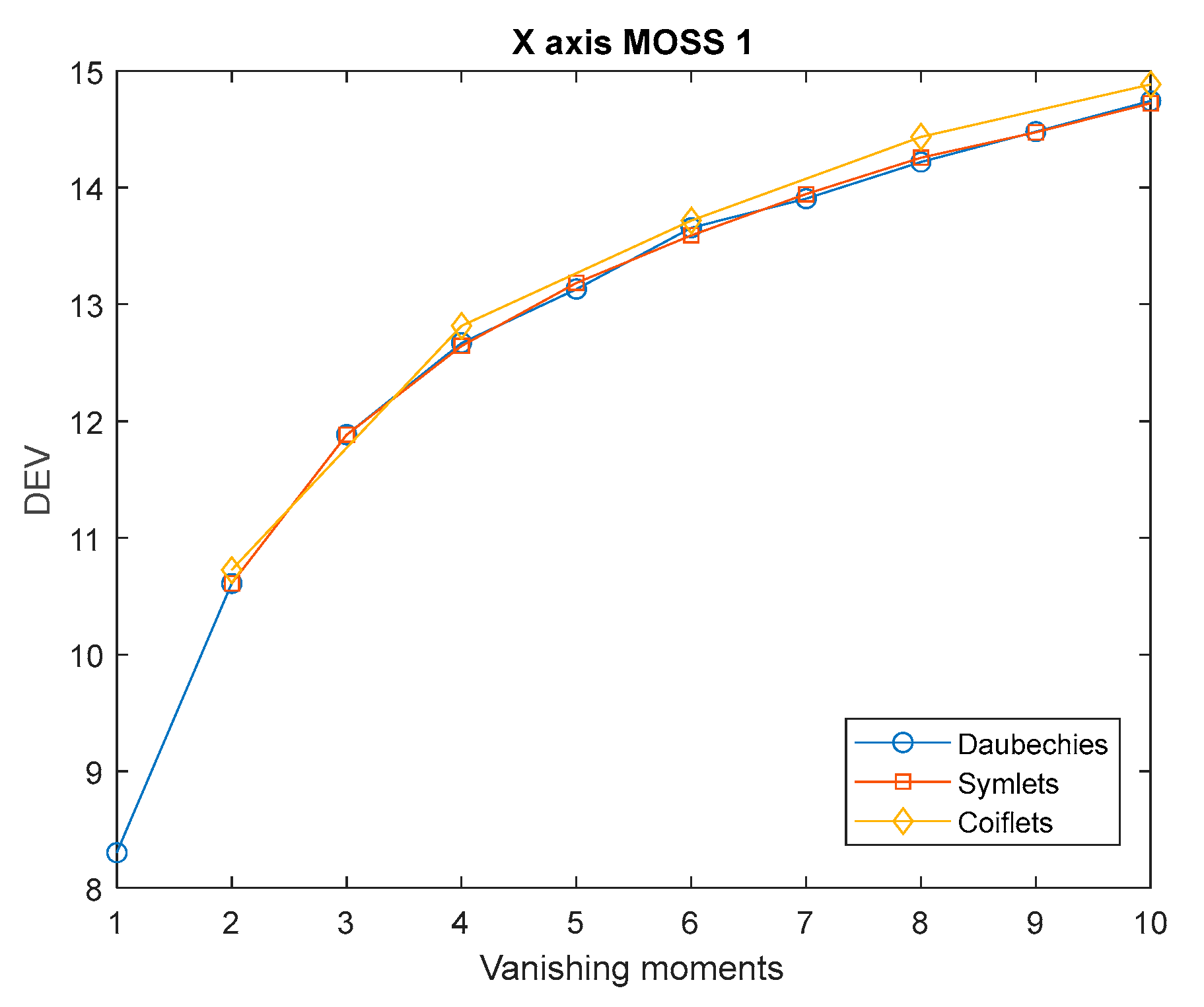
Figure 4 shows that, once the DEV values were calculated following the steps of the methodology, the DEV evolution on axis X can be seen as a function of the number of vanishing moments for the three MW families. The DEV value tended to stabilize as the order increased for all families, which is why the DEV variation, with respect to the DEV of higher order, was calculated. The same trend was observed in all MOSS and axes, but with different scales. This coincided with the observation of previous work [
25], in which a methodology for the selection of the mother wavelet was proposed for shaft crack detection, as it was based on the same parameters.
The DEV (%) was then calculated. The mother wavelets with a variation of less than 2% on all axes were then preselected.
The DEV variation values are listed in
Table 2. According to the criterion, db9 and sym9 were preselected and are shown in the same table; the Coiflets function is not shown, since it was not selected. In can be concluded that the X axis determined the selection of the optimal MW.
The results for each preselected mother wavelets were then entered into a classification system, and the success rate was calculated using a linear SVM model (
Table 3).
According to the criteria, mother wavelet sym9 was optimal for MOSS 1, as when there is the same success rate, the MW that requires less computation time is selected. The success rate in this case was the same. This may be due to the small amount of data that were entered into the classification system, and because the order of the MW was the same. The same procedure was carried out for the rest of the MOSS, obtaining sym9 for MOSS 2, db9 for MOSS 3, and db7 for MOSS 4. The difference in results was due to the fact that each machine had different hours of operation, so it was considered as normal that MOSS 4, which had been operating for more hours, needed a mother wavelet of lower order, since differences will be more easily seen between the first measurements (C1) and the second (C2). However, since all measurements were from the same machine, the ideal is to choose one mother wavelet for all, therefore, sym9 was selected, since it was the one that was valid until the final criterion of the methodology, in all cases (
Table 4).
5.2. Patterns Extraction
Once the mother wavelet was selected, WPT was then applied with a higher decomposition level, in order to extract patterns that identified the condition, as it is common in rotating machines to analyze the harmonics of the rotation frequency. In this case, a decomposition level of 6 was used, because the frequency resolution of each packet (20 Hz) ensured that the harmonics of the rotation frequency were included, and it was enough to detect sustainable changes in a short computation time.
In this way, only the low frequency part of the signal (up to 200 Hz) was analyzed, because in a previous work [
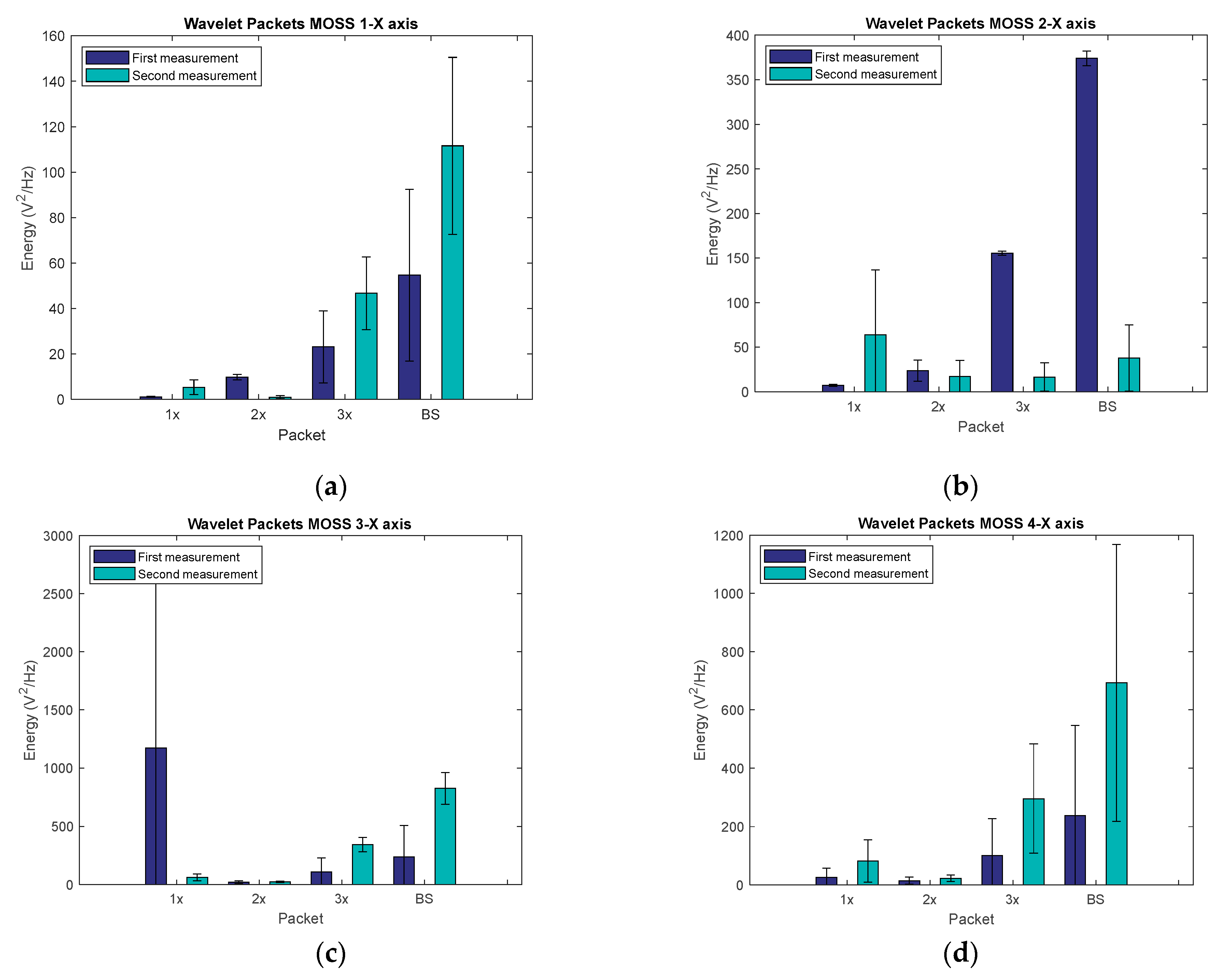
12], changes at motor speed (represented as the first three harmonics of the rotation frequency 1x, 2x, 3x) and bowl speed (BS) were observed. For this reason, packets corresponding to the first three harmonics of the motor speed and the packet corresponding to the bowl speed were analyzed, showing the energy variation between the first measurements (C1) and the second measurements (C2). In
Figure 5, the mean energy and standard deviation of the mentioned packets are shown for both conditions C1 and C2, for each MOSS and on X axis (axial), where it can be seen that the results are clearer.
In MOSS 1, it was observed that the packet corresponding to the motor speed increased its energy, as well as the third harmonic and the bowl speed (BS). In MOSS 2, only the packet corresponding to the motor speed increased its energy with working hours.
In MOSS 3, it was observed that the second and third harmonic, and the bowl speed, increased their energy with working hours. The energy of the packet that corresponded to the motor speed did not increase in this case, which could be due to the high standard deviation of the measurements taken on the X axis.
In MOSS 4 all packets increased their energy with working hours, which occurred on all axes.
It can be concluded that the energy of the packet than included motor speed was a good pattern that changed its energy with working hours and on all axes. However, it was shown that the more working hours, the more that frequencies increased the energy on all axes, as seen for MOSS 3 and 4.
As an example, the increase in relative energy, between the first and the second conditions of the packet corresponding to the motor speed for MOSS 4 on the X axis, was calculated using symlet 9, which was the one selected by applying the methodology, obtaining an energy increase of 225.42% compared with an increase of 216.95% obtained with Daubechies 6, which has been used in many studies based on experience [
24,
26,
32]. As can be seen, using the optimal mother wavelet allows obtainment of the maximum increment in energy in the shortest possible time, which was the objective of the proposed methodology, since in this way, it is easier and more reliable to establish a threshold to determine the operating hours and condition of the machine, which will be analyzed in future work.
6. Conclusions
In this work, a methodology for the optimal selection of the mother wavelet function to perform a WPT analysis was proposed. This methodology was developed with the intention of maximizing the differentiation of energy (DEV) between vibratory signals taken after performing maintenance, and signals taken after several hours of work in different marine oil separation systems (MOSS), considering a low computation time and the success rate of a supervised intelligent classification system using a linear SVM model. In this sense, the methodology, here applied, allowed the choice of the most promising pattern to study the wear or malfunctioning of centrifugal oil lubricant separators systems, either by analyzing the value of the pattern during operation, or by means of an intelligent diagnostic system. The result showed that packets obtained with a symlet 9 mother wavelet and with a decomposition level of 6 allowed monitoring of the evolution of the energy of the motor speed harmonics and the bowl speed. In this case, it was observed that the energy of the packages related to these critical frequencies increased over time. Hence, in this paper, a well adapted methodology for the case of determining the different states of working of a particular group of centrifugal oil lubricant separators systems has been chosen. The achieved results were satisfactory, showing this methodology to be an adequate selection.
The same methodology could be applied to other systems in order to achieve similar results, improving the algorithms of working state identification.


