1. Introduction
As we know, the ocean is rich in medical resources, mineral resources, marine living resources and so on. To facilitate the investigation of the ocean, a large variety of underwater robots such as the Autonomous Underwater Vehicle (AUV) have been designed [
1,
2]. The AUV is one kind of intelligent marine robot with many advantages such as strong autonomy and high maneuverability, so it has gradually become an important platform to perform various underwater tasks. Nowadays, the AUV has a wide range of applications in the ocean, such as sea rescue, search range, pipeline inspection and other fields [
3,
4]. Since conventional AUVs are of torpedo-style shapes, they have great defects such as an underactuated system and excessive turning radius. Many researchers have devoted themselves to new and different types of underwater vehicles, and some underwater robots with new architectures have been developed recently [
5,
6,
7]. A new type Autonomous Underwater Helicopter (AUH), which has a unique dish shape and can realize “four arbitrary” functions of full turn, fixed hover, precise landing, and free landing, was designed by Zhejiang University [
5,
6]. In addition, a new type of underwater snake robot, which mimics the motion of eels, was used to test a set-based guidance strategy for path-following with obstacle avoidance [
7]. New multilink gliding robotic fish can swim flexibly and glide energy efficiently in three dimensions [
8,
9]. To summarize, underwater vehicles with new structures can make up for the defects of the torpedo AUV. In this paper, we design a new-style AUV named the underwater quadrocopter vehicle to verify the obstacle avoidance mechanism.
Due to complex and changeable underwater environments, autonomous underwater robots must be able to avoid underwater obstacles such as cliffs, wrecks and seafloor fluctuation [
10]. The primary goal of obstacle avoidance is to maintain underwater robot safety in a mostly unknown environment through fully autonomous operation [
11]. Increasing the autonomy of AUVs has the potential to make underwater operations safer, more efficient, cost-effective, and environmentally friendly. Unfortunately, although there are many research studies on obstacle avoidance strategies for unmanned aerial vehicles, obstacle avoidance research on autonomous underwater robots is still not common and mature. At present, underwater obstacle detection mainly depends on sonar and underwater vision. Due to the special working environment, sonar is traditionally the primary sensor for underwater robots [
12,
13,
14]. Underwater sonar can provide low resolution images of underwater obstacles to obtain estimations of an obstacle’s position and movement trend, but they are inaccurate.
Petillot et al. [
12] propose a novel obstacle avoidance and path planning framework for underwater vehicles based on multi-beam forward looking sonar. Braginsky et al. [
13] provide extensive simulation and experimental results to demonstrate that the proposed three horizontal and one vertical obstacle avoidance approaches enable AUVs to navigate safely through obstacles. Belcher et al. [
14] use a Dual-Frequency Identification Sonar (DIDSON) as an obstacle avoidance sonar to perform autonomous obstacle identification.
On the other hand, there are some obstacle avoidance applications based on underwater machine vision [
15,
16,
17,
18]. A vision-based obstacle detection technique using optical flow is proposed for collision avoidance of Autonomous Quadrotor Navigation in [
15]. Barrett et al. [
16] apply structured light laser imaging into underwater obstacle avoidance and navigation. Leonardi et al. [
17] provide a proof of concept regarding a series of experiments investigating stereo vision for underwater obstacle avoidance and position estimation. Drews et al. [
18] propose a new vision-based obstacle avoidance strategy using the Underwater Dark Channel Prior (UDCP) algorithm that can be applied to any underwater robot with a simple monocular camera and minimal on-board processing capabilities. Evans et al. [
19] outline the sonar and video sensor processing techniques used for real-time control of the Intervention-AUV to perform tracking and 3D pose reconstruction. Xue et al. [
20] propose a bio-inspired collision risk-assessment method for ensuring safe USV operation based on stereo vision.
Moreover, an underwater obstacle avoidance mechanism is often studied in tandem with path planning [
21,
22,
23,
24,
25]. Path planning for ambulatory data gathering is discussed in [
21], and an autonomous underwater vehicle traverses only location points in the constructed covering set with a hierarchical grid-based obstacle avoidance strategy. To solve the problem of autonomous obstacle avoidance in trajectory tracking, the model predictive control algorithm is applied to design an obstacle avoidance controller from the point of view of trajectory re-planning [
22]. On the premise of realizing dynamic target obstacle avoidance, an adaptive generic model controller based on Radial Basis Function (RBF) neural networks is provided in [
23]. A novel three-dimensional obstacle avoidance algorithm for an autonomous underwater robot with a sphere cross-section method is proposed in our previous work [
24]. Moreover, we utilize ocean current characteristics simplified as a stream-function to design an optimal 3D trajectory with an obstacle avoidance function [
25]. In conclusion, these obstacle-avoidance-based path planning methods consider only path design based on prior-known obstacles but ignore how to obtain the obstacle’s shape and the distance from the underwater robots. It is worth emphasizing that, to the best of our knowledge, the location and shape of an underwater obstacle are assumed to be obtained previously in almost all obstacle avoidance path design algorithms.
In this paper, we propose a new type of underwater robot, which is equipped with an underwater binocular vision system on the robot’s head, to verify the obstacle avoidance effect. The robot is named the underwater quadrocopter vehicle. Due to the impact of long-time water flow, convex underwater obstacles will become smooth and round gradually, so it is assumed that most underwater obstacles can be enveloped by particular spheres with various radii. Herein, for the sake of simplicity, we only discuss certain application scenarios with only spherical obstacles in this paper. Moreover, an underwater binocular-vision-based obstacle positioning algorithm is proposed to measure a spherical obstacle’s shape and its distance apart from the UQV. Subsequently, practical pool experiments verify the performance of proposed binocular vision system. Finally, simple semicircle-curve-based trajectory planning for the UQV is introduced to avoid multiple spherical obstacles effectively.
The main contributions of this paper are:
- (1)
A novel binocular-vision-based obstacle ranging and recognition method for underwater applications is proposed in this paper, and the radii of spherical obstacles and the distance between them are calculated and applied to design the obstacle avoidance trajectory.
- (2)
Different from existing methods, this paper not only considers an obstacle-avoidance-based path planning algorithm, but also studies an underwater obstacle recognition and processing method simultaneously.
- (3)
This paper proposes a new type of underwater vehicle named the underwater quadrocopter vehicle, and its theoretical kinematic and dynamic model is investigated to verify full degree of freedom of movement and obstacle avoidance ability.
The rest of this paper is organized as follows.
Section 2 describes the detailed kinematic and dynamic model for the proposed underwater quadrocopter vehicle.
Section 3 proposes the underwater binocular-vision-based obstacle positioning method in detail.
Section 4 illustrates spherical-obstacle-avoidance-based continuous path design method.
Section 5 shows simulation results and the actual pool test of the proposed obstacle avoidance based path design.
Section 6 presents the conclusion of this paper.
2. The Underwater Quadrocopter Vehicle Model
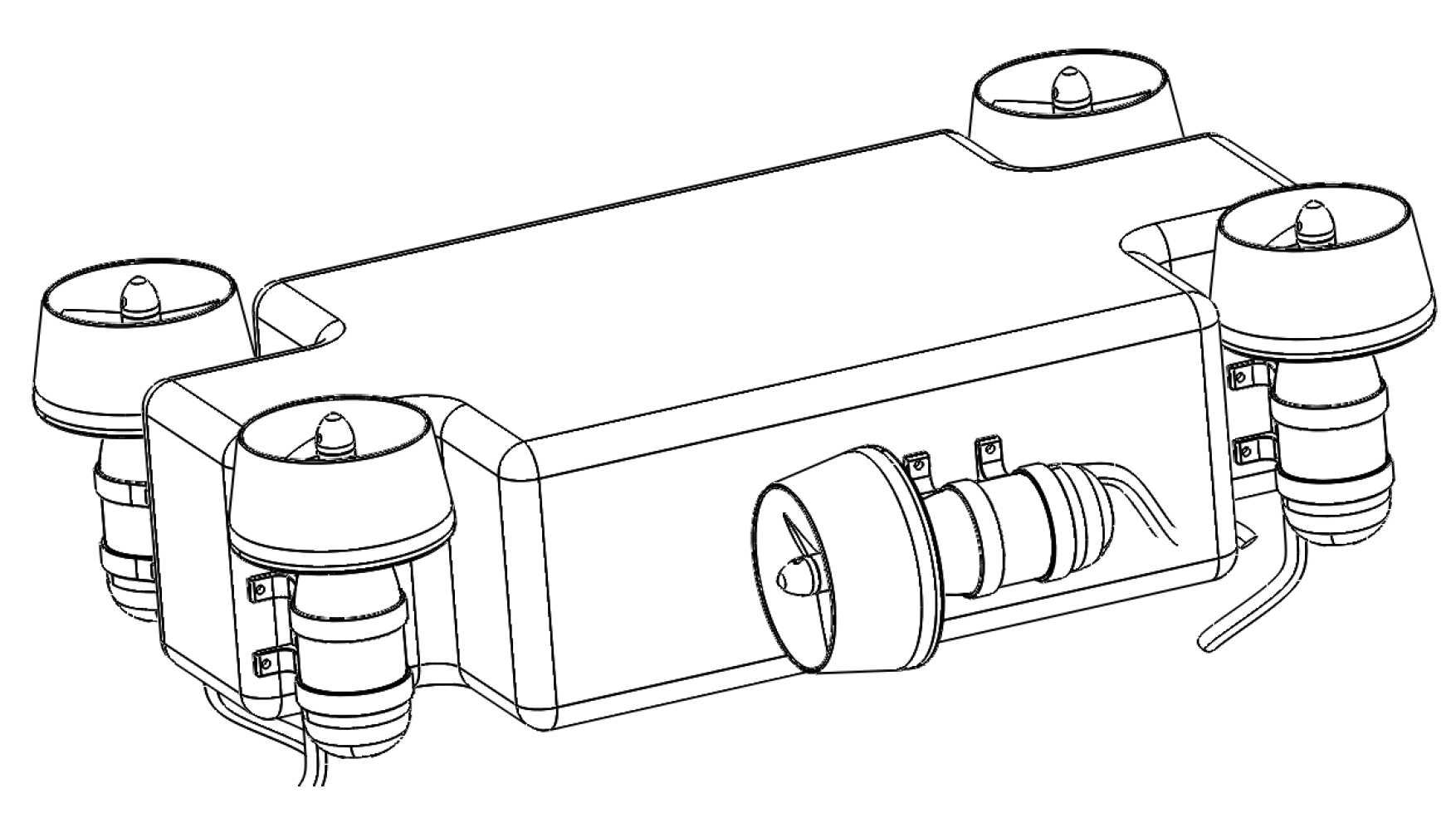
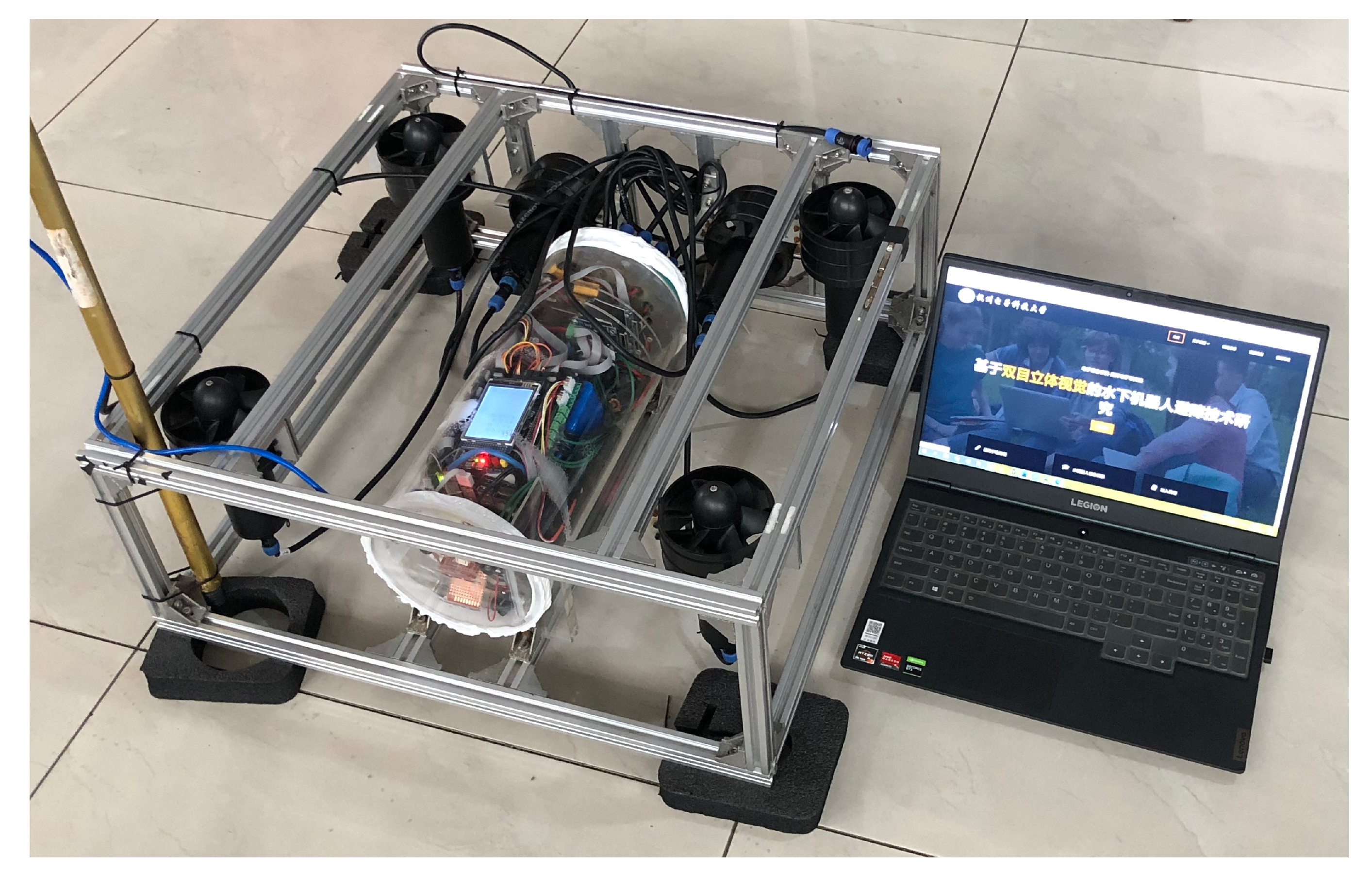
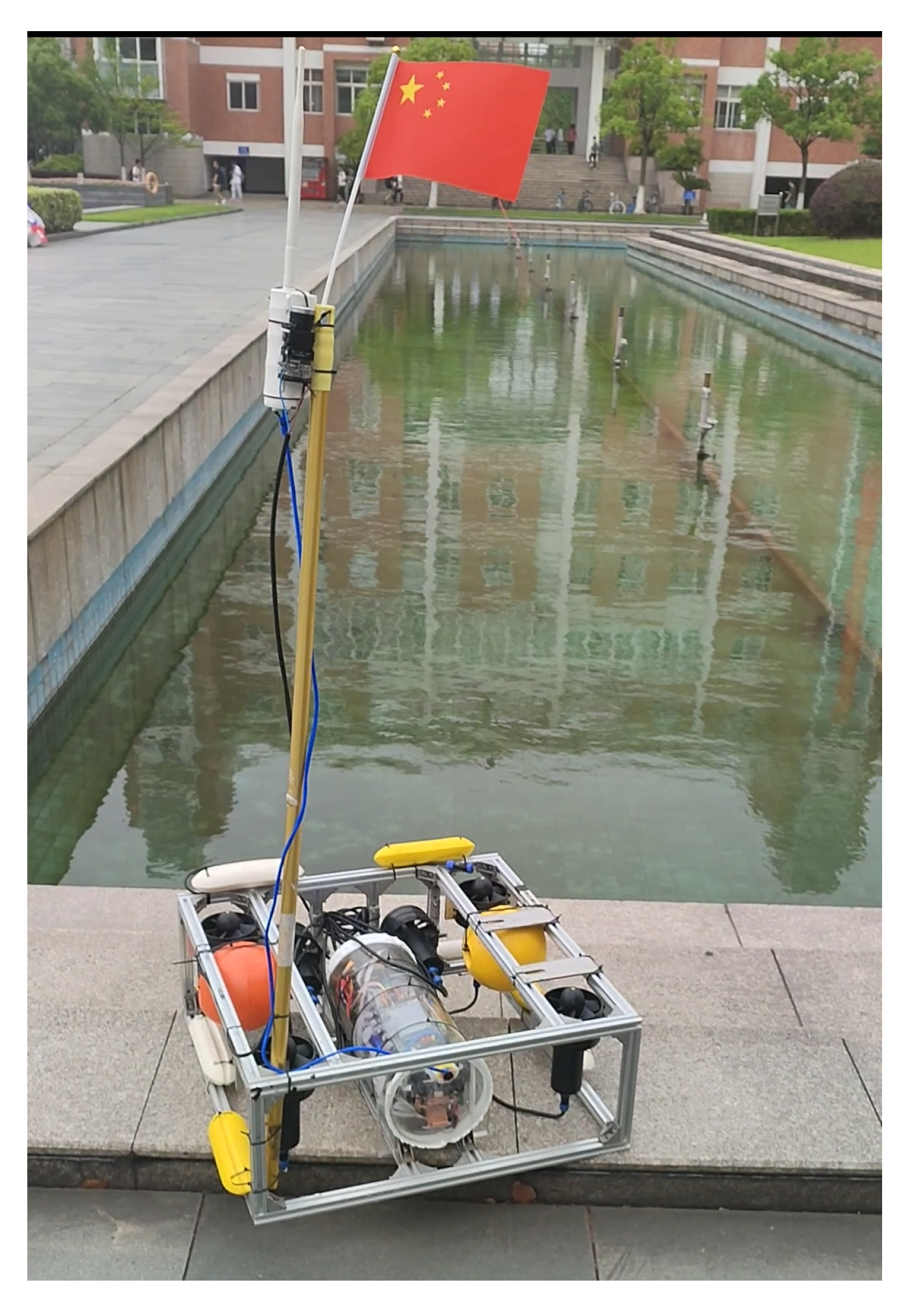
Different from a traditional torpedo-shaped AUV with one thruster and several steering engines, the well-designed UQV is equipped with four rotors on the vertical direction of the robotic body and two propellers equipped on the two sides of the robotic body. The mechanical structure of our self-made UQV is described in
Figure 1. As we know, traditional torpedo-shaped AUVs often have inherent defects such as large turning radii and are unable to move vertically. However, the proposed UQV has a much smaller radius of gyration and can even turn in place with any turning radius. In conclusion, due to its perfect ability of full freedom underwater movements, the proposed UQV can perform cruise control, fixed depth hover, vertical floating and diving perfectly.
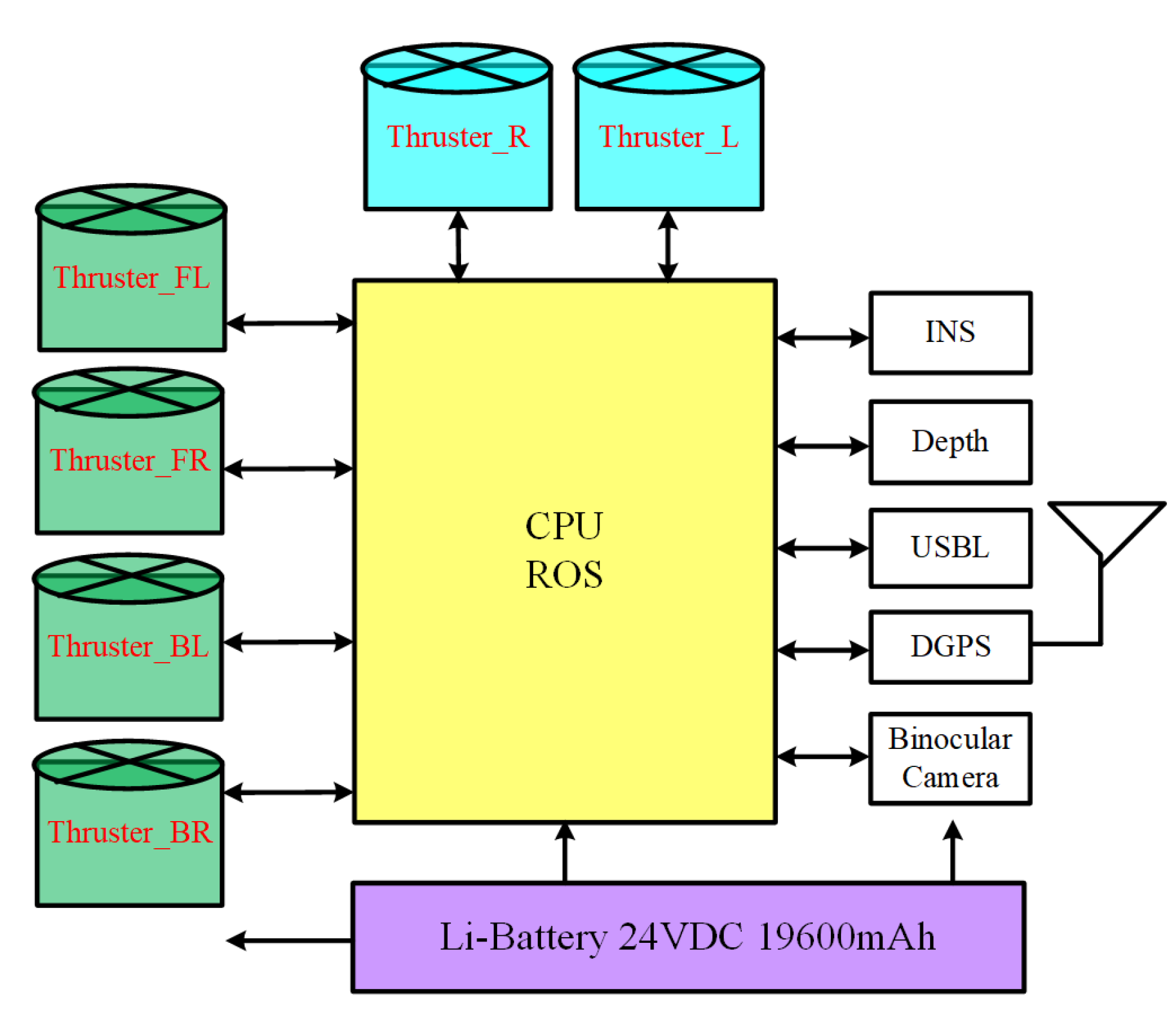
The detailed hardware structure of our self-made UQV is illustrated in
Figure 2. The hardware system is mainly composed of three parts: a core processor module, a perception module and a power supply module. The core processor module using Jetson-Nano board as the core processor is responsible for driving the six propellers in a completely autonomous motion operation. The perception system takes charge of underwater data acquisition and analysis with binocular cameras, an inertial navigation system (INS), a depth sensor, an ultra-short baseline positioning system (USBL), differential GPS (DGPS), etc. Therefore, the proposed UQV has the ability to obtain its real-time position. The whole UQV is powered by a 24V DC lithium battery. Six propellers are supplied by isolated power sources; among them, two horizontal propellers are mainly used to provide forward and turning force, and four vertical propellers are controlled to maintain specific posture for the UQV.
To design an obstacle avoidance path, the kinematic and dynamic model of the UQV with unknown dynamics and disturbances will be discussed.
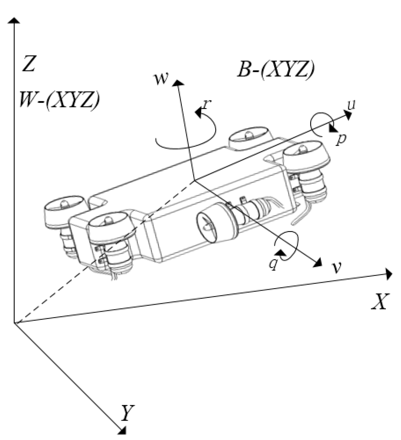
Figure 3 illustrates the dynamic model of the UQV in the earth coordinate system (
) and the body coordinate system (
), respectively. Four rotors provide lift in the body coordinate system, and its direction is vertical upward and parallel to the
. To counteract the reverse torque and gyro effect, four rotors are divided into two groups: the left-up and right-down rotors belong to one group, and the left-down and right-up rotors belong to another group. To ensure that the yaw angle does not change when hovering, we make two groups of rotors have opposite rotation directions, i.e., the rotation directions in the same group are the same and those in different group are opposite. Obviously, this kind of mechanical structure is the same as in a traditional unmanned aerial vehicle [
26].
For the convenience of formula description, the main notations used in this paper are defined in
Table 1.
With the symbols defined in
Table 1, there is
, and
, where two rotation matrices
and
from the body coordinate system to the earth coordinate system can be expressed as:
Let
denote the Velocity vector, and
denote the State vector, so the completed kinematics model of the proposed UQV is expressed as,
where
.
The essence of modeling the underwater quadrocopter vehicle is to apply Newton’s second law and Euler’s formula to analyze the stress force. Therefore, the completed dynamic model of the proposed UQV is expressed as [
25],
where
M is the inertia coefficient matrix,
is static resilience,
and
denote the Coriolis force–centripetal force matrix and the Damping coefficient matrix, respectively.
For simplicity, the well-designed UQV’s compound movement can be mainly divided into two separated motion modes: translational motion and rotational motion. The following subsections will analyze the two motion modes in detail.
2.1. Translational Motion
For the translational motion of the underwater quadrocopter vehicle, the force equation of the UQV in the earth coordinate system can be obtained according to Newton’s Second Law, that is,
where
m denotes the quality of the underwater quadrocopter vehicle and
,
and
denote different acceleration values of the
in the earth coordinate system, respectively.
The resultant force of the proposed UQV is mainly composed of four groups: its own gravity, the buoyancy from water, the force generated by the two propellers and the lift provided by the four rotors. For the forces
and
from the two horizontally placed propellers, their directions are along the
. The lifting forces
are generated by the four rotors, and their directions are along the
of the body coordinate system (
). The directions of gravity and buoyancy are along the
in the earth coordinate system (
); hence, it is necessary to convert the force in the body coordinate system to the earth coordinate system. Through the predefined rotation matrix
, we can obtain,
where
and
. Therefore, Equation (
4) can be expanded to,
2.2. Rotational Motion
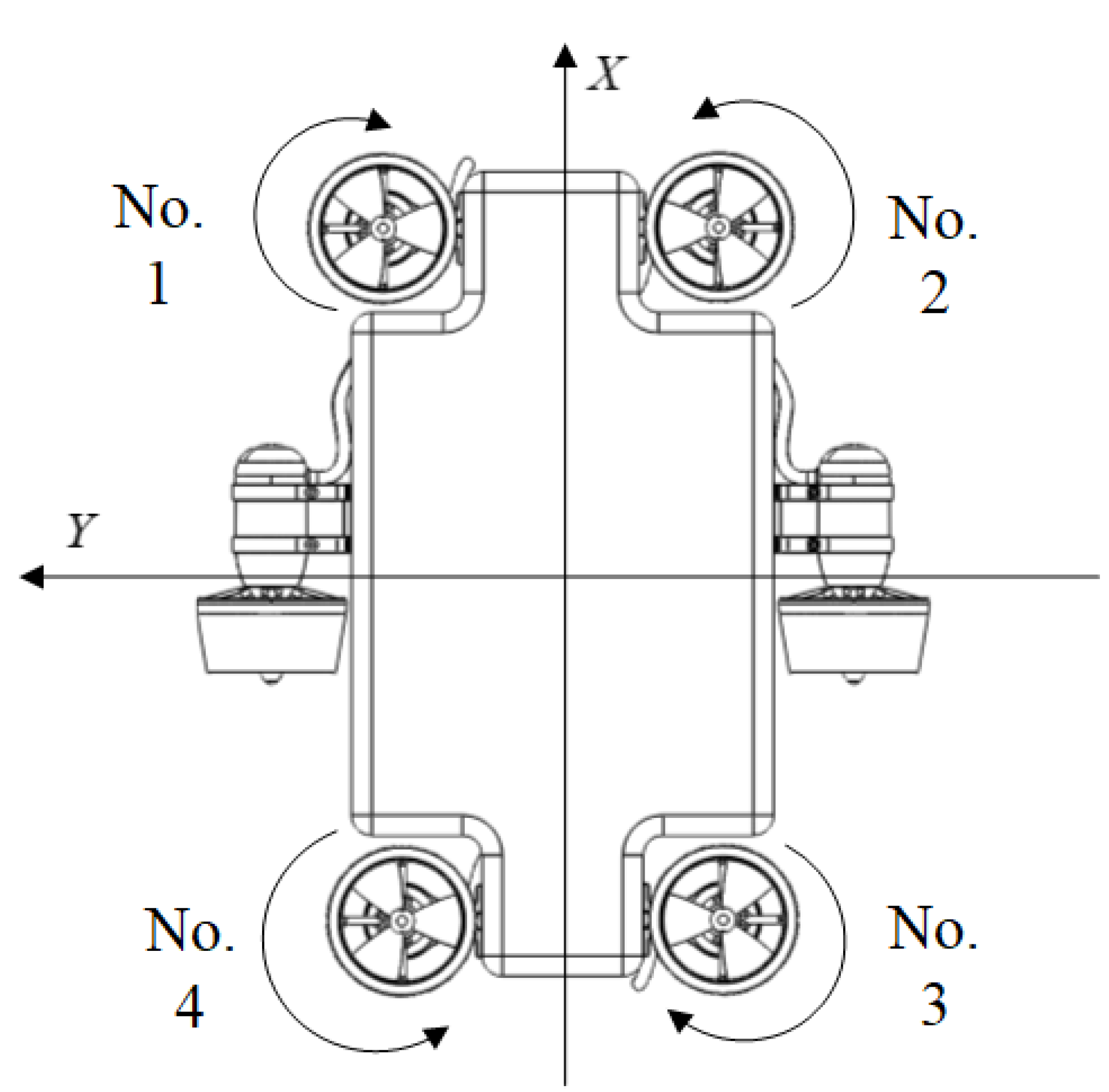
The rotational motion of the UQV is mainly caused by the imbalance of torque. In the rotational motion, the imbalance of torque comes from different forces generated by the four rotors. As
Figure 4 shows, the rotating direction of each rotor is specified with the given reference direction of
and
in the body coordinate system. The reference direction of
is determined outward from the
plane using the right-hand rule. Consequently, the rotational motion can be analyzed as follows:
The torque calculation equation is defined as:
where
L denotes the distance vector from the axis of rotation to the force point and
denotes the force vector applied to the UQV. Through the torque formula, the following equations can be established in the body coordinate system,
where
denotes the different arm of force related to the different propulsive force.
The internal stress in the
direction is mainly generated by the imbalance from the moment of force when the two group rotors rotate. The rotor rotating clockwise will produce a reversal torque, making the rigid body rotate counterclockwise and vice versa. Therefore, in
Figure 4, the reversal torque generated by the No.1 and No.3 rotors is along the positive
direction, and the reversal torque generated by the No.2 and No.4 rotors is along the negative
direction.
Through the rigid body rotation theorem and Euler equation, there is:
where
is the total external moment of force in a certain fixed axis,
M is the inertia matrix, and
is the angular acceleration,
,
.
The rotation equation under six degrees of freedom can be obtained as,
where
is the coordinate of the gravity centre. Since the structure of the UQV is symmetrical, the inertial matrix can be rewritten as a diagonal matrix, i.e.,
. Hence, the above equation can be reduced to the following equation,
Let
denote linear damping coefficients of Surge, Sway, and Yaw, respectively;
denote added mass coefficients of Surge, Sway, Yaw, respectively; and
denote secondary damping coefficients of Surge, Sway, Yaw, respectively. Hence, the inertia coefficient matrix
M, the Coriolis force–centripetal coefficient matrix
and the hydrodynamic damping matrix
can be derived as follows,
where
is the moment of inertia in the
.
3. Binocular-Vision-Based Underwater Obstacle Positioning
Binocular stereo vision uses two parallel cameras to capture an object of interest and then calculates two similar images’ deviations, finally obtaining a clear sense of depth from the correspondence between features. Nowadays, binocular stereo vision has been widely used with the advantages of simple equipment, low cost and less human intervention [
27,
28]. Herein, the binocular-vision-based underwater obstacle positioning principle is described in
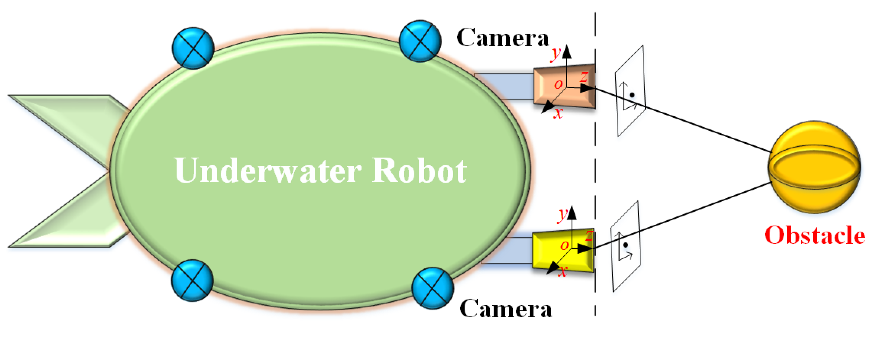
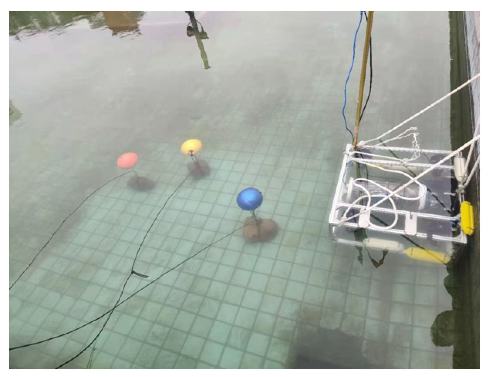
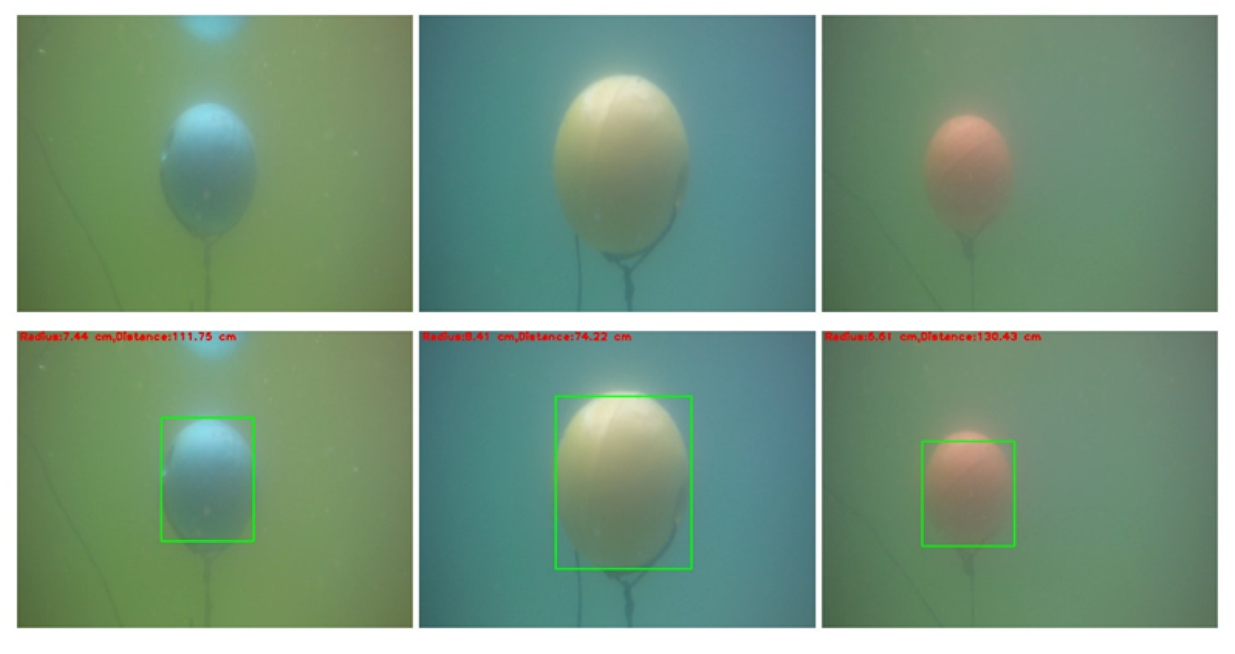
Figure 5. Two parallel underwater cameras mounted on the head of the UQV are used to capture imaging information ahead. Using the underwater binocular-vision-based obstacle positioning method, an underwater spherical obstacle’s size and the distance from the UQV will be calculated in a simple mode.
Traditionally, the binocular vision processing procedure can be divided into three main components. First, due to the congenital difference between the left camera and the right camera, the captured images will be distorted. Therefore, the first important step is camera calibration using derived distortion parameters. Second, a stereo matching algorithm is applied to calculate the parallax between the left image and the right image. To improve the accuracy of the disparity calculation in the binocular image matching process, the two cameras’ external parameters are applied to correct the target’s position deviation on the left and the right imaging plane. Third, the two cameras’ internal parameters are used to correct pixel deviation; consequently, the actual target’s position is projected according to the parallax of the target on the left and the right imaging pictures. Similarly, the proposed binocular-vision-based underwater obstacle positioning method is divided into three steps.
3.1. Step 1: Binocular Camera Calibration
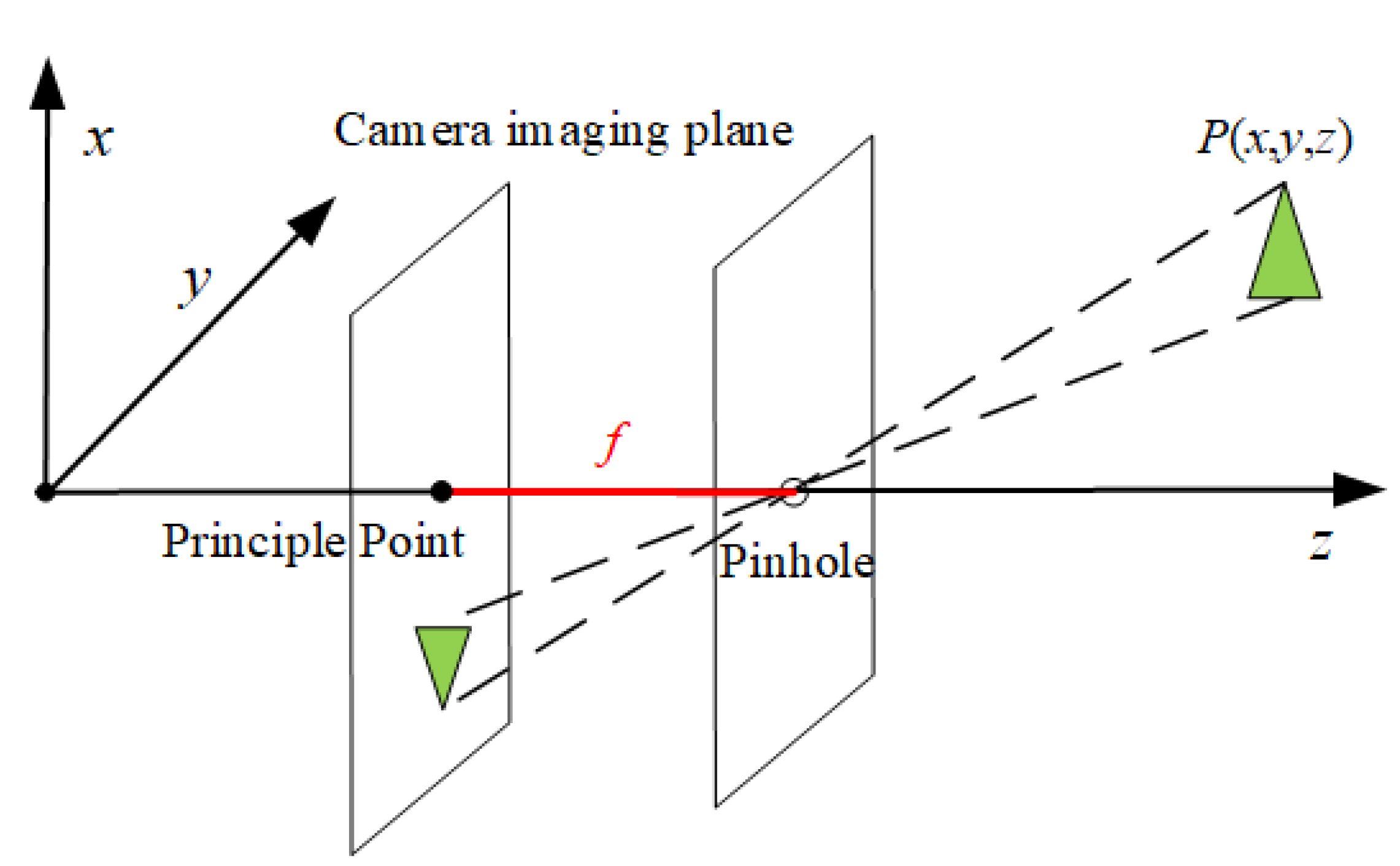
According to the pinhole imaging model, the target
will be projected onto the imaging plane. For an ideal pinhole camera as shown in
Figure 6, the straight line distance from the pinhole to the projection plane is defined as the focal length
f. Ideally, the principal point and the projection center should be on the same optical axis. However, due to the limitations of the cameras’ manufacturing process, the principal point and the projection center are not usually on the same optical axis. Therefore, it is necessary to correct the cameras’ offset using a certain calibration method. The famous Zhang Zhengyou calibration method [
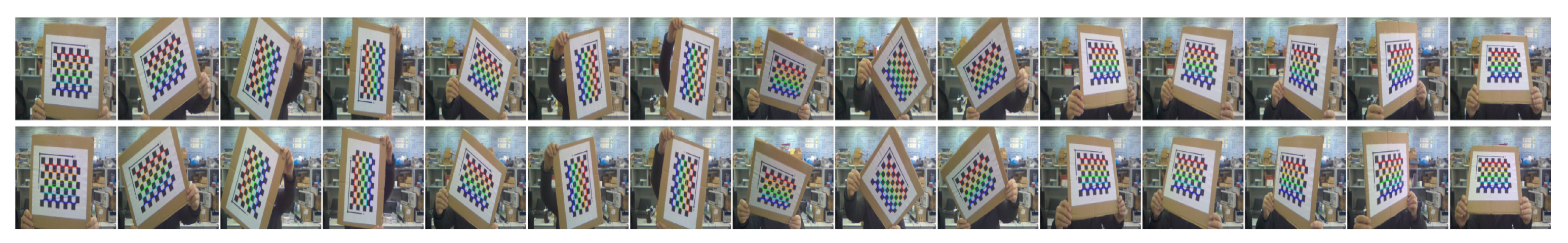
29] is applied in this section, and chessboard calibration images with different angles as shown in
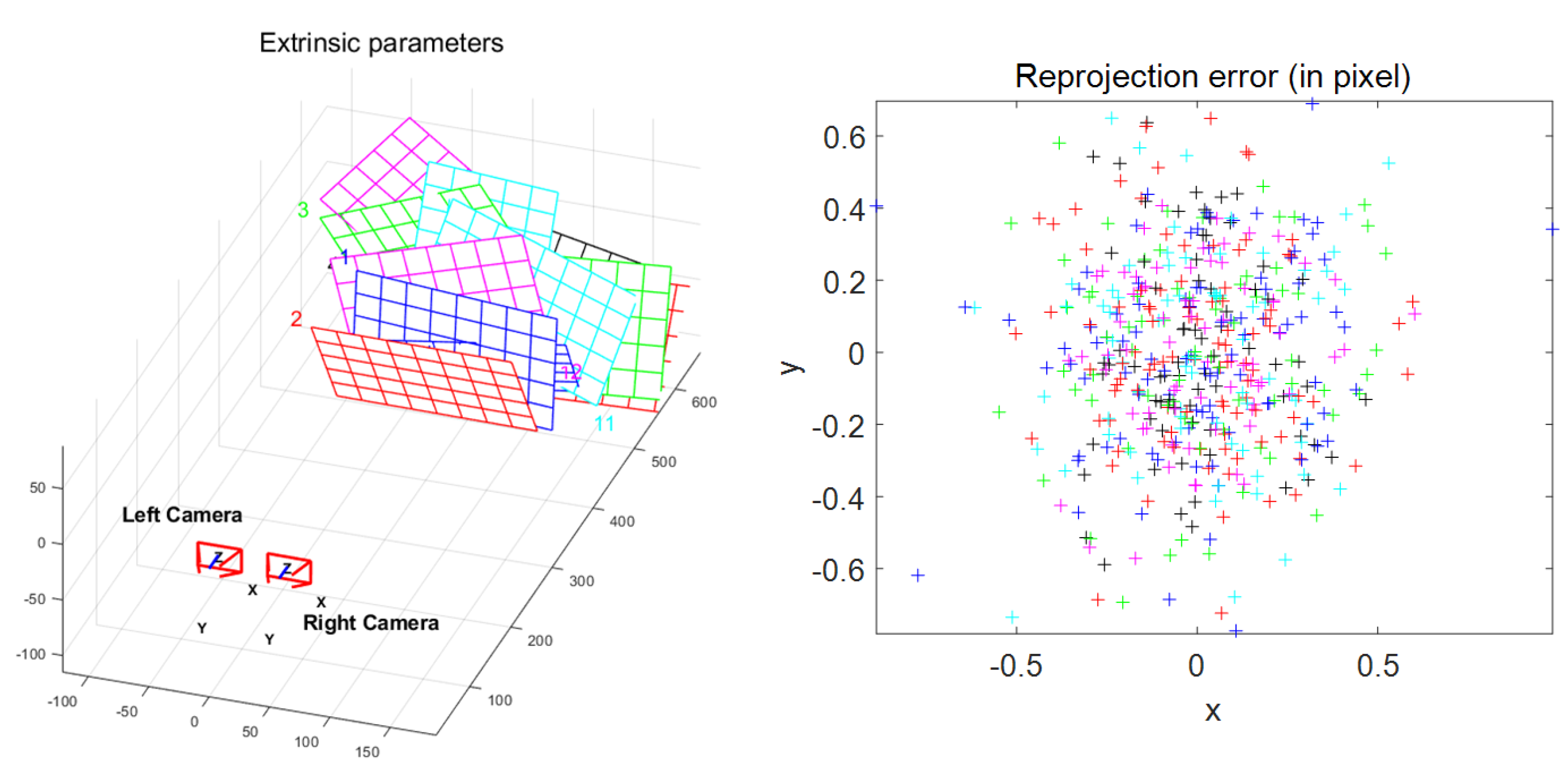
Figure 7 are used. In this paper, 14 chessboard calibration maps with different angles are collected for camera calibration. The chessboard collected by the left and right cameras is modeled and analyzed by MATLAB to obtain the correction parameters. The spatial position relationship between the binocular camera and the calibrated chessboard and the distributions of projection error of each image are described in
Figure 8. Different color punctuation points distributed in the error diagram represent different errors of the chessboard corners.
Figure 8 demonstrates that projection errors mostly approach zero, indicating that the image calibration effect is very good. The average error pixel points of each image indicated with the red line is 0.032489 pixels; therefore, it is verified that these camera calibration results are feasible.
Finally, the internal and external parameters of the used underwater cameras can be obtained following a traditional treatment process [
27]. For the sake of space, these traditional processing methods are outside the scope of this article.
3.2. Step 2: Underwater Binocular Matching
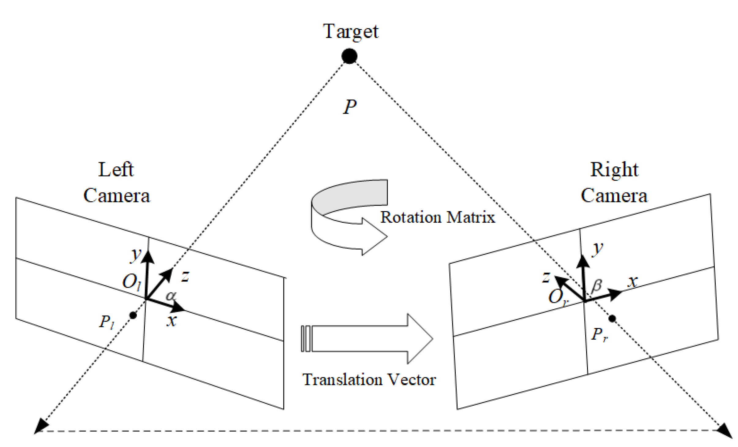
As we know, the imaging planes of the left camera and the right camera usually cannot be the same in the binocular vision technology, so it is difficult to locate a common part in the stereo matching algorithm. Therefore, it is necessary to apply external correction parameters to align the polar line. In
Figure 9, taking the center of the imaging plane of the left camera as the origin of coordinate system
, the mark of the observed target
P is
. Similarly, taking the center of the imaging plane with the right camera as the origin of coordinate system
, the mark of the observed target
P is
. Following the relationship between pixel coordinates and physical coordinates, there are,
where
and
are the rotation matrix and the translation vector in
Figure 9.
As a conventional method, the relationship between pixel coordinates and physical coordinates in the left and right imaging planes is described in Ref. [
30].
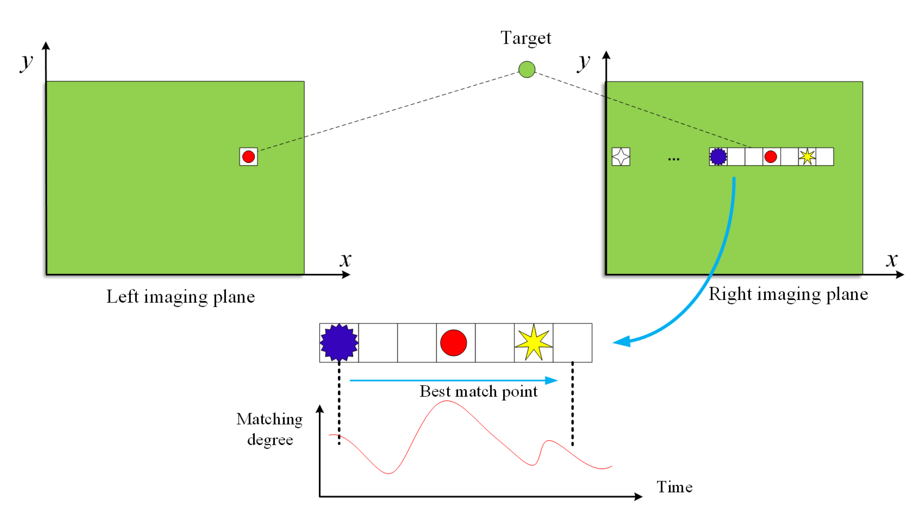
So far, these matching points can be found in the visualization area where two camera views overlap. Once the triangulation parallax between the corresponding points of two views is known, the target’s depth can be obtained using the triangle similarity principle. The well known block matching stereo-matching algorithm with a small ’Sum of Absolute Differences (SAD)’ window [
31] is applied to find the matching points between the two images as
Figure 10 shows. The block matching stereo-matching algorithm is implemented in three steps. First, the binocular image is pre-processed to normalize the image’s brightness, to reduce brightness distortion, eliminate noise and enhance texture. Second, we use the previous SAD window to search for the optimal matching of each feature in the left image and the right image. After stereo-matching searching, the best matching point will be determined, i.e., the smallest SAD function value of the matching window is chosen. After block stereo matching, any conventional roundness extraction methods can be used to identify the target. For the sake of paper space, we will ignore explaining these traditional processing methods. After these steps, if the obstacle is spherical, its radius
R can be obtained with an image pixel plane.
3.3. Step 3: Obstacle Depth Computing
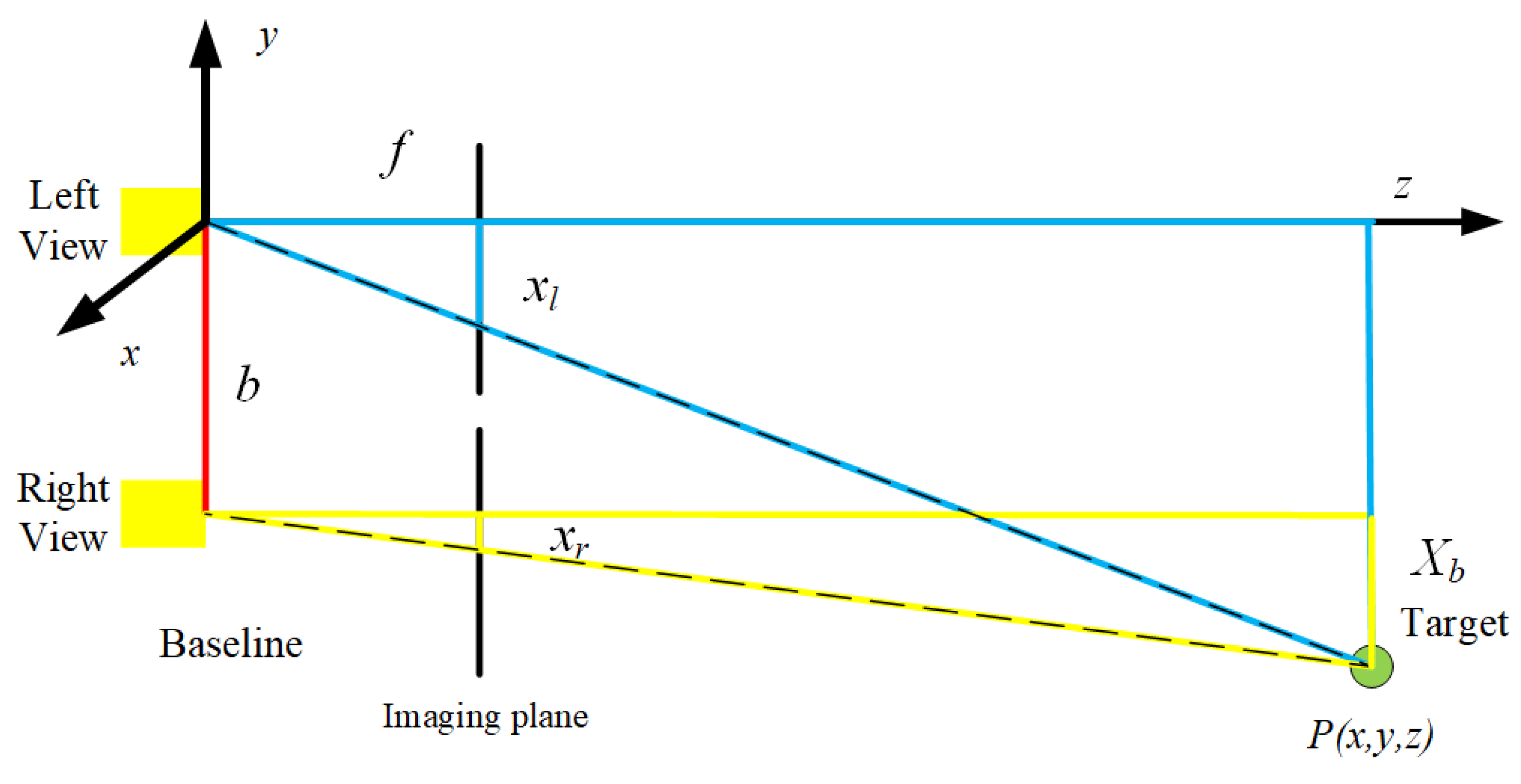
In this paper, two deployed cameras are exactly the same with focal length
f, and the positions are completely parallel along the UQV’s body. It is assumed that the baseline length of the left camera and the right camera is
b, the coordinate of the target point is
, the target point’s imaging coordinates of the left camera and the right camera are
and
, respectively. According to the triangle similarity principle between the blue triangle and the yellow triangle in
Figure 11, there is such Equation,
where
d is the distance between the UQV and the spherical obstacle, and it is the key parameter for obstacle avoidance path planning. Hence, we can obtain the actual coordinates of the target point,
Finally, the distance d between the underwater obstacle and the UQV and the radius R of the spherical obstacle can be obtained with the binocular-vision-based underwater obstacle positioning method. It is worth noting that in our application scenario.
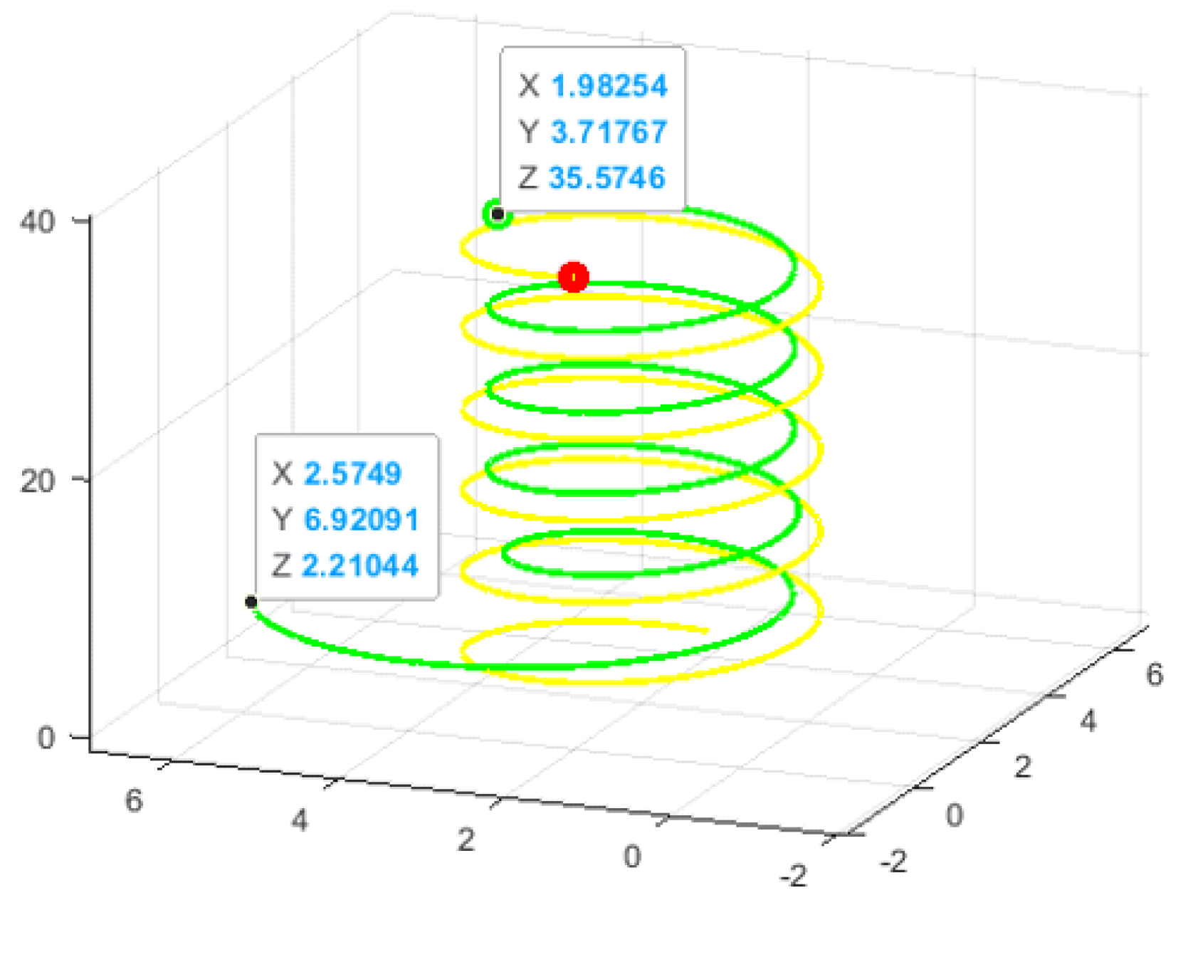
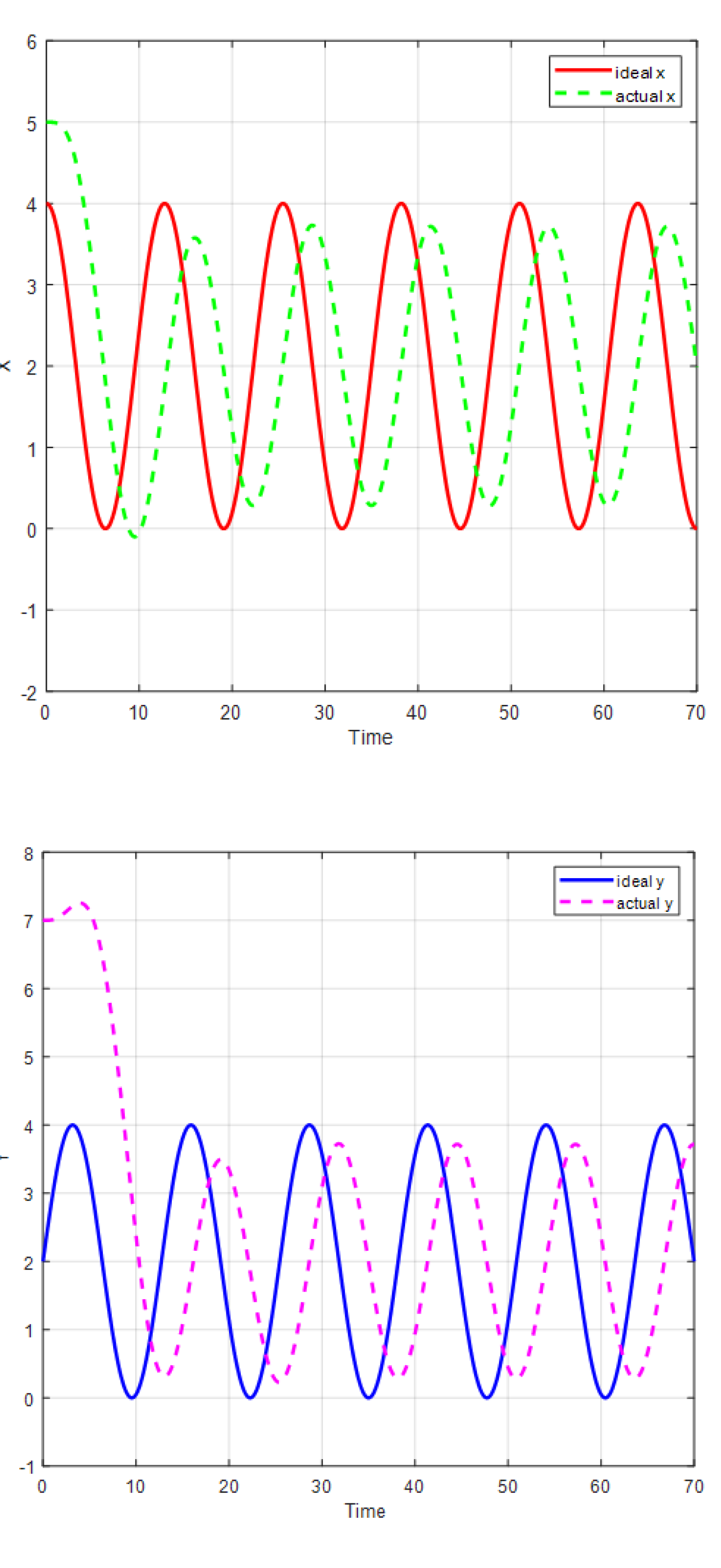
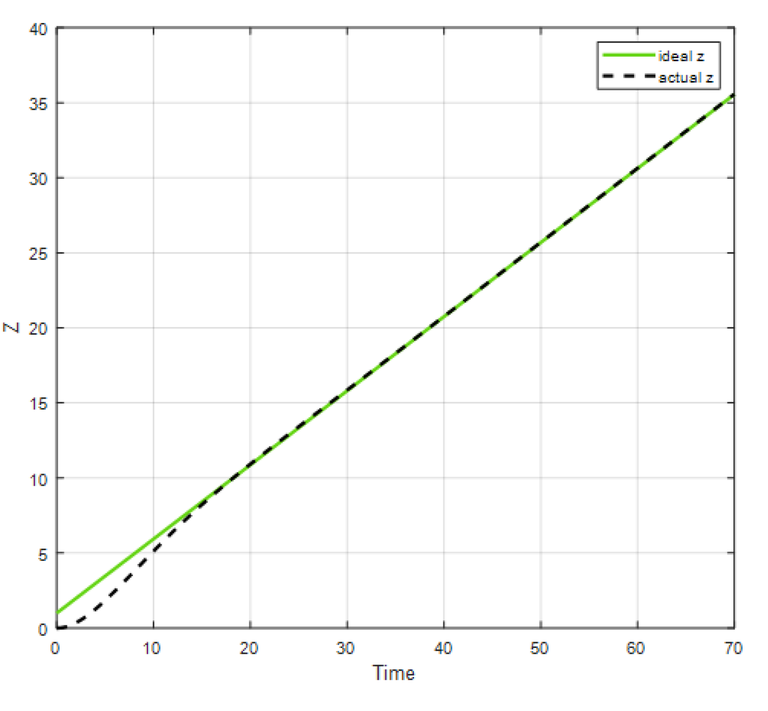
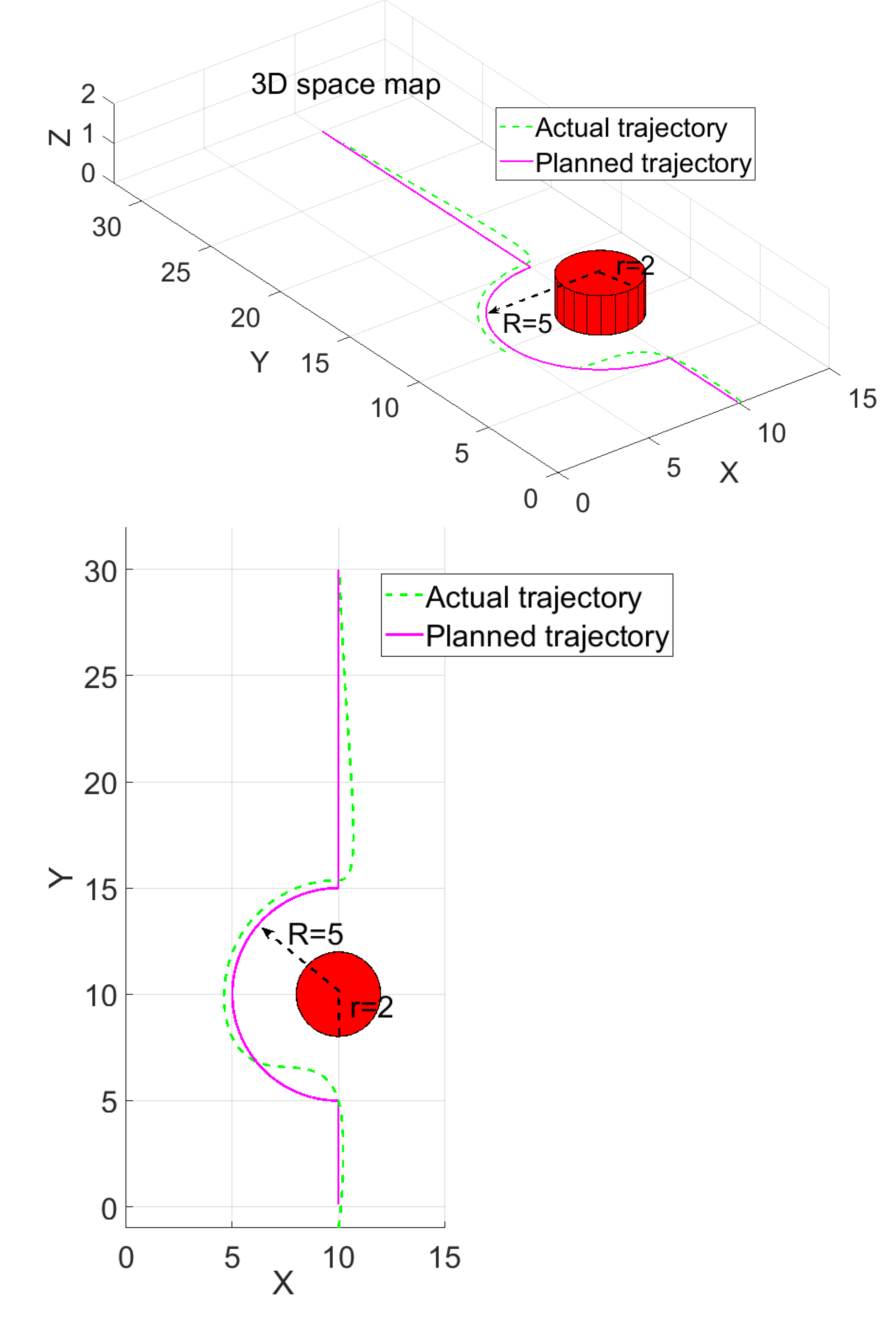
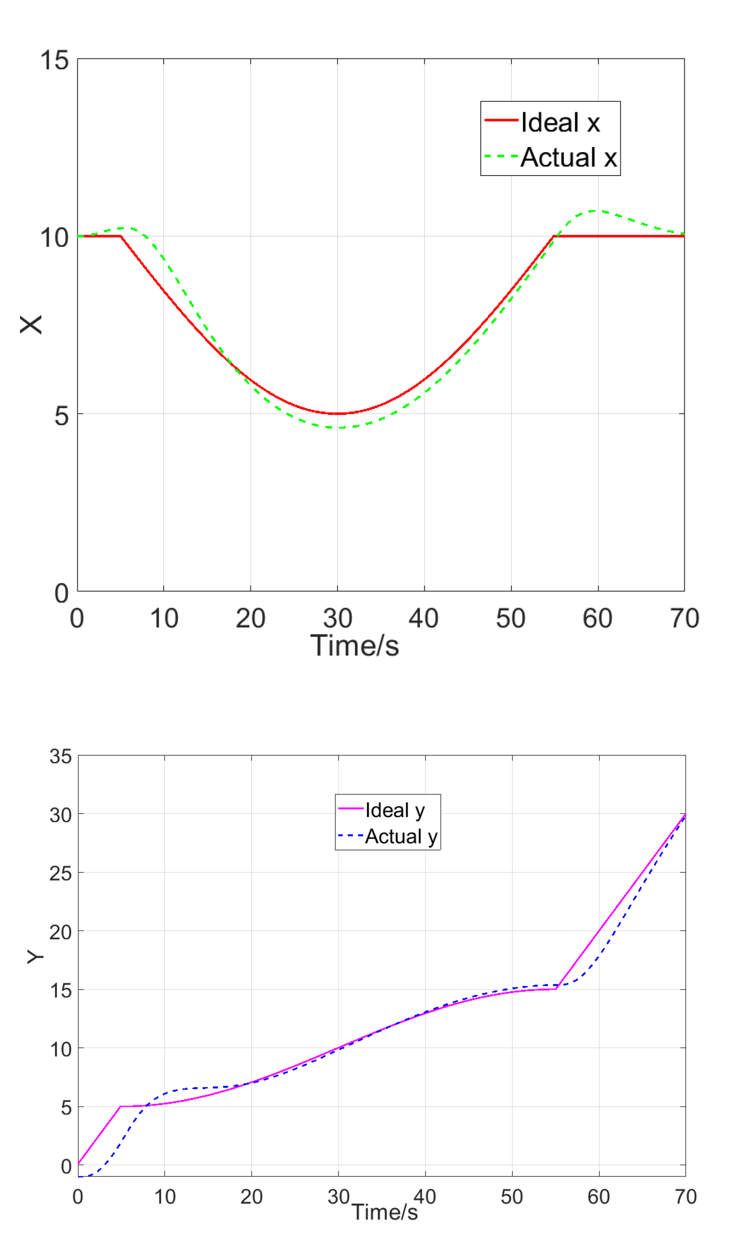
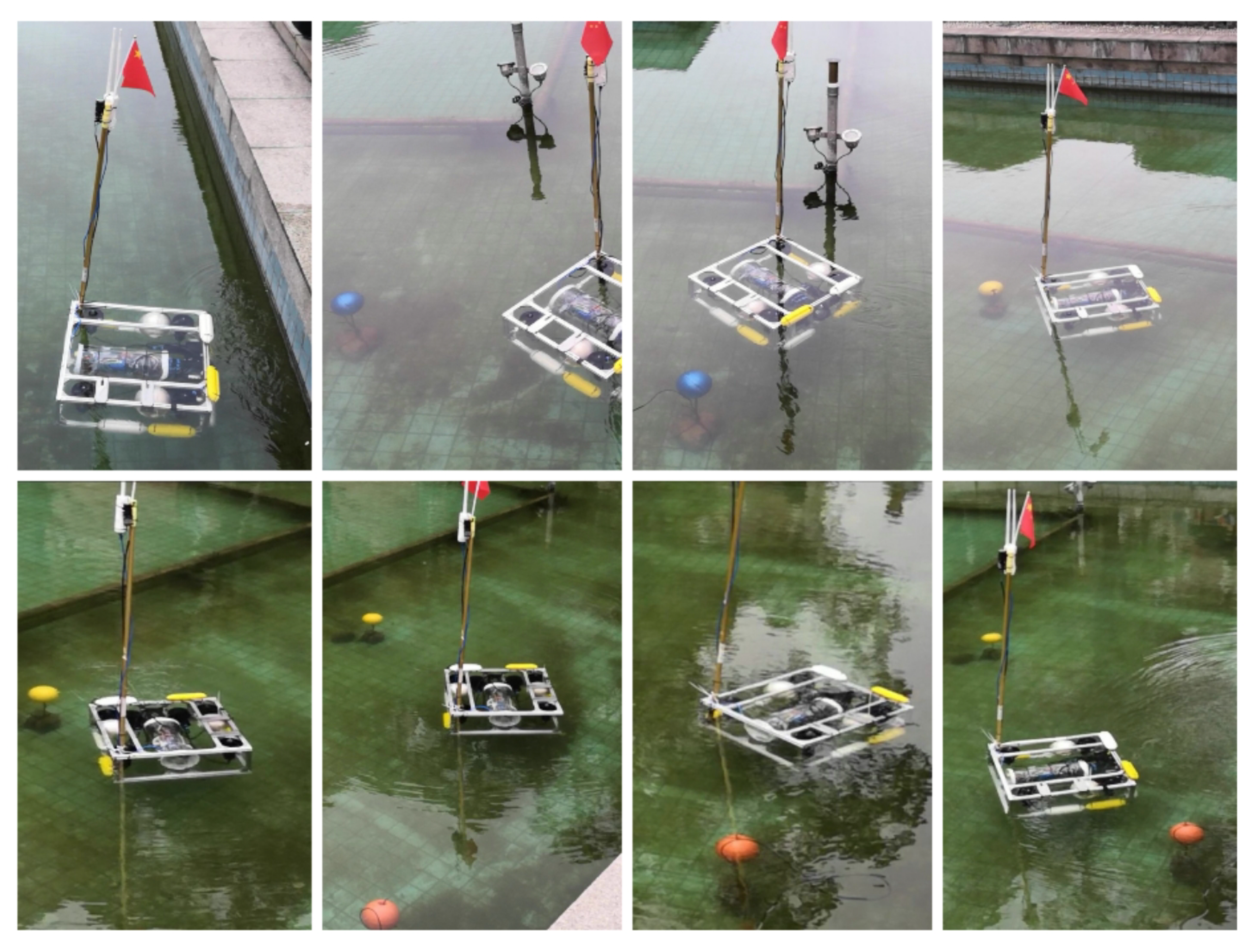
4. Obstacle-Avoidance-Based Continuous Path Design
So far, the relative distance d away from the UQV and the radius of the spherical obstacle can be determined with the previously introduced binocular visual positioning method. In this section, we will discuss how to design an obstacle-free trajectory.
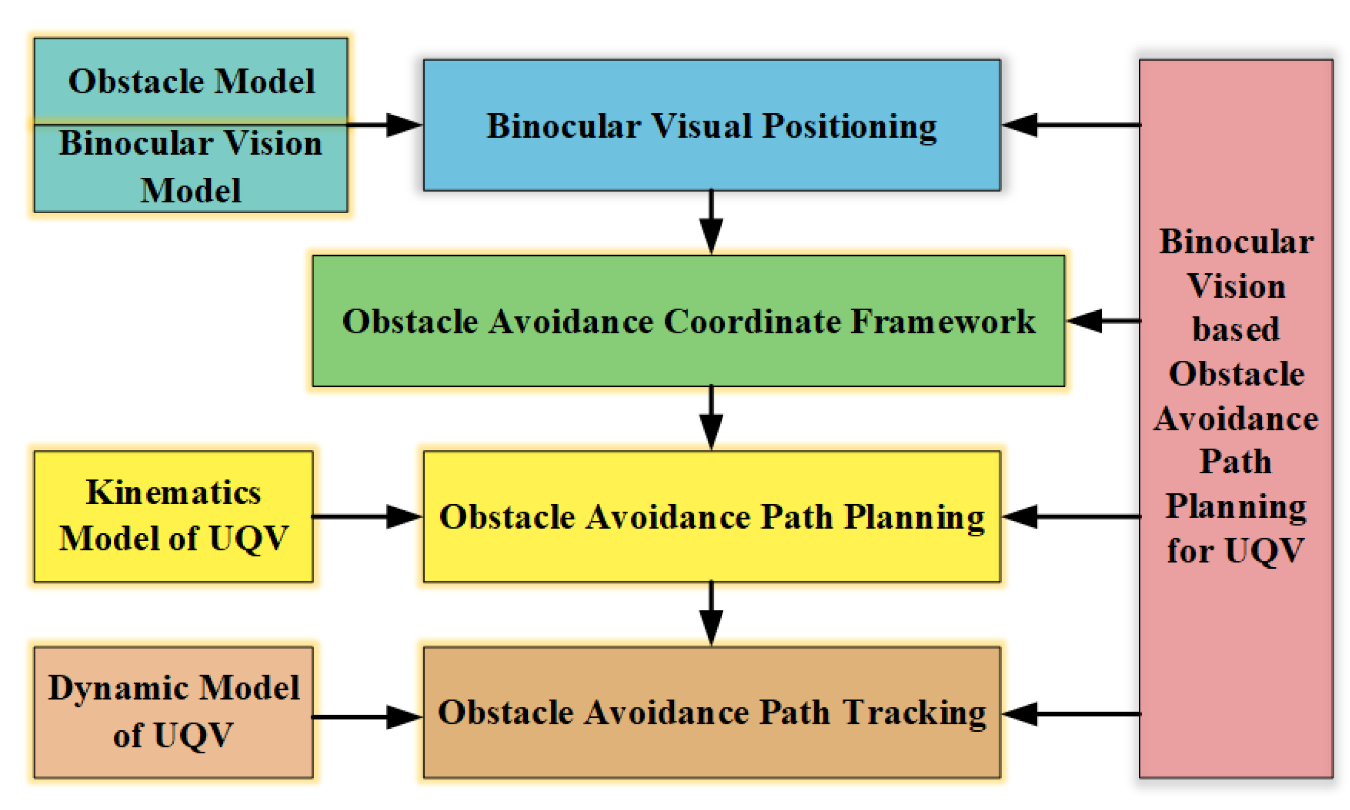
The detailed framework of obstacle avoidance path planning is described in
Figure 12 It can be divided into four main parts: binocular visual positioning, obstacle avoidance coordinate framework, obstacle avoidance path planning and obstacle avoidance path tracking. The binocular visual-positioning module is used to obtain the obstacle’s location, which is demonstrated in the previous sections.
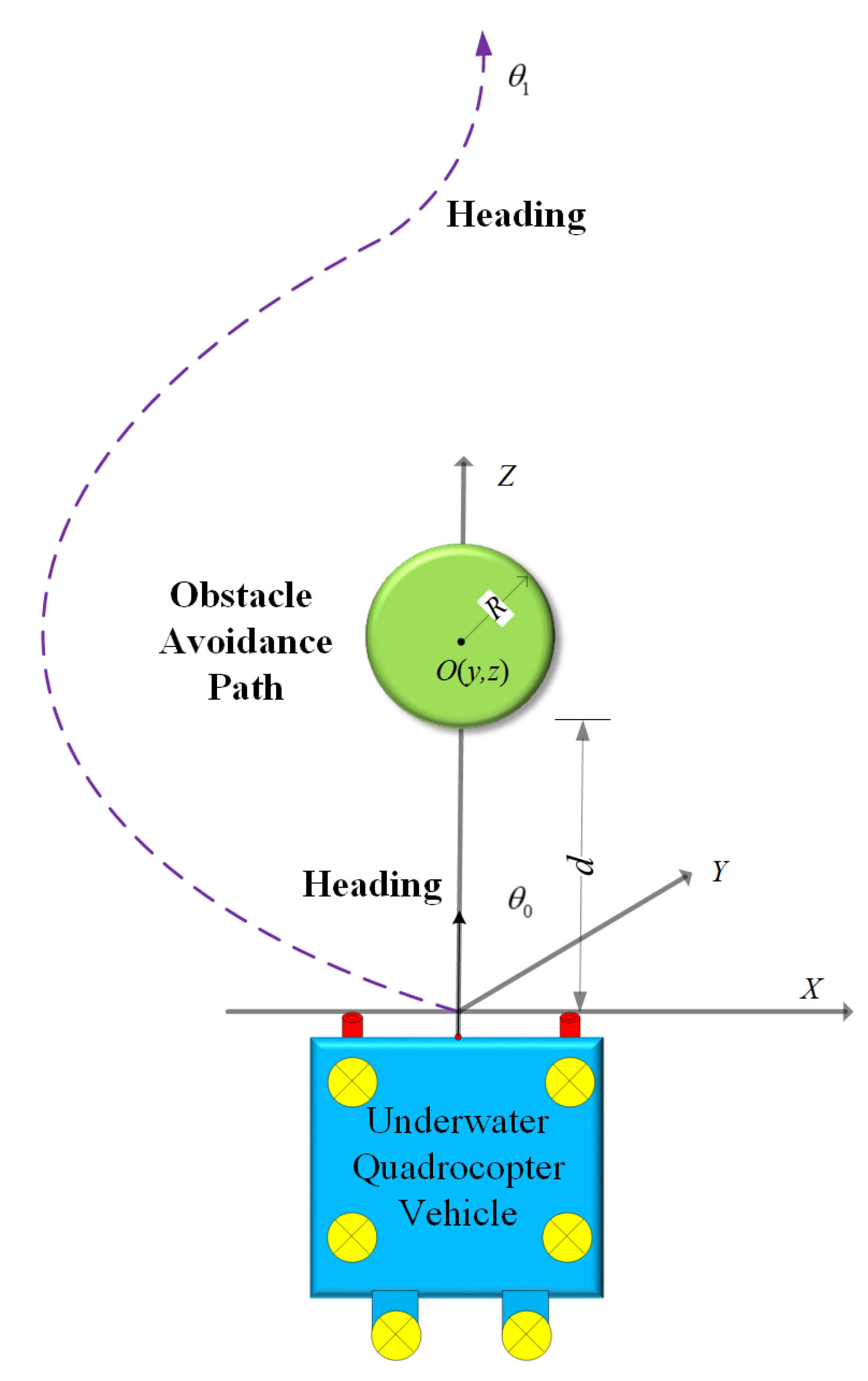
The obstacle avoidance framework determines how to design the obstacle avoidance path with the knowledge of obstacle information. The applied coordinate system constructed by the self-designed UQV and the spherical obstacle is constructed in
Figure 13. Although the proposed obstacle avoidance framework is a three-dimensional coordinate system, it is assumed that the UQV and the underwater obstacle are at the same depth, i.e, with the same
Y coordinate. Hence, we only consider an obstacle-free trajectory in a two-dimensional plane.
Specifically, it is assumed that the center of spherical obstacle
O is
, and its radius is
R. The original heading of the UQV is
, and the front center of the UQV is
. The investigated obstacle avoidance path planning is to choose one smooth trajectory
, which satisfies, each point
in the planned trajectory such that
is satisfied,
subject to the starting heading equal to the ending heading approximately:
.
The obstacle avoidance path planning is derived from the kinematics model of the UQV. To realize the obstacle avoidance mechanism in the embedded system, a semicircle path with radius
is used to design the obstacle avoidance path in this paper. In
Figure 13, the obstacle avoidance path is decided as a semicircle with radius
, i.e., the starting point and the ending point are
and
, respectively. The variable
d is the relative distance between the UQV and the spherical obstacle’s center, which has been determined by the previous binocular visual positioning method. In actual execution, once the front underwater obstacle is identified, the above obstacle avoidance path calculation process will start. Furthermore, it is worth mentioning that the obstacle avoidance trajectory is designed only in the
plane, and the influence in the
is ignored.
The last obstacle avoidance path tracking module is controlled by the dynamic model of the UQV. Due to its full degree of freedom of movement, the introduced UQV can perform various actions such as turning any angle in a fixed place following the planned trajectory. Therefore, any successive curves can be used by the motion controller as long as the heading angle constraint is satisfied in the previous obstacle avoidance model.


