Article

Study on Position and Shape Effect of the Wings on Motion of Underwater Gliders

1
Department of Mechanical Engineering, Korea Maritime and Ocean University, Busan 49112, Korea
2
Interdisciplinary Major of Ocean Renewable Energy Engineering, Korea Maritime and Ocean University, Busan 49112, Korea
3
Department of Technology, Dong Nai Technology University, Bien Hoa 810000, Vietnam
4
Korea Institute of Industrial Technology, Busan 46041, Korea
5
Department of Ocean Advanced Materials Convergence Engineering, Korea Maritime and Ocean University, Busan 49112, Korea
6
Faculty of Electrical and Electronics Engineering, Ho Chi Minh City University of Technology (HCMUT), Ho Chi Minh 700000, Vietnam
*
Author to whom correspondence should be addressed.
J. Mar. Sci. Eng. 2022, 10(7), 891; https://doi.org/10.3390/jmse10070891
Submission received: 24 May 2022 / Revised: 22 June 2022 / Accepted: 24 June 2022 / Published: 28 June 2022
(This article belongs to the Special Issue Advances in Marine Vehicles, Automation and Robotics)

Abstract

:
A typical structure of an underwater glider (UG) includes a pair of fixed wings, and the hydrodynamic force driving the glider forward as descending or ascending in the water is generated primarily by the fixed wings. In this paper, a simplified glider motion model was established to analyze the dynamics in an easier way, and whose simulation results do not differ from the original one. Also, in the paper, the effects of the wing position and wing shape on the UG to the motion were studied. Since no direct analytic approach cannot be performed, the case study of the effects of six different wing positions and three wing shapes on gliding performances which are gliding speed, gliding angle and gliding path were performed through computer simulation. The simulation results revealed that when the fixed wing is located far from the buoyancy center to the tail end, more traveling range is achieved with less energy. Also, effect of the shape difference of the wings were analyzed. Shape changes did not show much difference on the travelling performance of the UG. In addition to these, the transient mode of the UG was studied. To control this, the PID controller for the position of the mass shifter and piston were applied. By application of the PID controller to the linearized dynamics equations, it was shown that the transient behavior of the UG was quickly and steadily controlled.

1. Introduction

The underwater glider (UG), which is a type of underwater autonomous cruise platform, is equipped with a buoyancy adjustment system that changes its buoyancy in water to drive its body underwater [1] and a movable mass mechanism that adjusts the position of the internal mass block to control its attitude while navigating underwater [2]. The change in net buoyancy is adjusted to make the glider move up and down in the vertical plane underwater in a saw-tooth pattern [3]. Compared with the traditional thruster or propeller-driven underwater vehicles, the UG has lower energy consumption and noise, which enables it to have longer endurance and wider underwater working envelope [4]. These advantages make it competent for military applications such as underwater hydrographic environment investigation and underwater mapping.
A typical torpedo-like UG consists of a fuselage, a rudder, and a pair of fixed wings. The fuselage consists of a mass-shifting system for altering the gliding attitude, a buoyancy engine system (bladder or pump type) for varying the net buoyancy, and a glider control unit and other accessories; the rudder is primarily used for yaw control of the glider to turn the motion direction and expand the detection scope. The fixed wing, which is an essential part, transforms sinking/floating motion into horizontal motion when the glider moves downward or upward owing to variations in net buoyancy [5].
UGs are subject to hydrodynamic forces, such as hydrodynamic lift, hydrodynamic drag, and hydrodynamic moment, from the water when moving underwater. When designing the airfoil for a specific glider, the maximum lift-to-drag ratio [6] and the minimum hydrodynamic moment [7] must be determined. In a previous study, the effects of two different airfoil constructions on the gliding performance of gliders were compared based on numerical and experimental methods [8]. The optimal design parameters of the National Advisory Committee for Aeronautics (NACA) airfoil were obtained by performing hydrodynamic analysis of the glider airfoil using computational fluid dynamics (CFD) [9]. Furthermore, the influence of NACA airfoil shape on the gliding economy and stability of UG was analyzed using hydrodynamic method [10]. Studies have also applied hydrodynamic calculation techniques based on CFD to estimate the hydrodynamic parameters of the underwater vehicle [11,12,13]. The effect of wing layout on the motion efficiency and stability of the hybrid underwater glider were investigated by experimental design and computational fluid dynamics methods [14]. The effect of wing configuration on flight efficiency in gliding motion and maneuverability in spiral and horizontal turning motions was investigated [15].
The main objective of this paper is to analyze and compare the effect of fixed wing position and wing shape on glider motion through simulation. In addition to these, the transient mode of the UG changes by the effect of fixed wing position and wing shape are simulated. The role of the PID controller for the position of the mass shifter and piston to control the transient mode is presented.

2. Dynamics of the Glider

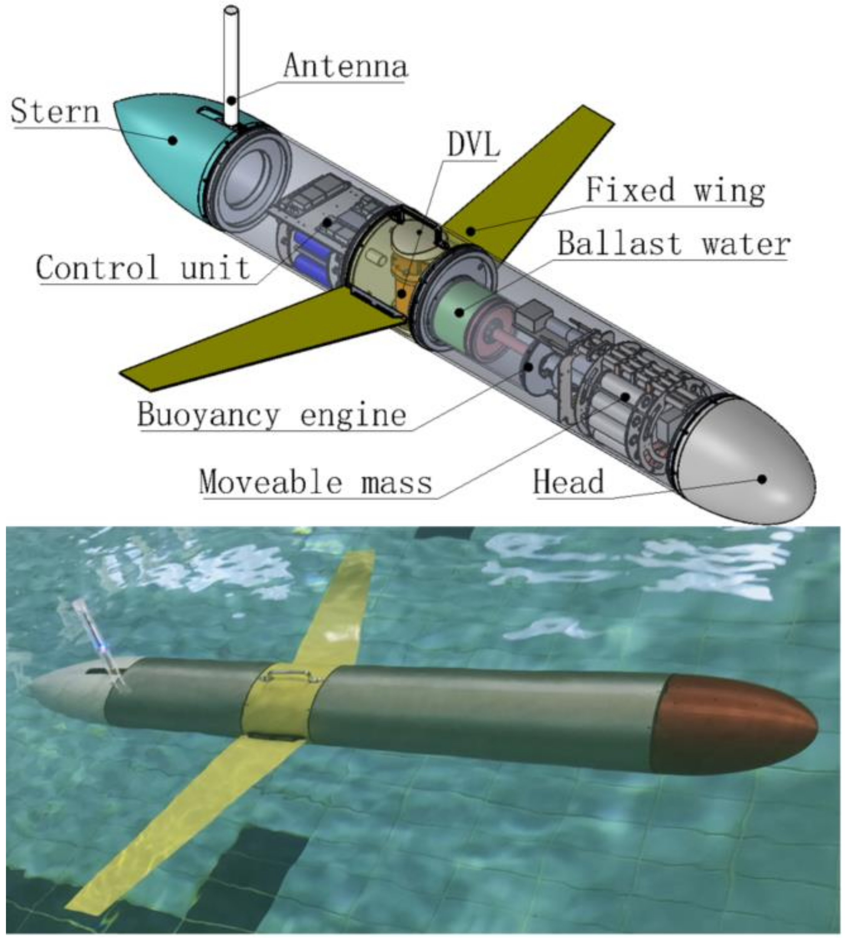
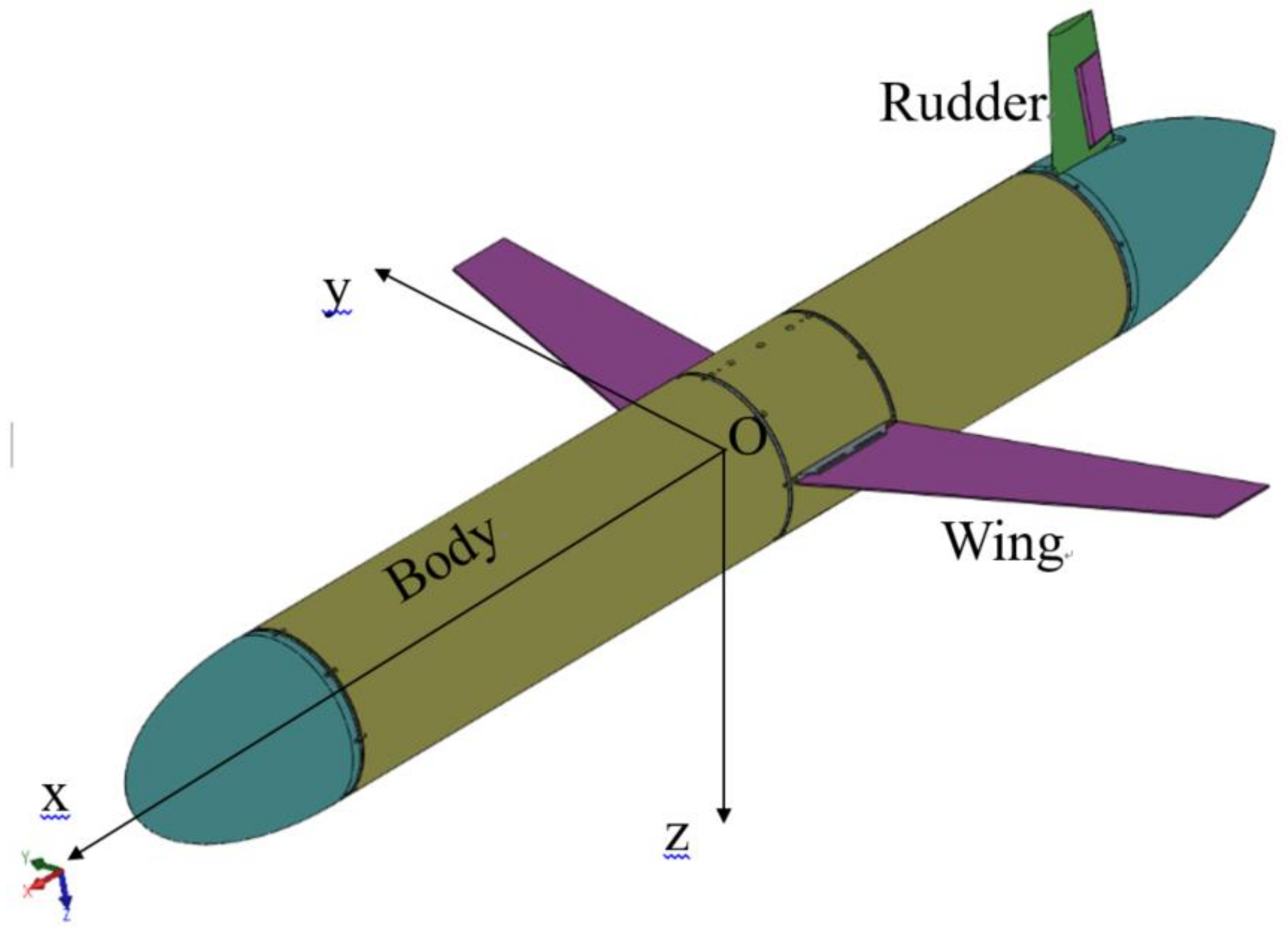
2.1. Structure of the UG

A torpedo-like glider is displayed in Figure 1 [16]. The glider is categorized into the head, middle, and tail parts. The middle part consists of several parts, including the movable mass block, buoyancy engine, fixed wing, and control unit. The glider pitch attitude and net buoyancy can be changed by adjusting the position of the movable mass block and moving the piston in the buoyancy engine, respectively. Adjusting the glider buoyancy can enable the glider to sink underwater or float.
In mathematics and physics, the moment is the product of the vertical distance between the acting force and the line of action of the force. Moment is mathematically expressed as follows:
τ = r × F
where r is the distance of the force F to the point of action (the center of buoyancy).
A UG is subjected to the following hydrodynamic forces when it (Figure 2) moves in the vertical plane: hydrodynamic drag of the rudder and hydrodynamic lift and drag of the wing and body. Generally, the structure of the glider is symmetric about the x-z plane and approximately symmetric about the x-y plane. Furthermore, its buoyancy center position is in the x-z plane and close to the x-y plane or in the x-y plane.
Based on Equation (1), the hydrodynamic moment ( M D L ) of an UG rotating about the y-axis with vertical motion in the x-z plane expressed as follows:
M D L = L W d w x + D W d w z + L B d b x + D B d b z + D R d r z
where L W and D W are the hydrodynamic lift and drag of the fixed wing, d w x and d w z are the vertical distances from the line of action of the lift and drag of the wing to the floating center, L B and D B are the hydrodynamic lift and drag of the body, d b x and d b z are the vertical distances from the line of action of the lift and drag of the body to the floating center, respectively, and D R and d r z are the rudder drag and vertical distance from the line of action of the drag to the floating center, respectively. Because the glider is approximately symmetric about the x-y plane, both d w z and d b z have small values close to 0. For a UG with the given structural parameters of the airframe and rudder, the distance of the action of the wing lift can be varied considerably in Equation (2), which affects the hydrodynamic moment.
The UG reaches a state of force equilibrium in steady-state gliding because of the interaction of hydrodynamic forces, gravity, and buoyancy forces during underwater diving and surfacing. As displayed in Figure 3, if the point of action of lift L is located behind the buoyancy center (-x-axis direction), then the moment of the lift and gravity (G) relative to the buoyancy center around the y-axis is in the same direction during the dive and surfacing phases. By contrast, if the point of action of lift L is located in the front of the buoyancy center (+x-axis direction), then the moment of lift and gravity relative to the buoyancy center around the y-axis is in the opposite direction. Figure 3 illustrates the forces of the glider in the steady-state diving and surfacing.

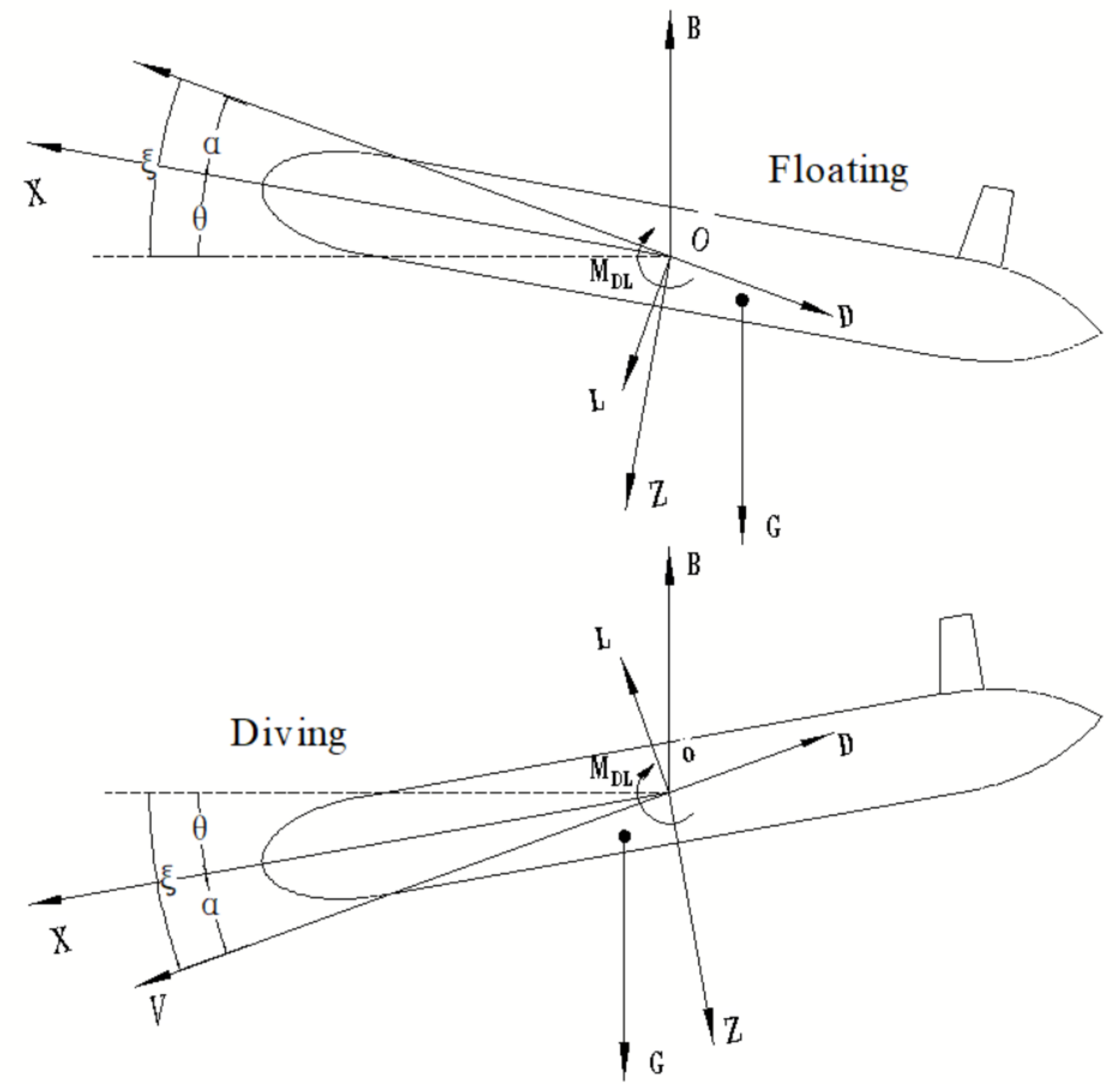
2.2. Glider Dynamics

The equations for glider motion in the vertical plane were expressed in [16], and the original dynamic equations were obtained using the Newton–Euler motion, and the dynamic equations are shown as follows:
x ˙ = v 1 cos θ + v 3 sin θ
z ˙ = v 1 sin θ + v 3 cos θ
θ ˙ = ω 2
v ˙ 1 = 1 m 1 m 3 v 3 ω 2 p m ¯ 3 ω 2 P p 3 ω 2 m 0 g sin θ + L sin α Dcos α u m ¯ 1 u p 1
v ˙ 3 = 1 m 3 m 1 v 1 ω 2 + p m ¯ 1 ω 2 + P p 1 ω 2 + m 0 g cos θ L cos α + Dsin α u m ¯ 3 u p 3
ω 2 ˙ = 1 J 2 [ m 3 m 1 v 1 v 3 r m ¯ 1 p m ¯ 1 + r m ¯ 3 p m ¯ 3 ω 2 r p 1 P p 1 + r p 3 P p 3 ω 2 m g r r x cos θ + r r z sin θ + M D L r m ¯ 3 u m ¯ 1 + r m ¯ 1 u m ¯ 3 r p 3 u p 1 + r P 1 u P 3 ]
r ˙ m ¯ 1 = d ˙ m ¯ 1
r ˙ p 1 = d ˙ p 1
P m ¯ 1 = m ¯ v 1 + ω 2 r m ¯ 3 + d ˙ m ¯ 1
P m ¯ 3 = m ¯ v 3 ω 2 r m ¯ 1
P p 1 = m p v 1 + ω 2 r p 3 + d ˙ p 1
P p 3 = m p v 3 ω 2 r p 1
P ˙ m ¯ 1 = u m ¯ 1
P ˙ m ¯ 3 = u m ¯ 3
P ˙ p 1 = u p 1
P ˙ p 3 = u p 3
m ˙ 0 = u 0 d ˙ p 1
α =   acrtan v 3 v 1
ζ = θ α
Because of the limitations of the internal space and glider motion stability, the acceleration times of the movable mass block and piston of the buoyancy engine as well as their motion speeds are small. The model was simplified by using the function elimination method, ignoring higher-order terms, omitting the minimal values such that control inputs d m ¯ 1 and d p 1 were expressed explicitly in simplified nonlinear equations, which can be used for establishing the relationship between the glide parameters and the control inputs at any steady state without numerical calculations. The simplified equations of motion of the underwater glider (UG) (from Equations (6)–(19) )are presented as follows.
v ˙ 1 = 1 m 1 + m ¯ + m p m 3 + m ¯ + m p v 3 ω 2 m 0 g sin θ + L sin α Dcos α
v ˙ 3 = 1 m 3 + m ¯ + m p m 1 + m ¯ + m p v 1 ω 2 + m 0 g cos θ L cos α + Dsin α
ω 2 ˙ = 1 J m 3 m 1 v 1 v 3 r m ¯ 1 m ¯ v 1 + r m ¯ 3 m ¯ v 3 + r p 1 m p v 1 + r p 3 m p v 3 ω 2 m g r r x cos θ + r r z sin θ + M D L
r m ¯ 1 = r m ¯ i + d m ¯ 1
r p 1 = r p i + d p 1
r r x = m ¯ d m 1 ¯ m ¯ + m p + m s + m p d p 1 m ¯ + m p + m s + m b i r b i + ρ π r 2 d p 1 r b i + 1 2 d p 1 m b i + 1 2 d p 1 2 ρ π r 2 M B m b i
r r z = m ¯ r m 3 ¯ + m p r p 3 + m s r s 3 m ¯ + m p + m s + m b i + ρ π r 2 d p 1 r b 3 M B m b i
m 0 = ρ π r 2 d p 1
J = J 2 + m ¯ r m ¯ 1 r m ¯ 1 + m ¯ r m ¯ 3 r m ¯ 3 + m p r p 3 r p 3 + m p r p 1 r p 1
Table 1 shows a detailed description of the parameters used in the above equations (from Equations (3)–(30)).
The simulation results for the glide path of both models were almost identical for the same inputs, and the simplified model achieved the same functionality as the original mathematical model. A comparison of the simulation results is displayed in Figure 4.

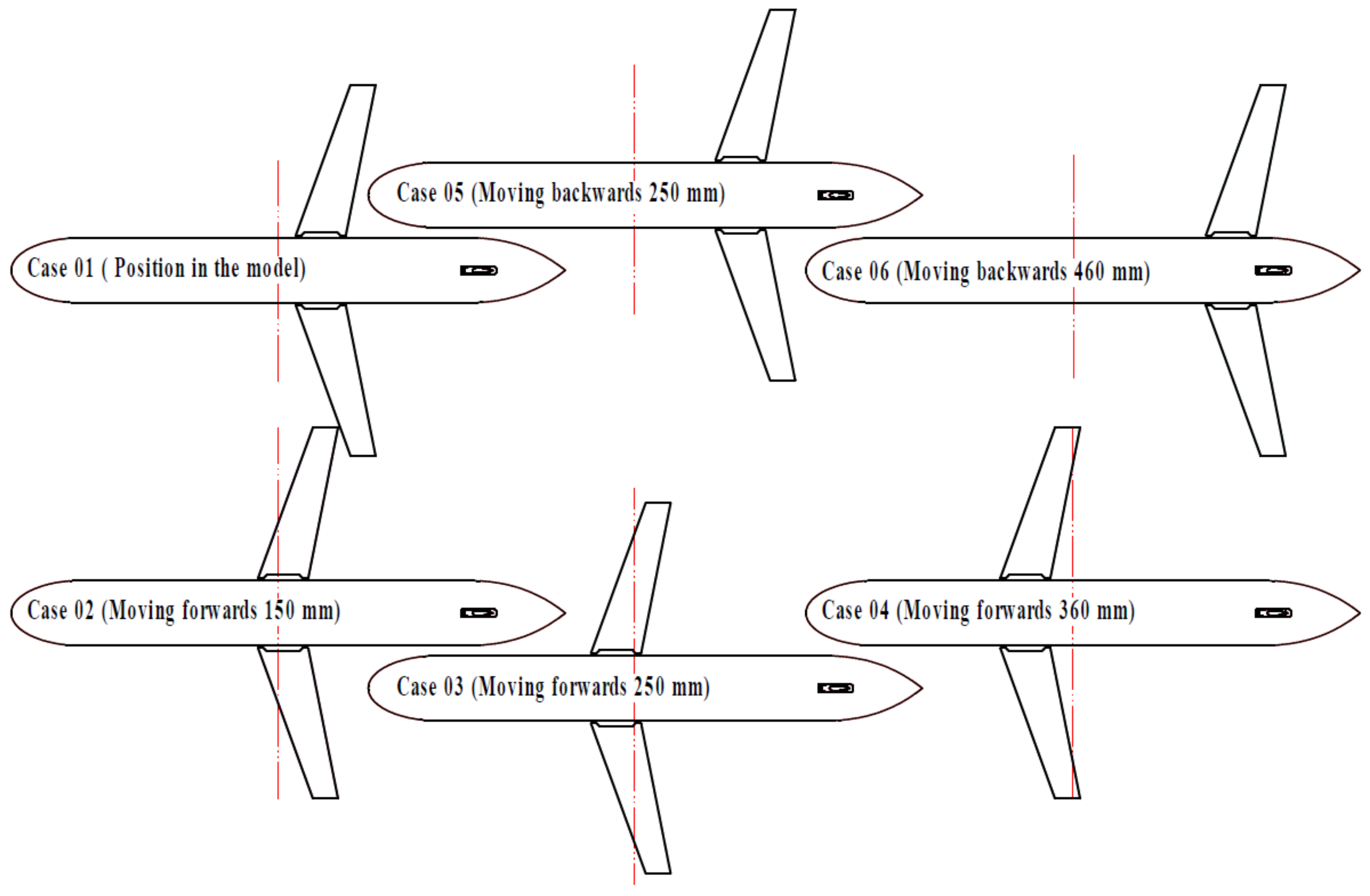
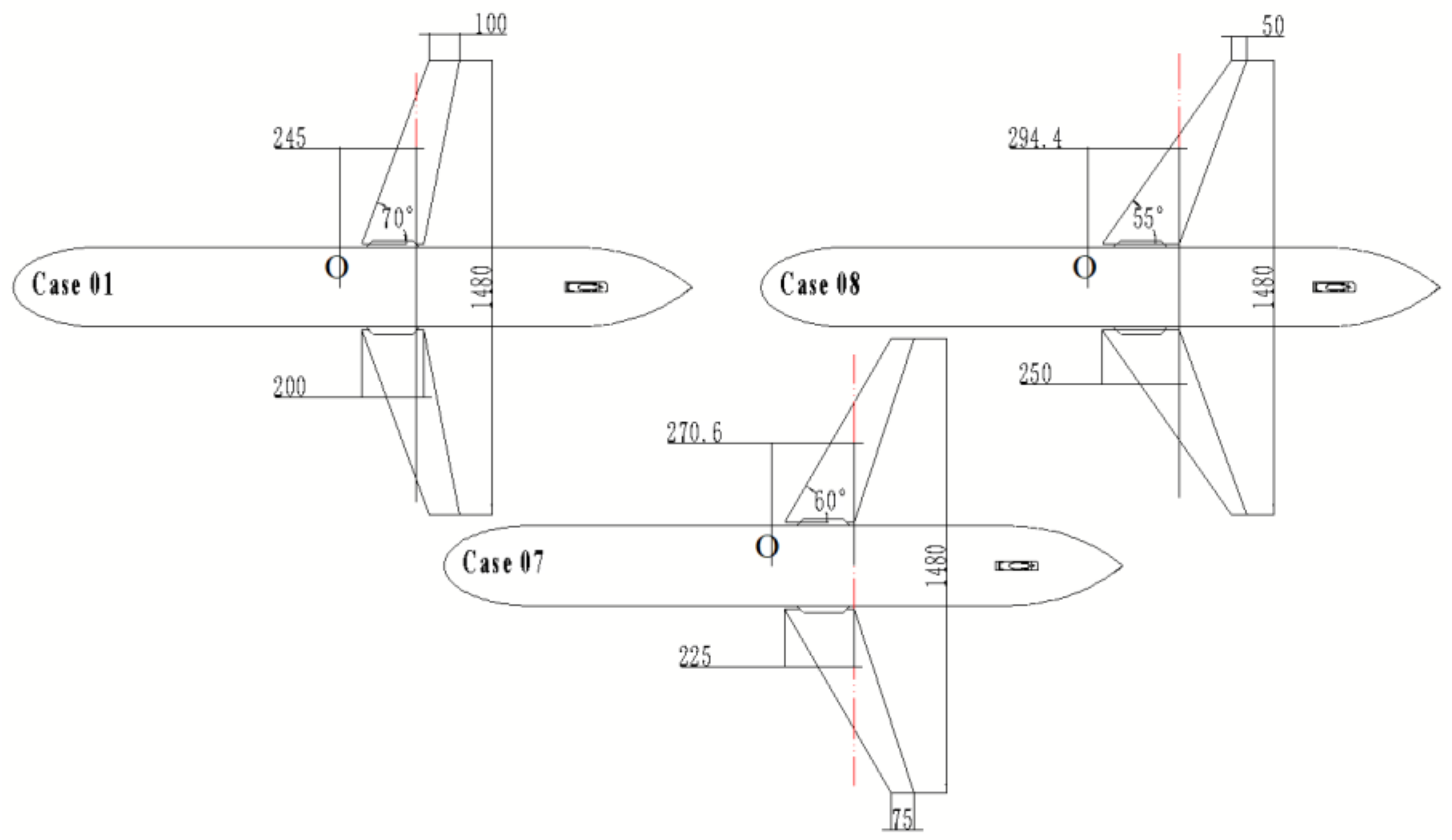
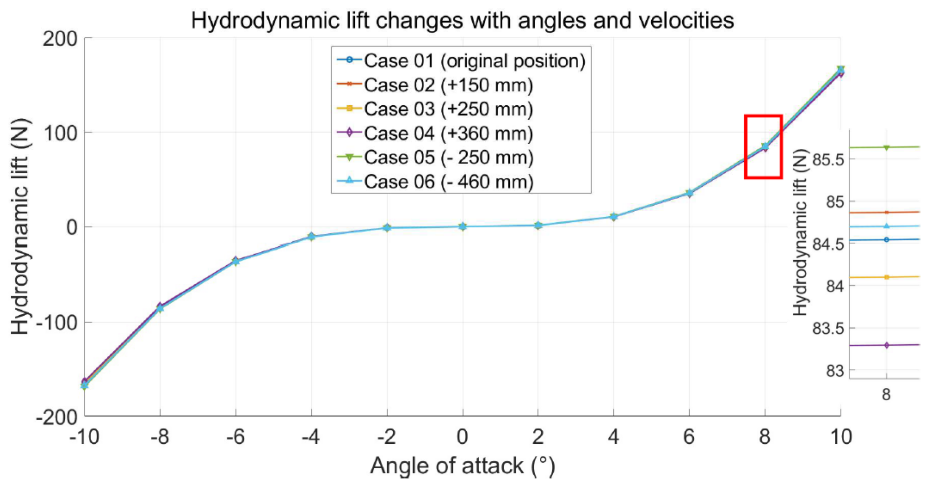
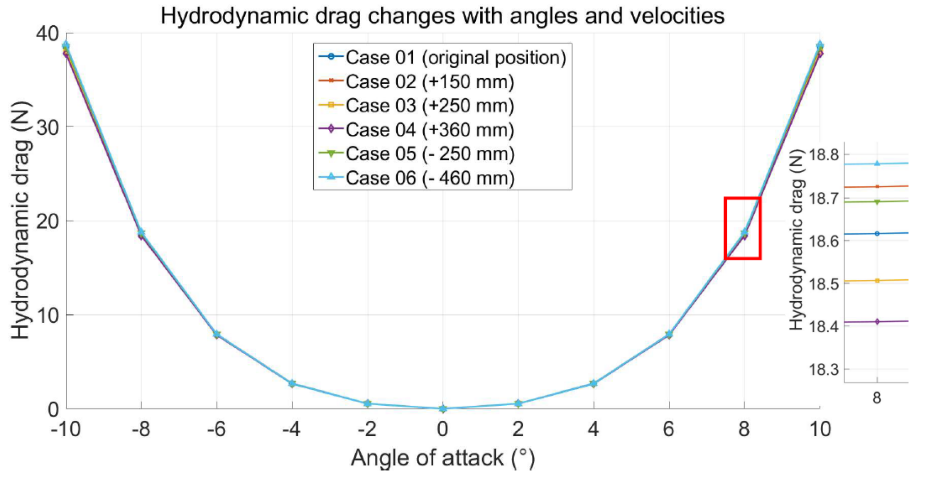
3. Wing Position and Shape Effect on Glide Motion

In this study, the effects of the wing position and shape on the glide velocity, angle, and path were analyzed. Because no analytical solution is available to determine the effect of the wing position and shape on the glider motion, an arranging method was used by selecting six wing positions, forward and backward of the buoyancy center, and three wing shapes. For the six wing positions displayed in Figure 5, the red double dotted line crosses the buoyancy center, and the three wing shapes in Figure 6, the glider model including parameters in [16] was used in computer simulation.
Six cases (Figure 5) are described as follows: Case 01 represents the glider model used in [16]. In Cases 02 and 03, the fixed wings were moved forward by 150 and 250 mm, respectively. In Case 04, the fixed wings were moved forward by 360 mm, and the buoyancy center coincided with the geometric center of the wing; in Case 05, the wing was positioned backward by 250 mm, and in Case 06, the wing was moved backward by 460 mm. Figure 5 displays the fixed wings in different positions. Their geometric centers of the fixed wings are at different distances from the red dotted line in the longitudinal direction, which leads to a difference in the magnitude and direction of the hydrodynamic moment caused by the fixed wings. When the geometric center of the fixed wing is located at a certain distance behind the buoyancy center, the hydrodynamic moment is in the same direction as the recovery moment of the glider; otherwise, it is in the opposite direction. The difference in the direction of the moment determines the scale of the glider pitch angle, which results in a difference in the gliding angle. The greater the distance between the fixed wing and buoyancy center is, the more apparent the change in the gliding angle is.
In Cases (Figure 6) 01, 07, and 08, the wingspan and surface area of the airfoil were maintained constant at various wing sweep angles, and these fixed wings with different airfoil parameters were mounted in the same position, as displayed in Figure 6. The dashed red line indicates the position of the point of action of the wing lift in the x-axis direction of the body coordinates. The distances from the floating center to the point of action of the force were 245, 270.6, and 294.4 mm in Cases 01, 07, and 08, respectively.
The hydrodynamic forces and moment were expressed as follows
L = K L 0 + K L α V 2
D = K D 0 + K D α 2 V 2
M D L = K M 0 + K M α V 2
where K s (contains K L 0 , K L , K D 0 , K D , K M 0 , and K M ) represent the hydrodynamic parameters, which were obtained using CFD and MATLAB, where α is the angle unit. The values of Ks are listed in Table 2 for cases 01–06, and Table 3 lists the values of Ks for 07, and 08.
The simulation speed conditions were set from 0.25 to 1.5 m/s, with an interval of 0.25 m/s. Based on Equations (31)–(33), the results of the hydrodynamic lift, hydrodynamic drag, and hydrodynamic moment for Cases 01–06 under various AOAs are displayed in Figure 7, Figure 8 and Figure 9. The red box represents the local zoomed-in area. Figure 7 and Figure 8 indicate that for all six cases of the position of the fixed wing relative to the buoyancy center in the glider assembly, the hydrodynamic lift and drag remained approximately the same within the AOA range (−8° to 8°) and within the cruising speed range of less than 1 m/s. The variation in the hydrodynamic moment, displayed in Figure 9, is evident.
For various AOA and velocity conditions based on Equations (31)–(33), the results of the hydrodynamic lift, hydrodynamic drag, and hydrodynamic moment for Cases 01, 07, and 08 are displayed in Figure 10, Figure 11 and Figure 12. The red box indicates the local zoom area. Figure 10 and Figure 11 display that the hydrodynamic lift and drag are similar in the AOA range (−8° to 8°) and cruising speed less than 1 m/s, whereas the variation in the hydrodynamic moment is significant, as displayed in Figure 12. These results revealed that the hydrodynamic lift and drag decreased when the sweep angle decreased. However, the change in the airfoil shape caused the geometric center of the fixed wing to move away from the buoyancy center, which resulted in a tendency for the hydrodynamic moment to increase.
Based on the aforementioned simplified equations of glider motion, the gliding speed and angle were simulated for six cases under the same displacement of the movable mass block and piston. Furthermore, the presented glide path is the maximum permissible for the glider structure. Figure 13, Figure 14 and Figure 15 display the simulation results.
In Figure 13, Case 06 exhibits the fastest gliding speed for the same input conditions, and the comparison results of the gliding angle in Figure 14 reveal that the glider in Case 06 exhibits a larger range of gliding angles than those in other cases. Compared with the glide trajectory, the glider in Case 06 exhibited a larger dive depth and glide distance when the inputs were the same for all cases.
Figure 16 displays a comparison of the glide paths of the three cases (Cases 01, 07, and 08). According to the results, the glide path exhibited an increasing trend as the sweeping angle decreased.
When the glider is moving underwater in a steady state at a speed of 0.4 m/s, the gliding angle is + or −25°. Here, +25° indicates that the glider is in the surfacing stage; otherwise, it is in the diving stage. As presented in Table 4, the movable mass block in Case 06 exhibited the smallest moving displacement when the glide paths of the gliders were the same.
Figure 17 shows the comparison of the glide depth of the glider in the stable gliding condition, and the control inputs are the parameters in Table 4. Considering the transformation of the glider from steady-state dive to steady-state surfacing, the displacements of the mass block and piston for each case were obtained from Table 4. The displacement of the piston and dive depth were approximately equal in each case, and the work required to overcome the seawater pressure was approximately the same for the same buoyancy engine mechanism. The work performed by the mass shifter on the mass block in the glider is expressed as follows:
P = F S
where F is the force driving the movement of the mass block in the direction of the longitudinal axis of the glider, and S is the displacement of the mass block. For the same mass shifter, the forces F are equal. Subsequently, the ratio of the work on the masses in each case was equal to the ratio of the displacement of the respective masses. The ratio of work is expressed as follows:
P c a s e 01 : P c a s e 02 : P c a s e 03 : P c a s e 04 : P c a s e 05 : P c a s e 06                      = 7.924 : 8.829 : 9.384 : 10.253 : 6.248 : 4.974
The work ratio reveals that Case 06 requires the least amount of energy versus Case 04, and Case 06 will save approximately 51% of the energy.
When the gliding angle is around 35° [17,18,19,20], the underwater glider will realize the maximum gliding speed, and the maximum design gliding speed of the glider in this paper is 2 knots. Due to the limitation of the structure space, the displacement range of the movable mass block is plus or minus 0.08 m, and the piston of the buoyancy engine moves within plus or minus 0.1 m. The following simulation input data were obtained from the simulation of cases 01 to 06, as shown in Table 5. From the control inputs in Table 5, it can be found that in cases 03 and 04, even though the control inputs are maximum, the speed and angle requirements are still not achieved. The comparison of cases 01, 02, 05 and 06 shows that the displacement of the piston in case 06 is less than or equal to the input of the other cases, yet the movable mass block has the smallest displacement and the negative sign indicates the backward movement. Case 06 has the smallest energy consumption when they need to reach a glide angle of 35 having the maximum glide speed. Due to the symmetry of the glider motion, only the parameters at the down dive state are given here.

4. Linearization of the Equations of Motion near the Operating Point

Because UG control is highly complex, and most operations of the glider involve steady-state diving or surfacing, nonlinear equations of motion were linearized [20,21,22,23]. The linearized equations of motion are only valid enough for a small range around the equilibrium point and do not characterize the entire control phase. The vertical glide motion achieves a steady equilibrium point, and the parameters are as follows: the gliding speed is 0.4 m/s, the gliding angle is +25° or −25°.
Let states z = z , θ , ω 2 , v 1 , v 3 T and control inputs u = d m 1 , d p 1 T , where z measures the position of the glider perpendicular to the desired path [1]. Defining δ z = z z d and δ u = u u d , the initial values of δ z and δ u are set to 0.
Then the linearized system is
δ z ˙ = A δ z + B u
where
A = 0 v d 0 sin α d cos α d 0 0 1 0 0 0 a 32 a 33 a 34 a 35 0 a 42 a 43 a 44 a 45 0 a 52 a 53 a 54 a 55
B = 0 0 0 0 1 J m ¯ g cos θ d b 32 0 1 m 1 + m ¯ + m p ρ π r 2 g sin θ d 0 1 m 3 + m ¯ + m p ρ π r 2 g cos θ d
a 32 = m g J r r x d sin θ d r r z d cos θ d a 33 = 1 J m ¯ r m ¯ 1 d v 1 d + m p r p 1 d v 1 d + m ¯ r m ¯ 3 v 3 d + m p r p 3 v 3 d a 34 = 1 J m 3 m 1 v 3 d + M v 1 | e q a 35 = 1 J m 3 m 1 v 1 d + M v 3 | e q a 42 = m 0 d m 1 + m ¯ + m p g cos θ d   a 43 = 1 m 1 + m ¯ + m p m 3 + m ¯ + m p v 3 d   a 44 = 1 m 1 + m ¯ + m p L v 1 sin α d + L cos α d α v 1 D v 1 cos α d + D sin α d α v 1 | e q a 45 = 1 m 1 + m ¯ + m p L v 3 sin α d + L cos α d α v 3 D v 3 cos α d + D sin α d α v 3 | e q a 52 = 1 m 3 + m ¯ + m p m 0 d g sin   θ d a 53 = 1 m 3 + m ¯ + m p m 1 + m ¯ + m p v 1 d a 54 = 1 m 3 + m ¯ + m p L v 1 cos α d + L sin α d α v 1 D v 1 sin α d D cos α d α v 1 | e q a 55 = 1 m 3 + m ¯ + m p L v 3 cos α d + L sin α d α v 3 D v 3 sin α d D cos α d α v 3 | e q
here, L v 1 , D v 1 , α v 1 , L v 3 , D v 3 , α v 3 , M v 1 | e q and M v 3 | e q were presented in [1].
b 32 = 1 J m g m p m + ρ π r 2 r b i + 1 2 m b i M B m b i + ρ π r 2 M B m b i d p 1 d cos θ d + r b 3 ρ π r 2 M B m b i sin θ d
Figure 18, Figure 19, Figure 20 and Figure 21 display the simulation results for the open- and closed-loop for Cases 01–06, Figure 18 and Figure 19 detail the responses of the pitch angle ( δ θ ) and longitudinal velocity ( δ v 1 ) after setting a target and assigning inputs to individual cases. All cases eventually reach a steady state, and Case 04 is the first to reach the steady state. Figure 20 and Figure 21 illustrate the response states of the aforementioned angle and velocity under the action of a proportional–integral–derivate (PID) controller. Figure 20 displays the pitch angle ( δ θ ) response for a disturbance, and the response trend was similar for all cases. The figure reveals that the controller can control the transient mode resulting from disturbances. Furthermore, the results in Figure 20 and Figure 21 represent that the position of the fixed wing did not affect the glider control response. Because of the approximate symmetry of the dive and surfacing, control simulations were performed only for the dive phase.
Figure 22, Figure 23, Figure 24 and Figure 25 detail the simulation results for open and closed loop for Cases 01, 07, and 08. Figure 22 and Figure 23 reflect the responses of the pitch angle ( δ θ ) and longitudinal velocity ( δ v 1 ) after setting a target and assigning various inputs to individual cases. The three cases exhibited similar behavior. Figure 24 and Figure 25 illustrate the response of the UG in terms of angle and velocity because of the action of the controller. Figure 24 displays the response state of the pitch angle ( δ θ ) for a disturbance. The response trend is similar for each case. The controller can control the operating state of the glider satisfactorily even if the disturbance is present. The shape of the fixed wing did not affect the glider control response, as displayed in Figure 24 and Figure 25. Because of the approximate symmetry of dive and surfacing, control simulations were performed only for the dive phase.

5. Discussion

In this study, the motion model of the underwater glider was reconstructed by the method of function elimination and minimal value omission, and it was concluded from the simulation results that the reconstructed simplified model is basically consistent with the results of the original model.
In Section 3, the influence of the fixed wing of the underwater glider on the gliding parameters in different mounting positions and the comparison of the energy consumption in different cases were described in detail. From the simulation results shown in Figure 13, Figure 14 and Figure 15, it can be seen that when the fixed wing was in the tail of the glider and the control inputs were the same, the glider had stronger gliding speed, larger gliding angle and wider working space. In reference [18], a new high-speed underwater glider is designed and studied, which has a fixed wing mounted at the rear of the body and a small swept-back angle of the wing. This wing structure and installation position fully validate the conclusion of this paper, that is, the glider with the fixed wing installed at the tail and the wing swept-back angle is smaller has a strong gliding capability. The contents of Table 4 and Figure 17 revealed that when cases 01 to 06 have the same gliding parameters, a comparison of the energy required for the glider attitude change yielded that the glider with the fixed wing at the tail was able to save energy effectively. The data in Table 5 indicated the control input parameters required when the gliding angle of each case glider was around 35° and the glider reached the maximum gliding speed. This result can also well illustrate that the glider needs a smaller control input to achieve the maximum gliding speed when the fixed wing is at the tail. The smaller the control input, the less energy is consumed. According to the comparison of glide paths in Figure 16, it can be seen that the glider with a smaller wing swept-back angle has a stronger gliding capability under the condition of constant wing area and wingspan. The contents in Figure 22, Figure 23, Figure 24 and Figure 25 show that changing only the swept-back angle of the airfoil at the same installation position, with the airfoil area and wingspan kept constant, results in an enhancement in the gliding parameters, however, there is no particularly significant effect on the state response of the system. As mentioned in the second part of the paper, as shown in Figure 3, when the geometric center of the fixed wing is somewhere behind the buoyancy center, the hydrodynamic moment always keeps the same direction as the recovery moment of the glider during the glider’s dive or uplift phase. The farther the geometric center of the fixed wing is from the buoyancy center, the larger the hydrodynamic moment is.
Linearization is performed at a specified steady glide state to study the glider near a certain equilibrium point. Verified the dynamic response of the gliders in cases 01 to 06 by simple PID control. The conclusions point out that the control response results were similar for gliders with different fixed wing positions, with no particularly significant differences. This paper mainly studied the piston type underwater glider, whether it is applicable to the bladder type underwater glider needs further verification

6. Conclusions

In this study, a simplified glider dynamics model that explicitly expresses the control inputs was developed to analyze glider dynamics. Computer simulations revealed that the simplified dynamics model can replace the original nonlinear model.
In this study, the effects of the wing position and wing shape on the motion of the UG were investigated. Because direct analytic approach cannot be performed, a case study of the effects of six wing positions and three wing shapes on gliding performance were investigated through computer simulation. During the gliding state transition, the wing positioned farthest from the tail end from the buoyancy center consumed the least amount of energy and achieved approximately 51% energy savings compared with that far away from the buoyancy center to the head. These cases study revealed that the working-space range of the glider increased as the distance from the fixed wing to the buoyancy center increased. Furthermore, a simulation comparison of various airfoil cases revealed that when the airfoil swept back angle decreased, the working range of the glider tended to increase. From the simulation results of the cases in the text, Case 06 and Case 08 are the best, that is, the wing has a smaller swept-back angle and is mounted at the aft end away from the buoyancy center.
Investigations of the transient mode of the UG revealed that the position of the wing and its shape did not considerably affect UG behavior. In order to verify the state response at different positions of the fixed wings, the PID controller was used to determine the position of the mass shifter and piston for controlling the transient behavior of the UG. The results obtained in this paper will then be applied to a study of a two-body glider to check if the same results can be achieved in other different systems.

Author Contributions

Conceptualization, H.-S.C., M.T.V. and J.H.; methodology, J.H.; software, J.H.; validation, M.T.V., J.H., H.-J.C., J.-H.P., J.-Y.K., K.-B.C., D.-W.J., P.H.N.A., R.Z. and H.N.T.; formal analysis, J.H. and D.-W.J.; investigation, J.H. and J.-Y.K.; resources, J.H. and H.-S.C.; data curation, J.H.; writing—original draft preparation, J.H.; writing—review and editing, M.T.V., D.-W.J., H.-J.C., J.-H.P., J.-Y.K., K.-B.C., R.Z., H.-S.C. and H.N.T.; supervision, H.-S.C.; project administration, H.-S.C.; funding acquisition, H.-S.C. All authors have read and agreed to the published version of the manuscript.

Funding

This research was supported by “Data Collection System with Underwater Glider (19AR0001)” funded by the Agency for Defense Development and also was supported by AUV Fleet and its Operation System Development for Quick Response of Search on Marine Disasters of Korea Institute of Marine Science & Technology Promotion(KIMST) funded by the Korea Coast Guard Agency (KIMST-20210547).

Institutional Review Board Statement

Not applicable.

Informed Consent Statement

Not applicable.

Data Availability Statement

Not applicable.

Acknowledgments

The authors acknowledge all members of the Korea Maritime University Intelligent Robot & Automation Lab.

Conflicts of Interest

The authors declare no conflict of interest.

References

  1. Graver, J.G. Underwater Gliders: Dynamics, Control and Design. Ph.D. Thesis, Princeton University, Candidacy, NJ, USA, 2005. [Google Scholar]
  2. Hussain, N.A.A.; Arshad, M.R.; Mohd-Mokhtar, R. Underwater glider modelling and analysis for net buoyancy, depth and pitch angle control. Ocean. Eng. 2011, 38, 1782–1791, ISSN 0029-8018. [Google Scholar] [CrossRef]
  3. Ji, D.H.; Choi, H.S.; Kang, J.I.; Cho, H.J.; Joo, M.G.; Lee, J.H. Design and control of hybrid underwater glider. Adv. Mech. Eng. 2019, 11, 1–9. [Google Scholar] [CrossRef]
  4. Joo, M.G.; Qu, Z. An autonomous underwater vehicle as an underwater glider and its depth control. Int. J. Control Autom. Syst. 2015, 13, 1212–1220. [Google Scholar] [CrossRef]
  5. Isa, K.; Arshad, M.R. Vertical motion simulation and analysis of USM underwater glider. In Proceedings of the 5th International Conference on Automation, Robotics and Applications, Wellington, New Zealand, 6–8 December 2011; pp. 139–144. [Google Scholar] [CrossRef]
  6. Zihao, W.; Ye, L.; Aobo, W.; Xiaobing, W. Flying wing underwater glider: Design, analysis, and performance prediction. In Proceedings of the 2015 International Conference on Control, Automation and Robotics, Colmar, France, 21–23 July 2015; pp. 74–77. [Google Scholar] [CrossRef]
  7. Haitao, G.U.; Yang, L.I.N.; Zhiqiang, H.U.; Jiancheng, Y.U. Surrogate Models Based Optimization Methods for the Design of Underwater Glider Wing. J. Mech. Eng. 2009, 45, 7–14. [Google Scholar] [CrossRef]
  8. Javaid, M.Y.; Ovinis, M.; Hashim, F.B.; Maimun, A.; Ahmed, Y.M.; Ullah, B. Effect of wing form on the hydrodynamic characteristics and dynamic stability of an underwater glider. Int. J. Nav. Archit. Ocean. Eng. 2017, 9, 382–389. [Google Scholar] [CrossRef] [Green Version]
  9. Meyers, L.M.; Msomi, V. Hydrodynamic analysis of an underwater glider wing using ANSYS fluent as an investigation tool. Mater. Today Proc. 2021, 45, 5456–5461. [Google Scholar] [CrossRef]
  10. Xu, S.; Liu, Y.; Zhu, Y.; Wang, Y. Effects of Airfoil on Flight Performance of Autonomous Underwater Gliders. China Mech. Eng. 2017, 28, 286. [Google Scholar]
  11. Singh, Y.; Bhattacharyya, S.K.; Idichandy, V.G. CFD approach to modelling, hydrodynamic analysis and motion characteristics of a laboratory underwater glider with experimental results. J. Ocean. Eng. Sci. 2017, 2, 90–119, ISSN 2468-0133. [Google Scholar] [CrossRef]
  12. Lyu, D.; Song, B.; Pan, G.; Yuan, Z.; Li, J. Winglet effect on hydrodynamic performance and trajectory of a blended-wing-body underwater glider. Ocean. Eng. 2019, 188, 106303. [Google Scholar] [CrossRef]
  13. Javaid, M.Y.; Ovinis, M.; Hashim, F.B.M.; Maimun, A.; Ali, S.S.A.; Ahmed, S.A. Investigation on the dynamic stability of an underwater glider using CFD simulation. In Proceedings of the 2016 IEEE International Conference on Underwater System Technology: Theory and Applications (USYS), Penang, Malaysia, 13–14 December 2016; pp. 230–235. [Google Scholar] [CrossRef]
  14. Liu, F.; Wang, Y.; Niu, W.; Ma, Z.; Liu, Y. Hydrodynamic performance analysis and experiments of a hybrid underwater glider with different layout of wings. In Proceedings of the Oceans 2014–Taipei, Taipei, Taiwan, 7–14 April 2014. [Google Scholar]
  15. Wang, Y.; Zhang, Y.; Zhang, M.; Yang, Z.; Wu, Z. Design and flight performance of hybrid underwater glider with controllable wings. Int. J. Adv. Robot. Syst. 2017, 14, 172988141770356. [Google Scholar] [CrossRef] [Green Version]
  16. Huang, J.; Choi, H.-S.; Jung, D.-W.; Lee, J.-H.; Kim, M.-J.; Choo, K.-B.; Cho, H.-J.; Jin, H.-S. Design and Motion Simulation of an Underwater Glider in the Vertical Plane. Appl. Sci. 2021, 11, 8212. [Google Scholar] [CrossRef]
  17. Eichhorn, M.; Aragon, D.; Shardt, Y.A.; Roarty, H. Modeling for the performance of navigation, control and data post-processing of underwater gliders. Appl. Ocean. Res. 2020, 101, 102191, ISSN 0141-1187. [Google Scholar] [CrossRef]
  18. Jo, S.; Jeong, S.; Choi, H.; Jeong, D. Design of a new high speed unmanned underwater glider and motion control. In Proceedings of the Oceans 2016–Shanghai, Shanghai, China, 10–13 April 2016; pp. 1–6. [Google Scholar] [CrossRef]
  19. Jeong, S.K.; Choi, H.S.; Bae, J.H.; You, S.S.; Kang, H.S.; Lee, S.J.; Kim, J.Y.; Kim, D.H.; Lee, Y.K. Design and control of high speed unmanned underwater glider. Int. J. Precis. Eng. Manuf.-Green Technol. 2016, 3, 273–279. [Google Scholar] [CrossRef]
  20. Da Silva Tchilian, R.; Rafikova, E.; Gafurov, S.A.; Rafikov, M. Optimal Control of an Underwater Glider Vehicle. Procedia Eng. 2017, 176, 732–740, ISSN 1877-7058. [Google Scholar] [CrossRef]
  21. Mahmoudian, N.; Woolsey, C. Underwater glider motion control. In Proceedings of the 2008 47th IEEE Conference on Decision and Control, Cacun, Mexico, 9–11 December 2008; pp. 552–557. [Google Scholar] [CrossRef]
  22. Leonard, N.E.; Graver, J.G. Model-based feedback control of autonomous underwater gliders. IEEE J. Ocean. Eng. 2001, 26, 633–645. [Google Scholar] [CrossRef] [Green Version]
  23. Latifa, U.; Putri, T.W.O.; Trilaksono, B.R.; Hidayat, E.M.I. Modelling, identification, and simulation of autonomous underwater glider in longitudinal plane for control purpose. In Proceedings of the 2017 2nd International Conference on Control and Robotics Engineering (ICCRE), Bangkok, Thailand, 1–3 April 2017; pp. 140–144. [Google Scholar] [CrossRef]
Figure 1. Developed glider and schematic diagram of glider components [16].
Jmse 10 00891 g001
Figure 2. Body coordinate.
Jmse 10 00891 g002
Figure 3. Steady state of the glider during diving and floating.
Jmse 10 00891 g003
Figure 4. Glide path of original model and simplified model.
Jmse 10 00891 g004
Figure 5. Schematic diagram of relationship between fixed wing and buoyancy center position.
Jmse 10 00891 g005
Figure 6. Various wing types.
Jmse 10 00891 g006
Figure 7. Variation in the hydrodynamic lift according to angles and velocities.
Jmse 10 00891 g007
Figure 8. Variation in the hydrodynamic drag according to angles and velocities.
Jmse 10 00891 g008
Figure 9. Variation in the hydrodynamic moment with angles and velocities.
Jmse 10 00891 g009
Figure 10. Changes in the hydrodynamic lift with angles and velocities.
Jmse 10 00891 g010
Figure 11. Changes in the hydrodynamic drag with angles and velocities.
Jmse 10 00891 g011
Figure 12. Changes in the hydrodynamic moment with angles and velocities.
Jmse 10 00891 g012
Figure 13. Simulation results of the gliding velocity.
Jmse 10 00891 g013
Figure 14. Simulation results of the gliding angle.
Jmse 10 00891 g014
Figure 15. Simulation results of the gliding path.
Jmse 10 00891 g015
Figure 16. Simulation results of the gliding path in Cases 01, 07, and 08.
Jmse 10 00891 g016
Figure 17. Gliding depth with same gliding parameters.
Jmse 10 00891 g017
Figure 18. Responses of the pitching Angle ( δ θ ) (open loop).
Jmse 10 00891 g018
Figure 19. Response of the longitudinal velocity ( δ v 1 ) (open loop).
Jmse 10 00891 g019
Figure 20. Response of the pitching Angle ( δ θ ) with controller.
Jmse 10 00891 g020
Figure 21. Response of the longitudinal velocity ( δ v 1 ) with controller.
Jmse 10 00891 g021
Figure 22. Responses of the pitching Angle ( δ θ ) (open loop) (cases 01, 07 and 08).
Jmse 10 00891 g022
Figure 23. Response of the longitudinal velocity ( δ v 1 ) (open loop) (cases 01, 07 and 08).
Jmse 10 00891 g023
Figure 24. Response of the pitching Angle ( δ θ ) with controller (cases 01, 07 and 08).
Jmse 10 00891 g024
Figure 25. Response of the longitudinal velocity ( δ v 1 ) with controller (cases 01, 07 and 08).
Jmse 10 00891 g025
Table 1. Descriptions of parameters of above equations.
TermDescription
x The horizontal displacement in the vertical plane
z The vertical displacement in the vertical plane
v 1 The velocity of glider along the x-axis in the body-fixed frame
v 3 The velocity of glider along the z-axis in the body-fixed frame
θ The angle of pitch
ω 2 The pitch angular velocity rotating about the y-axis of the body-fixed frame
m 1 The mass of glider (with added mass) in x-axis
m 3 The mass of glider (with added mass) in z-axis
p m ¯ 1 The momenta of moveable mass along x-axis
p m ¯ 3 The momenta of moveable mass along z-axis
p p 1 The momenta of piston along x-axis
p p 3 The momenta of piston along z-axis
m 0 Net buoyancy mass
L Hydrodynamic lift
D Hydrodynamic drag
α Angle of attack
u m ¯ 1 The force acting on the moveable mass in the x-direction
u m ¯ 3 The force acting on the moveable mass in the z-direction
u p 1 The force acting on the piston in the x-direction
u p 3 The force acting on the piston in the z-direction
J 2 The moment of inertia rotating about the y-axis (without moveable mass and piston)
r m ¯ 1 Position of moveable mass in the x direction
r m ¯ 3 Position of moveable mass in the z direction
r p 1 Position of piston in the x direction
r p 3 Position of piston in the z direction
m Mass of the glider
r r x Position of gravity center in the x direction
r r z Position of gravity center in the z direction
M D L Hydrodynamic moment
d m ¯ 1 The displacement of moveable mass along x direction
d p 1 The displacement of piston along x direction
u 0 The ballast water per meter
ζ Gliding angle
m ¯ Mass of moveable mass
m p Mass of piston
J The total moment of inertia of glider rotating about the y-axis
r m ¯ i Initial position of movable mass along x-axis
r p i Initial position of piston along x-axis
m s Mass of static equilibrium
m b i Initial mass of ballast in neutral state
r b i Initial position of ballast water along x-axis (equilibrium)
ρ Density of water
r Radius of piston
M B Maximum buoyancy of glider
r m 3 ¯ Position of moveable mass in the z direction
r p 3 Position of piston in the z direction
r s 3 Position of static equilibrium mass in the z direction
r b 3 Position of ballast water in the z direction
Table 2. Values of Ks for Case 01-Case 06.
K L 0 K L K D 0 K D K M 0 K M
Case 01−0.193410.59227.97960.16620.148−0.5864
Case 02−0.263410.64138.15970.16510.18240.8145
Case 03−0.096310.56088.08090.16320.16141.7979
Case 04−0.115210.42618.18310.15980.1342.8886
Case 05−0.302710.74268.11820.16520.2274−3.1496
Case 06−0.555410.6578.06420.16740.4025−5.10375
Table 3. Values of Ks for Case 07 and Case 08.
K L 0 K L K D 0 K D K M 0 K M
Case 07−0.109110.32088.06970.15630.1597−0.737
Case 08−0.214410.28417.96190.15660.1747−0.9321
Table 4. Parameters of d m 1 and d p 1 for Case 01-Case 06 (units: m).
Case 01Case 02Case 03Case 04Case 05Case 06
Diving d p 1 0.018520.018960.018740.0190.018830.01878
d m 1 0.040360.045220.048580.052550.031630.02498
Surfacing d p 1 −0.01847−0.01889−0.01872−0.01897−0.01875−0.01864
d m 1 −0.03888−0.04307−0.04626−0.04998−0.03085−0.02476
Table 5. Parameters for cases 01 to 06 at maximum gliding speed.
d p 1 (m) d m 1 (m)Glide Angle (°)Glide Velocity (m/s)
Case 010.0870.0605−35.11.0295
Case 020.0930.08−33.781.033
Case 030.10.08−26.50.9535
Case 040.10.08−17.70.7464
Case 050.0870.024−361.033
Case 060.087−0.004−35.81.032
Publisher’s Note: MDPI stays neutral with regard to jurisdictional claims in published maps and institutional affiliations.

