Article

Dexterity Based Viscous Resistance Optimization of a Deep-Sea Manipulator

1
State Key Laboratory of Robotics, Shenyang Institute of Automation, Chinese Academy of Sciences, Shenyang 110016, China
2
Institutes for Robotics and Intelligent Manufacturing, Chinese Academy of Sciences, Shenyang 110169, China
3
Key Laboratory of Marine Robotics, Shenyang 110169, China
4
University of Chinese Academy of Sciences, Beijing 100049, China
5
Southern Marine Science and Engineering Guangdong Laboratory, Guangzhou 511458, China
*
Author to whom correspondence should be addressed.
J. Mar. Sci. Eng. 2022, 10(7), 876; https://doi.org/10.3390/jmse10070876
Submission received: 23 May 2022 / Revised: 24 June 2022 / Accepted: 24 June 2022 / Published: 26 June 2022
(This article belongs to the Special Issue Advances in Marine Vehicles, Automation and Robotics)

Abstract

:
With persistent ocean exploration, the complexity of deep-sea intervention is gradually increasing. The deep-sea manipulator is the primary tool to complete complex intervention. The manipulator dexterity determines the complexity of the task it can perform. First, a dynamic dexterity evaluation method is proposed based on the kinematics and dynamics characteristics of the deep-sea manipulator. This method takes into account the dynamic torque boundary and Jacobian mapping constraint, which are different from terrestrial manipulators. The concepts of the dynamic dexterity ellipsoid and dynamic dexterity measure are defined. Second, the effect of viscosity resistance on dexterity is analyzed. The viscosity resistance is optimized by selecting the most suitable compensation oil. Finally, the methods of dynamic dexterity evaluation and viscosity resistance optimization are verified by a simulated deep-sea experiment. The method proposed in this paper effectively improves the dynamic dexterity of the deep-sea manipulator by optimizing the viscosity resistance. The proposed method can also be used to evaluate and improve the dexterity of other underwater manipulators.

1. Introduction

With further study of ocean exploration, underwater intervention tasks have gradually become more complex, and the dexterity of underwater robots is being studied. Typical examples of this type of robot include Ocean One [1], TRIDENT I-AUV [2], Aquanaut [3], and Haidou I [4] (Figure 1). This kind of robot breaks through the working mode of traditional underwater robots and has higher dexterity when performing underwater intervention tasks.
These types of robots are equipped with one or more underwater manipulators to execute underwater intervention tasks. The dexterity of the underwater manipulator largely determines the intervention ability of these types of underwater robots. At present, underwater manipulators can be divided into hydraulic manipulators and electric manipulators according to the driving mode, and both of them have mature commercial products [5]. However, the performance indicators of underwater manipulators are still relatively simple, such as the degree of freedom, load capacity, weight, and arm length, and there is no quantitative index to evaluate the dexterity of an underwater manipulator.
Figure 2 shows the deep-sea 6 d.o.f. electric manipulator developed by Shenyang Institute of Automation, Chinese Academy of Sciences [6,7]. This deep-sea manipulator has been attached to the Haidou I underwater robot to complete many intervention tasks on the seabed of the Mariana Trench and has been used to complete intervention at depths of more than 10,000 m for the first time in the world. However, as the designer of this deep-sea electric manipulator, we know only its basic performance indicators [8], and there is no way to quantitatively evaluate its dexterity.
In terms of the dexterity evaluation of the manipulator, current research mainly focuses on the dexterity of industrial robots [9,10,11], and there are few related studies on the dexterity of deep-sea manipulators [12,13,14]. The dexterity evaluation is usually based on the kinematics or dynamics model of the manipulator [15,16]. Due to the particular operating environment of the deep-sea manipulator, it is not accurate to evaluate its dexterity using the existing methods, and the dexterity of the deep-sea manipulator needs to be studied comprehensively from the two aspects of kinematics and dynamics.
The deep-sea manipulator is filled with insulating oil to compensate for the external water pressure, but this causes the motor and reducer of the joint to rotate in the oil, creating additional viscosity resistance [17,18]. Some experiments show that the viscosity resistance obviously reduces the dynamic performance of the deep-sea manipulator [19,20]. Based on the theory of viscosity hydrodynamics, some previous work has studied the modelling of viscosity resistance, but is has not tried to give optimization methods [21,22].
This paper takes the deep-sea electric manipulator shown in Figure 2 as the research object and proposes a method of dexterity-based viscous resistance optimization. The main contributions of this paper are as follows:
(1)
A dynamic dexterity evaluation method of the deep-sea manipulator is proposed. This method considers the kinematic and dynamic characteristic of the deep-sea manipulator.
(2)
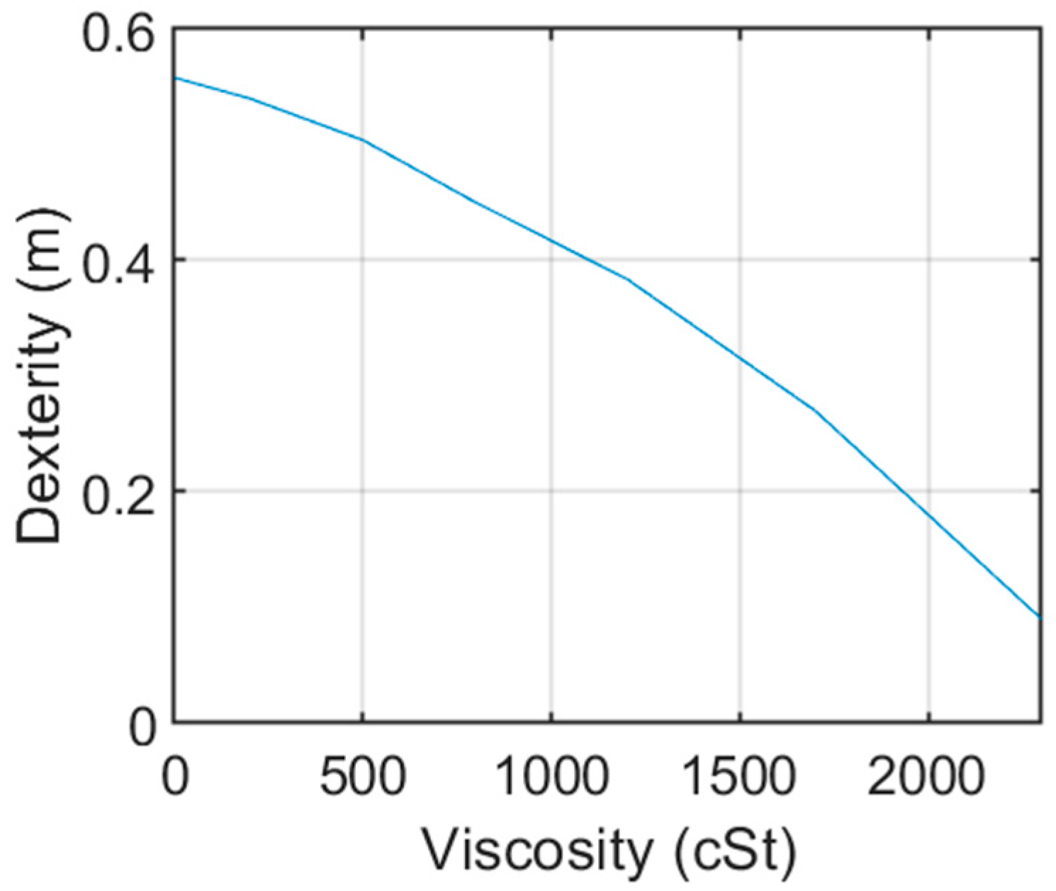
The effect of compensating oil viscosity on dexterity is studied. A practical viscous resistance optimization method is proposed.
(3)
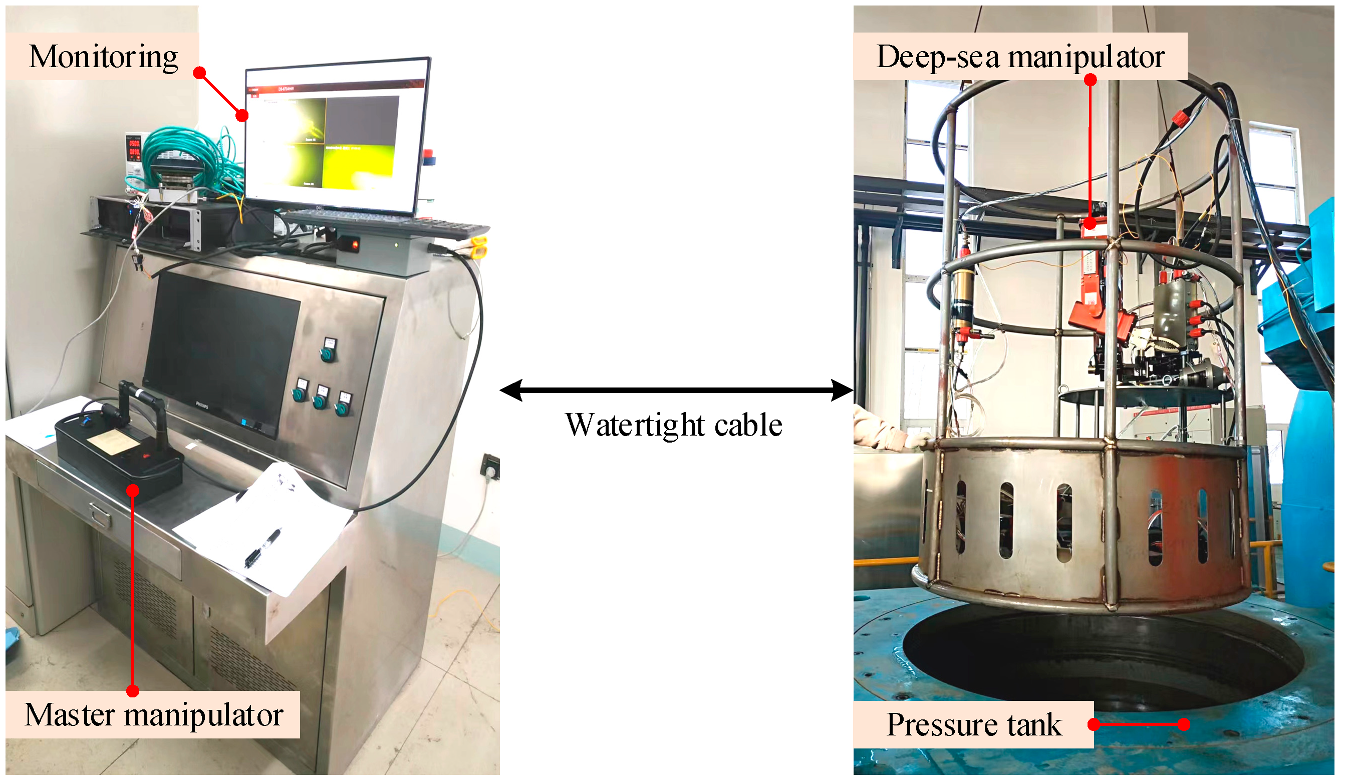
The method proposed in this paper is verified by a simulated deep-sea experiment.
The main research contents of this paper include the following: In Section 2, the kinematic and dynamic models of the deep-sea electric manipulator are established. In Section 3, a dynamic dexterity evaluation method with dynamic torque boundary and Jacobian mapping constraint is proposed based on the dynamic model. In Section 4, a viscosity resistance optimization method is proposed based on dynamic dexterity. In Section 4, a simulated deep-sea experiment is used to verify the proposed method.

2. Mathematical Model

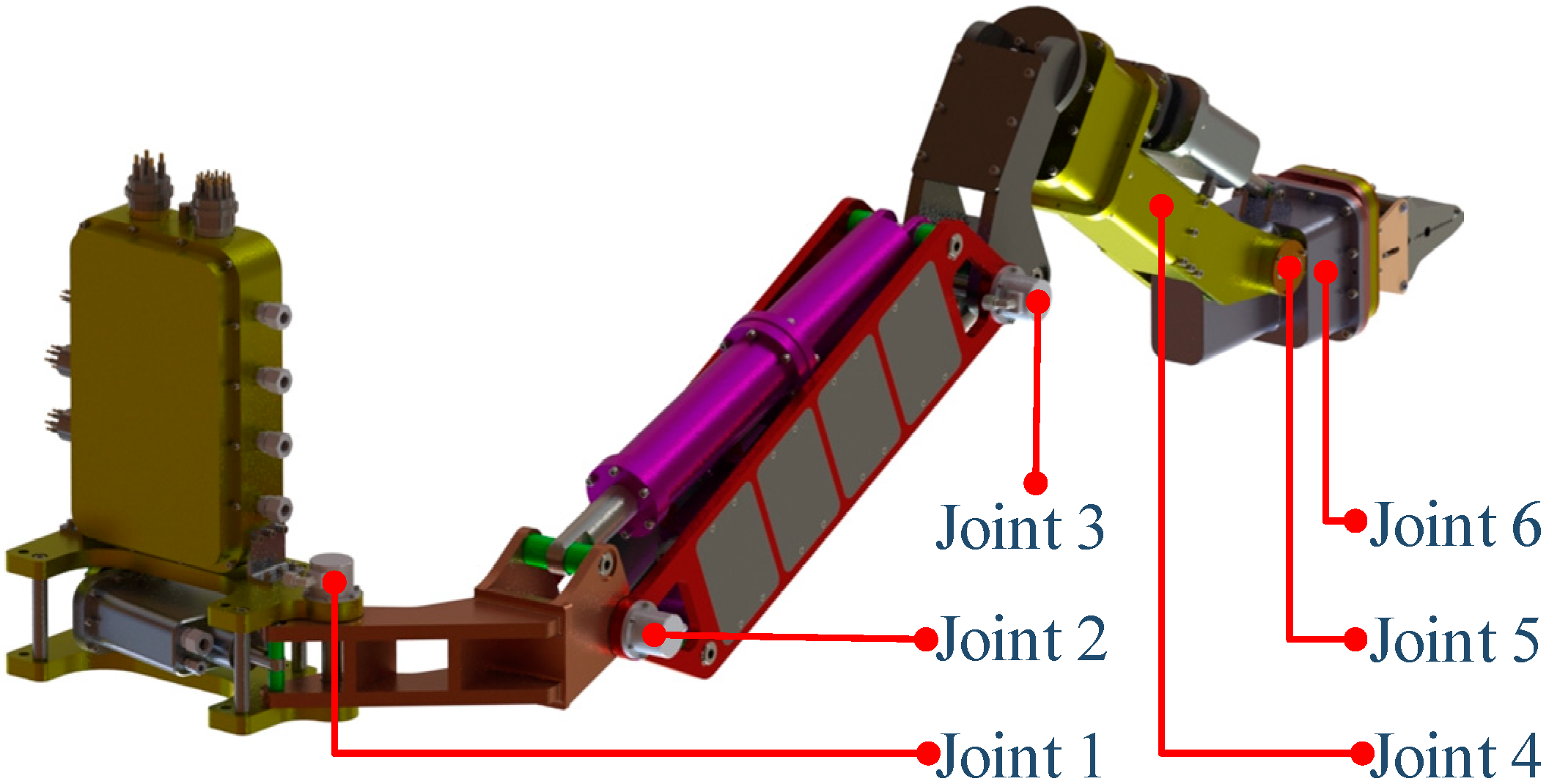
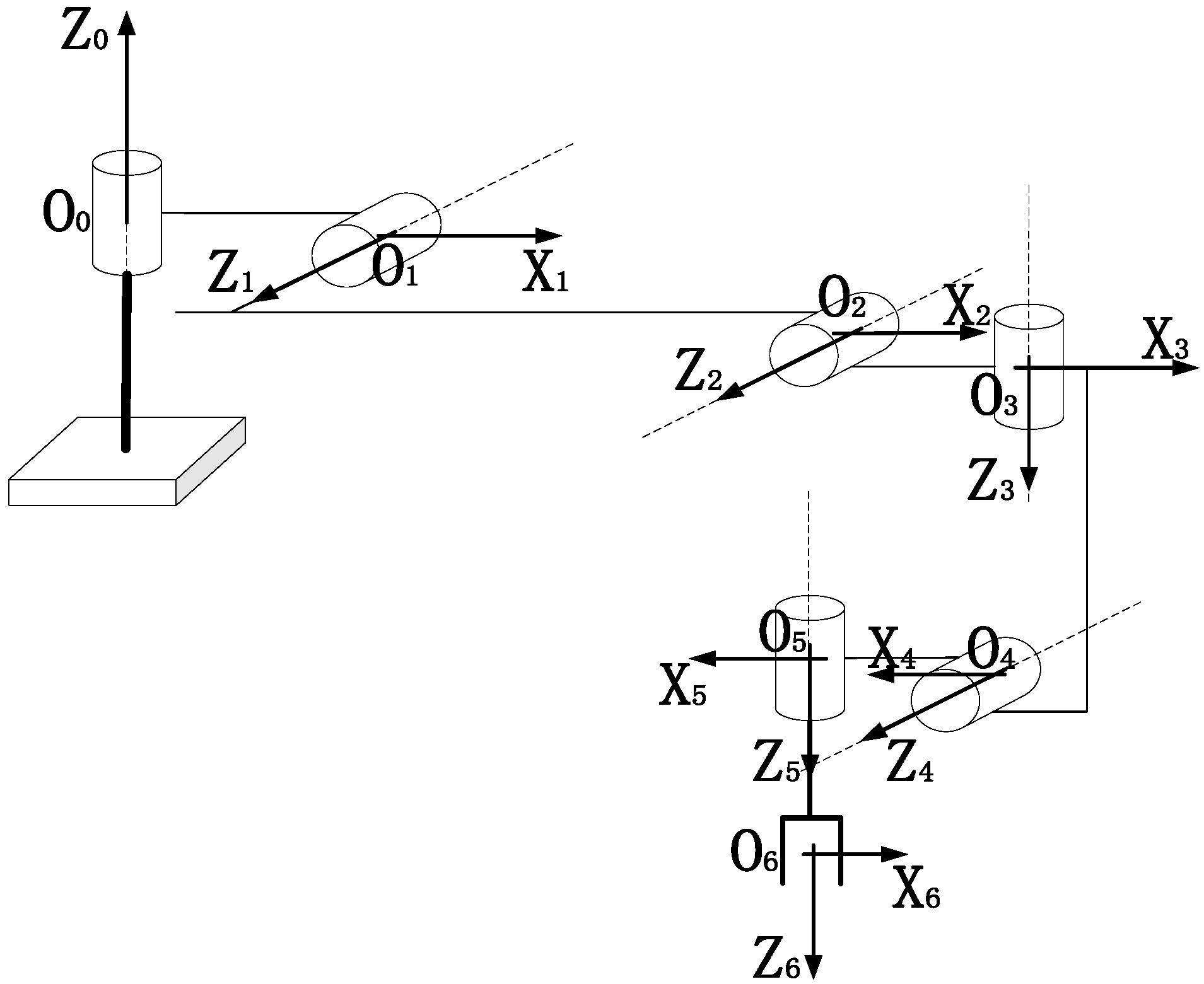
2.1. Kinematics Modelling of the Deep-Sea Manipulator

Figure 3 shows a three-dimensional model of the deep-sea electric manipulator, which has six degrees of rotation freedom and a clamp function. The weight of the manipulator is 65 kg, and the maximum load is 35 kg in the full extension state. The deep-sea manipulator is suitable for all ocean depths known to humankind at present, and it uses oil-filled compensation to resist immense water pressure.
Figure 4 shows the kinematic coordinate system of the deep-sea electric manipulator. Table 1 shows the kinematic parameters of the six joints of the manipulator. The kinematic model is established as
X e = A 1 0 ( q 1 ) A 2 1 ( q 2 ) A 3 2 ( q 3 ) A 4 3 ( q 4 ) A 5 4 ( q 5 ) A 6 5 ( q 6 )
where Xe represents the end-effector pose matrix, Aii−1 represents the coordinate transformation matrix of adjacent joints, and qi represents the joint angle position.

2.2. Dynamic Modelling of the Deep-Sea Manipulator

The dynamic model of the deep-sea electric manipulator based on the Lagrange method is established as [23]
M ( q ) q ¨ + N ( q , q ˙ ) q ˙ + f ( q ˙ ) + W ( q , q ˙ ) + g ( q ) + O ( q ) = τ
where M ( q ) represents the inertia matrix, N ( q , q ˙ ) represents the centrifugal force and the Coriolis force, f ( q ˙ ) represents the frictional force, W ( q , q ˙ ) represents the hydrodynamic force, g ( q ) represents gravity, O ( q ) represents buoyancy, and τ represents the joint driving torque. In the following sections, these variables are abbreviated.
The hydrodynamics of the deep-sea manipulator include mainly additional mass force and water resistance [24,25]. The additional mass force is related to the acceleration of the manipulator movement, and the water resistance is related to the speed of the manipulator movement [26,27]. At present, it is usually calculated by the empirical equation [28,29]
W = W R + W M = ρ W C R r 0 l v v d l + ρ W C M A 0 l v ˙ d l
where W R represents the water resistance, W M represents the additional mass force, ρ W represents the seawater density, C R represents the water resistance coefficient, l represents the arm length, r represents the arm radius, v represents the velocity relative to fluid, C M represents the additional mass force coefficient, and A represents the area facing fluid.
The deep-sea electric manipulator is filled with electric insulating oil to compensate for seawater pressure. However, high-speed rotation of the joint motor and reducer in the compensation oil leads to adverse viscous friction resistance. The low-temperature and high-pressure deep-sea environment results in an increase in the viscosity of the compensation oil, which leads to a prominent increase in the viscosity friction resistance. This resistance reduces the output efficiency and dynamic characteristics of the joint. Considering the influence of the viscous resistance, the joint driving torque τ in Equation (2) is further expressed as
τ = I η ( τ M τ V )
where I represents the reduction ratio vector, η represents the efficiency vector, τ M represents the motor output torque, and τ V represents the viscous resistance. The modelling method of the viscous resistance τ V has been studied and verified in previous work [30].
By substituting Equation (4) into (2), the complete dynamic model of the deep-sea electric manipulator is established as
M q ¨ + N q ˙ + f + W + g + O = I η ( τ M τ V )

3. Dynamic Dexterity Evaluation Method

3.1. Dynamic Manipulability

The dynamic model of a conventional manipulator is:
M q ¨ + N q ˙ + f + g = τ
Compared with Equation (5), the hydrodynamic force, viscous force, and buoyancy are excluded.
The linear mapping relationship between the end-effector velocity and joint angular velocity is expressed as
v = J q ˙
where J represents the manipulator Jacobian matrix. By differentiating Equation (7), the end-effector acceleration is obtained as
a = J q ¨ + J ˙ q ˙
Equation (8) is substituted into Equation (6) to obtain
a = J M 1 τ + J M 1 A
where A = M J 1 J ˙ q ˙ N q ˙ f g . It can be seen from Equation (9) that the end-effector acceleration a for a given configuration q is obtained by the superposition of the contributions of the joint torque τ and the additional torque A .
The joint driving torque is normalized as:
τ ˜ = T 1 τ
where T = diag [ τ 1 _ max , τ 2 _ max , τ 3 _ max , τ 4 _ max , τ 5 _ max , τ 6 _ max ] represents the normalized matrix, τ i _ max = I η τ i _ m o t . max represents the joint torque boundary, and τ i _ m o t . max represents the joint motor torque boundary. At this point, a Euclidean norm form can be obtained as
τ ˜ 1
The dynamic manipulability ε of a conventional manipulator [31] is defined as
ε { a = J M 1 T τ ˜ + J M 1 A τ ˜ 1 }
The dynamic manipulability ε represents the set of achievable end-effector accelerations that can be obtained when τ spans the set of all allowed joint torques.

3.2. Dynamic Torque Boundary

It can be seen from Equations (5) and (6) that the deep-sea manipulator is affected by additional hydrodynamic force, viscous force, and buoyancy. These factors reduce the effective joint torque and affect the normalized matrix in Equation (10). Considering the influence of these factors, the joint torque boundary of the deep-sea manipulator is modified as:
τ mod _ max = ( τ m o t _ max τ v ) I η W O
Considering the unique dynamic factors of the deep-sea manipulator, the modified joint torque boundary τ mod _ max changes dynamically with the joint motion state.
Substituting Equation (13) into Equation (12), the dynamic manipulability of the deep-sea manipulator is obtained:
ε d . s . { a = J M 1 T mod τ ˜ + J M 1 A τ ˜ 1 }
where T mod represents the modified normalized matrix.

3.3. Dynamic Dexterity with Jacobian Mapping Constraint

Because the deep-sea manipulator discussed in this paper is non-redundant, Equation (14) can be solved to give
τ ˜ = T mod 1 M J 1 a T mod 1 A
By substituting Equation (15) into Equation (11), the dynamic manipulability ellipsoid is established as
( a J M 1 A ) T J T M T mod 2 M J 1 ( a J M 1 A ) 1
Equation (16) represents the mapping relationship between the joint torque unit ball and end-effector acceleration ellipsoid. The positive definite ellipsoid core J T M T mod 2 M J 1 is determined by the kinematic and dynamic parameters of the deep-sea manipulator and uniquely determines the direction and length of the principal axis of the dynamic manipulability ellipsoid.
The dynamic manipulability of the deep-sea manipulator represents the mapping between the joint torque and end-effector acceleration without considering the limit of the joint velocity boundary. The motion speed of a deep-sea electric manipulator is generally lower than that of a conventional manipulator, so the joint angular velocity boundary is an important index affecting the end-effector dynamic.
In this paper, a dynamic evaluation method for the deep-sea electric manipulator with the Jacobian mapping constraint is proposed based on the dynamic manipulability, which is defined as dynamic dexterity. The basic principle of this method is to solve the constraint of joint velocity boundary on end-effector velocity by a Jacobian mapping relation and then synthesize the constraint and dynamic manipulability into a reachable space within a given time.
The velocity constraint of the end-effector along the principal axis of the dynamic manipulative ellipsoid is established as
v max = E 1 J q ˙ max
where E represents the matrix containing all the eigenvectors of the dynamic manipulative ellipsoid.
The maximum reachable space of the end-effector within a given time is calculated by using the limit of velocity and acceleration along all directions:
D i s max = { v max 2 2 a max + ( δ t v max a max ) v max , ( a max δ t > v max ) a max δ t 2 2 , ( a max δ t v max )
where Δ t represents the given time. The mapping relationship between the end-effector displacement and joint torque under the joint velocity boundary is defined as the dynamic dexterity to provide a more accurate and quantitative index to evaluate the deep-sea manipulator.

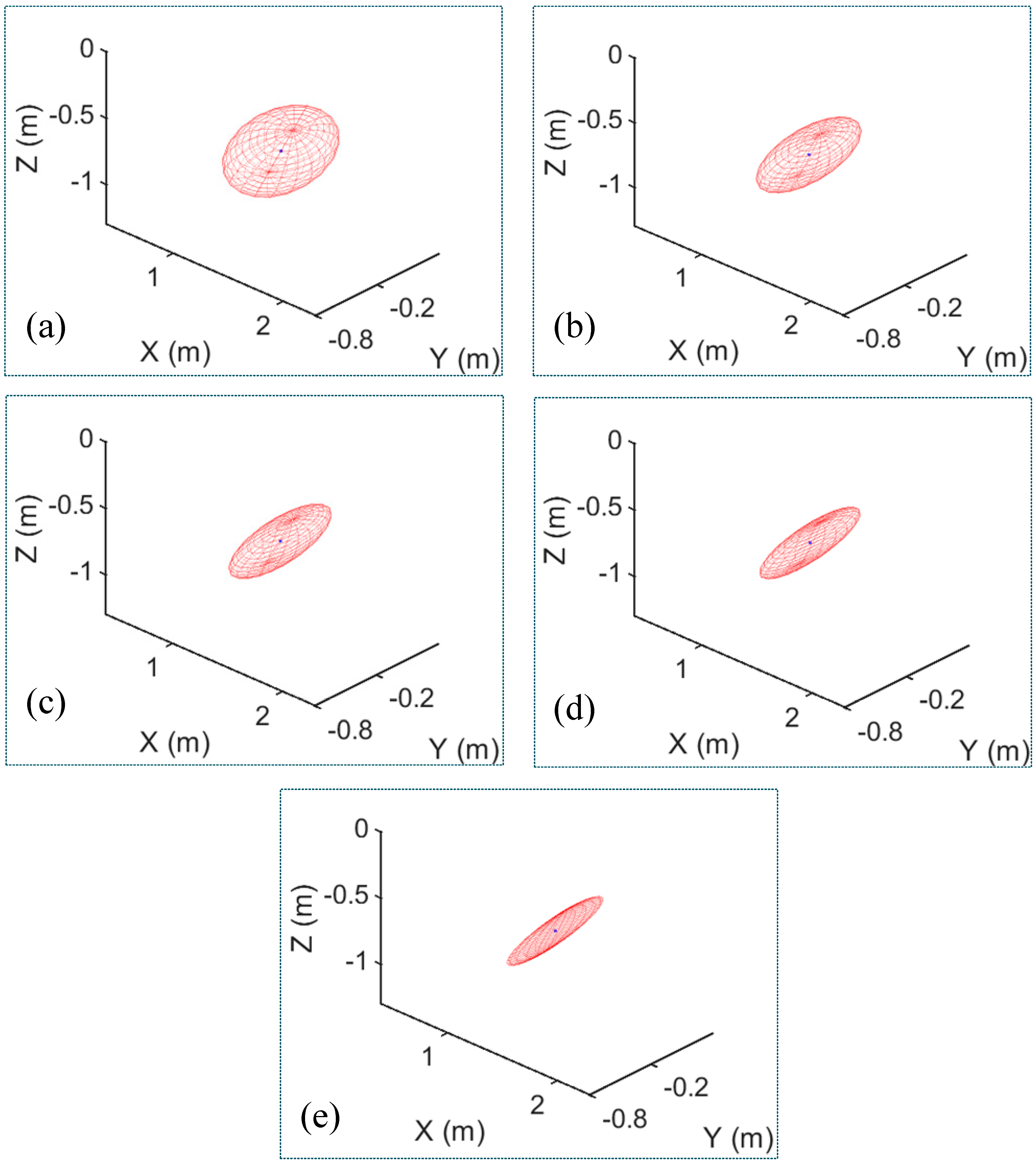
3.4. Dynamic Dexterity Ellipsoid and Dynamic Dexterity Measure

The relationship between the dynamic dexterity ellipsoid and depth is shown in Figure 5. The dynamic dexterity ellipsoid of the deep-sea manipulator in a typical operating posture is obtained based on Equation (18). The physical significance of the ellipsoid represents the maximum reachable space of the end-effector in finite time. This finite time is artificially specified and is set to 1 s in this paper. The dynamic dexterity ellipsoid represents the ultimate performance of the kinematics and dynamics of the deep-sea manipulator.
The dynamic dexterity measure is established as
I m e a n = 1 3 ( D i s max 1 + D i s max 2 + D i s max 3 )
The D i s max 1 , D i s max 2 , and D i s max 3 represent the length of the ellipsoidal principal axis. The I mean is positively correlated with the volume of the dynamic dexterity ellipsoid and represents the mean reachable distance of the end-effector in finite time (1 s). The relationship between dynamic dexterity measure and depth is shown in Table 2.

4. Viscous Resistance Optimization

As shown in Table 2 and Table 3, the dynamic dexterity of the deep-sea manipulator decreases with the increase in depth. This is because the greater the depth, the higher the viscosity of the compensating oil. The high viscosity compensation oil leads to greater viscosity resistance and reduces the dynamic performance of the manipulator.
Figure 6 shows the relation between the dynamic dexterity and the compensatory oil viscosity, and the dexterity is negatively correlated with the oil viscosity monotonically. The compensation oil with low viscosity and small viscosity–pressure coefficient is of great significance to ensure the dexterity of the deep-sea manipulator.
The viscosity resistance optimization is regarded as an analytical optimization problem focusing on engineering rather than a mathematical optimization problem. This paper studies the dynamic dexterity with three different viscosity oils as compensation oil. Table 3 shows the relationship between oil viscosity and depth (pressure), where the synthetic oil is a homemade mixture of kerosene and transformer oil. It can be seen from this table that the synthetic oil has significantly lower viscosity at all depths (pressures) and is most suitable for compensating oil.

5. Experiment

5.1. Experimental Method

Because an actual deep-sea experiment is very expensive, a pressure tank is used to simulate the deep-sea experiment environment. As shown in Figure 7, the deep-sea manipulator is placed in the pressure tank. The master manipulator controller is connected with the deep-sea manipulator through a watertight cable. The master manipulator controller can also record the motion data of the deep-sea manipulator in real time. The monitor shows the motion of the manipulator in the pressure tank.
In the process of the simulated deep-sea experiment, the pressure inside the pressure tank varies from 0 to 115 MPa, simulating the pressure environment from the surface to the deepest point of the ocean. The compensation oil of the deep-sea manipulator adopts 22# hydraulic oil, 10# hydraulic oil, and synthetic oil, respectively.
The physical meaning of the dexterity indicator is the reachable space of the end-effector in a limited time at the current pose. In the process of the simulated deep-sea experiment, the experimental data of dexterity are obtained by testing the average distance of the end-effector moving in multiple directions in a finite time (1 s). The experimental process is tested under the limit of the kinematic and dynamic practical performance of the deep-sea manipulator.

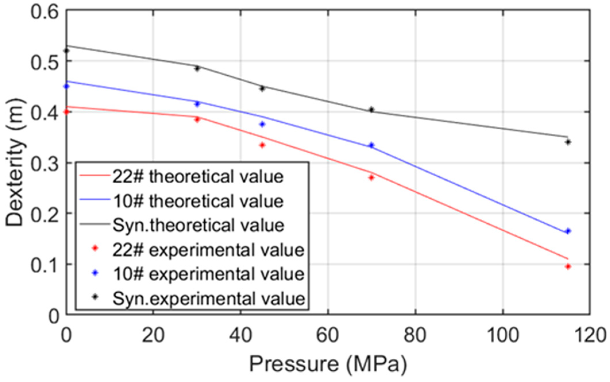
5.2. Experimental Results

The experimental results are shown in Figure 8. The figure shows the relationship between dexterity and pressure when three different compensation oils are used in the deep-sea manipulator. The theoretical value of the dynamic dexterity is calculated from Equation (19). The experimental value is tested and obtained according to the physical definition of dynamic dexterity. In the figure, discrete points represent experimental data, and continuous lines represent theoretical data.
It can be seen from Figure 8 that the deviation between the experimental value and the theoretical value is small. The root mean square error is 0.03 m, which indicates that the dynamic dexterity evaluation method proposed in this paper is accurate enough. By comparing the dexterity of different viscosity oils, it is shown that the oil viscosity has obvious influence on the dynamic dexterity of the deep-sea manipulator, and the self-made synthetic oil with lower viscosity has the least influence on the dexterity, which is the most suitable for the use of compensation oils.

6. Conclusions and Discussion

A viscous resistance optimization method based on dynamic dexterity of a deep-sea manipulator is proposed in this paper. The dynamic dexterity evaluation method considers the special kinematic and dynamic characteristics of the deep-sea manipulator. A simulated deep-sea experiment shows that the proposed dynamic dexterity evaluation method is accurate enough, and the viscosity resistance optimization method is effective. The method presented in this paper is universal and can be used to evaluate and improve the dexterity of other underwater manipulators.
More dexterous manipulators are urgently needed for complex deep-sea intervention tasks. Based on the method proposed in this paper, the dexterity optimization can be further applied to the mechanical design, control algorithm, and trajectory planning of deep-sea manipulators, and the dexterity operation ability of the deep-sea manipulators will be comprehensively improved. Furthermore, the proposed method can also be extended to the dexterity evaluation of underwater vehicle manipulator systems.

Author Contributions

Funding acquisition, Q.Z.; methodology, Y.B.; project administration, Q.Z.; supervision, A.Z.; writing—original draft, Y.B. All authors have read and agreed to the published version of the manuscript.

Funding

This work is supported by the Strategic Priority Research Program of the Chinese Academy of Sciences (Grant No. XDA22040102).

Institutional Review Board Statement

Not applicable.

Informed Consent Statement

Not applicable.

Data Availability Statement

Not applicable.

Acknowledgments

The valuable comments from the anonymous reviewers are highly appreciated.

Conflicts of Interest

The authors declare no conflict of interest.

References

  1. Stuart, H.; Wang, S.; Khatib, O.; Cutkosky, M.R. The Ocean One hands: An adaptive design for robust marine manipulation. Int. J. Robot. Res. 2017, 36, 150–166. [Google Scholar] [CrossRef]
  2. Ribas, D.; Ridao, P.; Turetta, A.; Melchiorri, C.; Palli, G.; Fernandez, J.J.; Sanz, P.J. I-AUV Mechatronics Integration for the TRIDENT FP7 Project. IEEE/ASME Trans. Mechatron. 2015, 20, 2583–2592. [Google Scholar] [CrossRef]
  3. Manley, J.E.; Halpin, S.; Radford, N.; Ondler, M. Aquanaut: A New Tool for Subsea Inspection and Intervention. In Proceedings of the OCEANS 2018 MTS/IEEE Charleston, Charleston, SC, USA, 22–25 October 2018; pp. 1–4. [Google Scholar] [CrossRef]
  4. Ding, N.; Tang, Y.; Jiang, Z.; Bai, Y.; Liang, S. Station-Keeping Control of Autonomous and Remotely-Operated Vehicles for Free Floating Manipulation. J. Mar. Sci. Eng. 2021, 9, 1305. [Google Scholar] [CrossRef]
  5. Sivčev, S.; Coleman, J.; Omerdic, E.; Dooly, G.; Toal, D. Underwater manipulators: A review. Ocean Eng. 2018, 163, 431–450. [Google Scholar] [CrossRef]
  6. Fan, Y.; Zhang, Q.; Wang, H.; Bai, Y.; Zhang, Y.; Cui, S. Design and Experiments of a 11000m 7-Function Electric Manipulator System. In Proceedings of the OCEANS-MTS/IEEE Kobe Techno-Oceans (OTO), Kobe, Japan, 28–31 May 2018; pp. 1–4. [Google Scholar] [CrossRef]
  7. Yunfei, B.; Qifeng, Z.; Yunlong, F.; Xinbao, Z.; Qiyan, T.; Yuangui, T.; Aiqun, Z. Trajectory planning of deep-sea electric manipulator based on energy optimization. Robot 2020, 42, 301–308. [Google Scholar]
  8. Bai, Y.; Zhang, Q.; Tian, Q.; Yan, S.; Tang, Y.; Zhang, A. Performance and experiment of deep-sea master-slave servo electric manipulator. In Proceedings of the CEANS 2019 MTS/IEEE, Seattle, WA, USA, 27–31 October 2019; pp. 1–5. [Google Scholar] [CrossRef]
  9. Hwang, S.; Kim, H.; Choi, Y.; Shin, K.; Han, C. Design optimization method for 7 DOF robot manipulator using performance indices. Int. J. Precis. Eng. Manuf. 2017, 18, 293–299. [Google Scholar] [CrossRef]
  10. Nabavi, S.N.; Akbarzadeh, A.; Enferadi, J.; Kardan, I. A homogeneous payload specific performance index for robot manipulators based on the kinetic energy. Mech. Mach. Theory 2018, 130, 330–345. [Google Scholar] [CrossRef]
  11. Wang, N.; Zhang, Z.; Zhang, X. International Conference on Intelligent Robotics and Applications; Springer: Cham, Switzerland, 2017; pp. 554–563. [Google Scholar] [CrossRef]
  12. Sotiropoulos, P.; Aspragathos, N. Neural networks to determine task oriented dexterity indices for an underwater vehicle-manipulator system. Appl. Soft Comput. 2016, 49, 352–364. [Google Scholar] [CrossRef]
  13. Albiez, J.; Hildebrandt, M.; Kerdels, J.; Kirchner, F. Automatic workspace analysis and vehicle adaptation for hydraulic underwater manipulators. In Proceedings of the OCEANS 2009, Biloxi, MS, USA, 26–29 October 2009; pp. 1–6. [Google Scholar] [CrossRef]
  14. Asokan, T.; Seet, G.; Lau, M.; Low, E. Optimum positioning of an underwater intervention robot to maximise workspace manipulability. Mechatronics 2005, 15, 747–766. [Google Scholar] [CrossRef]
  15. Patel, S.; Sobh, T. Manipulator Performance Measures - A Comprehensive Literature Survey. J. Intell. Robot. Syst. 2015, 77, 547–570. [Google Scholar] [CrossRef] [Green Version]
  16. Xu, R.; Luo, J.; Wang, M. Kinematic and dynamic manipulability analysis for free-floating space robots with closed chain constraints. Robot. Auton. Syst. 2020, 130, 103548. [Google Scholar] [CrossRef]
  17. Li, Y.; Jiao, Z.; Yu, T.; Shang, Y. Viscous Loss Analysis of the Flooded Electro-Hydrostatic Actuator Motor under Laminar and Turbulent Flow States. Processes 2020, 8, 975. [Google Scholar] [CrossRef]
  18. Pirrò, D.; Quadrio, M. Direct numerical simulation of turbulent Taylor–Couette flow. Eur. J. Mech. B/Fluids 2008, 27, 552–566. [Google Scholar] [CrossRef] [Green Version]
  19. Bai, Y.; Zhang, Q.; Fan, Y.; Wang, H.; Zhang, A. Research and Experiment on Viscous Friction Power Loss of Deep-Sea Electric Manipulator. In Proceedings of the OCEANS-MTS/IEEE Kobe Techno-Oceans (OTO), Kobe, Japan, 28–31 May 2018; pp. 1–4. [Google Scholar] [CrossRef]
  20. Cai, M.; Wu, S.; Yang, C. Effect of Low Temperature and High Pressure on Deep-Sea Oil-Filled Brushless DC Motors. Mar. Technol. Soc. J. 2016, 50, 83–93. [Google Scholar] [CrossRef]
  21. Deng, D. A Numerical and Experimental Investigation of Taylor Flow Instabilities in Narrow Gaps and Their Relationship to Turbulent Flow in Bearings. Ph.D. Thesis, Akron University, Ahron, OH, USA, 2007. [Google Scholar]
  22. Wenjuan, Q.; Jibin, Z.; Jianjun, L. Numerical calculation of viscous drag loss of oil-filled BLDC motor for underwater applications. In Proceedings of the 2010 International Conference on Electrical Machines and Systems, Incheon, Korea, 10–13 October 2010; pp. 1739–1742. [Google Scholar]
  23. Yuguang, Z.; Fan, Y. Dynamic modeling and adaptive fuzzy sliding mode control for multi-link underwater manipulators. Ocean Eng. 2019, 187, 106202. [Google Scholar] [CrossRef]
  24. Kołodziejczyk, W. Preliminary Study of Hydrodynamic Load on an Underwater Robotic Manipulator. J. Autom. Mob. Robot. Intell. Syst. 2015, 9, 11–17. [Google Scholar] [CrossRef]
  25. Kołodziejczyk, W. The method of determination of transient hydrodynamic coefficients for a single DOF underwater manipulator. Ocean Eng. 2018, 153, 122–131. [Google Scholar] [CrossRef]
  26. Takagi, H.; Nakashima, M.; Ozaki, T.; Matsuuchi, K. Unsteady hydrodynamic forces acting on a robotic arm and its flow field: Application to the crawl stroke. J. Biomech. 2014, 47, 1401–1408. [Google Scholar] [CrossRef]
  27. Filaretov, V.; Konoplin, A. Experimental definition of the viscous friction coefficients for moving links of multilink underwater manipulator. In Proceedings of the 26th DAAAM International Symposium on Intelligent Manufacturing and Automation, Zadar, Croatia, 21–24 October 2015; pp. 0762–0767. [Google Scholar] [CrossRef]
  28. McMillan, S.; Orin, D.; McGhee, R. Efficient dynamic simulation of an underwater vehicle with a robotic manipulator. IEEE Trans. Syst. Man Cybern. 1995, 25, 1194–1206. [Google Scholar] [CrossRef] [Green Version]
  29. McLain, T.; Rock, S. Experiments in the hydrodynamic modeling of an underwater manipulator. In Proceedings of the Symposium on Autonomous Underwater Vehicle Technology, Monterey, CA, USA, 2–6 June 1996; pp. 463–469. [Google Scholar] [CrossRef]
  30. Bai, Y.; Zhang, Q.; Zhang, A. Modeling and Optimization of Compensating Oil Viscous Power for a Deep-Sea Electric Manipulator. IEEE Access 2021, 9, 13524–13531. [Google Scholar] [CrossRef]
  31. Chiacchio, P. A new dynamic manipulability ellipsoid for redundant manipulators. Robotica 2000, 18, 381–387. [Google Scholar] [CrossRef]
Figure 1. Haidou I underwater robot. (by Shenyang Institute of Automation).
Jmse 10 00876 g001
Figure 2. Deep-sea 6 d.o.f. electric manipulator.
Jmse 10 00876 g002
Figure 3. Joint numbers of the deep-sea electric manipulator.
Jmse 10 00876 g003
Figure 4. Kinematic coordinate system of the deep-sea manipulator.
Jmse 10 00876 g004
Figure 5. Relationship between dynamic dexterity ellipsoid and depth. (a) Depth: 1 m, compensating oil: No. (b) Depth: 1 m, compensating oil: Yes. (c) Depth: 4500 m, compensating oil: Yes. (d) Depth: 7000 m, compensating oil: Yes. (e) Depth: 11,000 m, compensating oil: Yes.
Jmse 10 00876 g005
Figure 6. Relationship between dexterity and oil viscosity.
Jmse 10 00876 g006
Figure 7. Simulated deep-sea experiment.
Jmse 10 00876 g007
Figure 8. Experimental results of the dynamic dexterity.
Jmse 10 00876 g008
Table 1. Kinematic parameters of the deep-sea manipulator.
Jointsq.(deg)d.(mm)α.(deg)a.(mm)
1−30~90090130.4
2−30~90138.20641.8
3−90~30090220.2
4−90~90442.6−9021.5
50~90090−48.1
6−180~180239.600
Table 2. Relationship between dynamic dexterity measure and depth.
DepthCompensating OilDynamic Dexterity Measure
1 mNo0.52 m
1 mYes0.48 m
4500 mYes0.40 m
7000 mYes0.27 m
11,000 mYes0.11 m
Table 3. Relationship between oil viscosity and depth (pressure).
22# Hydraulic Oil10# Hydraulic OilSynthetic Oil
0 m (0 MPa)157 cSt50 cSt4 cSt
4500 m (45 MPa)496 cSt94 cSt7 cSt
7000 m (70 MPa)857 cSt135 cSt11 cSt
11,000 m (110 MPa)2250 cSt270 cSt20 cSt
Publisher’s Note: MDPI stays neutral with regard to jurisdictional claims in published maps and institutional affiliations.

