1. Introduction
Suppression of vortex shedding in the wake of circular cylinders is of engineering importance because vortex-induced vibration (VIV) is a hazard for many engineering structures such as chimneys, offshore pipelines, power cables, heat exchanger tubes, etc. Many flow control methods for suppressing vortex shedding have been proposed, and they can be classified into two categories: active control and passive control. In active control, external energy is used to modify the boundary layers on the cylinder surface. Examples of active control include suction-based control [
1], jet control [
2,
3], and controlled cylinder rotation [
4]. Passive control involves controlling the flow by attaching small objects to the cylinder [
5,
6,
7] or by modifying the geometry of the cylinder [
8,
9,
10].
Proper placing of single or multiple control rods near a cylinder is believed to enable effective suppression of vortex shedding [
11,
12,
13]. One flow control target is drag reduction. Firat et al. [
7] conducted numerical simulations of flow past a square prism with an upstream control rod at
d/
D = 4 and Re = 200, where
D is the side length of a square prism (also called a square cylinder) or the diameter of a cylinder,
d is the diameter of the control rod, and the Reynolds number is defined based on
D. It was found that positioning a control rod at 2
D or 3
D upstream of the square prism can reduce the drag by 74% and the lift by up to 60%. Igarashi [
14] conducted an experimental study of flow control by placing a control rod upstream of a square prism with various rod diameters and rod-to-prism spacings and derived an empirical formula to estimate the critical gap below which the vortex shedding from the control rod disappears. Yen and Wu [
15] conducted an experimental study of a control rod upstream of a square cylinder and classified the vortex streets into single, attached, and bi-vortex streets by varying the Reynolds number and spacing ratio.
Placing a control rod in the wake of a cylinder can reduce the lift by interfering with the vortex dynamics. Gim, Kim et al. [
16] conducted experiments on flow control in the wake of a circular cylinder by placing a control rod at the rearward stagnation point, using the particle image velocimetry (PIV) technique for various rod diameters, and found that
d/
D = 0.3 has an excellent effect on reducing turbulence intensity. Chauhan, Dutta et al. [
17] conducted an experimental study of flow control using two small control rods in the shear layers behind a square cylinder, with
d/
D = 0.2 and Re = 485, and achieved a maximum 22% drag reduction. Lu, Liu et al. [
18] and Silva-Ortega and Assi [
19] conducted numerical and experimental investigations of flow control using multiple control rods surrounding a circular cylinder. Silva-Ortega and Assi [
19] found that the configuration of four control rods with a gap ratio of
G/
D = 0.05 (
G is the gap between the control rod and the main cylinder) and a diameter ratio of
d/
D = 0.06 produced the lowest drag, compared to all other configurations. Lu, Liu et al. [
18] classified the interference between the cylinder and rods into four flow regimes with varying suppression effectiveness and flow characteristics. Silva-Ortega and Assi [
20] investigated the suppression of VIV using multiple rotating control rods.
Using rotating control rods was found to have great potential to further improve the effectiveness of flow control. Mittal [
21] conducted two-dimensional numerical simulations of flow control using two small rotating rods on either side of the cylinder, with Re = 100 and 10
4, and found a significant reduction in the overall drag and lift forces. However, the power required to rotate the cylinder at Re = 100 was much higher than that at Re = 10
4. Using numerical simulations of flow control using twin control rods symmetrically placed behind a circular cylinder at
d/
D = 0.2 and Re = 150, Goodarzi and Dehkordi [
22] and Goodarzi and Dehkordi [
23] found the most effective positions for the rotating controllers for perfect suppression of vortex shedding. They reported that the most effective positions may vary for different engineering applications, and the presence of the rotating controllers usually resulted in the separation bubbles remaining attached to the system of cylinders. Schulmeister, Dahl et al. [
12] conducted a similar study of flow control using two control rods behind the cylinder but with a smaller rod-to-cylinder distance. They found a recirculation region around the control rod. The streamline reattached to the main cylinder with greater pressure than at separation, resulting in increased base pressure and reduced pressure drag. Placing two control rods in the wake of a cylinder was also found to be effective for the suppression of VIV [
24,
25]. Oscillatory rotation of the circular cylinder itself at the proper frequency and velocity also has the potential to weaken vortex shedding and reduce lift [
4,
26].
The majority of the above-mentioned studies of flow control methods using control rods focus on wake control, with control rods placed in the wake of the cylinder to control the formation of wake vortices. It is expected that the mechanisms of flow control will be different when the rod is placed in different locations around the cylinder. In this study, the mechanisms of flow control using a small control rod at various angular positions along the cylinder surface were investigated by conducting numerical simulations. Specifically, the control effect of the rod on the fluid force was examined through its interference with formation of the shear layer when the rod is upstream of the cylinder and with the formation of the vortices when it is downstream of the cylinder. Extensive simulations with a variety of position angles of the control rod relative to the cylinder were conducted, and the reduction or increase in the coefficients of fluid force on the cylinder were quantified.
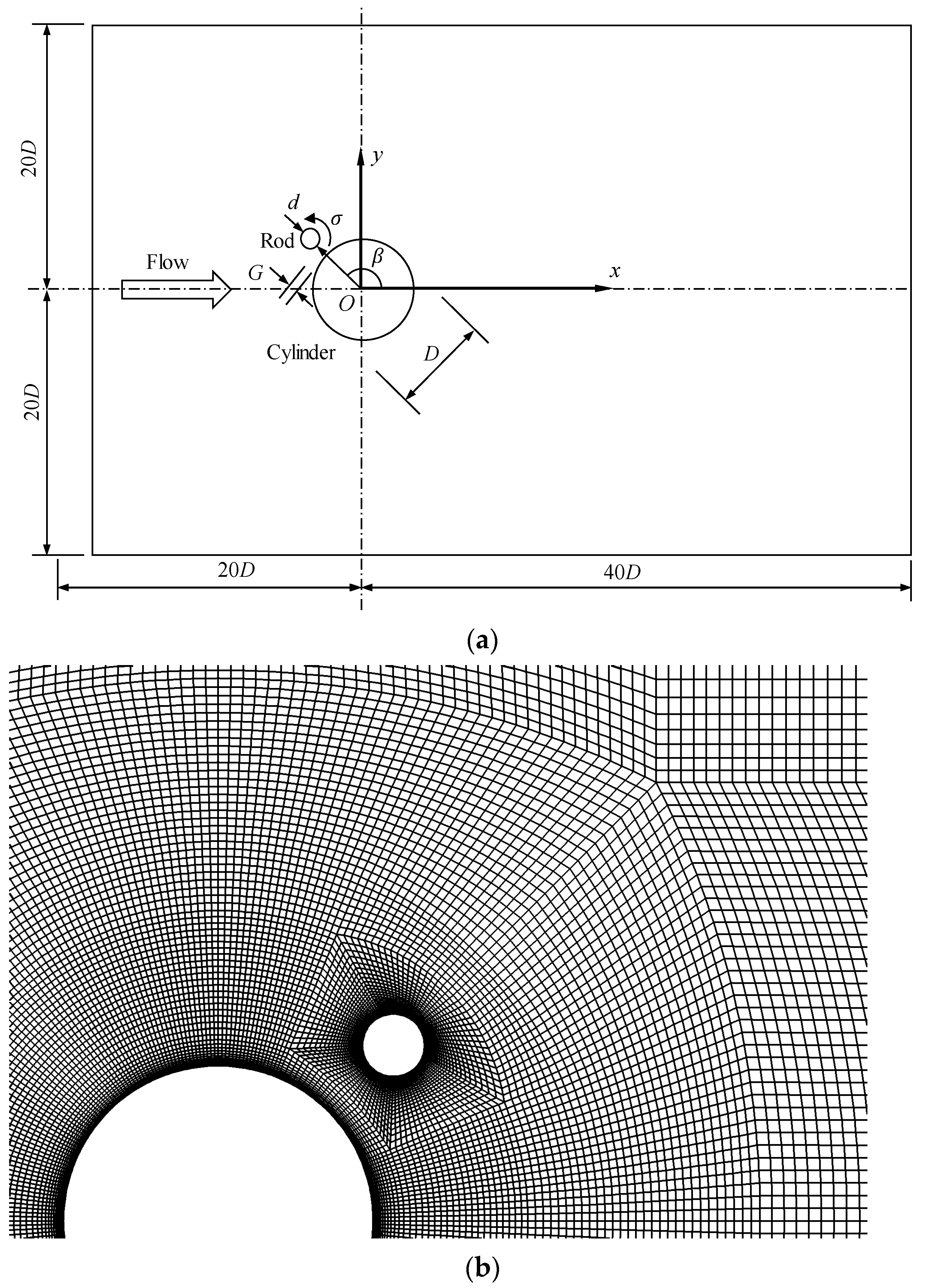
Figure 1a shows the use of a small rod (referred to as the rod hereafter) to control the flow around a cylinder with a diameter
D. The rod has a diameter
d, and its position relative to the cylinder is determined by a gap
G and a position angle
β. The angular rotational velocity is denoted by 𝜎, which is positive in the anticlockwise direction. The nondimensional rotational speed is defined as
, where
U is the free-stream velocity. This is referred to as the rotation rate hereafter. A Cartesian coordinate system
Oxy is defined, with its origin located at the center of the cylinder and with the
x-direction following the flow direction, as shown in
Figure 1.
In all the numerical simulations, the Reynolds number, the diameter ratio, and the gap ratio were Re = 200,
d/
D = 0.2, and
G/
D = 0.2, respectively. The Reynolds number is defined as Re =
UD/
ν, where
U and
ν are the fluid velocity and kinematic viscosity of the fluid, respectively. Vortex shedding occurred as Re exceeded 40, and was two-dimensional until the Reynolds number exceeded a critical value. The critical Re for transitioning from two-dimensional to three-dimensional flow varied between 140 to 194, depending on the disturbance in the flow in the experiments [
27]. The three-dimensional numerical study by Zhao, Thapa et al. [
28] indicated that the flow was in the two-dimensional flow regime up to Re = 200, and the lift coefficient of the cylinder increased with an increase in Re. In this paper, a Reynolds number of 200 was studied, because this Reynolds number is the highest Reynolds number with the largest lift coefficient in the two-dimensional regime. The focus of the study was to investigate the effects of the position angle
β and the rotation rate on the wake flow and lift coefficient. To achieve this, simulations were conducted for
β = 0°, 45°, 90°, 135°, and 180°, with rotation rates (
α) ranging from −7 to 7 and an interval of 0.2.
2. Numerical Method
The fluid was assumed to be an incompressible Newtonian fluid. The velocity, the time, and the pressure were nondimensionalized as
,
, and pressure
, where
u and
v are the fluid velocity components in the
x- and
y-directions, respectively,
is the fluid velocity, and
p is the pressure. In this paper, a wave dash ‘~’ on top of a variable represents a dimensional value. The nondimensional and two-dimensional Navier–Stokes (NS) equations are:
The NS equations were solved by the finite element method (FEM) and the corresponding in-house software developed by Zhao, Cheng et al. [
29]. The detailed FEM formulae can be found in Zhao, Cheng et al. [
29] and will not be presented here. A rectangular computational domain with a length of 60
D and a width of 40
D was used, and the cylinder was located 20
D downstream of the left boundary. Behr, Hastreiter et al. [
30] reported that the blockage ratio, i.e., the ratio of the cylinder diameter to the width of the computational domain, must be less than 0.0625, to ensure there is no blockage effect from the two lateral boundaries. The blockage effect in this paper was considered to be negligible, because the largest blockage ratio at
β = 90° was 0.03, which is less than half of the value recommended by Behr, Hastreiter et al. [
30].
The boundary conditions for solving the equations were specified as follows. On the inlet boundary, the velocity was given and the pressure gradient in the
x-direction was zero. On the outlet (right) boundary, the pressure was zero and the gradient of the velocity in the
x-direction was zero [
31,
32]. On the top and bottom boundaries, free-slip boundaries were used, i.e., the velocity in the
y-direction was zero and the gradients in the
y-direction of the pressure and the
x-velocity were zero. The fluid velocity was zero on the cylinder surface and the same as the rod’s rotation velocity on the rod’s surface. The gradient of the pressure normal to the wall surface was zero.
Figure 1b shows the computational mesh near the cylinder and rod for
β = 45°. The whole computational domain was divided into 47,468 structured quadrilateral 4-node linear finite elements. The surfaces of the cylinder and rod were divided into 288 and 136 finite elements, respectively, and the minimum nondimensional element size in the radial direction on the wall surfaces was 0.002.
3. Numerical Validation and Mesh Dependency Study
The nondimensional computational time was Δ
t = 0.00025. Zhao [
33] and Zhao, Cheng et al. [
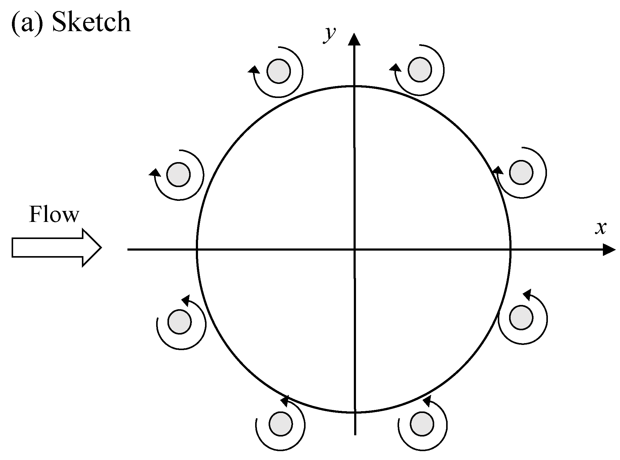
34] performed a detailed validation of the numerical model for flow past one and two cylinders at Re = 200 and flow past a rotating cylinder at Re = 200, respectively. Data for one cylinder with one control rod are not available for validation. However, we validated our model using the numerical results for the flow past eight control rods presented by Assi, Orselli et al. [
35]. The additional numerical simulations of the flow past a circular cylinder with eight control rods shown in
Figure 2a were conducted for the purpose of validation. The diameter ratio, the Reynolds number, and the gap ratio were
d/
D = 0.05, Re = 100, and
G/
D = 0.05, respectively. The eight control rods rotated at the same rate, but the top four rods rotated in the clockwise direction and the bottom four rods rotated in the anticlockwise direction. The coefficients of drag and lift on the cylinder were defined as
and
, where
FDC and
FLC are the drag and lift forces of the cylinder, respectively. The coefficients of drag and lift on the rod were defined as
and
, where
FDR and
FLR are the drag and lift forces on the rod, respectively. An overbar and a prime on a force coefficient denote the mean value and the standard deviation (SD) of the force coefficient, respectively. For example,
and
denote the mean drag and lift coefficients on the cylinders, and
and
denote the standard deviations of the drag and lift coefficients on the cylinder, respectively.
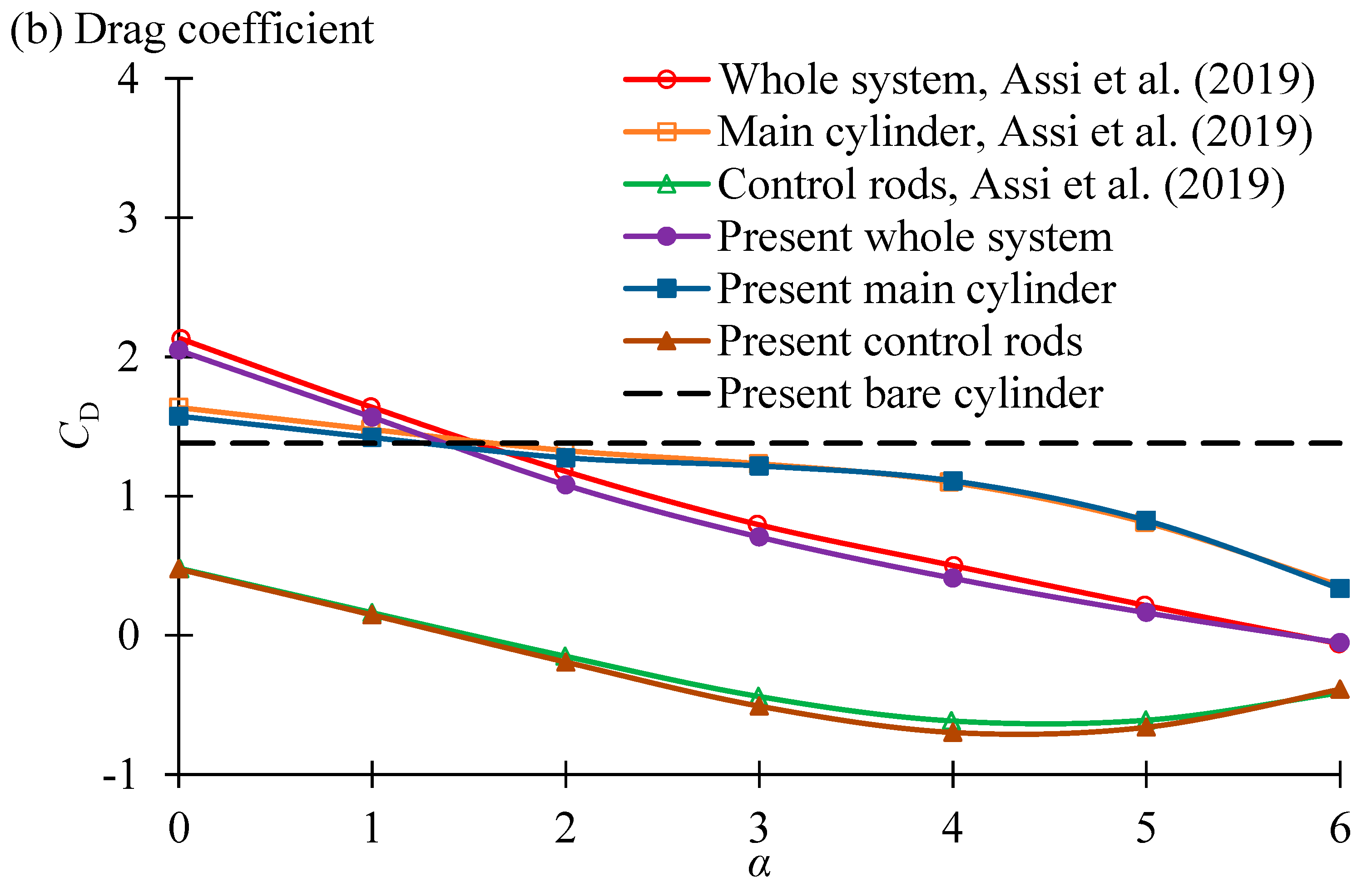
Figure 2 shows the mean drag coefficient as a function of the rotation rate in comparison with the numerical results in [
35]. The drag coefficient on the control rods is the sum of the drag coefficients of all the eight rods in the figure. The mean drag coefficient of the whole system is greater than that of a bare cylinder at
α = 0 and 1. With an increase in
α, the mean drag coefficient continuously decreases, becoming slightly smaller than zero at
α = 6. The variation trend presented in the numerical results agrees with that in [
35], with only a very small difference. We further reduced the mesh density but did not obtain results that were closer to those of [
35]. The relative error between the two sets of results was defined as
. In the whole range of
the maximum values of
of the drag coefficients of the whole system, the main cylinder, and the rods were 0.073, 0.045, and 0.060, respectively.
To ensure the density of the mesh was sufficiently small to obtain a converged solution, a mesh dependency study was conducted by performing simulations for
β = 90° and the largest rotation rate of
α = 7, using three additional meshes, and the results for the force coefficients are listed in
Table 1. The density of each mesh is characterized by the total finite element number
Nelement, the element number along the cylinder
Ne,cylinder, the element number along the rod
Ne,rod, and the mesh size in the radial direction on the cylinder and rod Δ
r1. The normal mesh is the one used for all the simulations in this study.
It can be seen from
Table 1 that the force coefficients from the dense and the normal meshes were very close to one another. The differences in
,
, and
for the dense and normal meshes were 0.78%, 1.05%, 0.33%, and 0.47, respectively. The results from the coarse and dense meshes also showed little difference from one another. To prove that Δ
t = 0.00025 was sufficiently small for obtaining accurate results, the effects of the nondimensional computational time step Δ
t on the results were also studied, by conducting simulations at
β = 90° and
α = 7 using normal mesh under three different computational time steps of Δ
t = 0.00025, 0.0005, and 0.001. As seen in
Table 2, the differences in
,
,
, and
for Δ
t = 0.00025 and 0.0005 were 0.41%, 0.53%, 0.33%, and 0.07, respectively.
4. Results
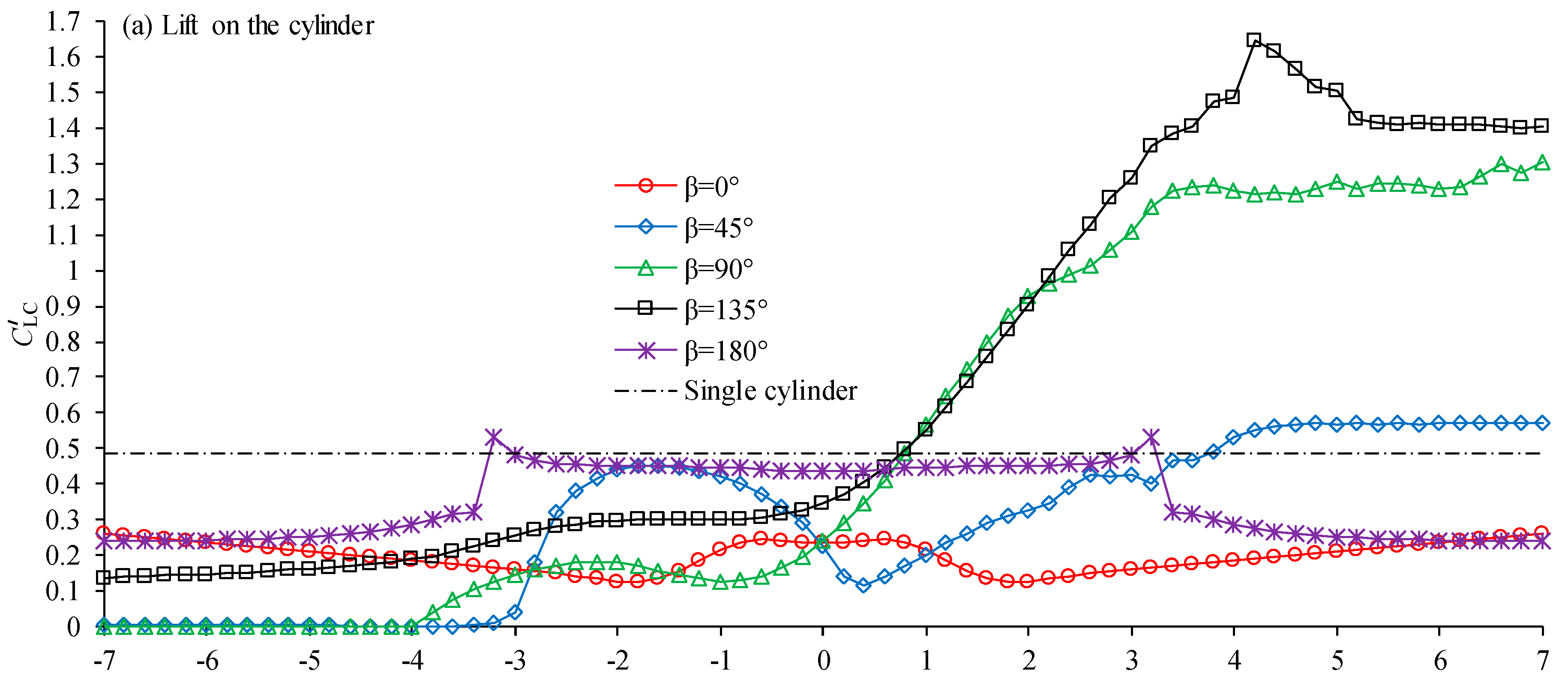
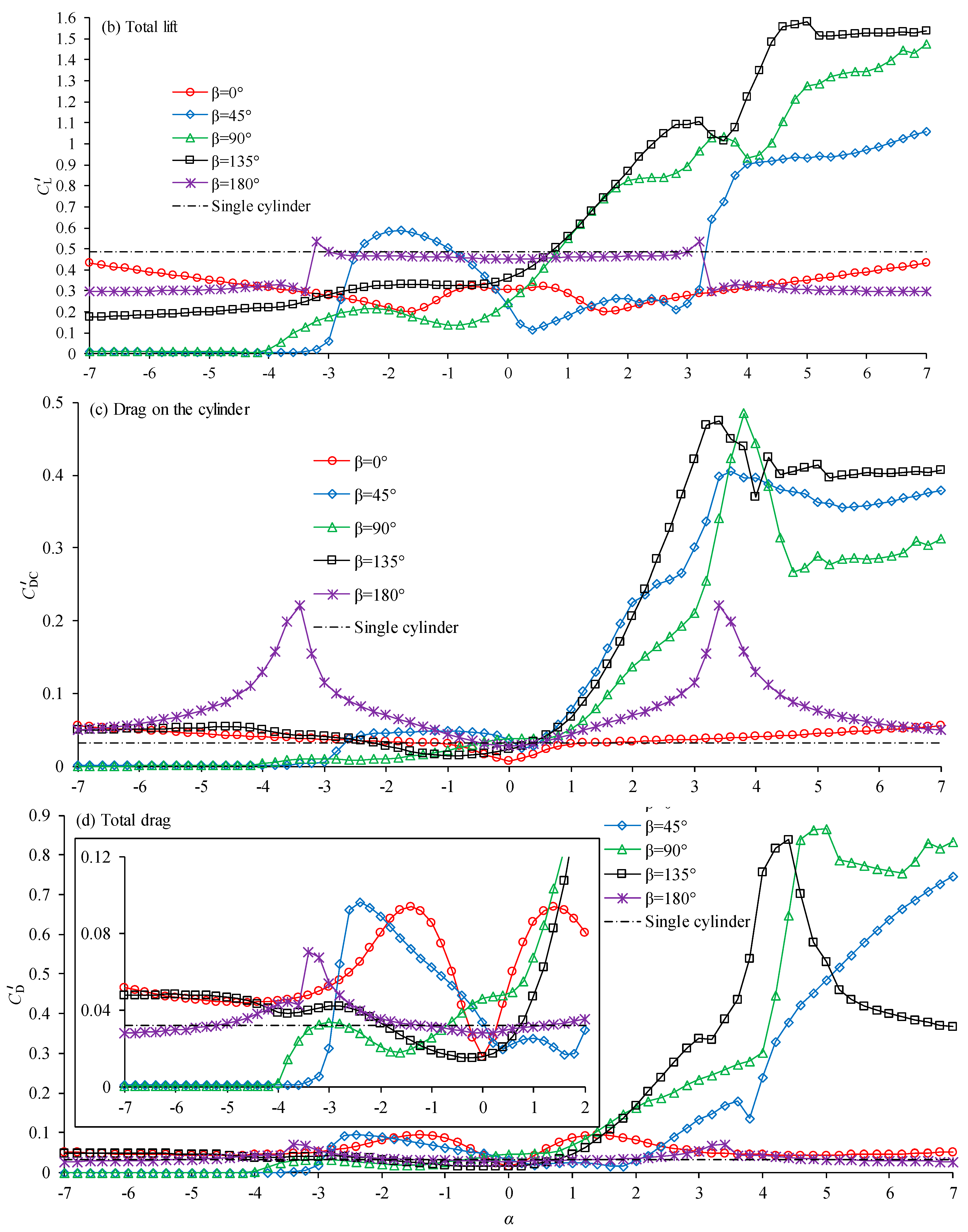
Figure 3 shows the variation in the standard deviations (SD) of the lift and drag coefficients with rotation rate. The total drag and total lift coefficients were defined as
and
, respectively. The mean and SD of the force coefficients were obtained using the data within 10 vortex shedding periods. The variation in the SD of the lift coefficient of the cylinder was very similar to that of the total lift coefficient for all the position angles of the rod, except that the SD of the total lift coefficient was slightly greater than the SD of the lift coefficient of the cylinder. The best reduction in the SD of the lift coefficient occurred for
, for all the position angles of the rod.
To give a clear view of the very small SD of the drag coefficients for all the negative rotation rates, a view with a small vertical axis scale is presented in
Figure 3d. It can be seen that
, in the range of
, was increased by around 50% to 100% for
β = 0°, 135°, and 180°. However, the increase in the SD of the drag coefficient was minimal, since it was insignificantly smaller than the SD of the lift coefficient. The SD of the drag on the cylinder (
) was increased significantly for
, but the SD of the total drag (
) was not, because the drag coefficients on the cylinder and rod were out of phase with each other.
The SD of both the drag and lift coefficients were increased dramatically when the rotation rate was positive with a high magnitude. Positive rotation rates have not been considered in many studies of flow control using rotating rods [
12,
22]. If vortex-induced vibration is utilized for energy harvesting, using a positive rotation of the rod would increase the energy significantly [
36].
When a uniform flow approaches the cylinder, shear layers generated on the cylinder surface form vortex shedding, which causes oscillation of the fluid force on the cylinder. To explain the effects of the control rod on the drag and lift coefficient, the flow was visualized using the contours of vorticities and streamlines. The nondimensional vorticity is defined as
. In the following discussion, shear layers whose vorticities are positive and negative are referred to as positive and negative shear layers, respectively. At
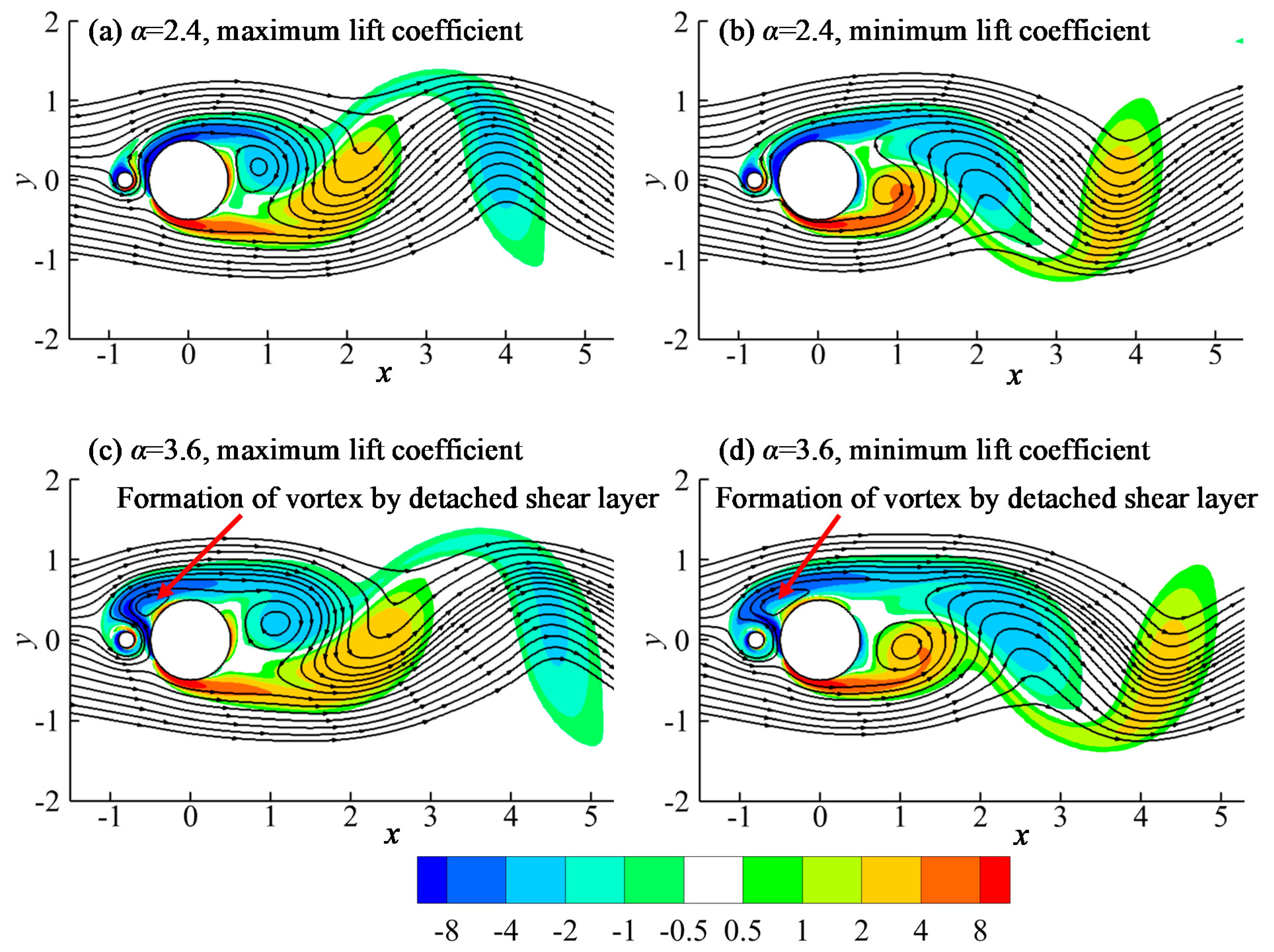
β = 180°, the SD of the drag and lift coefficients reduced suddenly as the rotation rate
α increased from 3.2 to 3.4, as shown in
Figure 3. The instantaneous flows at
α = 2.4 and 3.6 shown in
Figure 4 explain the sudden reduction. In
Figure 3a,b, where
α = 2.4, the rotating control rod did not have a significant effect on the shear layer formed on the cylinder surface, and the vortex shedding from the cylinder resembled that of a cylinder without control rods. The SD of the lift coefficient of the cylinder in
Figure 3a was close to that of a single cylinder at
α = 2.4. In
Figure 3c,d, where the total lift coefficient of both cylinders reached its maximum and minimum values, respectively, the rotation rate of the control rod was so large that it caused the negative shear layer to separate from the top side surface of the cylinder, forming a vortex and finally reattaching to the cylinder surface again behind the vortex, as indicated in
Figure 3c,d. The separation and reattachment of the shear layer on the top surface of the cylinder weakened the vortex shedding, and the lift coefficient was weakened significantly.
To further understand the effects of the rotating rod on the flow and the force coefficients, the streamlines and the contours of the vorticity based on the mean flow are discussed, and the correlation between the flow and force coefficients analyzed. The mean flow is the averaged flow over one vortex shedding period. Because the vortex shedding flow is periodic for all the simulated cases, one vortex shedding period of flow data is sufficient to obtain the time-averaged mean flow. The flow structures for the three position angles
β = 45°, 90°, and 135° are discussed together because they share similar flow characteristics and vortex dynamics.
Figure 5,
Figure 6 and
Figure 7 show the streamlines and nondimensional vorticity contours of the mean flow for
β = 45°, 90°, and 135°, respectively. The nondimensional vorticity is defined as
, where
u and
v are the velocity components in the
x- and
y-directions, respectively.
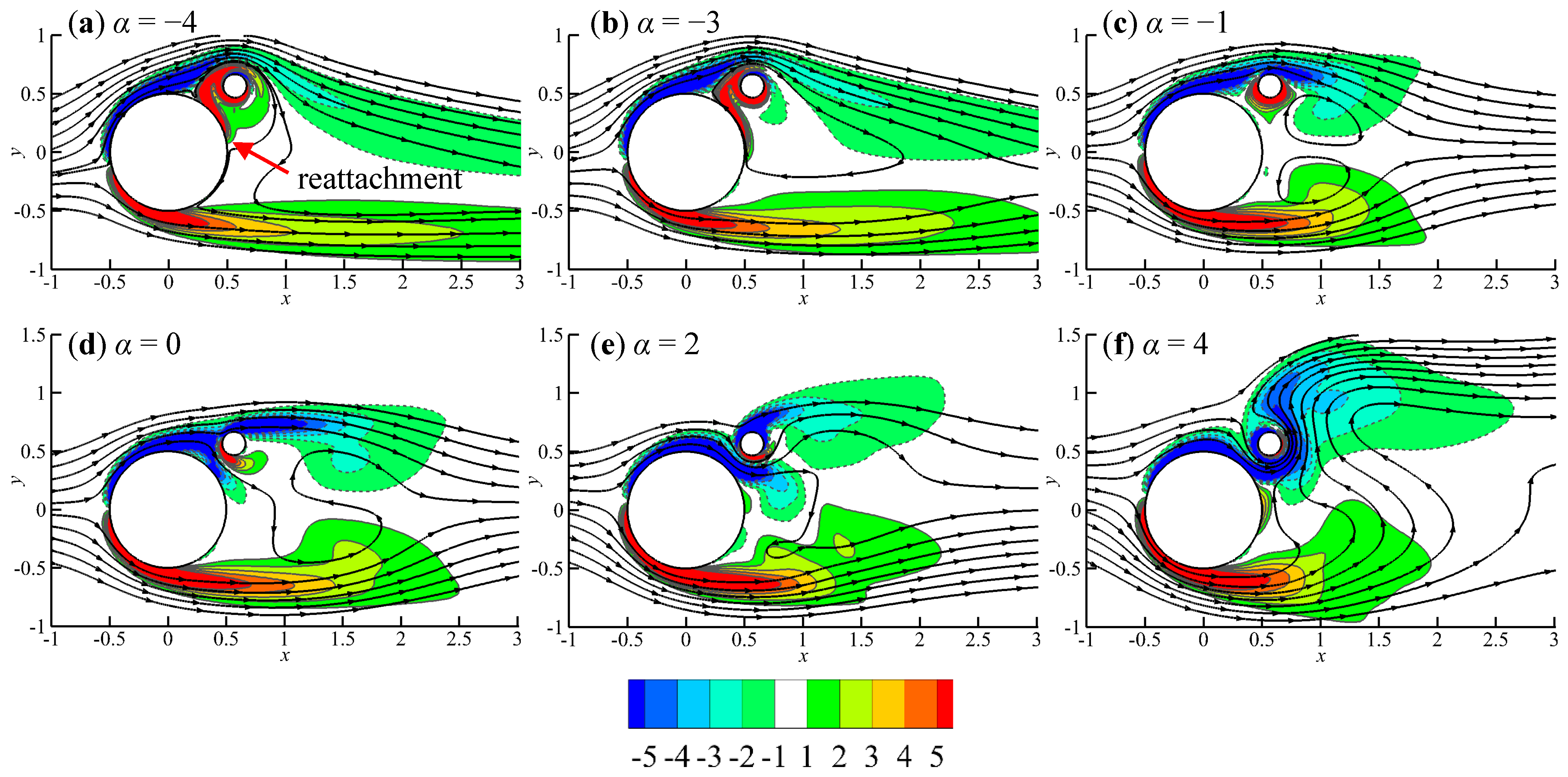
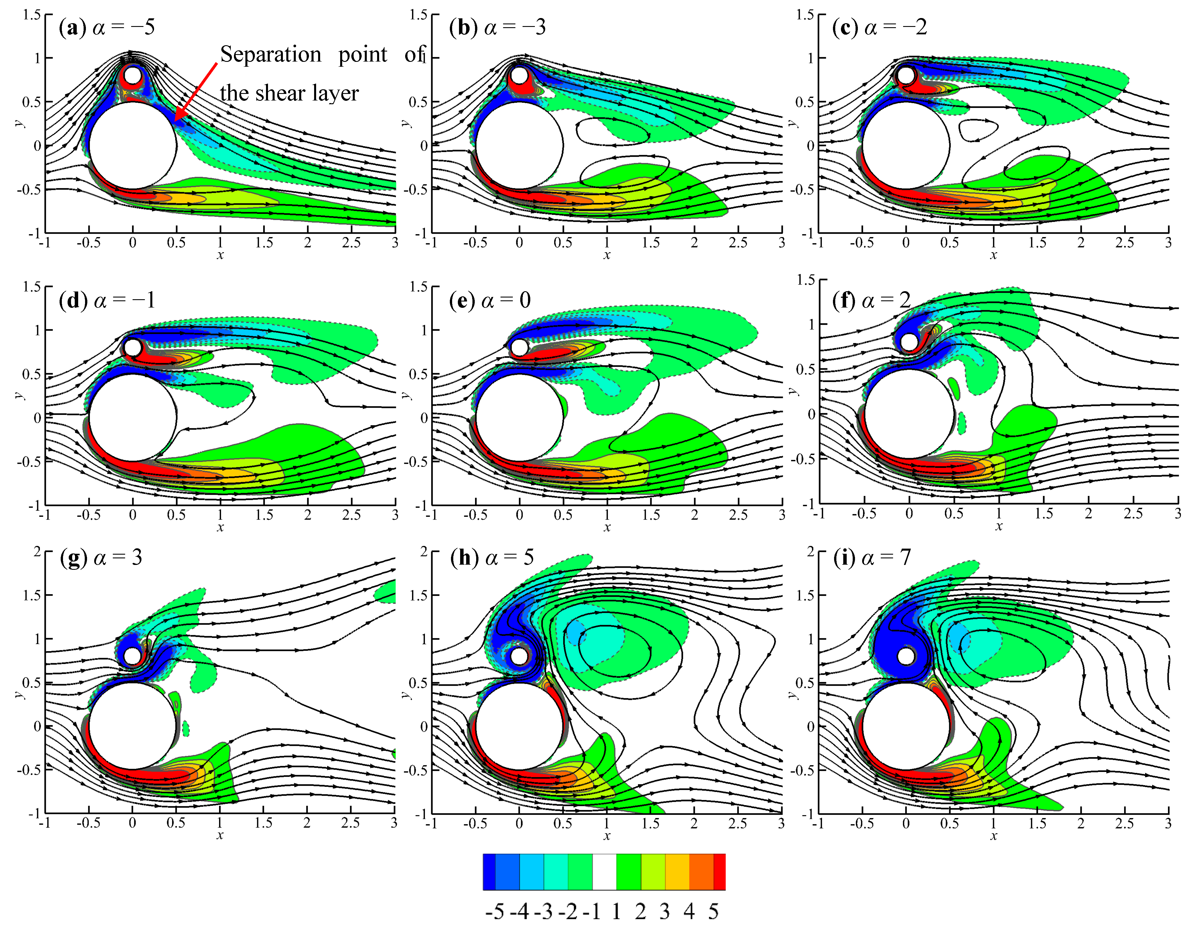
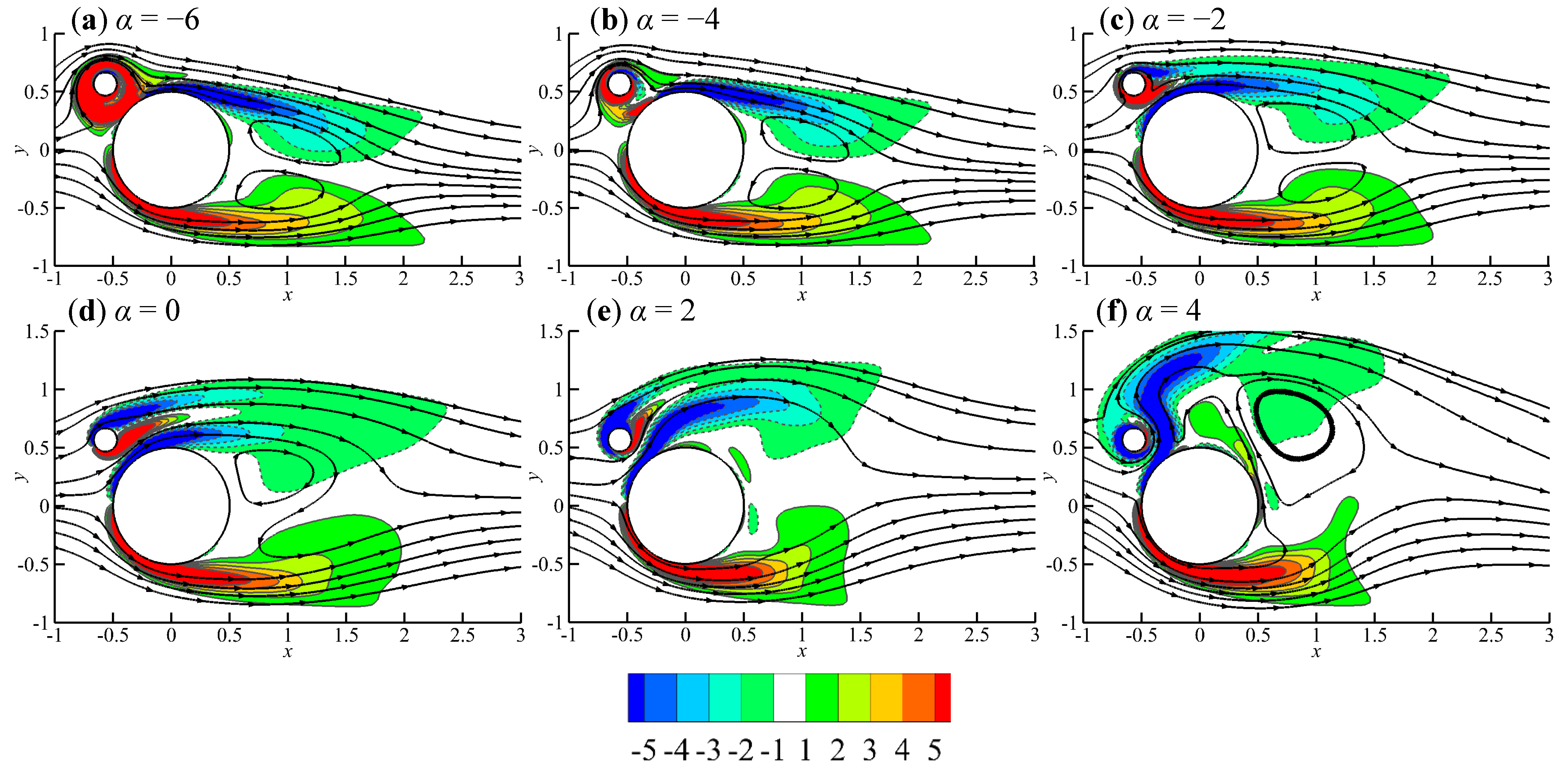
The wake vortex shedding was mainly caused by the separated negative shear layers from the top of the cylinder and rod, and the positive shear layer from the bottom of the cylinder. For
β = 45°, the negative shear layer from the top of the rod could be one that had separated from the cylinder previously and had reattached to the rod (
Figure 5). The rotation of the rod affected the flow by modifying the negative shear layers from the tops of the rod and cylinder. Positive vorticity around the rod caused by negative rotation weakened the negative shears and vice versa. The rotation of the rod at an excessively high negative rotation rate caused disappearance of the separated negative shear layer, as shown in
Figure 7a. The rotation of the rod at a very large positive rotation rate caused the disappearance of the positive shear layer, and as a result, the negative shear layer from the rod became stronger, as shown in
Figure 7f. By observing the mean flow structures and the lift coefficient in
Figure 5 and
Figure 6, the rotation of the rod can be seen to affect the flow via the following three mechanisms:
Strong negative rotation of the rod weakens the negative free shear layers;
Flow through gap interferes with vortex shedding;
Strong positive rotation of the rod enhances the negative free shear layers.
In one case, two of the above three mechanisms may co-exist and affect the flow. In the following, these three mechanisms will be discussed in detail.
4.1. Reduction of the Negative Free Shear Layers by Strong Negative Rotation of the Rod
Negative rotation of the rod generated positive vorticity, which in turn weakened the negative shear layers from both the cylinder and the rod. In
Figure 6a and
Figure 7a,b, the magnitude of the negative rotation rate was so high that the negative shear layer from the rod was totally cancelled out. As the result, the shear layer regenerated behind the rod did not have sufficient strength to form vortices, and the vortex shedding was fully suppressed. The full suppression of vortex shedding is evidenced by the zero standard deviation of the lift coefficient in
Figure 3. In the study of flow control using two rotating rods, with
d/
D = 0.05 on either side of the cylinder at Re = 100, Mittal [
21] also found a steady flow condition at
α = 5.
When
β = 45°, as shown in
Figure 5a,b, the negative shear layer, which was developed over a longer distance on the cylinder surface before it reached the rod, was not fully suppressed at
and
, though it was significantly weakened. The weakened negative shear layer from the top of the rod reduced the strength of the vortices and the lift coefficient. For
β = 135°, the upstream location of the rod allowed a new negative shear layer to be regenerated from the upstream surface of the cylinder, as shown in
Figure 7a,b, and allowed it to exist over a long distance along the cylinder. As a result, full suppression of the vortex shedding was not observed.
As the magnitude of the negative rotation rate was reduced, the negative shear layer from the top of the rod became stronger, and so did the negative vortices formed. As a result, the lift coefficient increased, as shown in
Figure 3a. However, the lift coefficient started to decrease at
for
β = 90° and
for
β = 45°. This was due to the interference of the flow through the gap.
4.2. Interference of Flow through Gap with Vortex Shedding
When the rod rotated in the negative direction with a sufficiently large rotation rate, no fluid flowed through the gap. Fluid flowed through the gap when the magnitude of the negative rotation rate was reduced to a certain level, i.e.,
for
β = 45°, 90°, and 135°, respectively. Fluid flow through the gap generated positive and negative shear layers from the rod and the cylinder, respectively. The gap flow increased as the magnitude of negative
α decreased. The strong positive shear layer from the bottom of the rod interfered with and weakened the vortex shedding process, as shown in
Figure 5d,
Figure 6d and
Figure 7d. The minimum values of the lift coefficient at
and
for
β = 45° and 90°, respectively, were caused by the interference of the flow through the gap.
For β = 135°, the positive shear layer from the bottom of the rod did not affect the vortex shedding process as much as for β = 90°, because it was weakened significantly before it reached the topmost point of the cylinder. Nevertheless, its interference resulted in the lift coefficient increasing with α much more slowly in the range of . For β = 135°, the interference of the gap flow with the vortex shedding was very weak, because the position of the gap allowed only very small volumes of fluid to flow into the gap. As a result, the minimum value of the lift coefficient caused by the interference of the flow through the gap was not observed.
4.3. Enhancement of the Negative Free Shear Layer by Strong Positive Rotation of the Rod
When the rotation rate of the rod was positive, the lift coefficient increased with an increase in the rotation speed, because the positive rotation enhanced the negative shear layer from the top of the cylinder, which was responsible for the generation of negative wake vortices, and at the same time weakened the positive shear layer from the bottom of the rod. When the positive shear layer in the gap was sufficiently weak (
Figure 5e,
Figure 6f, and
Figure 7e), the two negative shear layers combined and formed a stronger negative shear layer. If the positive rotation rate of the rod was sufficiently large, strong negative vorticity around the rod fed into the negative shear layer on top of the cylinder, as shown in
Figure 5f,
Figure 6i and
Figure 7f, resulting in a significant increase in the wake vortices and the lift coefficient.
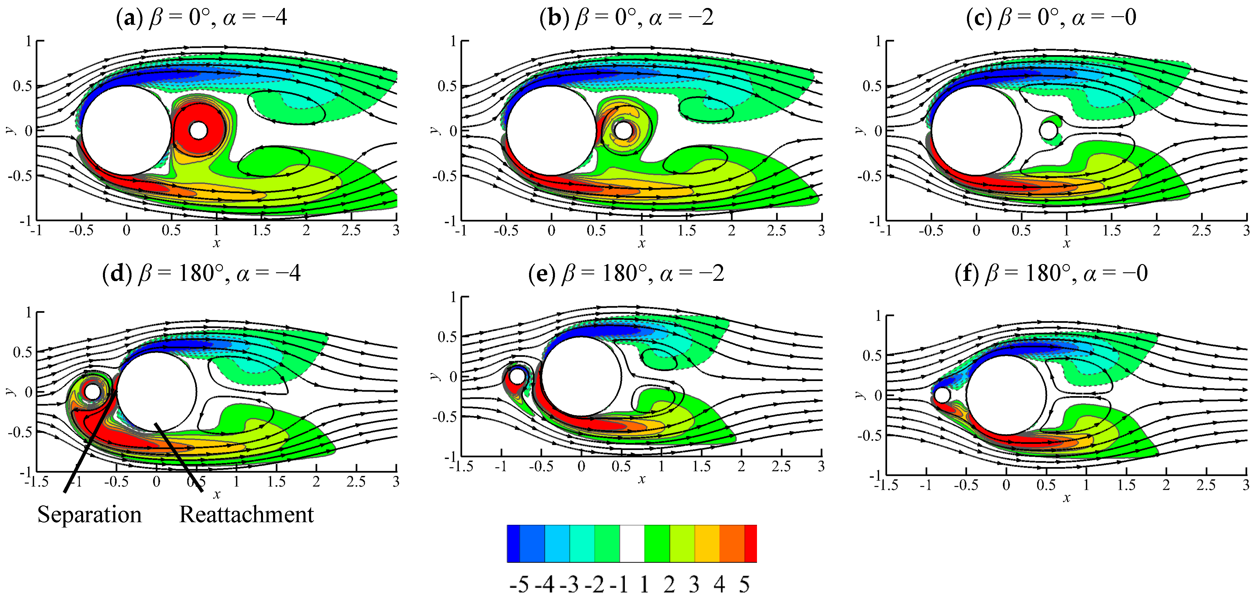
Placing the rod in the wake of the cylinder (
β = 0°) reduced the lift coefficient by half or more, regardless of the rotation direction or rotation rate, because the rod mitigated the interaction between the negative and positive vortices in the wake [
16].
For
β = 180°, the reduction in the lift coefficient caused by the rotation of the rod was found to be significant for |α| greater than
and very small for |
α| smaller than 3.2. The lift coefficient was reduced significantly when |α| ≥ 3.4, because the positive shear layer on the bottom side of the cylinder separated and reattached to the cylinder surface, as indicated in
Figure 8d–f. The separation of the shear layer for a certain distance before it reattached to the cylinder reduced its strength and consequently weakened the vortex shedding. For |α| ≤ 3.2, the rotation of the rod did not cause a large change in the lift coefficient, because it enhanced the positive shear layer and at the same time weakened the negative shear layer on the cylinder surface.
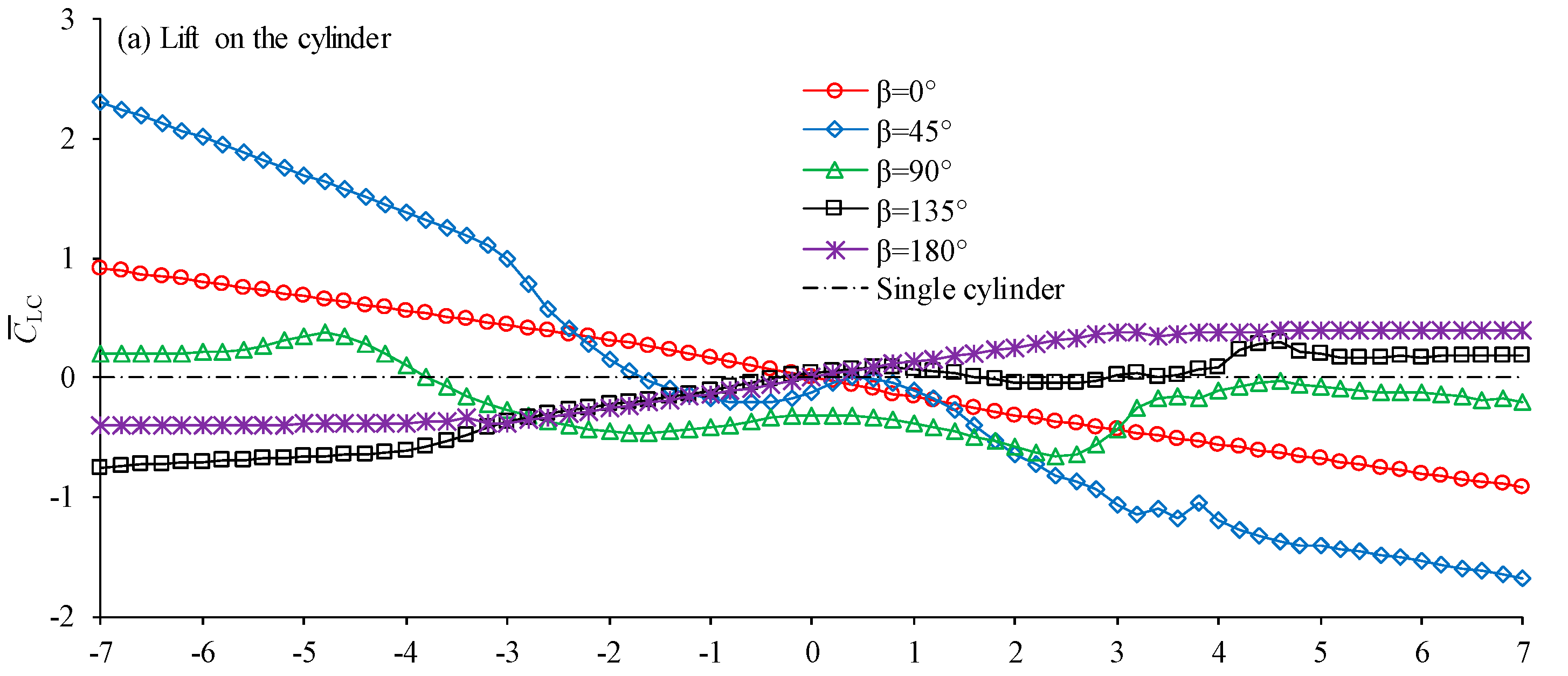
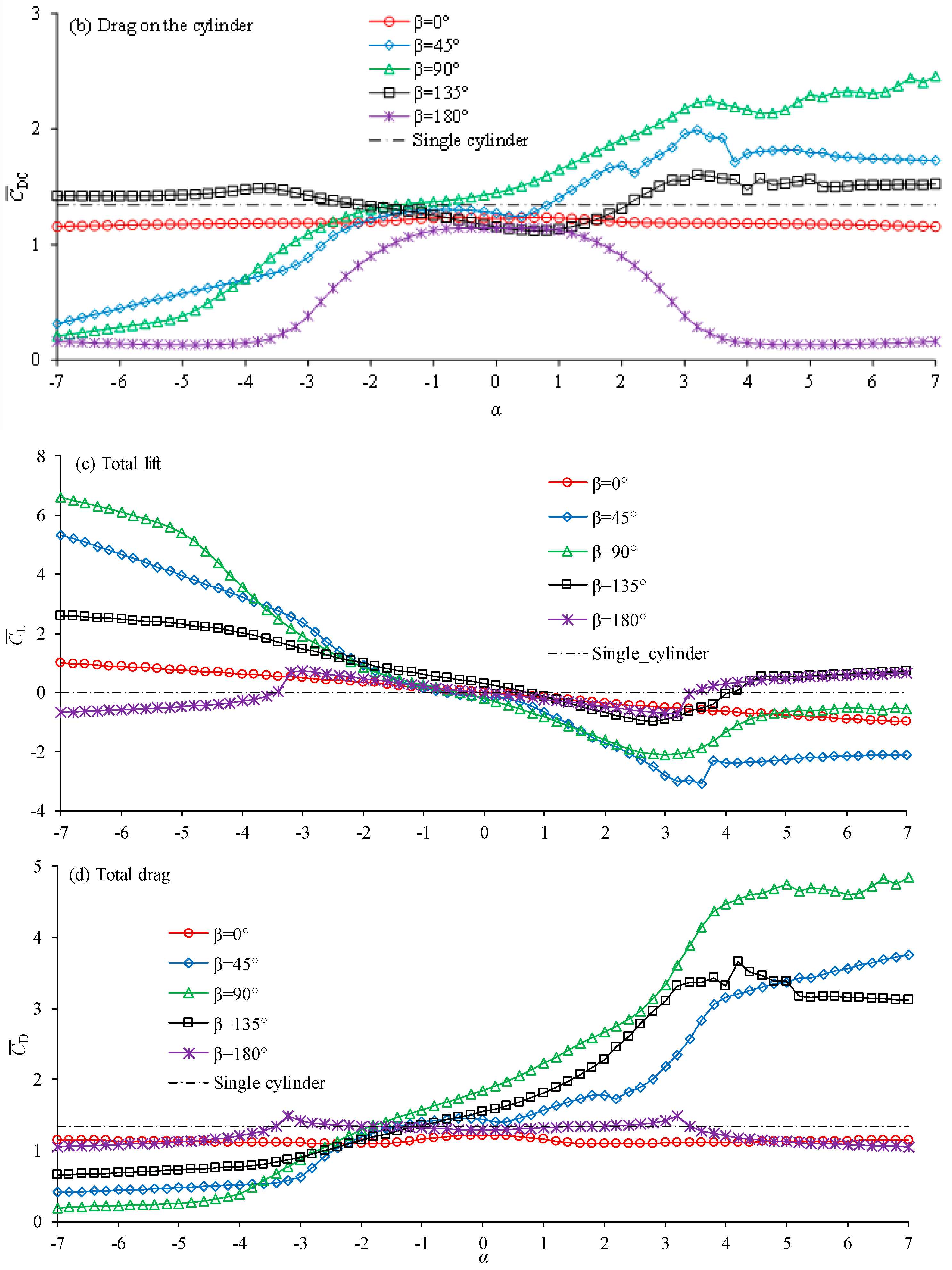
Figure 9 shows the variation in the mean lift and drag coefficients with rotation rate. An overbar on
CD and
CL denotes the mean value. Both the mean lift coefficient of the cylinder and the total lift coefficient were significantly increased at large rotation rates, either in the negative or positive directions. The mean lift coefficient for the highest |α| was greater than the mean drag coefficient for
β = 45°. A net lift coefficient could be avoided by placing two control rods either side of the cylinder. The mean total drag coefficient at large negative rotation rates was reduced compared with the case without a control rod.
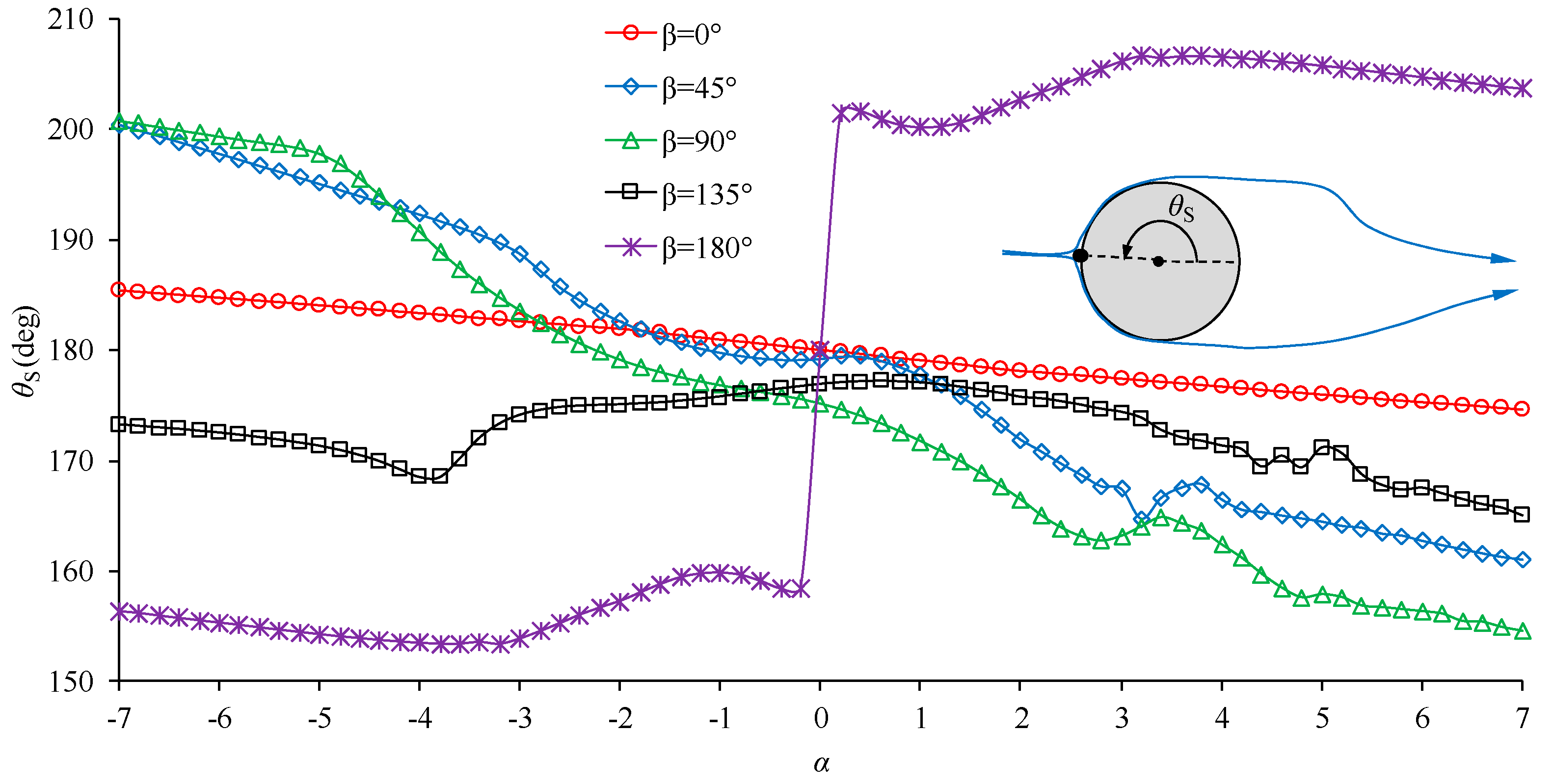
Figure 10 shows the position angle of the stagnation point upstream of the cylinder (
θs), which is referred to as the stagnation angle. The stagnation angle is 180° if the control rod does not exist. It can be seen that for
β = 0°, 45°, and 90°, the stagnation point in front of the cylinder shifted downwards (
θs > 180°) if
α was negative and upwards (
θs < 180°) if
α was positive. The downward and upward shift of the stagnation point caused positive and negative net lift coefficients, respectively. The effect of the rotation direction on the stagnation point for
β = 135° and 180° was opposite to that for
β = 0°, 45°, and 90°, i.e., a negative and positive α caused an upward and downward shift of the stagnation point, respectively, on the front surface of the cylinder.
5. Conclusions
The effectiveness of flow control using a rotating control rod was investigated through two-dimensional numerical simulations for Re = 200, d/D = 0.2, G/D = 0.2, and β = 0°, 45°, 90°, 135°, and 180°. Simulations were conducted for a wide range of rotation rates between −7 and 7. The study was focused on the interference of the rod with the shear layers in cases where the rod was very close to the cylinder. The main conclusions can be summarized as follows.
When the rod was placed at the side (β = 90°,) or nearly to the side of the cylinder (β = 45° and 135°), its rotation interfered with the shear layers in the following three ways, depending on the rotation rate: (1) strong negative rotation of the rod weakened the negative free layers, and as a result, the lift coefficient was reduced strongly; (2) the interference of the flow through the gap weakened the vortex shedding and reduced the lift coefficient; and (3) strong positive rotation of the rod enhanced the negative free shear layers and increased the lift coefficient.
The SD of the lift coefficient was significantly reduced for a rotation rate |α| ≤ −4 for all the position angles. The vortex shedding could be fully suppressed for β = 90° and 45° if the magnitude of the negative rotation rate was sufficiently large. A positive rotation rate caused a significant increase in the SD of the drag and lift coefficients if β = 45°, 90°, or 135°. Rotation of the rod with β = 0° and 180° caused a reduction in the SD of the lift coefficient, regardless of rotation rate.
The rotation of the cylinder in either the negative or positive direction created a mean lift coefficient on the cylinder, which increased as the rotation rate increased. The mean total drag coefficient at a large negative rotation rate was reduced compared with the case without a control rod.


