Article

Asymmetrical Oscillating Morphology Hydrodynamic Performance of a Novel Bionic Pectoral Fin

1
School of Marine Science and Technology, Northwestern Polytechnical University, Xi’an 710072, China
2
Unmanned Vehicle Innovation Center, Ningbo Institute of NPU, Ningbo 315103, China
*
Author to whom correspondence should be addressed.
J. Mar. Sci. Eng. 2022, 10(2), 289; https://doi.org/10.3390/jmse10020289
Submission received: 15 December 2021 / Revised: 5 February 2022 / Accepted: 11 February 2022 / Published: 19 February 2022
(This article belongs to the Special Issue Frontiers in Deep-Sea Equipment and Technology)

Abstract

:
This research proposes a novel bionic pectoral fin and experimentally studied the effects of the oscillation parameters on the hydrodynamic performance of a bionic experimental prototype. Inspired by manta rays, the bionic pectoral fin was simplified and modeled based on the natural pectoral fin skeleton structure and oscillation morphology of this underwater creature. A dual-degree-of-freedom bionic pectoral fin was designed. The active spatial motion was realized by the space six-link mechanism driven by two motors, and the passive deformation was achieved by carbon fiber. The motion analysis of the bionic pectoral fin proves that the pectoral fin can realize an “8”-shaped spatial trajectory. An experimental prototype was developed accordingly. The experimental prototype could flap between 0.1 Hz and 0.6 Hz and produce a maximum thrust of 20 N. The hydrodynamic performance under different oscillation parameters was studied experimentally in a water pool. The experimental results indicate that the hydrodynamic performance of the pectoral fin oscillation is closely related to the motion equation parameters including the amplitude, frequency, phase difference, and initial bias. In addition to considering the impact of parameters on thrust and lift, the influences of asymmetrical oscillation on the position of the equivalent point were also studied. The results show that the pectoral fin proposed in this research exhibited the expected spatial deformation and outstanding hydrodynamic performance. The obtained results shed light on the updated design and control of a bionic robot fish.

1. Introduction

After tens of thousands of years of evolution, fish in nature now show excellent performance in many aspects such as swimming efficiency, mobility, stability, and noise level [1], which has attracted extensive attention from researchers worldwide in recent years [2,3,4,5]. The different propulsion modes of fish can be mainly divided into the following two categories: body and caudal fin propulsion (BCF) and median and paired fin propulsion (MPF) [6,7]. The BCF mode is the most common mode in nature; at present, researchers have performed many studies on the bionic propulsion mechanism of the BCF mode and have developed a variety of prototypes with different motion characteristics [8,9,10,11]. With the continuous development of bionic fish research, researchers have gradually turned their bionic objects to Myliobatidae (such as eagle rays, cownose rays, manta rays, etc.), the representative creatures of MPF mode [12]. Compared with the BCF mode, fish adopting the MPF mode have higher stability when swimming at low speed [13]. In addition, the large aspect ratio of Myliobatidae enables excellent gliding performance and can be applied to broader practical application prospects [14]. Therefore, the bionics of the MPF mode have attracted increasing attention [7].
Because of the advantages of the MPF model, researchers worldwide have carried out many studies on oscillating pectoral fins. The authors of [12] and [15] used computerized tomography (CT) and skeleton coloration methods, respectively, to study the skeleton structure and skeleton calcification degree of pectoral fins; they revealed that the flexibility distribution of pectoral fins gradually increased from the leading edge to the trailing edge and from the fin root to the fin tip. Studies [16] and [17] obtained much data by observing natural creature swimming. The observation results indicated that the oscillation form of the pectoral fin (such as the amplitude, frequency, phase difference, etc.) is closely related to the swimming performance of a natural creature. Based on the above biological studies, researchers later carried out many studies on bionic pectoral fins and bionic robotic fish. Researchers from Princeton University studied the relationship between the wake shape and efficiency of a batoid-inspired oscillating fin by using the particle image velocimetry (PIV) method [18]. Their results proved that the bifurcation distance of wake decreased with increasing frequency and decreasing phase difference, and it was shown to obey a simple scaling law. The researchers from the University of Virginia studied the hydrodynamic performance by using the CFD method [14,19]. The results showed that the trajectory of the pectoral fin endpoint in space has the form of an “8”, and the distal part of the fin generates the most thrust force. In researching bionic robotic fish aspect, researchers from the University of British Columbia [20] built a two-dimensional pectoral fin with shape memory alloys (SMAs) to explore the application of vibration motion. In addition, other researchers have produced manta ray robotic fish by using soft actuators such as ion-exchange polymer metal composite (IPMC) [21,22] and dielectric elastomer (DE) [23,24]. The application of soft actuators is still in the stage of manufacturing small-scale laboratory prototypes. At present, the most popular actuator is the imitation manta ray robotic fish driven by traditional motors. Researchers from the Chinese Academy of Sciences proposed an improved crank rocker mechanism for a bionic specific fin robotic fish that can change the pitch maneuverability by changing the sweep angle of the pectoral fin, and carried out a free-swimming experiment [25]. Researchers from Beihang University developed a bionic flapping pectoral fin with controllable spatial deformation and tested its thrust and lift in a towing tank [26].
Most of the previous research has mainly focused on the symmetrical oscillation propulsion performance in forward swimming. What is not yet clear is the impact of asymmetrical oscillation on hydrodynamic performance. In this research, in addition to the hydrodynamic performance in forward swimming, the impact of asymmetrical oscillation on pitching, turning, and rolling is emphatically discussed. There are two ways to adjust the pitch of underwater vehicles. One approach is to adjust the position of the mass center, but this will occupy a lot of internal space and is not conducive to carrying a payload; the other approach is to adjust the angle of the caudal fin, similar to an aircraft changing the rudder angle, but the adjustment effect of this method is highly dependent on the swimming speed. For the low-speed swimming mode such as the mode of pectoral fin oscillation, the adjustment effect is not apparent. Yawing and rolling are not independent motion states, and yawing turns are accompanied by rolling of the entire body [27].
Based on the above research results, this paper proposed a new type of bionic pectoral fin and experimentally explored the relationship between oscillation morphology and hydrodynamic performance. First, a dual-degree-of-freedom (2-DOF) pectoral fin consisting of two parts was constructed. The two parts included a spatial connecting rod mechanism for generating spanwise and chordwise waves and a pectoral fin plate for wave transmission. Second, an experimental prototype was built, and the ability of the bionic pectoral fin to generate thrust in the experimental prototype was verified. Moreover, the effects of the pectoral fin oscillation on the pitching, yawing, and rolling hydrodynamic performance were analyzed. This research can provide new ideas for the realization of high maneuverability underwater bionic robots.
The rest of this article is organized as follows. Section 2 describes the mechanical design and motion analysis of the bionic pectoral fin. The experimental settings and analysis of the results are presented in Section 3. Finally, conclusions and future work are given in Section 4.

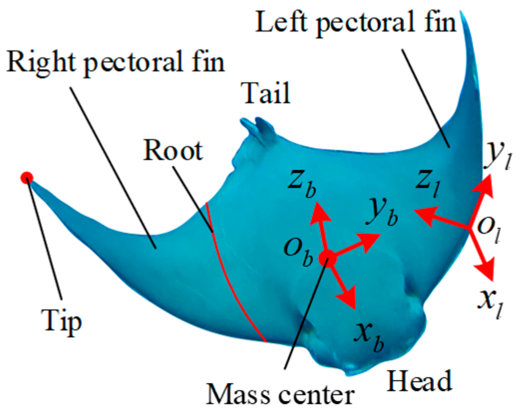
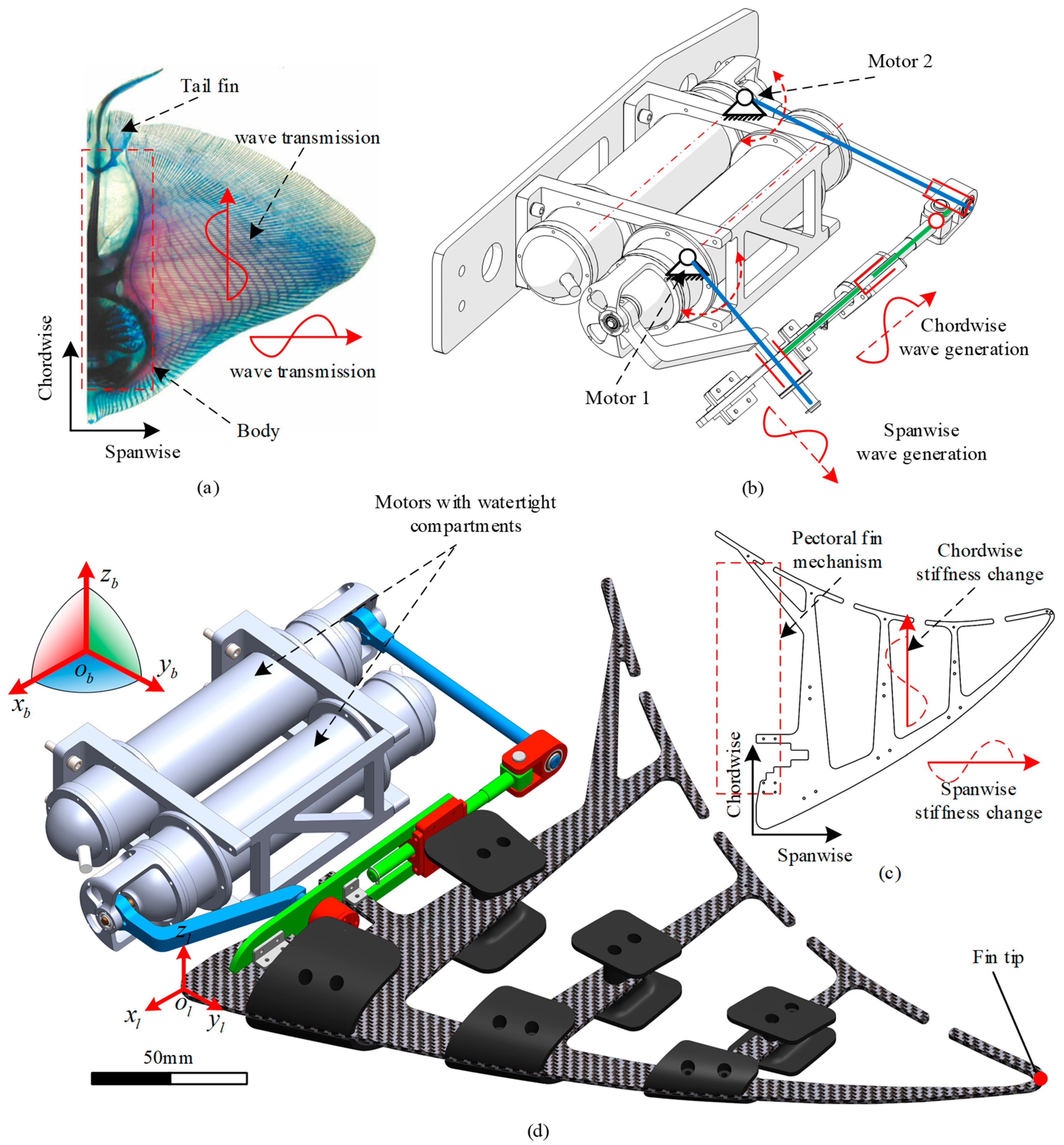
2. Bionic Pectoral Fin Design and Analysis

MPF mode fishes can produce thrust and realize complicated maneuvers by oscillating their pectoral fins. The Supplementary Materials show the free swimming of different kinds of MPF mode fishes. The series snapshots indicate that there are waves generated from the root of the pectoral fin, where such waves transmit spanwise from the root to the tip and chordwise from the leading edge to the trailing edge. To describe the movement of the pectoral fin clearly, the body frame C b = o b x b y b z b is defined to be fixed on the mass center of the entire body, as shown in Figure 1. Since the pectoral fins on both sides are completely symmetric, only the left fin is presented. The fin-fixed frame is defined as C l = o l x l y l z l , the origin point o l coincides with the point at the root of the leading edge of the pectoral fin, and x l o l y l always overlaps with the pectoral fin. The later analysis in this research mainly focuses on the left pectoral fin, and various parameters of the right pectoral fin can be obtained based on the symmetrical relationship.

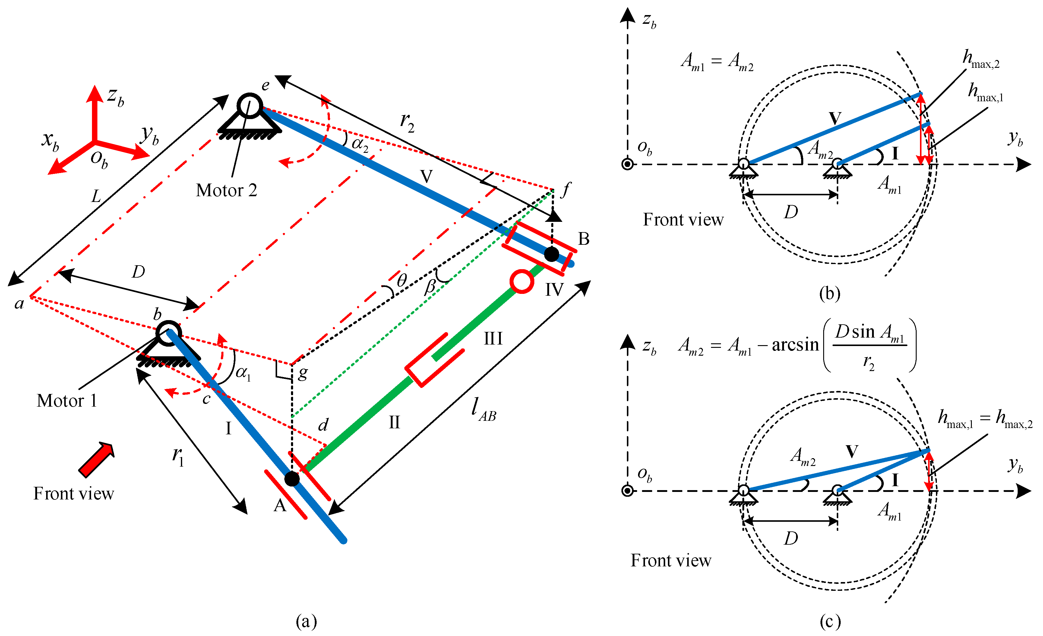
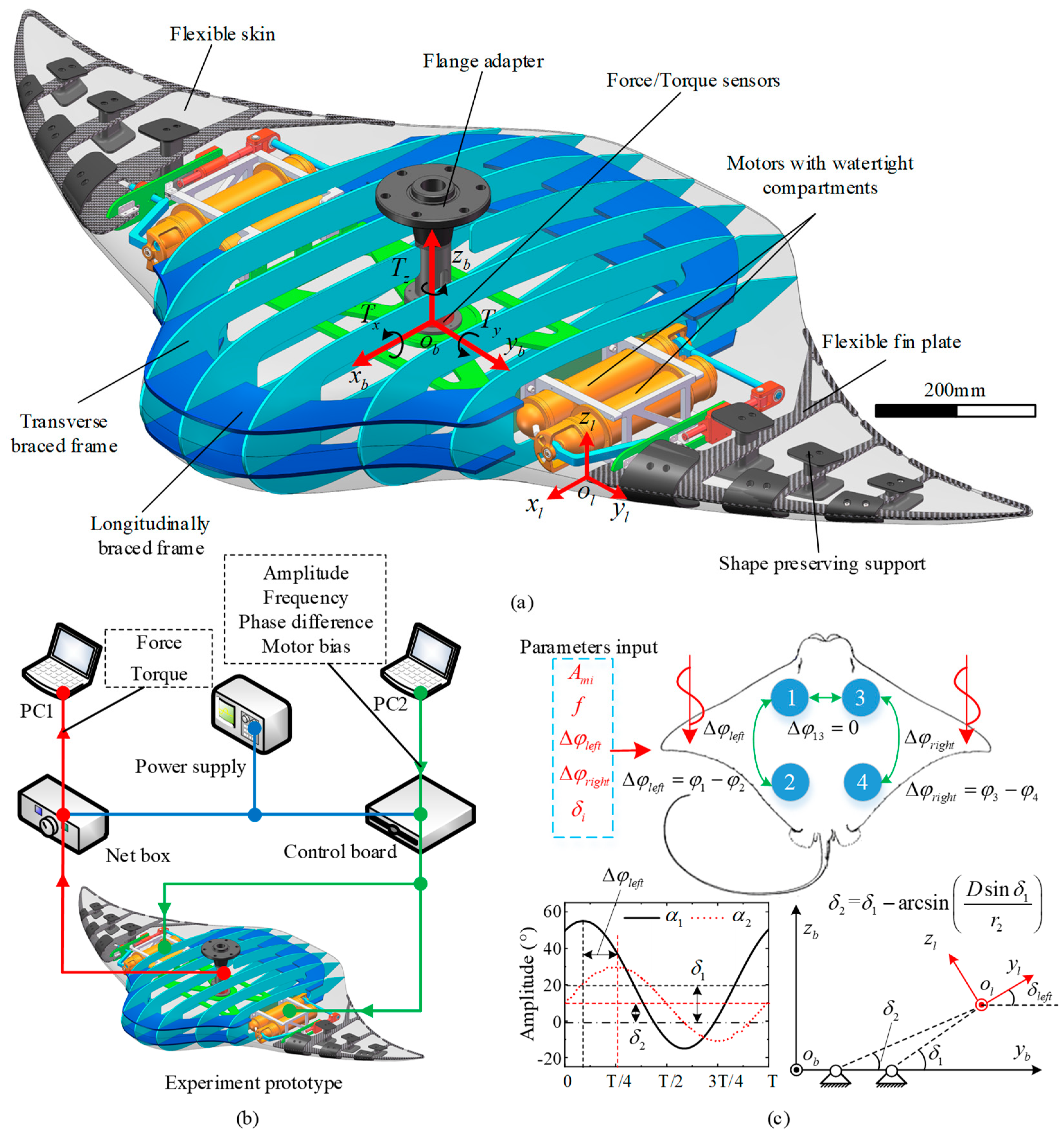
2.1. Mechanical Design of Bionic Pectoral Fin

According to the modality of pectoral fin oscillation and wave transmission, the design of bionic pectoral fins can be divided into the following two aspects. On one hand, the driving structure that is used to generate waves should be able to realize the active control of pectoral fin oscillation characteristics such as the amplitude, frequency, and phase difference. On the other hand, the fin surface that can realize wave transmission should be flexible and have a passive deformation capability.
Inspired by the degree of skeletal calcification of the pectoral fin [15], as shown in Figure 2a, the fluctuation on the pectoral fin can be regarded as the synthesis of spanwise and chordwise wave generation and transmission. In this research, we first propose a novel spatial linkage mechanism to generate waves, as shown in Figure 2b. This mechanism is located on one side of the body. At the root of the pectoral fin, the mechanism is driven by two reciprocating motors connected by linkages, where the regular swing of the motors can produce spanwise and chordwise waves. Furthermore, according to the calcification of the pectoral fin, wave transmission is realized by the uniform thickness carbon fiber fin plate, as shown in Figure 2c. After several tests, the thickness adopted in this research was 2.5 mm. The root of the fin plate is fixed to the pectoral fin mechanism, and the stiffness and passive deformation capacity are changed by changing the cross-sectional area; this method is consistent with the calcification of the pectoral fin skeleton. Finally, the pectoral fin mechanism and fin plate are combined to obtain a bionic pectoral fin with two degrees of freedom, as shown in Figure 2d. C b is fixed on the mass center of the entire experimental prototype, which is described in detail in Section 3. C l coincides with the root of the leading edge, and the motors with watertight compartments can work smoothly under 10 MPa pressure, making them capable of working in deep-sea environments. Considering the reliability for underwater use, prototype size, power supply voltage, control method, and many other factors, the brushless motor EC-max30 and planetary gear reducer GP 32C produced by Maxon were chosen as the actuate motors. The rated power of the motors was 60 W, and the rated torque of the motors was 5.7 N∗m when the supply voltage was 24 V. The experiment proves that the motors can fully meet the requirements of this paper.
To facilitate the description of the moving process of the bionic pectoral fin mechanism, the mechanism shown in Figure 2b can be simplified as the schematic wireframe shown in Figure 3a. Components I and V are driven by motor 1 and motor 2, respectively. Components I and II, II and III are connected by cylindrical pairs, and components III and IV, IV and V are connected by rotating pairs. α 1 and α 2 represent the angles between components I, V, and x b y b z b , respectively. r 1 represents the effective length of component I. For point A, which is the intersection of components I and II that changes over time, the effective length r 1 is not a constant value but changes over time, while r 2 , the length of component V, is a constant value. l A B , the length between points A and B, also changes over time. θ represents the angle between x b o b z b and l f g , the projection of l A B on x b o b y b , and β represents the angle between l A B and x b o b y b . The oscillation of the pectoral fin is similar to sinusoidal motion, so α 1 and α 2 can be prescribed as a sinusoidal equation:
α i = A m i sin ( ω i t + φ i ) + δ i i = 1 , 2
Equation (1) contains all motion parameters, A m i represents the amplitude, which is the maximum angle at which components I and V deviate from the x b o b y b plane, ω i is the rotation angular velocity of components I and V, where its magnitude is equal to 2 π f , and f is the frequency. In this research, the frequencies of driven motors are equal to each other and can be written as ω i = ω . φ i represents the phase of the two components. There is a phase difference Δ φ between components when the φ i values are different from each other. δ i represents the bias angle deviating from the x b o b y b plane. When the pectoral fins oscillate symmetrically about the x b o b y b plane, δ i = 0 . When δ i 0 , the pectoral fin oscillates symmetrically about a new plane with an angle δ l e f t between the new plane and x b o b y b .
Furthermore, the effective length r 1 is formulated as:
r 1 = D sin α 2 sin ( α 1 α 2 ) + [ r 2 D sin α 1 sin ( α 1 α 2 ) ] cos ( α 2 α 1 )
where D is the spanwise distance between the rotation centers of the two motors, and the length change in r 1 is manifested as the stretching and contraction of the pectoral fin in the spanwise direction. θ and β can be calculated as:
{ θ ( t ) = arctan ( D ( cos α 1 cos 2 α 1 ) L + r 2 cos ( α 2 α 1 ) L sin ( α 1 α 2 ) ) β ( t ) = arctan ( cos θ cos α 1 r 2 sin ( α 1 α 2 ) D sin α 1 L )
where L is the chordwise distance between the rotation centers. Furthermore, the length of l A B can be calculated as:
l A B = L cos β ( t ) cos θ ( t )
The length change in l A B is manifested as the chordwise stretching and contraction of the pectoral fin. During the oscillation of the bionic pectoral fin, the changes in θ and β can be regarded as the circular motion of point A around point B, so the angular velocities of θ and β can be expressed as:
{ ω θ = [ ω A ( r 2 cos ( α 2 α 1 ) D cos α 1 ) sin α 1 ω B r 2 sin α 2 ] cos θ L ω β = [ ω A ( r 2 cos ( α 2 α 1 ) D cos α 1 ) cos α 1 ω B r 2 cos α 2 ] cos θ L
Because the rotation centers of motors 1 and 2 are misaligned, the rotation radius of component V is much longer than r 1 . When A m 1 = A m 2 , as shown in Figure 3b, the distances between the x b y b z b plane and the endpoints of components I and V are h max , 1 and h max , 2 , respectively, where h max , 1 < h max , 2 leads to an excessive amplitude at the trailing edge of the fin plate. To ensure that the endpoints of the two driving components reach the same height, the amplitude of component V needs to be compensated and corrected. The revised results are shown in Figure 3c.

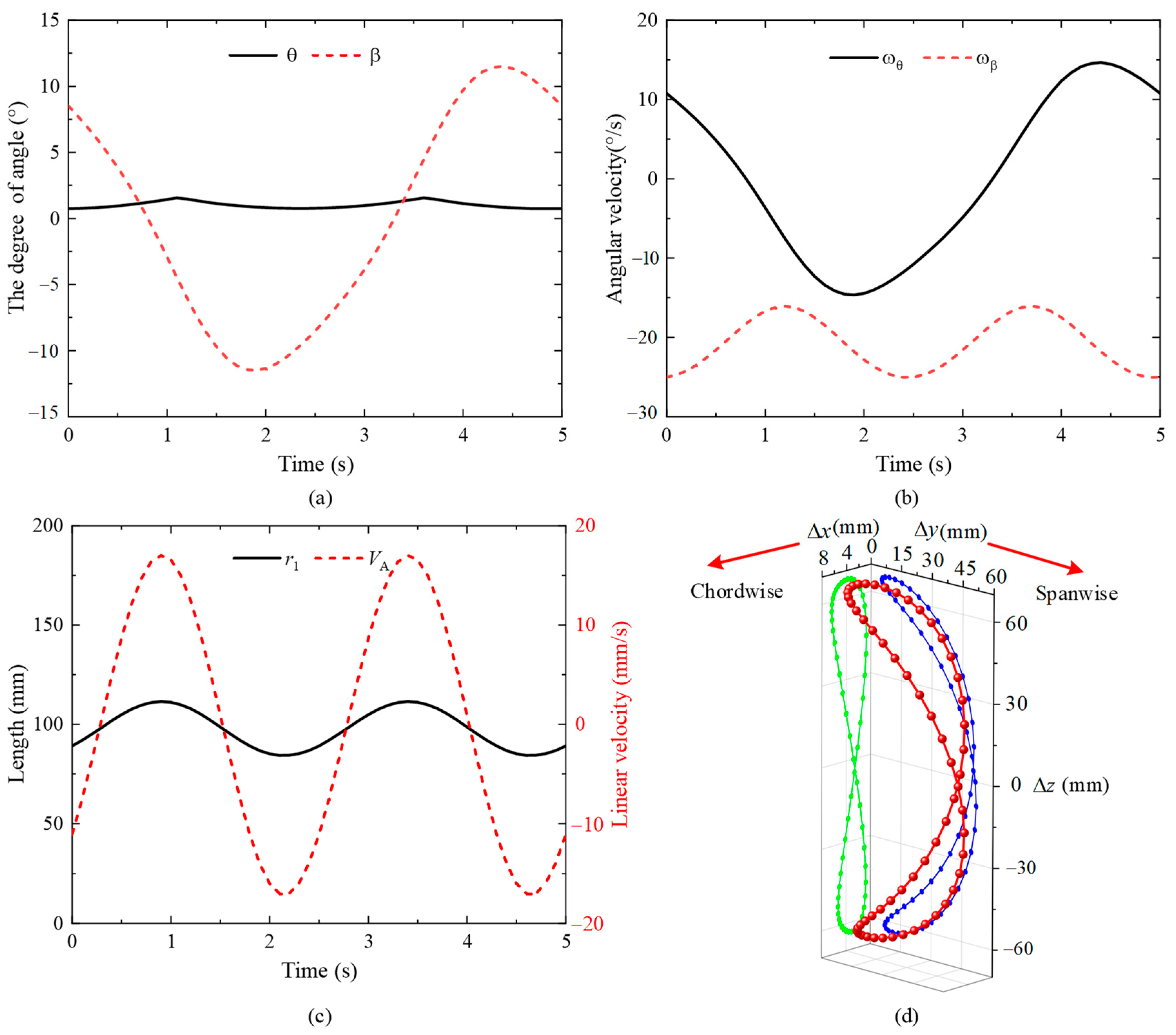
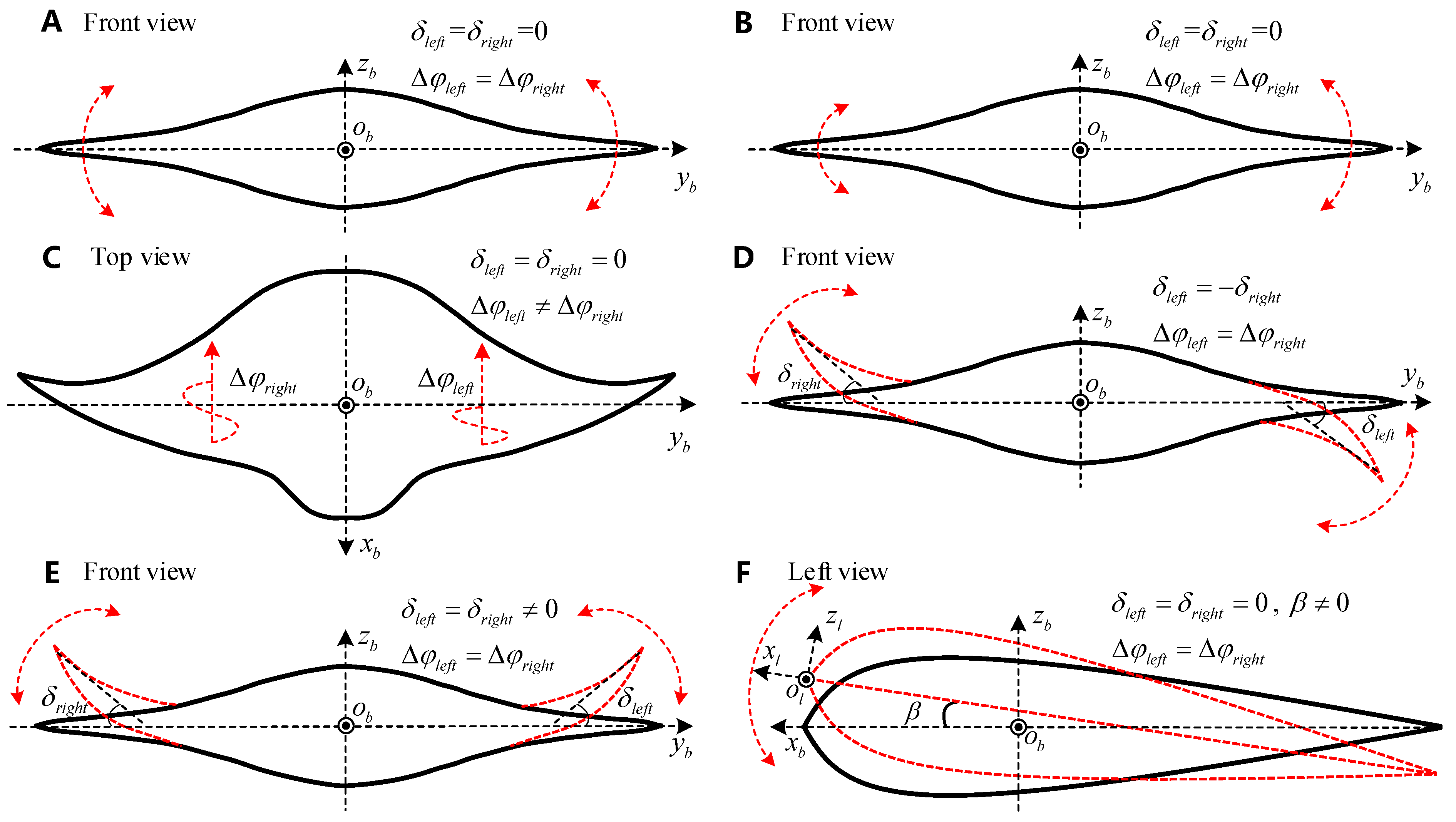
2.2. Bionic Pectoral Fin Motion Analysis Results

After the above design and calculation, D = 80   mm , L = 315   mm , r 2 = 185   mm , A m 1 = 35 ° , f = 0.2   Hz , Δ φ = 20 ° , and δ i = 0 were taken as an example. In this situation, the pectoral fins oscillate symmetrically about the x b o b y b plane. Utilizing Solidworks to perform the motion analysis, the corresponding simulation results are shown in Figure 4. Figure 4a,b indicate that the periods of θ and ω θ are twice those of β and ω β , respectively. It is known that the linear velocities of point A and point B can be expressed as V A = ω r 1 and V B = ω r 2 , respectively; V B is constant during the entire oscillating period, while the V A performance varies. As the intersection of components I and II, its spatial trajectory and velocity are only related to the motion of the space six-link mechanism. Because the value of r 1 shown in Figure 4c changes over time, V A still follows a sinusoid law. The period of r 1 and V A is 0.5 times that of the pectoral fin oscillation because there are two processes, upstroke and downstroke, in one oscillation period. The upstroke and downstroke can be regarded as the same movement process, but with opposite directions of oscillation.
Figure 4d shows the trajectory of the left pectoral fin coordinate origin o l . The red line is the spatial trajectory, and the green and blue lines are the projections of the spatial trajectory onto x b o b z b and y b o b z b , respectively. It is evident that the spatial trajectory and the projections are similar to the Roman number “8”. The projections indicate that there are spanwise and chordwise displacements. This trajectory is similar to the flapping movement of many birds and insects. Combined with the previous calculation and simulation analysis, the bionic pectoral fin mechanism proposed in this paper can produce displacement along the spanwise and chordwise directions, it can generate waves transmitting along the spanwise and chordwise directions, and it can better realize the active movement control of the pectoral fin spanwise and chordwise.

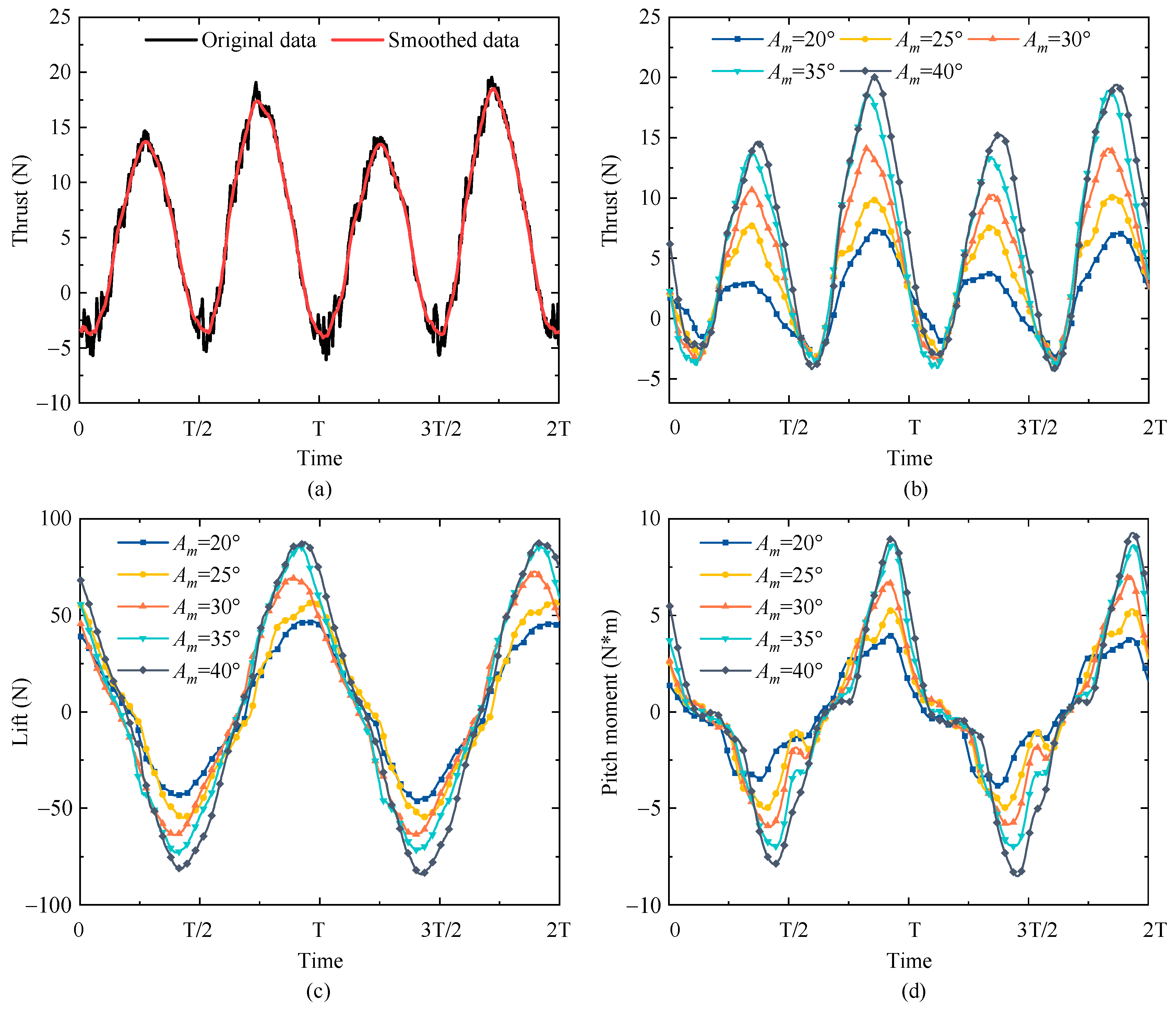
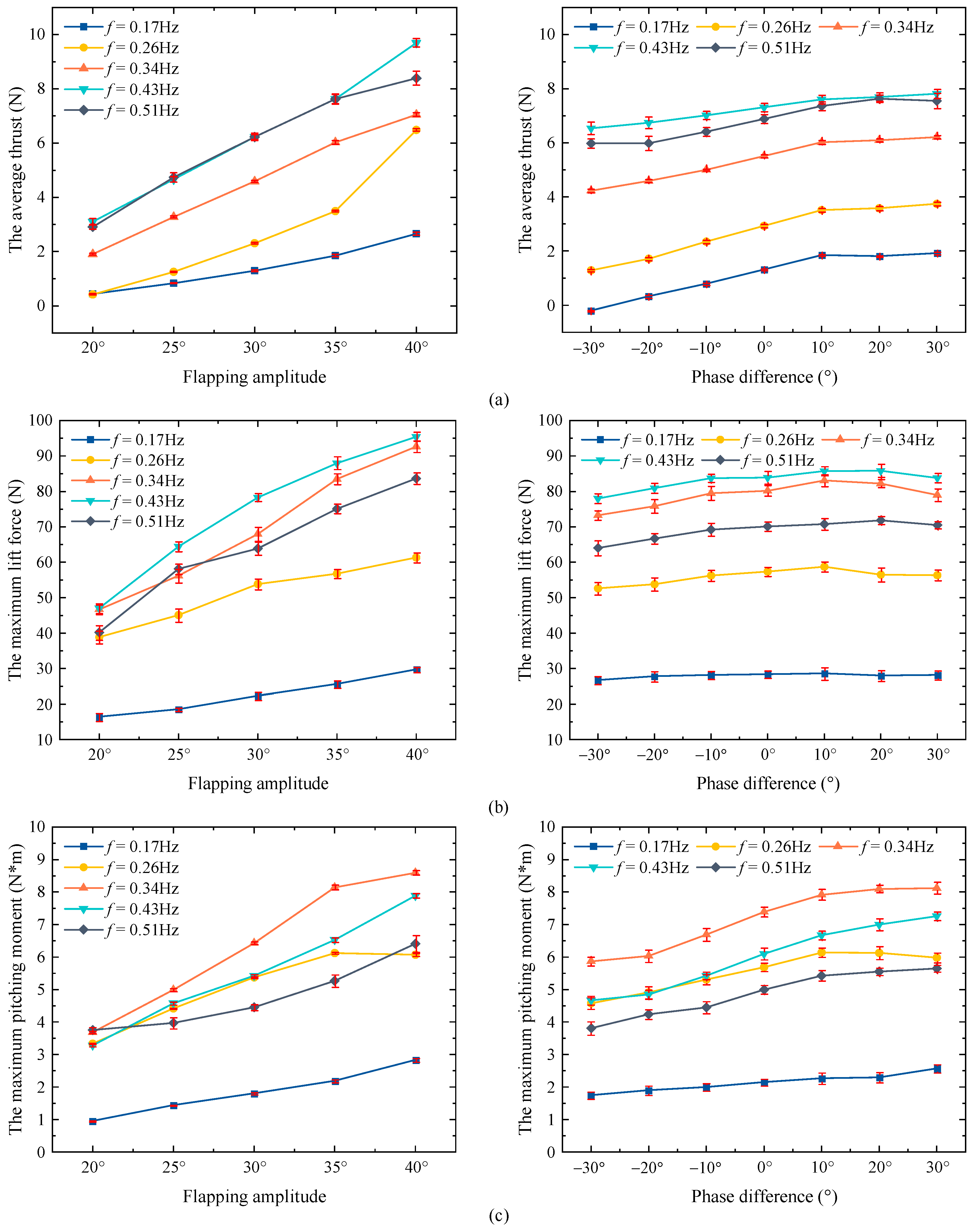
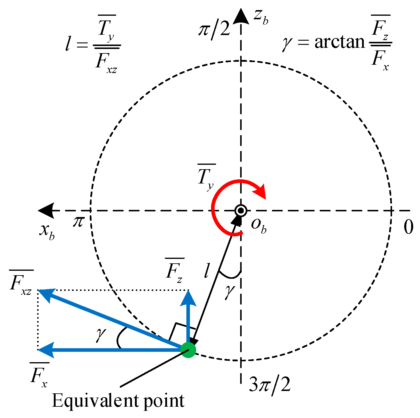
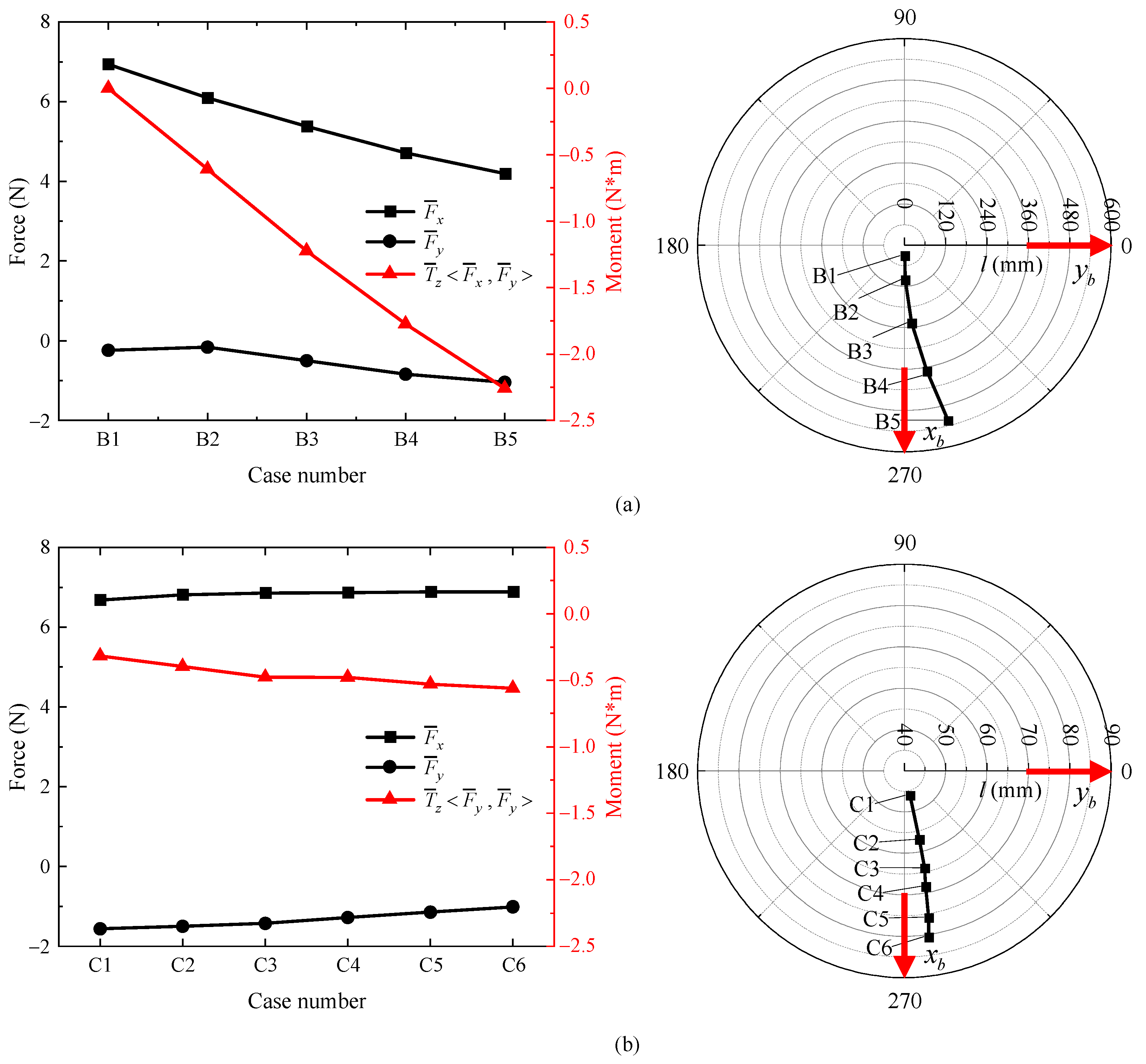
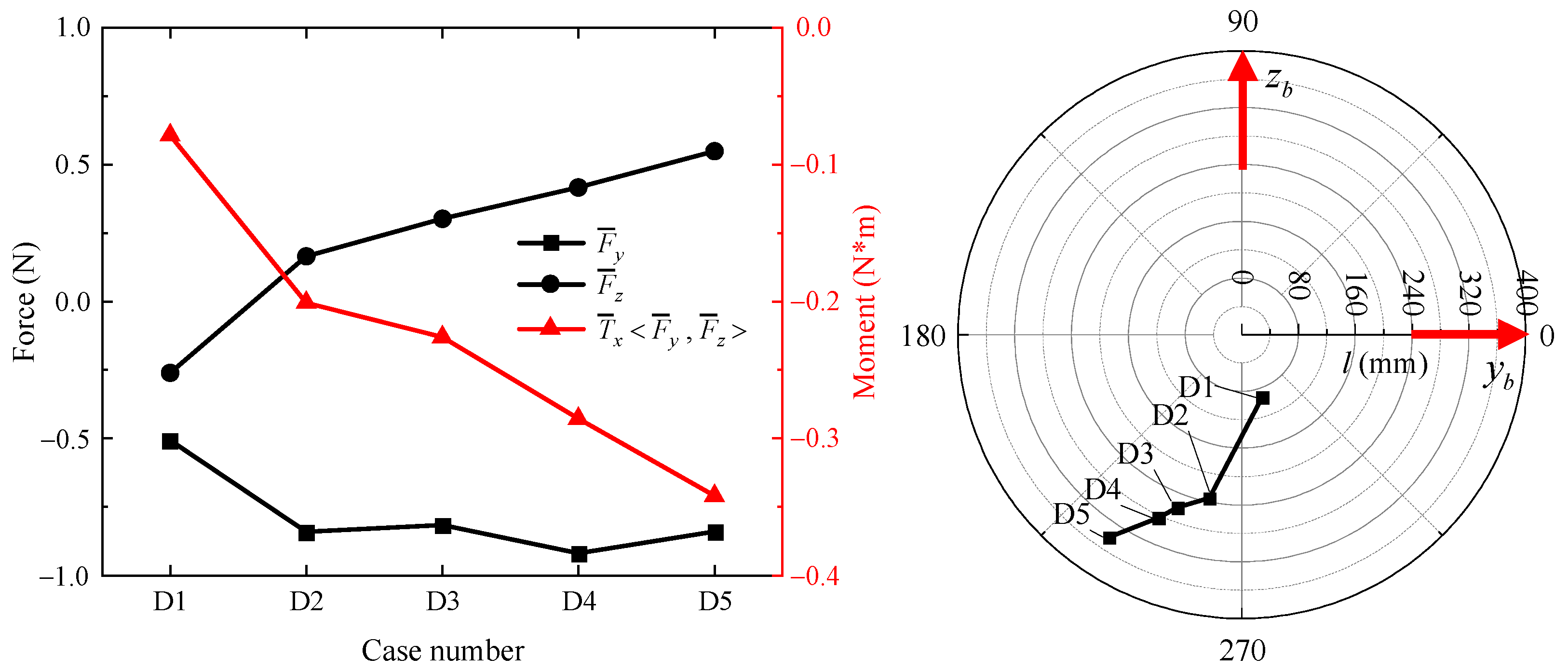
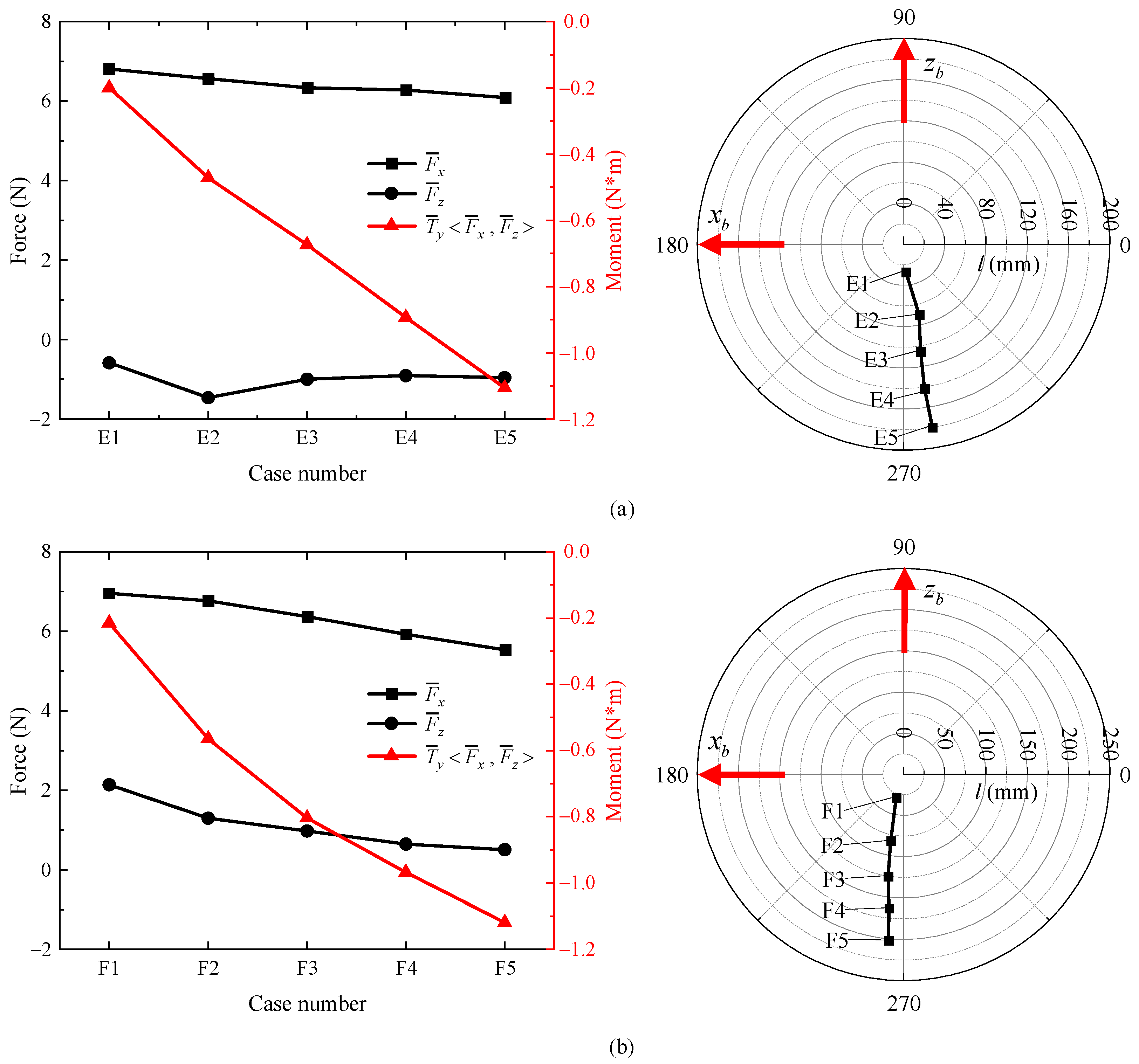
3. Experimental Results and Discussion

In this section, an experimental prototype was built, and the influences of the oscillation parameters on the hydrodynamic performance (thrust, lift, and literal force; pitching, rolling, and yawing moment) were studied experimentally and discussed.

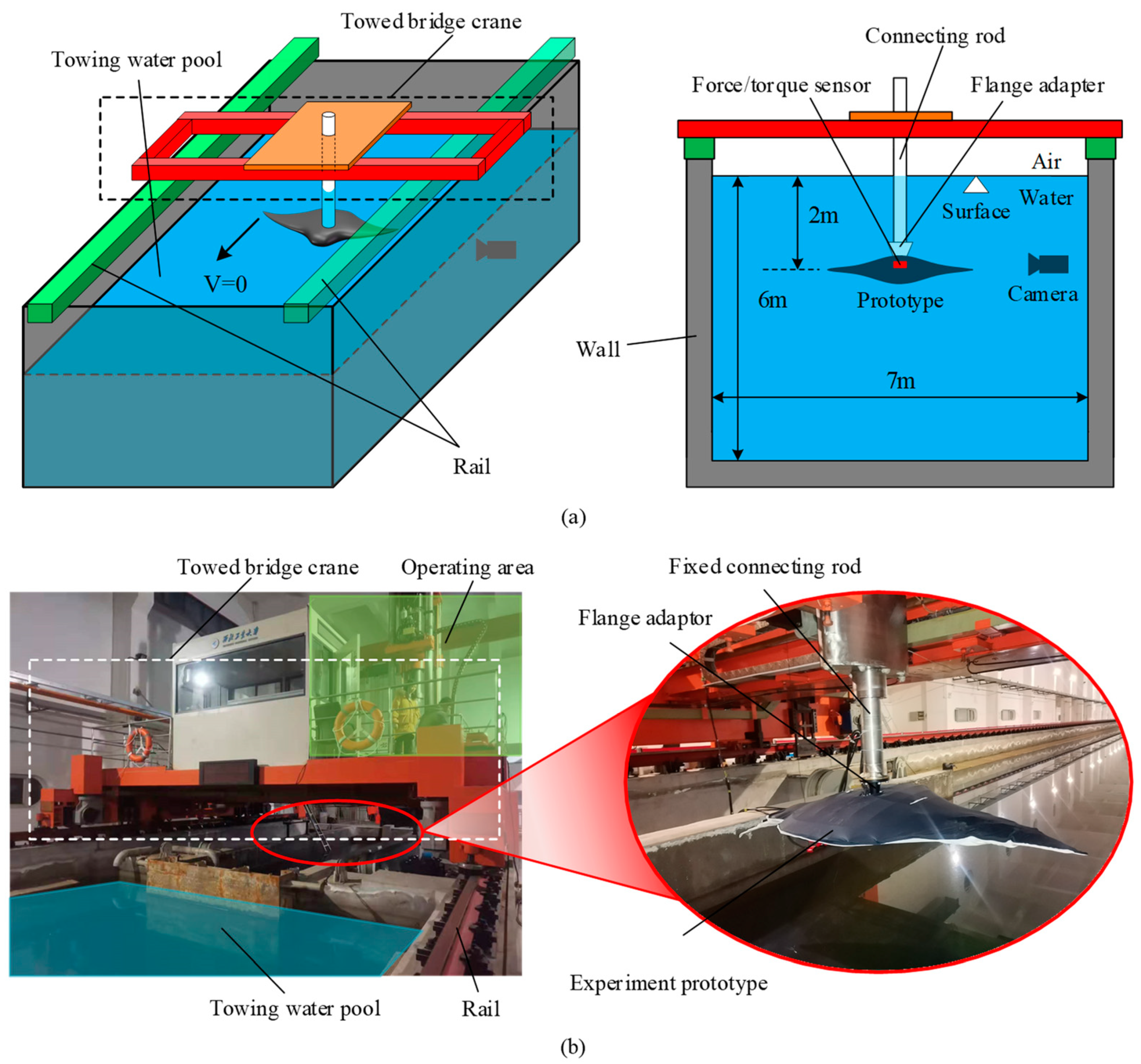
3.1. The Experimental Settings

As shown in Figure 5a, an experimental prototype was built to observe the hydrodynamic performance of the bionic pectoral fin. Transverse and longitudinal braced frames made of polypropylene were used as supports in the middle part of the prototype. Bionic pectoral fins were symmetrically installed across the x b o b z b plane. The experimental prototype was wrapped with a layer of flexible skin made of polyurethane. On one hand, the flexible skin could increase the pectoral fin plate’s effective area to improve the pectoral fin’s propulsion performance. On the other hand, the flexible skin ensures that the experimental prototype has a complete and sealed configuration. The coordinate frame C b coincides with the mass center of the experimental prototype, as shown in Figure 5a, and the installation position of the ATI mini 45 force/torque sensor also coincides with the mass center. The sensing ranges and resolutions can be found in Table 1. The positive direction of the force measured by the sensor was the same as that of the coordinate axis of C b . The positive direction of the torque is shown in Figure 5a, and the anticlockwise direction is defined as the positive torque direction. In summary, the force and torque produced by pectoral fin oscillation are not directly measured but measured based on the comprehensive effect of the force/torque generated by the pectoral fins on both sides of the mass center. Therefore, different hydrodynamic performances can be produced by changing the oscillation parameters of both pectoral fins.
The cable connection and data flow of the experimental prototype are shown in Figure 5b. The system consisted of a power supply, a control board, a force/torque sensor net box, an experimental prototype, and two personal computers (PCs). Among these, PC2 was used to change the oscillating parameters such as the frequency, amplitude, phase difference, and bias of the bionic pectoral fin, while PC1 collected the force/torque data measured by the ATI mini 45 force/torque sensor through the net box. The output voltage of the power supply was 24 V. The central pattern generator (CPG) method was used as the control strategy to drive the bionic pectoral fin to oscillate [29]. Figure 5c shows the diagram of the CPG. The required input parameters for us to enter are only A m i , f , Δ φ l e f t , Δ φ r i g h t , and δ i , then the CPG can generate continuous motion according to the motion equation (refer to (1)), without human intervention. The phase difference Δ φ l e f t is determined by phases φ 1 and φ 2 . δ 1 and δ 2 are the bias angles away from the x b o b y b plane. When the relationship of δ 1 and δ 2 shown in Figure 5c is the same as that between A m 1 and A m 2 , as shown in Figure 3c, the y l o l z l plane is parallel to the y b o b z b plane, and the x l o l y l plane, which is overlapped with the pectoral fin plate, is vertical to the y b o b z b plane. At this point, the angle between o l y l and o b y b is defined as δ l e f t , representing the angle between the oscillating symmetry plane and the x b o b y b plane.
The experiment was carried out in a towing water pool. As shown in Figure 6a, the rail and towed bridge crane were installed above the pool. In this research, the experimental prototype was installed on the connecting rod through a flange adaptor, and the velocity of the towed bridge crane was 0. The experimental prototype was placed 2 m below the water surface to eliminate the interference of the water surface fluctuation on the experimental results. The distance between the fin tip of the experimental prototype and the wall was 2.5 m. An underwater camera was used to capture the bionic pectoral fin’s oscillating movement form. The actual experiment scene is shown in Figure 6b. The data collection and parameter adjustment of the experimental prototype were carried out in the operating area. The detailed parameters of the experimental system including the towing water pool and the prototype are shown in Table 2.
The MPF mode fish can achieve different swimming performances through the oscillating pectoral fins. In this research, in addition to paying attention to the thrust produced by oscillation, methods to achieve different motion swimming effects such as pitching and turning, were also considered. By changing the input parameters of Figure 5c, the different oscillation forms could be achieved. For example, when the input parameter A l e f t A r i g h t , it means that the amplitude of the left fin and right fin is different. When the input parameter δ i 0 satisfies the formula in Figure 5c, it means that there is an initial bias between the pectoral fin and the x b o b y b plane. When the input parameter δ i 0 does not satisfy the formula in Figure 5c, the pitch angle of pectoral fin β 0 . All input parameters will be applied to Equation (1) to calculate the rotation angle of motors; only a few examples are listed here, and the specific parameter changes are shown in Figure 7. There are six different kinds of oscillation forms studied in this research, which were labeled as Cases A to F. In case A, the flapping frequency of the pectoral fins varied between 0.17 Hz and 0.51 Hz, the amplitude varied between 20° and 40°, and the phase difference varied between −30° and 30°. The specific parameters for case A are shown in Table 3. Cases B to F are defined as asymmetric oscillations, where there are different forces/torques produced by the left and right pectoral fins. In Cases B and C, the zero flapping position coincided with the x b o b y b plane. In Cases D to F, the zero flapping position coincided with the red dotted lines. Keeping f = 0.34   Hz and A m = 35 ° unless otherwise stated, the specific parameters of Cases B to F are shown in Table 4.

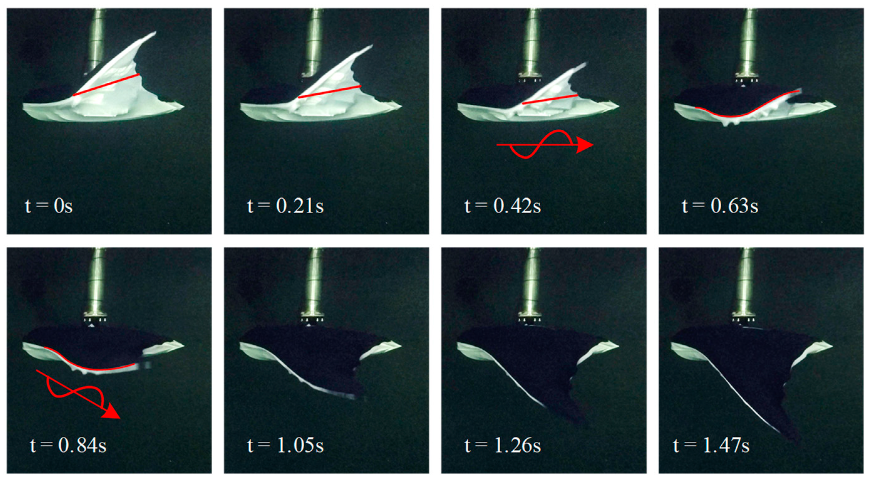
3.2. The Experimental Results

Figure 8 shows the morphological changes in the bionic pectoral fin during downstroke oscillation. It can be clearly observed that there was a wave generated at the root of the pectoral fin, and the wave simultaneously transmits along the spanwise and chordwise directions. This indicates that the bionic pectoral fin proposed in this research can realize oscillation movement similar to that of real MPF mode fishes.
In Case A, the pectoral fins oscillate symmetrically about the x b o b y b plane. There is a noticeable difference in the force/torque produced by the oscillating pectoral fins when changing the combination of the three parameters. In this research, ten consecutive stable oscillating periods were selected to calculate the average value of trust. The purpose of this selection was to ensure that the measured values of the ten selected periods were reliable. Because the original data collected by the sensor formed a sawtooth shape, the original data were smoothed to obtain the smoothed data, as shown in Figure 9a. The average thrust error before and after smoothing was 0.019%, which means that the effect of smoothing in this research can be ignored. The smoothed thrust, lift, and pitching moment curves are shown in Figure 9. The period of the lift and pitching moment was twice that of the thrust. There were two peaks in one period of thrust, and this phenomenon indicates that the pectoral fin can generate two thrusts in one oscillation period. Moreover, the lift and pitching moments only had one peak, and the peak occurred when the pectoral fin plane oscillated close to the x b o b y b plane. The thrust curve was mainly distributed above 0, while the lift and pitch curves were distributed almost symmetrically on both sides of 0.
Figure 10a shows the relationships between the average thrust and the amplitude, phase difference, and frequency. With an increasing amplitude and phase difference, the average thrust gradually grows, and the growth rate caused by the amplitude change was more significant than that caused by the phase difference change. This indicates that when the thrust needs to be increased, the best approach is to increase the amplitude rather than the phase difference. Regardless of the phase difference, the average thrust is always greater than zero. The bionic pectoral fin could not generate reverse thrust. When the oscillating frequency is low, the average thrust increases with the increase in frequency. However, a particular situation occurs when the frequencies were 0.43 Hz and 0.51 Hz. The average thrust on the left side of Figure 10a was almost the same at frequencies of 0.43 Hz and 0.51 Hz, while the average thrust on the right side of Figure 10a at 0.43 Hz was more significant than that at 0.51 Hz. This phenomenon indicates that the average thrust produced does not change linearly with increasing oscillating frequency. This kind of scenario also occurs in the maximum lift and maximum pitching moment. Figure 10b,c show the maximum lift and pitching moment, respectively. Because the average lift and pitching moment are distributed near zero, the range of change is minor. In comparison, the changes in the maximum lift and pitching moment are more prominent. The frequency influences on the average thrust, the maximum lift, and the maximum pitching moment indicate that this phenomenon may be related to the natural frequency. A study [30] showed that when the forcing frequency and natural frequency were the same, the average thrust and flapping efficiency of a flexible heaving wing were greatly enhanced. Many other factors that have not been considered in this research could affect the natural frequency of the bionic pectoral fin such as the pectoral fin rigidity and the flexibility distribution. The relationship between hydrodynamic performance and the above factors is a complicated question and warrants further detailed research in future work.
Unlike Case A, Cases B to F generated additional torque while generating thrust. For ease of description, the equivalent point was defined in this research, where the equivalent point of the pitching moment is shown in Figure 11. It is worth noting that the equivalent point is the projection of the real action point on the plane of the coordinate frame. For example, it can be considered that the average pitching moment T y ¯ is caused by the average thrust F x ¯ and average lift F z ¯ . F x ¯ , F z ¯ , and T y ¯ are obtained from the smoothed data, and the expressions of l and γ are shown in Figure 11. The position of the equivalent point in polar coordinates can be obtained. The equivalent point of the yawing and rolling moment can also be defined in this way. The original point of the polar coordinates in Figure 11 coincides with that of C b , where the counterclockwise direction is defined as the positive direction. By comparing the position changes of equivalent points in polar coordinates, the hydrodynamic performances of the bionic pectoral fins can be analyzed.
In Cases B and C, the hydrodynamic performances of the pectoral fins on each side were significantly different. Therefore, the yawing moment generated by the bionic pectoral fin was mainly analyzed. There were apparent differences in the hydrodynamic performances and the positions of the equivalent points between Cases B and C. As shown in Figure 12, both yawing moments were negative, indicating that the prototype tended to turn right. The change rates of F x ¯ , F y ¯ , and T z ¯ in Case B were more evident than those in Case C, but the significant yawing moment change rate of Case B was obtained at the expense of thrust. The same situation occurred for the distance between the equivalent point and the original point. The experimental results indicate that the hydrodynamic performance was more sensitive to the change in the oscillating amplitude than that in the phase difference, which is consistent with the results in Case A.
In Case D, the oscillating zero position changed, and the angles of the initial zero positions δ l e f t and δ r i g h t were the opposite to each other, meaning that the directions of the hydrodynamic forces such as the lift and literal force generated by the oscillating pectoral fin also changed. The prototype tended to roll left and the rolling moment was mainly analyzed, as shown in Figure 13. With the increase in the absolute value of δ l e f t , the average lift and average rolling moment increased gradually. The equivalent point of Case D gradually moved away from the original point.
In Cases E and F, the results are shown in Figure 14. The zero flapping positions of the pectoral fins on both sides were symmetrical about the x b o b z b plane, the forces generated by the pectoral fins on both sides were the same, and the pitching moment was mainly analyzed. There was little difference between the two cases according to the value and variation trends of the force and torque. The lift generated by Case E was negative, and that generated by Case F was also positive; this also led to different variation laws in the distribution of the pitching moment equivalent points. In practice, this paper holds that the reason for the negative lift in Case E is that the oscillation of the pectoral fin is basically above the x b o b y b plane, resulting in a larger effective upstream area of the lift than that in Case F. The oscillating part below the x b o b y b plane accounted for a small proportion and the speed was low, so it could not produce enough forward lift. In Case F, from the angle of the pitch maneuverability, the same effect could be achieved.
The above results and analysis verified that the bionic pectoral fin proposed in this research is effective and can be utilized as a propeller for bionic underwater robots. The bionic pectoral fin can be used to improve the maneuverability of integrated sliding and flapping underwater robot fish. For underwater vehicles, the improvement in mobility can improve their operation abilities in complex marine environments.
In this research, many parameters that would affect the hydrodynamic performance of the bionic pectoral fin were not considered such as the stiffness of the pectoral fin [31] and the shape of the pectoral fin. These parameters will have an impact on the propulsion effects of the pectoral fins and need to be further studied.

4. Conclusions

In this paper, a novel bionic pectoral fin was proposed, and the effects of the oscillation parameters on the bionic pectoral fin hydrodynamic performance were studied experimentally. The purpose of this study was to better understand the MPF mode swimming principle and provide a basis for developing bionic robot fish. A wide range of motion parameters such as the amplitude, frequency, phase difference, and initial bias were considered.
First, a bionic pectoral fin mechanism that can realize active control and passive deformation was designed according to the natural pectoral fin skeleton structure and oscillation morphology of an underwater creature. The motion analysis showed that the 2-DOF bionic pectoral fin could realize the generation and transmission of waves on the pectoral fin. The motion trajectory of the fin tip in space presents an “8”-shaped spatial trajectory that truly simulates the movement form of a biological pectoral fin. Second, the hydrodynamic performance of the bionic pectoral fin was experimentally studied in a water pool, especially the influence of asymmetric oscillation on hydrodynamic performance. The variations in the thrust, lift, pitching moment, rolling moment, and yawing moment under different oscillation parameters were obtained and analyzed. The results indicate that the bionic vehicle could change the oscillation parameters to increase thrust, lift, or maneuverability, depending upon the situation.
In ongoing and future work, a self-powered underwater robot fish will be developed to concentrate on studying the free-swimming speed and maneuverability. In addition, the pectoral fin’s flexibility and distribution will be explored to enhance the ability of the robot fish to operate in real-world underwater environments. Combined with the main structure of traditional gliders, a brand new flap-and-glide bionic underwater vehicle could be achieved, which could be used in marine environmental investigation and protection, etc.

Supplementary Materials

The following supporting information can be downloaded at: https://www.mdpi.com/article/10.3390/jmse10020289/s1, Figure S1: MPF model fish free swimming frame sequence. (a) Eagle ray forward swimming, shot at Sanya Atlantis Aquarium. (b) Cownose ray turn swimming, shot at Sanya Atlantis Aquarium. (c) Cownose ray pitch swimming, shot at Beijing Aquarium. Adapted from the Ph.D. dissertation of Cao Yong (2015, Beihang University); Figure S2: The complete flap-and-glide bionic underwater vehicle.

Author Contributions

Supervision, Y.C. (Yong Cao), Y.C. (Yonghui Cao), G.P. and Q.H.; Writing—original draft, C.X.; Writing—review & editing, C.X. and Y.C. (Yong Cao). All authors have read and agreed to the published version of the manuscript.

Funding

This research was funded by National Natural Science Foundation of China: 51879200; National Natural Science Foundation of China: 52001260; National Key Research and Development Program: 2020YFB1313200.

Institutional Review Board Statement

Not applicable.

Informed Consent Statement

Not applicable.

Data Availability Statement

Not applicable.

Conflicts of Interest

The authors declare no conflict of interest.

References

  1. Triantafyllou, M.S.; Triantafyllou, G.S. An efficient swimming machine. Sci. Am. 1995, 272, 64–74. [Google Scholar] [CrossRef]
  2. Altringham, J.D.; Ellerby, D.J. Fish swimming: Patterns in muscle function. J. Exp. Biol. 1999, 202, 3397–3403. [Google Scholar] [CrossRef]
  3. Blake, R.W. Swimming in the electric eels and knifefishes. Can. J. Zool. 1983, 61, 1432–1441. [Google Scholar] [CrossRef]
  4. Lauder, G.V.; Drucker, E.G. Forces, fishes, and fluids: Hydrodynamic mechanisms of aquatic locomotion. News Physiol. Sci. 2002, 17, 235–240. [Google Scholar] [CrossRef] [PubMed] [Green Version]
  5. Maciver, M.; Fontaine, E.; Burdick, J. Designing Future Underwater Vehicles: Principles and Mechanisms of the Weakly Electric Fish. IEEE J. Ocean. Eng. 2004, 29, 651–659. [Google Scholar] [CrossRef]
  6. Webb, P.W. Form and Function in Fish Swimming. Sci. Am. 1984, 251, 72–82. [Google Scholar] [CrossRef]
  7. Wang, T.M.; Yang, X.B.; Liang, J.H. A survey on bionic autonomous underwater vehicles propelled by median and/or paired fin mode. Robot 2013, 35, 352–363. [Google Scholar] [CrossRef]
  8. Xie, F.; Zuo, Q.; Chen, Q.; Fang, H.; He, K.; Du, R.; Zhong, Y.; Li, Z. Designs of the biomimetic robotic fishes performing body and/or caudal fin (BCF) swimming locomotion: A Review. J. Intell. Robot. Syst. 2021, 102, 1–19. [Google Scholar] [CrossRef]
  9. Scaradozzi, D.; Palmieri, G.; Costa, D.; Pinelli, A. BCF swimming locomotion for autonomous underwater robots: A review and a novel solution to improve control and efficiency. Ocean Eng. 2017, 130, 437–453. [Google Scholar] [CrossRef]
  10. Yu, J.; Wu, Z.; Su, Z.; Wang, T.; Qi, S. Motion Control Strategies for a Repetitive Leaping Robotic Dolphin. IEEE/ASME Trans. Mechatron. 2019, 24, 913–923. [Google Scholar] [CrossRef]
  11. Katzschmann, R.K.; Del Preto, J.; Mac Curdy, R.; Rus, D. Exploration of underwater life with an acoustically controlled soft robotic fish. Sci. Robot. 2018, 3, 3449. [Google Scholar] [CrossRef] [Green Version]
  12. Russo, R.S.; Blemker, S.S.; Fish, F.E.; Bart-Smith, H. Biomechanical model of batoid (skates and rays) pectoral fins predicts the influence of skeletal structure on fin kinematics: Implications for bio-inspired design. Bioinspir. Biomim. 2015, 10, 046002. [Google Scholar] [CrossRef] [Green Version]
  13. Sfakiotakis, M.; Lane, D.M.; Davies, J.B.C. Review of fish swimming modes for aquatic locomotion. IEEE J. Ocean. Eng. 1999, 24, 237–252. [Google Scholar] [CrossRef] [Green Version]
  14. Fish, F.E.; Schreiber, C.M.; Moored, K.W.; Liu, G.; Dong, H.; Bart-Smith, H. Hydrodynamic performance of aquatic flapping: Efficiency of underwater flight in the manta. Aerospace 2016, 3, 20. [Google Scholar] [CrossRef] [Green Version]
  15. Schaefer, J.T.; Summers, A.P. Batoid wing skeletal structure: Novel morphologies, mechanical implications, and phylogenetic patterns. J. Morphol. 2005, 264, 298–313. [Google Scholar] [CrossRef] [PubMed]
  16. Heine, C. Mechanics of Flapping Fin Locomotion in the Cownose Ray, Rhinoptera bonasus (Elasmobranchii: Myliobatidae). Ph.D. Thesis, Department of Zoology, Duke University, Durham, NC, USA, 1992. [Google Scholar]
  17. Rosenberger, L.J. Pectoral fin locomotion in batoid fishes: Undulation versus oscillation. J. Exp. Biol. 2001, 204, 379–394. [Google Scholar] [CrossRef] [PubMed]
  18. Dewey, P.A.; Carriou, A.; Smits, A.J. On the relationship between efficiency and wake structure of a batoid-inspired oscillating fin. J. Fluid Mech. 2011, 691, 245–266. [Google Scholar] [CrossRef]
  19. Liu, G.; Ren, Y.; Zhu, J.; Bart-Smith, H.; Dong, H. Thrust producing mechanisms in ray-inspired underwater vehicle propulsion. Theor. Appl. Mech. Lett. 2015, 5, 54–57. [Google Scholar] [CrossRef] [Green Version]
  20. Davis, H. Mechanization of Rajiform Swimming Motion: The Making of Robo-Ray; University of British Columbia: Vancouver, BC, Canada, 2002; Available online: https://www.researchgate.net/publication/266457567 (accessed on 14 January 2002).
  21. Robot Fish; Springer Tracts in Mechanical Engineering; Springer: Berlin/Heidelberg, Germany, 2015; pp. 219–253. [CrossRef]
  22. Chen, Z.; Um, T.I.; Zhu, J.; Bart-Smith, H. Bio-Inspired Robotic Cownose Ray Propelled by Electroactive Polymer Pectoral Fin. In Proceedings of the ASME 2011 International Mechanical Engineering Congress and Exposition, Denver, CO, USA, 11–17 November 2011; pp. 817–824. [Google Scholar] [CrossRef] [Green Version]
  23. Li, G.; Chen, X.; Zhou, F.; Liang, Y.; Xiao, Y.; Cao, X.; Zhang, Z.; Zhang, M.; Wu, B.; Yin, S.; et al. Self-powered soft robot in the Mariana Trench. Nature 2021, 591, 66–71. [Google Scholar] [CrossRef]
  24. Li, T.; Li, G.; Liang, Y.; Cheng, T.; Dai, J.; Yang, X.; Liu, B.; Zeng, Z.; Huang, Z.; Luo, Y.; et al. Fast-moving soft electronic fish. Sci. Adv. 2017, 3, e1602045. [Google Scholar] [CrossRef] [Green Version]
  25. Meng, Y.; Wu, Z.; Dong, H.; Wang, J.; Yu, J. Toward a Novel Robotic Manta with Unique Pectoral Fins. IEEE Trans. Syst. Man, Cybern. Syst. 2020, 1–11. [Google Scholar] [CrossRef]
  26. Cai, Y.; Chen, L.; Bi, S.; Li, G.; Zhang, H. Bionic Flapping Pectoral Fin with Controllable Spatial Deformation. J. Bionic Eng. 2019, 16, 916–930. [Google Scholar] [CrossRef]
  27. Animal Locomotion; Springer: Berlin/Heidelberg, Germany, 2010; pp. 3–15. [CrossRef]
  28. Cao, Y. Applying CPG to Study Manta Rotofish. Ph.D. Thesis, School of Mechanical Engineering and Automation, Beihang University, Beijing, China, 2015. [Google Scholar]
  29. Cao, Y.; Lu, Y.; Cai, Y.; Bi, S.; Pan, G. CPG-fuzzy-based control of a cownose-ray-like fish robot. Ind. Robot. Int. J. Robot. Res. Appl. 2019, 46, 779–791. [Google Scholar] [CrossRef]
  30. Michelin, S.; Llewellyn Smith, S.G. Resonance and propulsion performance of a heaving flexible wing. Phys. Fluids 2009, 21, 071902. [Google Scholar] [CrossRef] [Green Version]
  31. Aiello, B.R.; Hardy, A.R.; Cherian, C.; Olsen, A.M.; Ahn, S.E.; Hale, M.E.; Westneat, M.W. The relationship between pectoral fin ray stiffness and swimming behavior in Labridae: Insights into design, performance, and ecology. J. Exp. Biol. 2018, 221, jeb163360. [Google Scholar] [CrossRef] [PubMed] [Green Version]
Figure 1. Coordinate frames of the rays.
Jmse 10 00289 g001
Figure 2. Mechanical design of the pectoral fin. (a) Calcification of the pectoral fin skeleton, adapted from the research article of Justin T. Schaefer (2005, Wiley) [15]. Red areas indicate calcification, and blue areas indicate cartilage. (b) Spatial linkage mechanism. (c) Fin plate with uniform thickness. (d) The 2-DOF bionic pectoral fin.
Jmse 10 00289 g002
Figure 3. Geometric relationship of the bionic pectoral fin mechanism. (a) Schematic diagram of bionic pectoral fins. (b) Geometric relationship between the driving components without compensation. (c) Geometric relationship between the driving components after compensation.
Jmse 10 00289 g003
Figure 4. Motion analysis results of the bionic pectoral fin. (a) The curves of θ and β changes over time. (b) The curves of ω θ and ω β changes over time. (c) The curves of r 1 and V A changes over time. (d) The spatial trajectories of the left pectoral fin coordinate origin o l .
Jmse 10 00289 g004
Figure 5. Composition and configuration of the experimental system. (a) Mechanical composition of the experimental prototype. (b) Cable connection and data flow of the experimental prototype. (c) Diagram of the CPG control strategy Adapted from the Ph.D. dissertation of Cao Yong (2015, Beihang University) [28] and definition of the pectoral fin bias.
Jmse 10 00289 g005
Figure 6. The composition of the experimental system. (a) The composition of the towing water pool and the installation diagram of the experimental prototype. (b) The actual experiment scene.
Jmse 10 00289 g006
Figure 7. Diagram of the six different oscillation cases. Case (A): The pectoral fins oscillate symmetrically about the plane x b o b y b , where A m , l e f t = A m , r i g h t ; f l e f t = f r i g h t ; Δ φ l e f t = Δ φ r i g h t ; and δ l e f t = δ r i g h t = 0 . Case (B): The pectoral fins oscillate symmetrically about the plane x b o b y b , but the amplitudes of the left and right pectoral fins are different, where A m , l e f t A m , r i g h t ; f l e f t = f r i g h t = 0.34   Hz ; Δ φ l e f t = Δ φ r i g h t = 10 ° ; and δ l e f t = δ r i g h t = 0 . Case (C): The pectoral fins oscillate symmetrically about the plane x b o b y b , but the phase difference between the left and right pectoral fins is different, where A m , l e f t = A m , r i g h t = 35 ° ; f l e f t = f r i g h t = 0.34   Hz ; Δ φ l e f t Δ φ r i g h t ; and δ l e f t = δ r i g h t = 0 . Case (D): The pectoral fins oscillate symmetrically about the red initial position, where A m , l e f t = A m , r i g h t = 35 ° ; f l e f t = f r i g h t = 0.34   Hz ; Δ φ l e f t = Δ φ r i g h t = 10 ° ; and δ l e f t = δ r i g h t . Case (E): The pectoral fins oscillate symmetrically about the red initial position, where A m , l e f t = A m , r i g h t = 35 ° ; f l e f t = f r i g h t = 0.34   Hz ; Δ φ l e f t = Δ φ r i g h t = 10 ° ; and δ l e f t = δ r i g h t 0 . Case (F): The pectoral fins oscillate symmetrically about the red initial position, where A m , l e f t = A m , r i g h t = 35 ° ; f l e f t = f r i g h t = 0.34   Hz ; Δ φ l e f t = Δ φ r i g h t = 10 ° ; and δ l e f t = δ r i g h t = 0 ; β 0 .
Jmse 10 00289 g007
Figure 8. Morphological changes in the pectoral fin during the downstroke ( A m = 35 ° , f = 0.34   Hz , and Δ φ = 3 0 ° ).
Jmse 10 00289 g008
Figure 9. Data smoothing and comparison. (a) Comparison of the original data and smoothed data. (b) Thrust variation with time ( f = 0.34   Hz , Δ φ = 1 0 ° ). (c) Lift variation with time ( f = 0.34   Hz , Δ φ = 1 0 ° ). (d) Pitching moment variation with time ( f = 0.34   Hz , Δ φ = 1 0 ° ).
Jmse 10 00289 g009
Figure 10. Influences of different oscillation parameters on the hydrodynamic performance. (a) The influence on average thrust. (b) The influence on the maximum lift. (c) The influence on the maximum pitching moment.
Jmse 10 00289 g010
Figure 11. The definition of the equivalent point.
Jmse 10 00289 g011
Figure 12. Hydrodynamic performance and equivalent point variation in turning torque. (a) Experimental results of Case B. (b) Experiment results of Case C.
Jmse 10 00289 g012
Figure 13. Hydrodynamic performance and equivalent point variation in Case D.
Jmse 10 00289 g013
Figure 14. Hydrodynamic performance and equivalent point variation in pitching torque. (a) Experimental results of Case E. (b) Experimental results of Case F.
Jmse 10 00289 g014
Table 1. Ranges and resolutions of the ATI mini 45 force/torque sensor.
Force/TorqueSensing RangesResolutionsMeasuring Accuracy
F x , F y 580 N1/4 N0.043% FR (full-range)
F z 1160 N1/4 N0.022% FR
T x , T y 20 N∗m1/188 N∗m0.026% FR
T z 20 N∗m1/376 N∗m0.013% FR
Table 2. Main technical parameters of the experimental system.
ItemValues
Dimension of towing water pool170 m × 7 m × 6 m
Towing speed0 m/s
Prototype body length1 m
Prototype span length2 m
Prototype weight30 kg
Motor power60 W × 4
Table 3. Pectoral fin oscillating motion parameters for Case A.
ParametersValue
Frequency0.17 Hz0.26 Hz0.34 Hz0.43 Hz0.51 Hz
Amplitude20°25°30°35°40°
Phase difference−30°−20°−10°10°20°30°
Table 4. Pectoral fin oscillating motion parameters for Cases B, C, D, E, and F.
NumberCase BCase CCase DCase ECase F
1 A m , l e f t = 40 ° , A m , r i g h t = 40 ° Δ φ l e f t = 30 ° , Δ φ r i g h t = 25 ° δ l e f t = 0 ° , δ r i g h t = 0 ° δ l e f t = 0 ° , δ r i g h t = 0 ° β = 0 °
2 A m , l e f t = 40 ° , A m , r i g h t = 35 ° Δ φ l e f t = 30 ° , Δ φ r i g h t = 20 ° δ l e f t = 5 ° , δ r i g h t = 5 ° δ l e f t = 5 ° , δ r i g h t = 5 ° β = 3 °
3 A m , l e f t = 40 ° , A m , r i g h t = 30 ° Δ φ l e f t = 30 ° , Δ φ r i g h t = 15 ° δ l e f t = 10 ° , δ r i g h t = 10 ° δ l e f t = 10 ° , δ r i g h t = 10 ° β = 6 °
4 A m , l e f t = 40 ° , A m , r i g h t = 25 ° Δ φ l e f t = 30 ° , Δ φ r i g h t = 10 ° δ l e f t = 15 ° , δ r i g h t = 15 ° δ l e f t = 15 ° , δ r i g h t = 15 ° β = 9 °
5 A m , l e f t = 40 ° , A m , r i g h t = 20 ° Δ φ l e f t = 30 ° , Δ φ r i g h t = 5 ° δ l e f t = 20 ° , δ r i g h t = 20 ° δ l e f t = 20 ° , δ r i g h t = 20 ° β = 12 °
6 Δ φ l e f t = 30 ° , Δ φ r i g h t = 0 °
Publisher’s Note: MDPI stays neutral with regard to jurisdictional claims in published maps and institutional affiliations.

