In recent years, the offshore wind industry in China has developed rapidly. However, as the national subsidy policy for offshore wind power will be abolished after 2021, cost reduction and efficiency increase will be the inevitable trend for the future development of the offshore wind industry in China [
1]. The construction and installation costs of foundations for an offshore wind turbine is a significant fraction of the overall cost (about 20–40%). The selection of a reasonable foundation type for the offshore wind turbine is essential for the parity development of the offshore wind industry. The factors such as water depth, soil conditions, and installed capacity of wind turbine should be fully considered in the foundation selection. The main foundation types for wind turbines include monopiles, jacket foundations, bucket foundations, gravity foundations, high pile cap foundations, and floating foundations [
2,
3,
4,
5]. Among them, the jacket foundations have large stiffness, which can transfer the overturning moment into axial push–pull force to improve the overturning resistance. A bucket foundation is a promising option for its convenient offshore construction [
6,
7,
8]. Bucket jacket foundation (BJF) is a new type of foundation for supporting offshore wind turbine that combines jacket foundation and bucket foundation [
9,
10,
11]. Because of its strong overturning resistance, convenient, and efficient offshore installation, BJF is well suited for deep-sea wind farms, and it has been widely adopted as a current wind turbine foundation with water depth ranging between 20 m to 60 m [
12,
13].
The BJF for offshore wind turbine is subjected to the vertical load from the dead weight of the structure, the horizontal loads from wind, wave, currents and upper loads from the wind turbine, and overturning moments caused by these horizontal loads. It is essential to study the uniaxial capacities of the BJF. In recent years, several experimental studies and finite element analyses have been carried out on the bearing capacity of the BJF. Wang et al. [
14] compared the lateral monotonic and cyclic behavior of monopod and tripod by a series of centrifuge tests in medium sand. It is found that the tripod has higher initial later stiffness than the monopod under monotonic lateral loading. In addition, different from the monopod, the tripod will “self-heal” under the action of lateral cyclic load, which makes it better than the monopod in cumulative rotation and dynamic stiffness. Faizi et al. [
15] designed a hybrid tripod bucket foundation consisting of a conventional tripod bucket and three large circular mats attached to each bucket. A series of model tests were conducted under 1 g in loose sand to study the behavior of the foundation and the influence of bucket spacing on the overturning capacity. Tran et al. [
16] studied the bearing capacities of tripod bucket foundations in medium and dense sands using numerical analyses and proposed bearing capacity equations in consideration of multiple parameters.
The bearing capacity of the bucket is obviously affected by the ratio of the bucket height to the bucket diameter, and this paper designs two kinds of tripod structures, a tripod suction pile jacket foundation (TSPJF), and a tripod bucket jacket foundation (TBJF). TSPJF is a narrow and deep foundation, while TBJF is a wide and shallow foundation. In this paper, the bearing characteristics of the TBJF and TSPJF are studied and compared under monotonic loads in sand using FE analyses.
1. Numerical Simulation
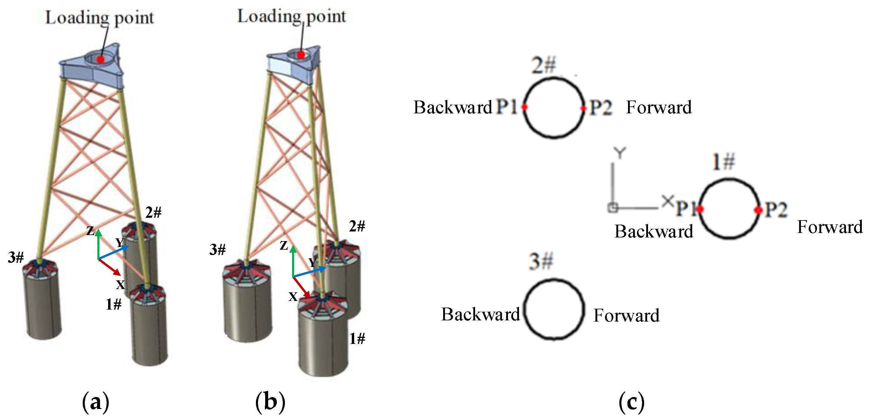
Referring to the loading conditions of a typical 8 MW offshore wind turbine, two kinds of tripod structures, TSPJF and TBJF, are established based on ABAQUS finite element software, as shown in
Figure 1.
Figure 1 also shows the loading point, coordinate system and bucket number, etc. The foundation parameters are shown in
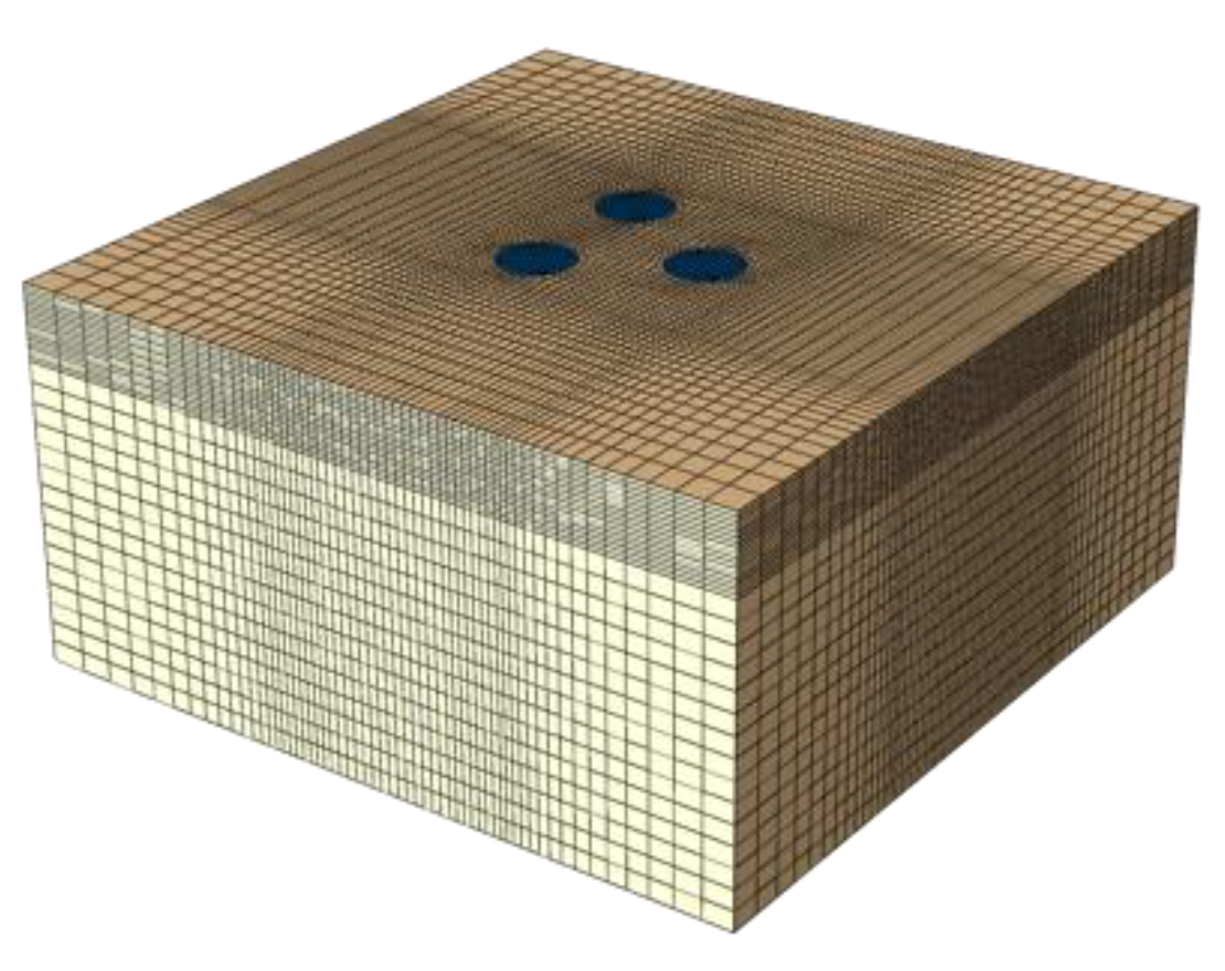
Table 1, and the soil numerical model is shown in
Figure 2. The distances between soil boundaries and the foundation bottom are 4
D in horizontal and 4
H in vertical. The horizontal displacements of soil lateral boundaries are constrained, and the soil bottom boundary is fixed. The soil is modeled by the eight-node linear brick, reduced integration continuum element C3D8R, and follows the Mohr–Coulomb failure criterion. The main parameters of soil are shown in
Table 2. The suction pile and the bucket foundation are modeled by the shell element using steel with a Young’s modulus of 206 GPa and a Poisson’s ratio of 0.3. The interaction between soil and buckets is set as frictional contact in the tangential direction and hard contact in the normal direction, allowing separation of the soil and bucket after contact. The displacement-controlled loading method was applied to obtain the load–displacement curve at the loading point, the center of the flange top surface.
2. Comparison of Bearing Characteristics of the TSPJF and TBJF under Vertical Load
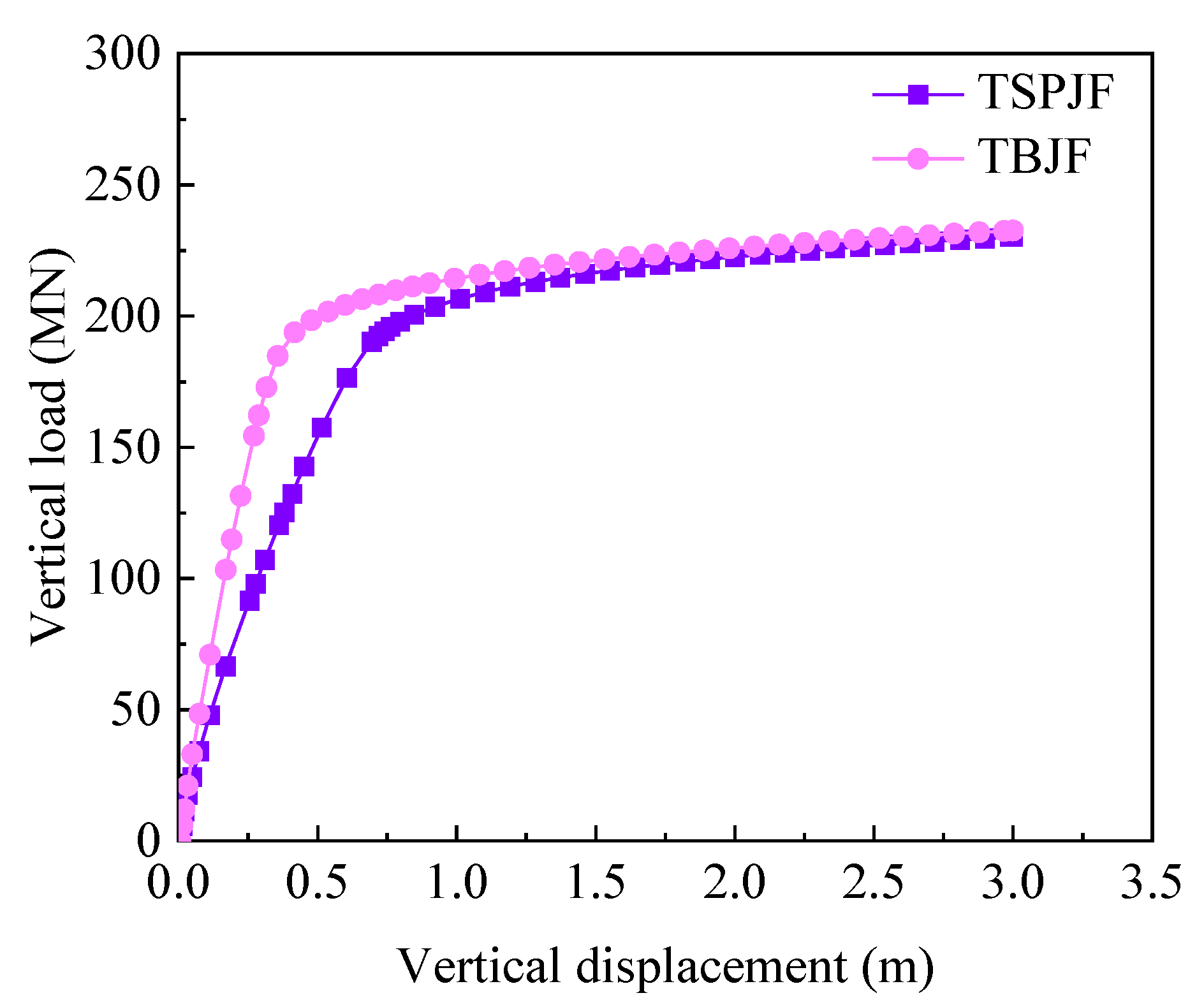
Figure 3 shows the vertical load–displacement curves of the TSPJF and TBJF. Since both load–displacement curves have obvious inflection points, the loads corresponding to the inflection points can be regarded as the ultimate bearing capacity. The vertical bearing capacities of TSPJF and TBJF are 197.94 MN and 193.80 MN, respectively, and the corresponding vertical displacements are 0.72 m and 0.46 m, respectively. The difference between the ultimate bearing capacity of the TSPJF and TBJF is very small, but the corresponding vertical displacement of TBJF is significantly smaller than that of TSPJF.
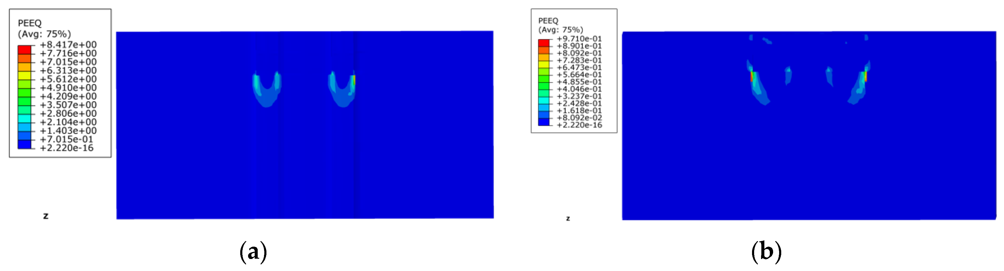
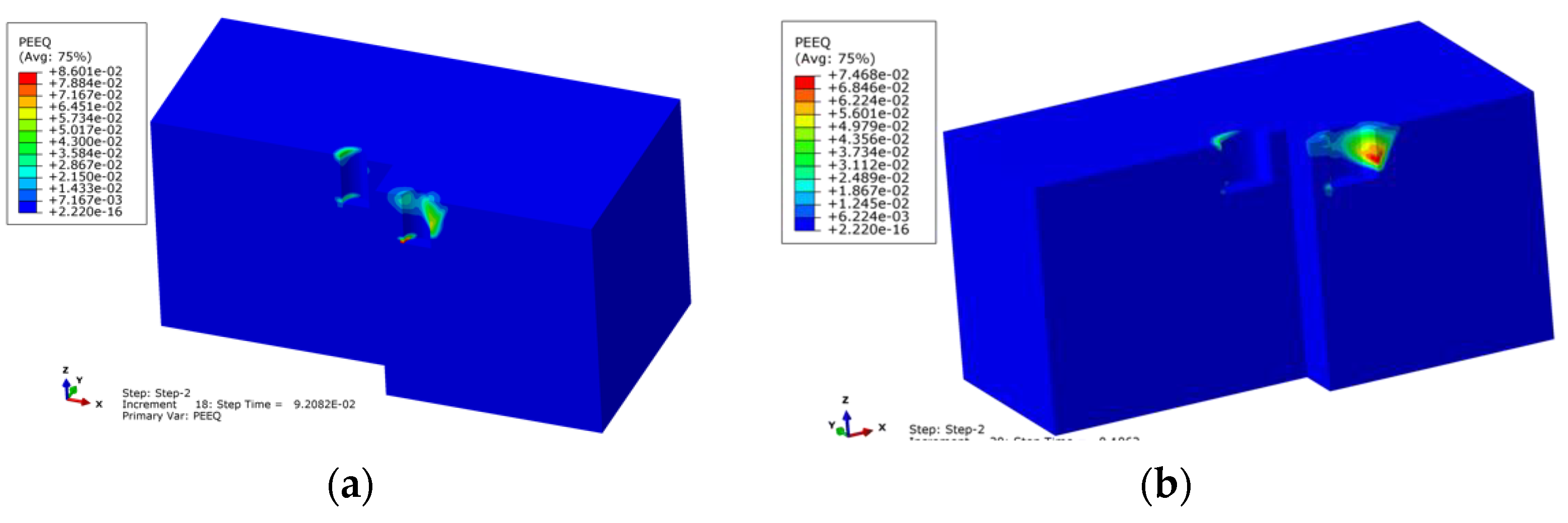
Figure 4 shows soil equivalent plastic strain contours at the 2# and 3# bucket central section for TSPJF and TBJF under the ultimate vertical load. As shown in the figure, the maximum equivalent plastic strain of soil appears at the bucket end for TSPJF, and the plastic failure develops along the depth direction, eventually forming an asymmetrical “V-shaped” plastic failure zone. Similar to the failure mode of TSPJF, the maximum equivalent plastic strain of soil also appears at the bucket end of TBJF and expands along the depth. However, the soil at the end of the bucket of TBJF does not form a continuous “V-shaped” plastic failure zone under the ultimate vertical load.
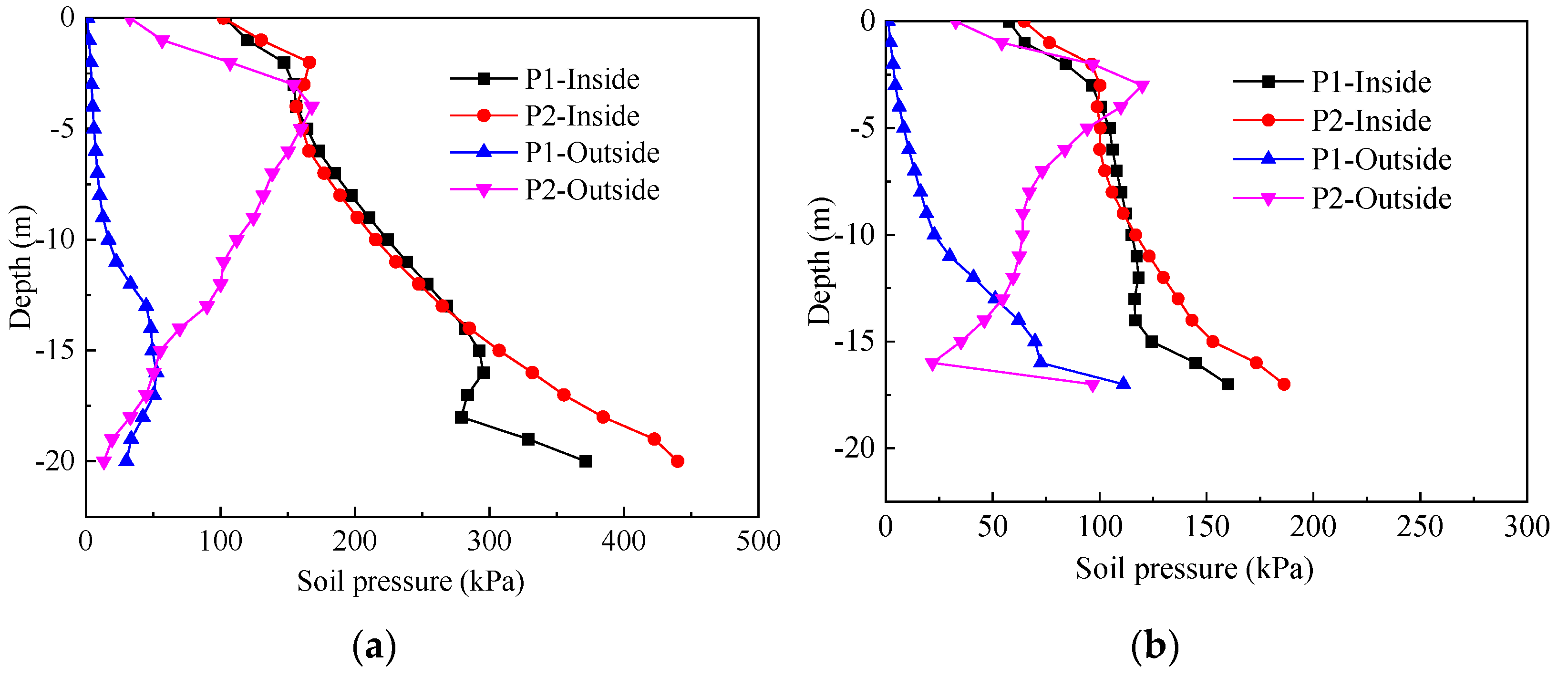
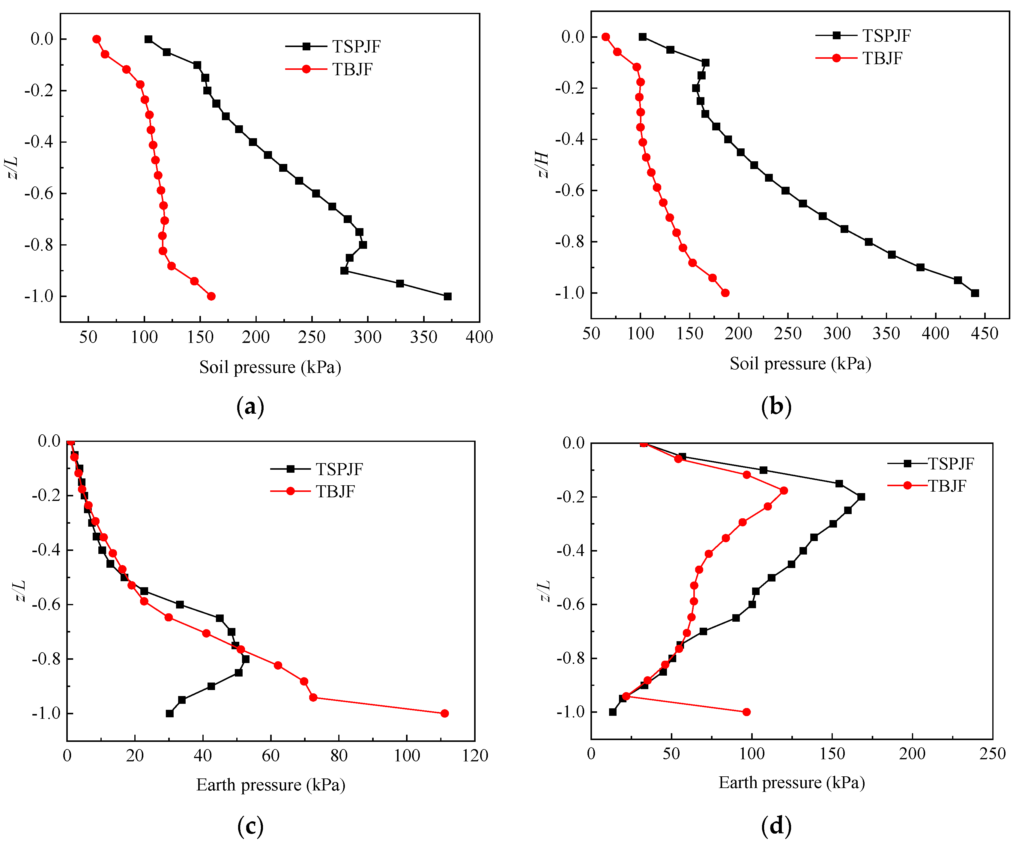
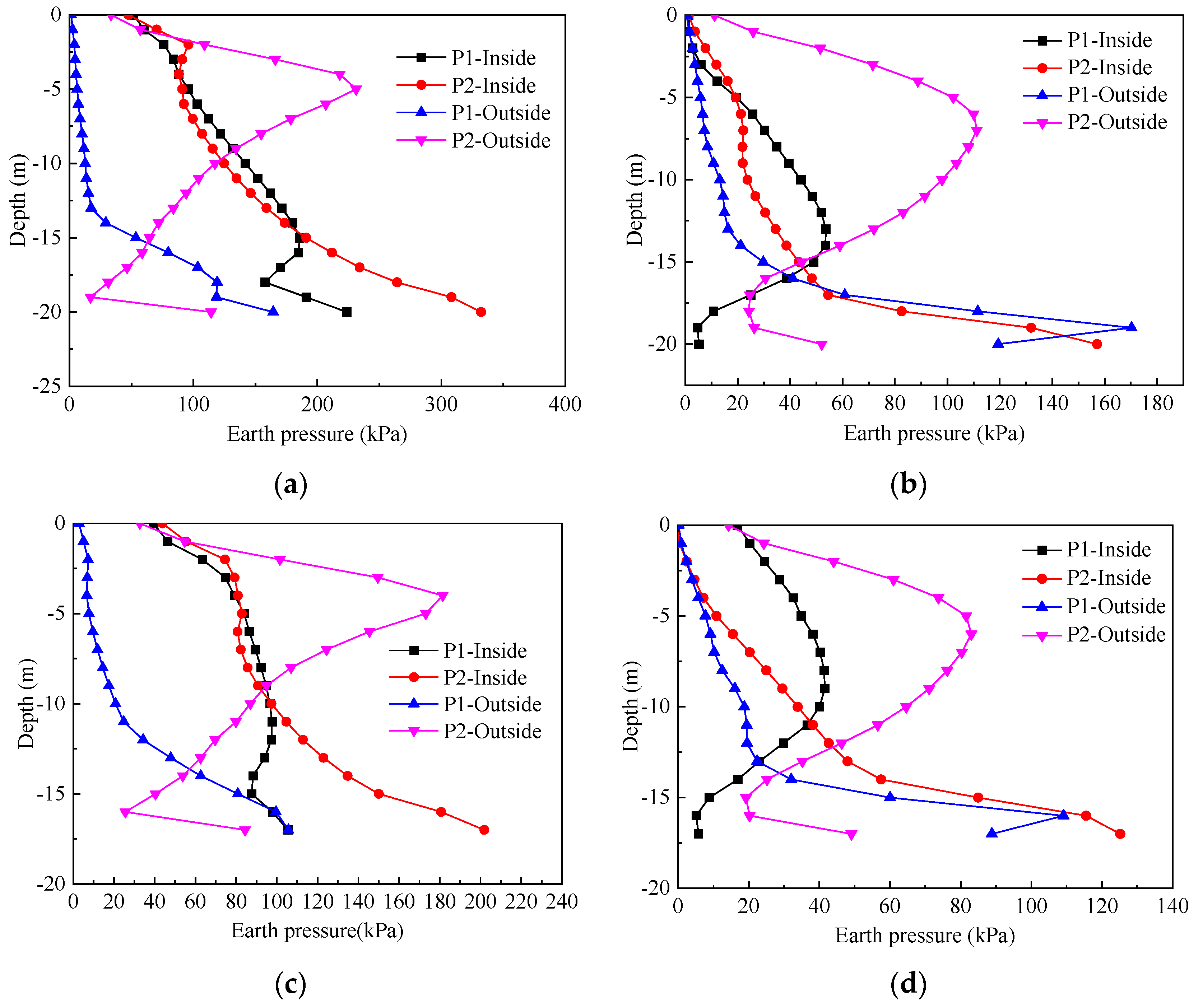
Figure 5 shows the distribution of the earth pressure inside and outside skirt wall at the positions of P1 and P2 of 1# bucket (see
Figure 1c) along the skirt height. The comparison of inside and outside earth pressure at positions P1 and P2 of 1# bucket of the TSPJF and TBJF along the bucket height is displayed in
Figure 6. In general, the earth pressure of the two foundations has similar variation trends. The earth pressure inside the bucket is generally higher than the earth pressure outside the bucket, which is mainly because the soil inside the bucket is constrained by the bucket skirt. For the two foundations, the earth pressure inside the bucket generally increases with the increase in depth, and the increase in TSPJF is more significant. The outside earth pressure of 1# bucket of the TSPJF at P1 and P2 first increases and then decreases with the increase of depth, and the change of outside earth pressure at P1 is relatively small. Different from the TSPJF, the outside earth pressure of 1# bucket of TBJF does not decline at P1, but increases with the increase of depth. The reason may be that the plastic failure zone of the soil at the end of the bucket is different in the ultimate bearing state (see
Figure 4), and the plastic failure of the soil outside the bucket around the end of the bucket of the TSPJF is more serious in the ultimate state.
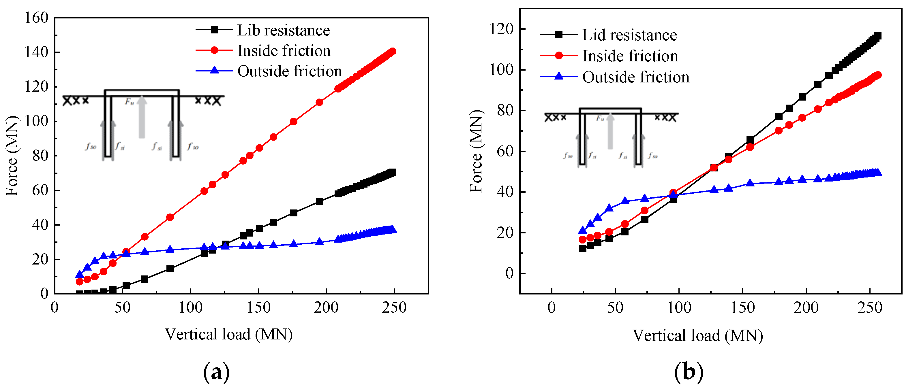
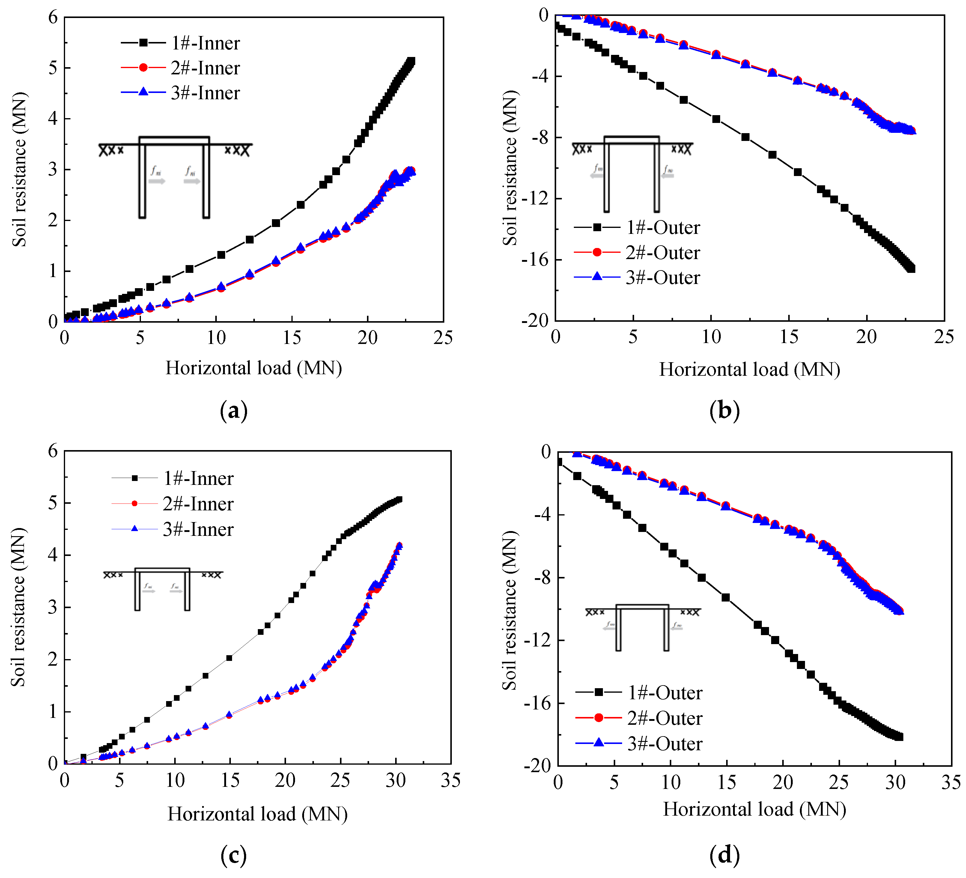
The vertical capacity of the TSPJF and TBJF is composed of four parts: the friction along the inside bucket skirt, the friction along the outside bucket skirt, the vertical resistance on the bucket lid, and the end resistance.
Figure 7 shows the resistance provided by each part of the foundations at different vertical loads. For the two foundations, the vertical load is mainly borne by the inside and outside frictional resistance when the vertical load is small. With the continuous increase of the vertical load, the inside frictional resistance and the vertical resistance from the bucket lid increase significantly, showing a nearly linear increase. The growth rate of the inside frictional resistance of TSPJF is higher than that of the resistance on the bucket lid. Different from TSPJF, the resistance provided by the bucket lid of TBJF increases more than the inside frictional resistance. The outside frictional resistance increase is relatively small, and with the increase of the vertical load, the outside frictional resistance gradually tends to gentle growth.
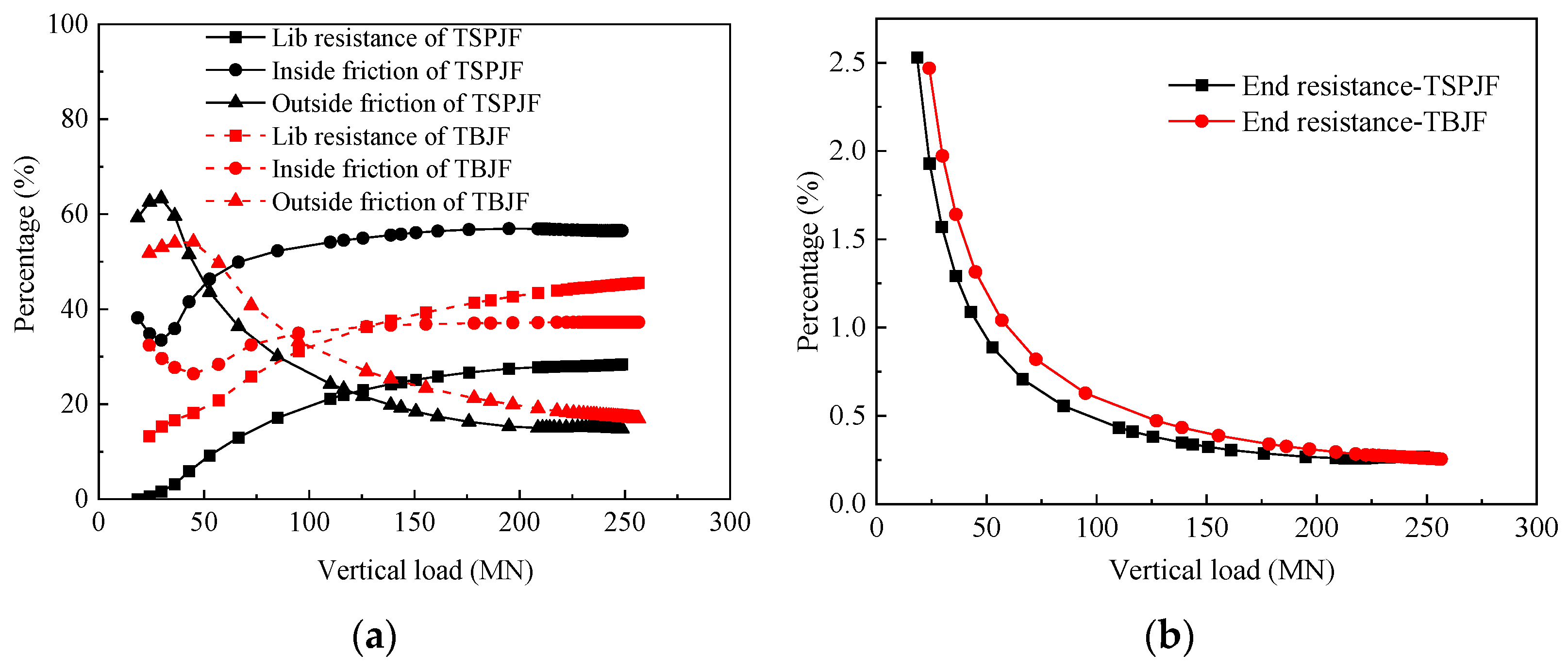
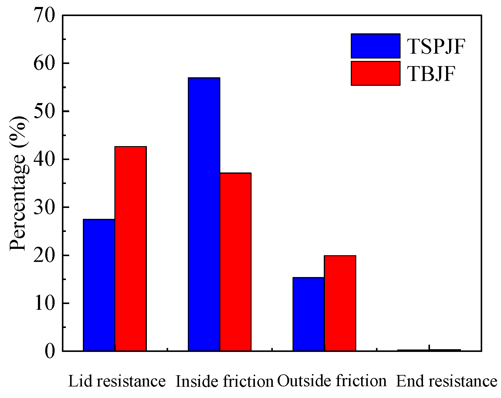
Figure 8 shows the bearing proportion of each part of the foundations at different vertical loads. The proportion of the outside frictional resistance and lid resistance of TBJF is always higher than that of TSPJF, while the proportion of the inside frictional resistance of TBJF is always smaller than that of TSPJF. The bearing proportion of the end resistance of the TSPJF and TBJF is very small, and it decreases with the increase of vertical load. As shown in
Figure 9, in the ultimate vertical bearing state, the proportion of the inside frictional resistance, outside frictional resistance, lid resistance, and end resistance in the total resistance is 57.0%, 15.3%, 27.5%, and 0.3% for TSPJF, and they are 37.1%, 19.9%, 42.7%, and 0.3% for TBJF. Therefore, the vertical ultimate load is mainly borne by the inside frictional resistance for the TSPJF, a narrow and deep bucket foundation, while, for the TBJF, a wide and shallow bucket foundation, it is mainly borne by the bucket lid resistance.
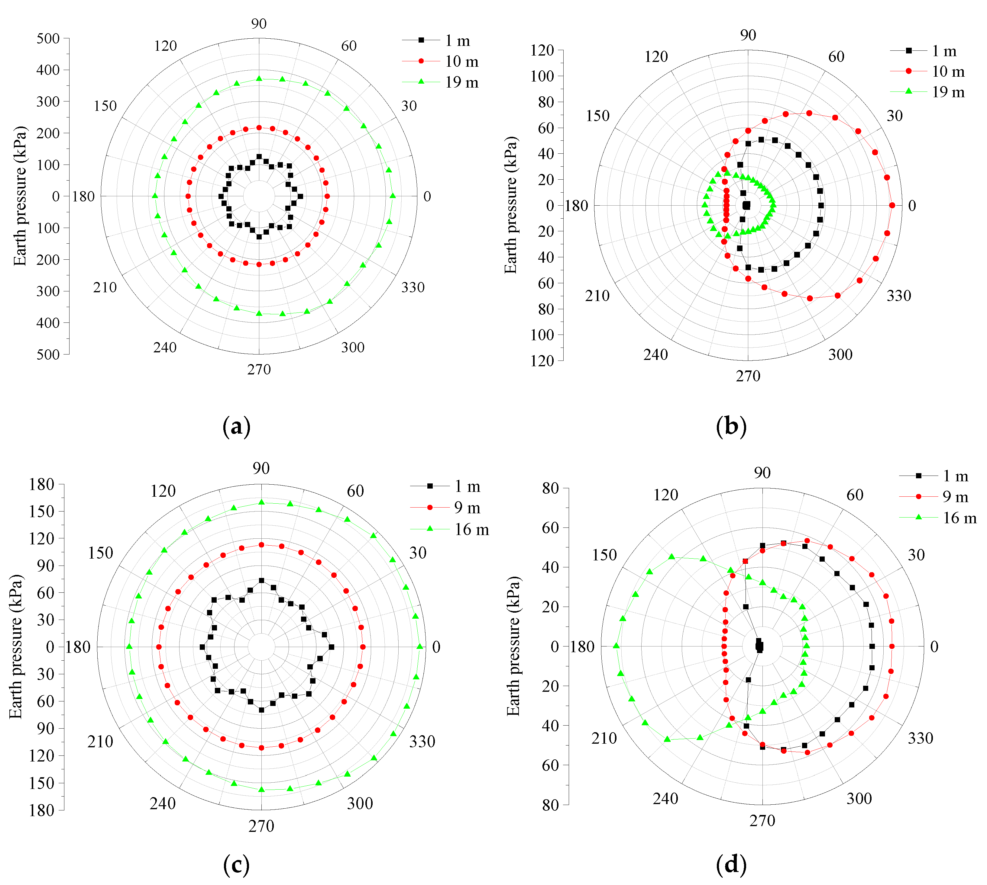
Figure 10 shows the circumferential distribution of earth pressure on the inside and outside skirt of 1# bucket of TSPJF and TBJF at different depths. As shown in
Figure 10a,c, the earth pressure on the inside skirt of TSPJF and TBJF in different directions is almost equal, and it increases with the increase of depth. The circumferential distribution of earth pressure on the outside skirt of 1# bucket of TSPJF is symmetrical along the
x-axis. The maximum and minimum soil pressures at the depths of 1 m and 10 m appear at 0° (positive
x-axis) and 180° (negative
x-axis), while the distribution law of earth pressure at the depth of 19 m, near the bucket end, is exactly the opposite of the former. The circumferential distribution law of earth pressure on the outside skirt of 1# bucket of TBJF is similar to that of the TSPJF.
3. Comparison of Bearing Characteristics of TSPJF and TBJF under Horizontal Load
Two loading directions are considered in the analysis of monotonic horizontal bearing characteristics, including positive x-axis loading and negative x-axis loading.
3.1. Positive x-Axis Loading
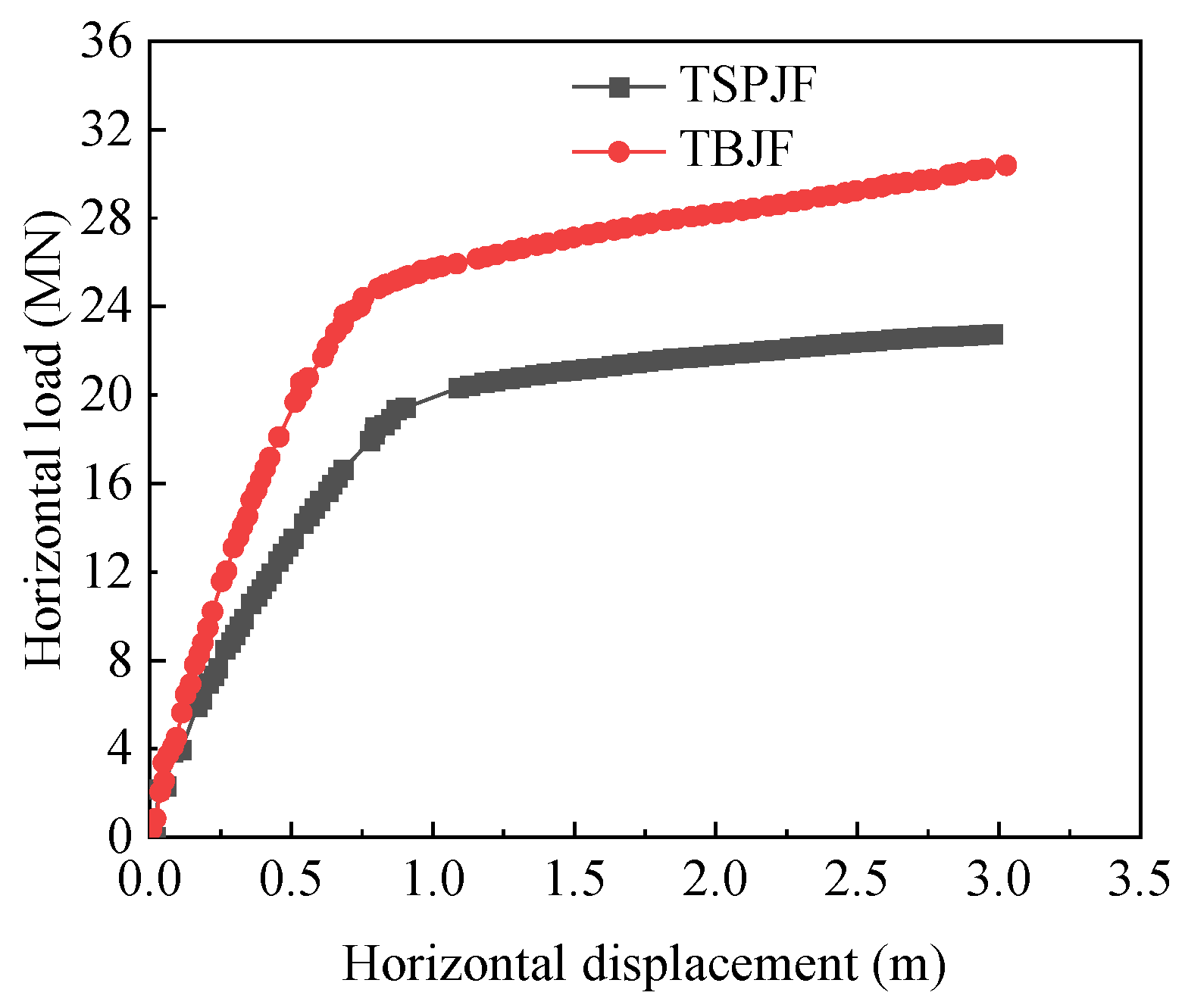
Figure 11 shows the horizontal load–displacement curves of TSPJF and TBJF when the loading direction is along the positive
x-axis. There are obvious inflection points in the two curves, and the loads corresponding to the inflection points can be regarded as the ultimate horizontal bearing capacity, so the horizontal bearing capacities of TSPJF and TBJF are 19.35 MN and 24.83 MN, respectively.
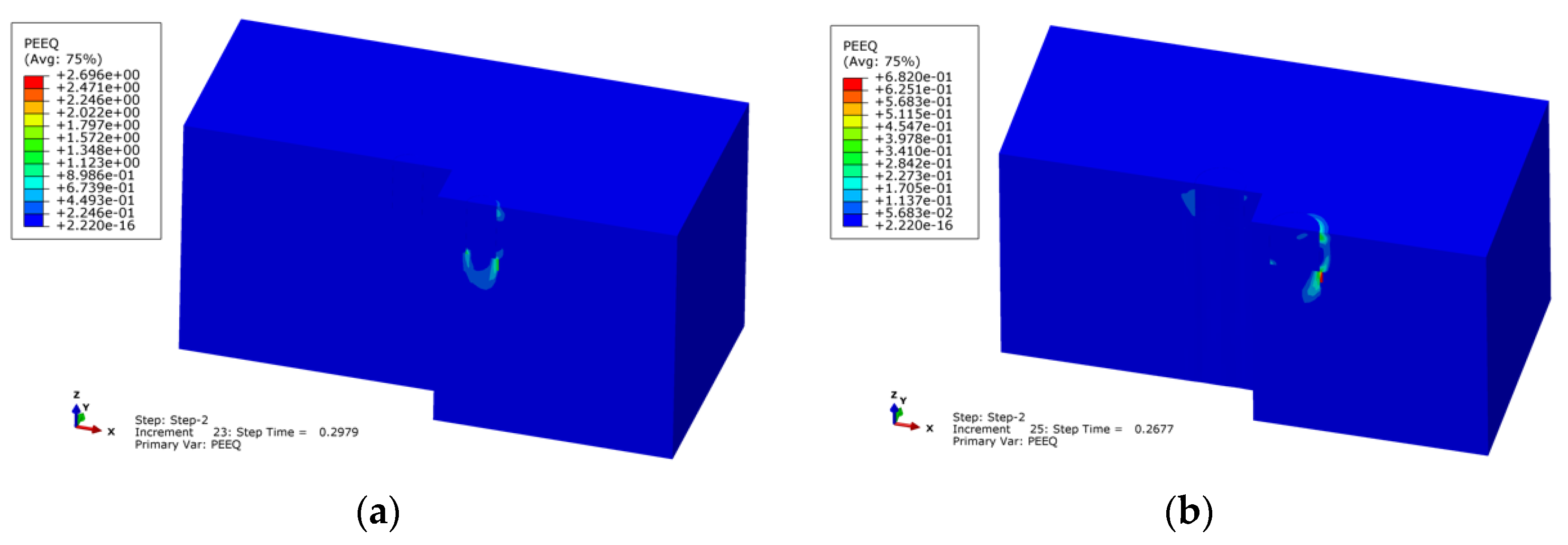
Figure 12 shows soil equivalent plastic strain contours at the 1# and 2# bucket central section for TSPJF and TBJF under the ultimate horizontal load. As shown in
Figure 12a, no plastic failure occurs in the soil around the 2# bucket of TSPJF. The plastic strain of the soil under the ultimate horizontal load is similar to that under the ultimate vertical load, and it mainly occurs at the end of the 1# bucket and extends downward to form a continuous “V-shaped” plastic failure zone. In addition, due to the extrusion of the bucket, there is also a certain plastic failure in the outer and upper soil of the 1# bucket on the forward side. As shown in
Figure 12b, the soil equivalent plastic strain contour of TBJF is obviously different from that of the TSPJF. There is no continuous “V-shaped” plastic failure zone at the end of the 1# bucket. The plastic damage of the soil mainly occurs on the outside and end of the 1# bucket on the forward side. Therefore, the TSPJF resists the horizontal load mainly by reaction generated in forward and backward buckets acting in tension and compression, respectively, while the TBJF resists it mainly by single bucket horizontal and bending resistance.
The distribution of earth pressure inside and outside skirt wall at the position of P1 and P2 of 1# bucket and 2# bucket along the skirt height is shown in
Figure 13. The distribution of earth pressure is consistent with the distribution of plastic strain shown in
Figure 12. The distribution of earth pressure of the two foundations is similar along the skirt height, but the earth pressure on the TSPJF is relatively small in value.
Figure 14 shows the lateral soil resistance on the inside and outside skirt walls of TSPJF and TBJF at different horizontal loads. The direction of the soil resistance is positive with the positive
x-axis. The lateral soil resistance curves of the two foundations have similar trends with the change of horizontal load. The magnitude and trend of soil resistances on the skirt wall of 2# and 3# buckets of TSPJF and TBJF are similar under the different horizontal loads, and the soil resistances on the 2# and 3# buckets are all smaller than that of 1# bucket. The lateral soil resistance of the TSPJF and TBJF under horizontal load mainly comes from the soil resistance on the outside skirt wall of 1# bucket; more precisely, it comes from the passive earth pressure area on the forward side and the outer of 1# bucket, which can also be shown from the plastic strain contours under the ultimate horizontal load.
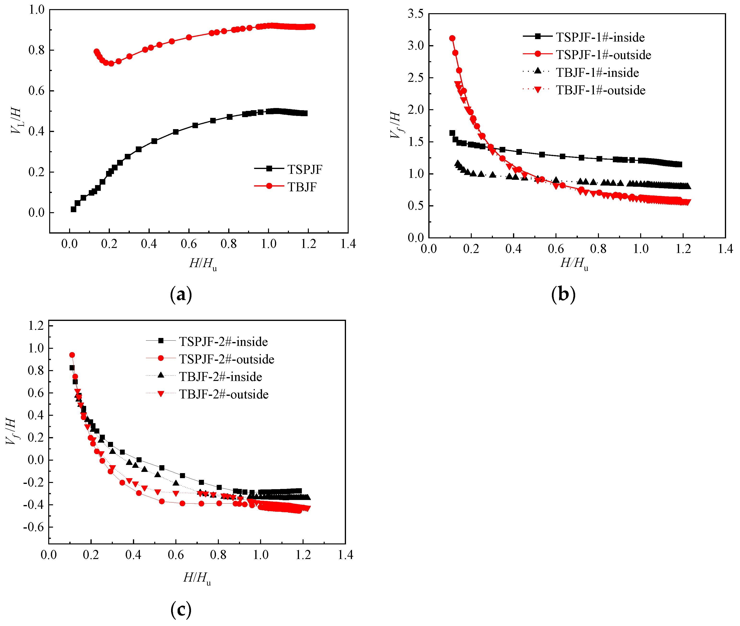
In order to further explore the difference in the horizontal bearing characteristics between the TSPJF and the TBJF. The variation of the dimensionless vertical resistances,
,
, provided by bucket lid, and inside and outside frictional resistance on the buckets with dimensionless horizontal load,
, are demonstrated in
Figure 15, where
H is the applied horizontal load;
is the uniaxial horizontal capacity. As shown in
Figure 15a, the vertical resistance on the 1# bucket lid of the TBJF is significantly higher than that of the TSPJF under the same horizontal load. The vertical resistance is about 0.5
for the TSPJF under the ultimate horizontal load, while it can reach 0.9
for the TBJF. As shown in
Figure 15b, the variation of the dimensionless vertical frictional resistance on the outside skirt of 1# bucket of the TSPJF and TBJF is similar, and the ratio of the bucket height to the bucket diameter has little effect on it. With the increase of the horizontal load, the dimensionless vertical frictional resistance on the outside skirt of 1# bucket gradually decreases, and the rate of decrease gradually slows down, and it is reduced to about 0.6 at the ultimate horizontal capacity. However, the dimensionless vertical frictional resistance on the outside skirt of 1# bucket of TSPJF is significantly larger than that of TBJF under the same horizontal load. The difference in vertical frictional resistance on the inside and outside skirt of the 2# bucket is small as shown in
Figure 15c.
3.2. Negative x-Axis Loading
The horizontal bearing characteristics of the TSPJF and TBJF under negative
x-axis loading are different from those under positive
x-axis loading.
Figure 16 shows soil equivalent plastic strain contours at the 1# and 2# bucket central section for TSPJF and TBJF under the ultimate horizontal load. The plastic failure of soil around 1# bucket mainly occurs at the end (in the passive region) and the top (in the active region) of the bucket under positive
x-axis loading. Due to the displacement of the bucket in the negative
x-axis direction, the outer soil on the forward side of 1# bucket is separated from the bucket during the loading process, which progressively produces active failure that forms a large plastic failure zone.
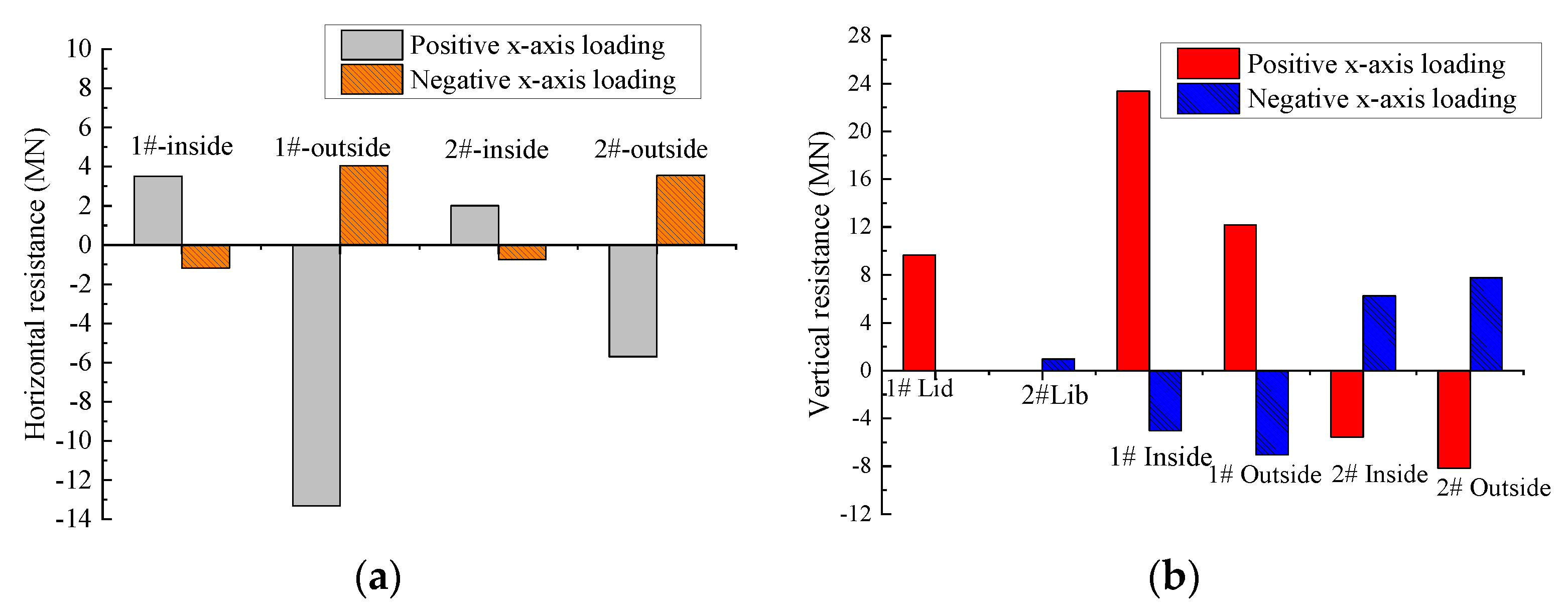
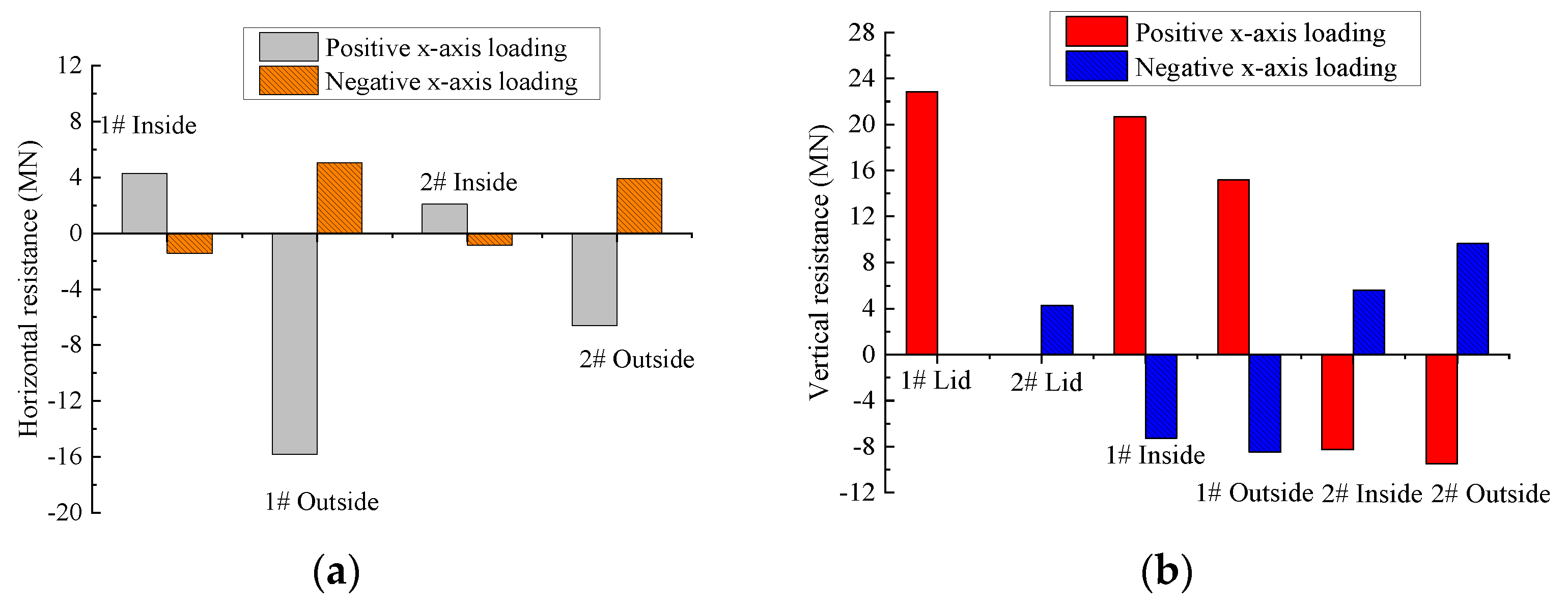
The horizontal and vertical resistance of each part of the buckets of the TSPJF and TBJF under ultimate horizontal load are shown in
Figure 17 and
Figure 18, respectively. It can be seen from
Figure 17a and
Figure 18a that the soil horizontal resistance on the inside and outside skirt wall of buckets under the positive
x-axis loading condition is greater than that under the negative
x-axis loading condition. Among them, the soil in the outer passive zone of 1# bucket provides the greatest resistance. As shown in
Figure 17b and
Figure 18b, the vertical resistance of the TSPJF and TBJF is mainly composed of the soil resistance on the 1# bucket lid, the inside and outside frictional resistance of each bucket under positive
x-axis loading condition. For the TSPJF, the inside frictional resistance of 1# bucket is the largest, followed by the outside frictional resistance of 1# bucket, and soil resistance on the 1# bucket lid, while for the TBJF, the soil resistance on the 1# bucket lid is the largest, followed by the inside frictional resistance of 1# bucket and the outside frictional resistance of 1# bucket. Under the negative
x-axis loading condition, the vertical resistance of the TSPJF and TBJF is mainly composed of the inside and outside frictional resistance of each bucket, while the soil resistance on the bucket lid is very small, especially for the TSPJF.
4. Comparison of Bearing Characteristics of TSPJF and TBJF under Overturning Moment
The TSPJF and TBJF resist the overturning moment with the reaction generated in windward and leeward bucket foundations acting in tension and compression, respectively [
15,
17]. Two loading directions are considered to analyze the monotonic moment bearing characteristics, including (1) 1# bucket in compression, and 2# and 3# bucket in tension, namely single bucket in compression, (2) 2# and 3# bucket in compression, and 1# bucket in tension, namely single bucket in tension.
4.1. Single Bucket in Compression
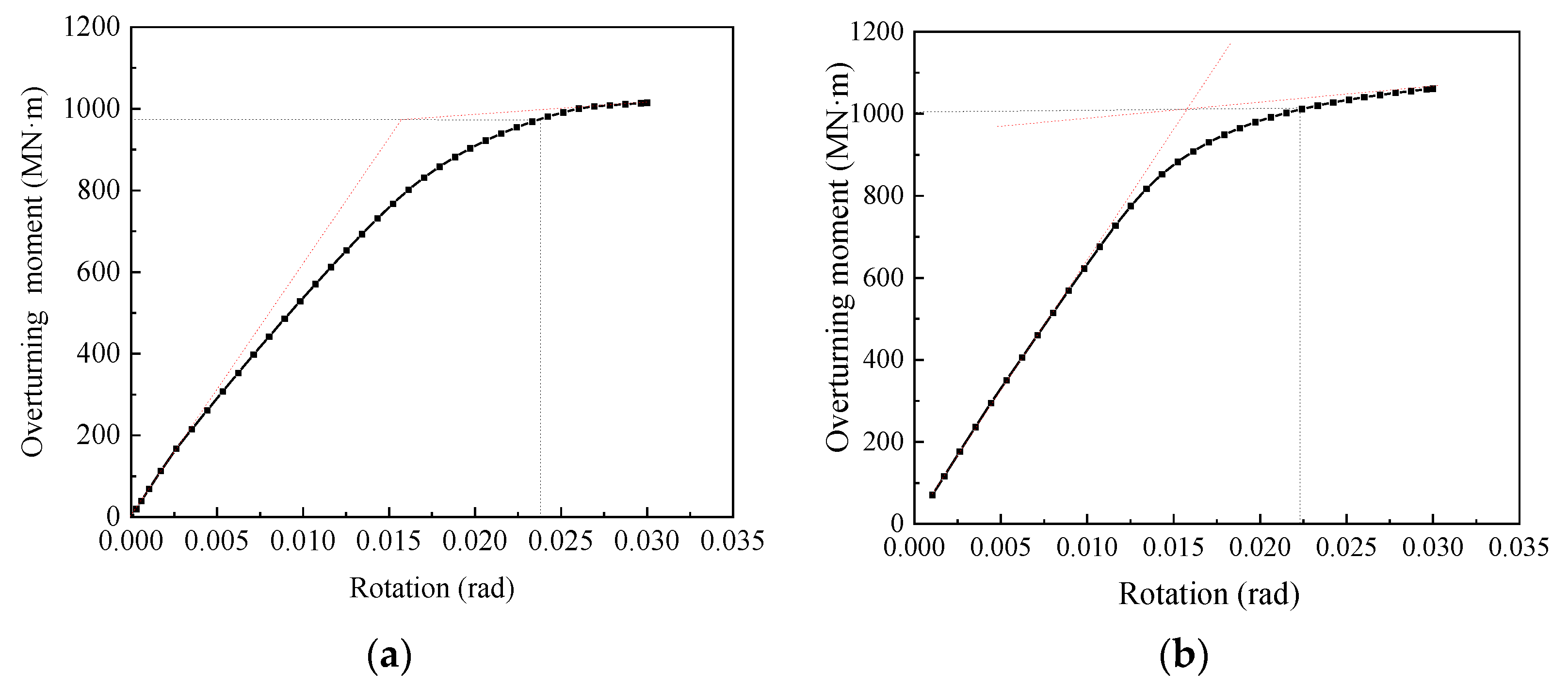
Figure 19 shows the overturning moment-rotation plots of the TSPJF and TBJF, which shows an inherently nonlinear growth with an elastic stiffness at small rotations. When the rotation exceeds about 0.02 rad, the slope of the curve decreases significantly. There are no obvious inflection points in the overturning moment–rotation curves. The ultimate overturning capacity can be obtained using the tangent intersection method proposed by Villalobos [
18], and the ultimate overturning capacity of TSPJF and TBJF are 980.42 MN·m and 1011.64 MN·m, respectively.
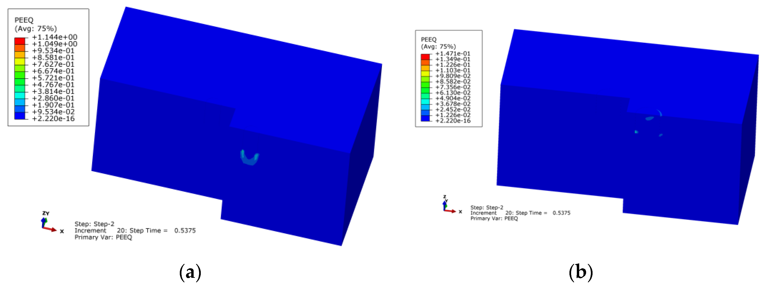
Figure 20 displays the soil equivalent plastic strain contours at the 1# and 2# bucket central section for the TSPJF and TBJF under the ultimate overturning moment. As shown in
Figure 20a, only the soil at the end of the 1# bucket has plastic failure occurring. The failure mode is consistent with the failure mode of the single bucket under the vertical load, which indicates that the displacement of the TSPJF under the overturning moment is dominated by rotation, while the translational displacement is almost negligible. As shown in
Figure 20b, there is no obvious plastic strain at the end of 1# bucket (bucket in compression) under the ultimate overturning moment, but the 2# bucket and 3# bucket (buckets in tension) are pulled out, so the ultimate moment capacity is directly related to the uplift capacity of the single bucket foundation.
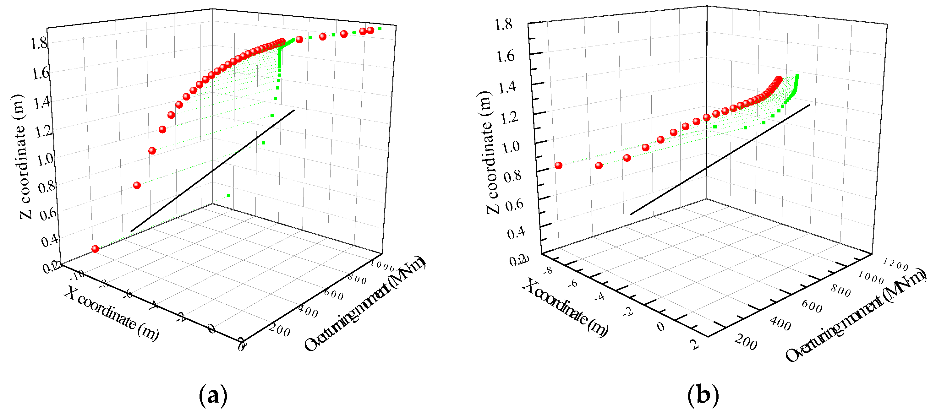
Figure 21 shows the diagram of the coordinates of the foundation rotation center at different overturning moments for the TSPJF and TBJF. At the initial stage of loading, the rotation center of the foundation is located at the midpoint of the line connecting the lid centers of the two buckets in tension (2# bucket and 3# bucket) for the TSPJF and TBJF. With the increase of the overturning moment, the rotation center gradually moves to the centroid of the foundation (
x = 0) in the horizontal direction, and moves up and away from the seabed in the vertical direction. The coordinates of the rotation center of the TSPJF and TBJF are (−5.87 m, 0m, 1.67 m,) and (−3.41 m, 0m, 1.25 m) under the ultimate overturning moment.
4.2. Single Bucket in Tension
The ultimate moment capacities of the TSPJF and TBJF in loading of the single bucket in tension are 495.5 MN·m and 641.14 MN·m, which is significantly smaller than that in loading of the single bucket in compression.
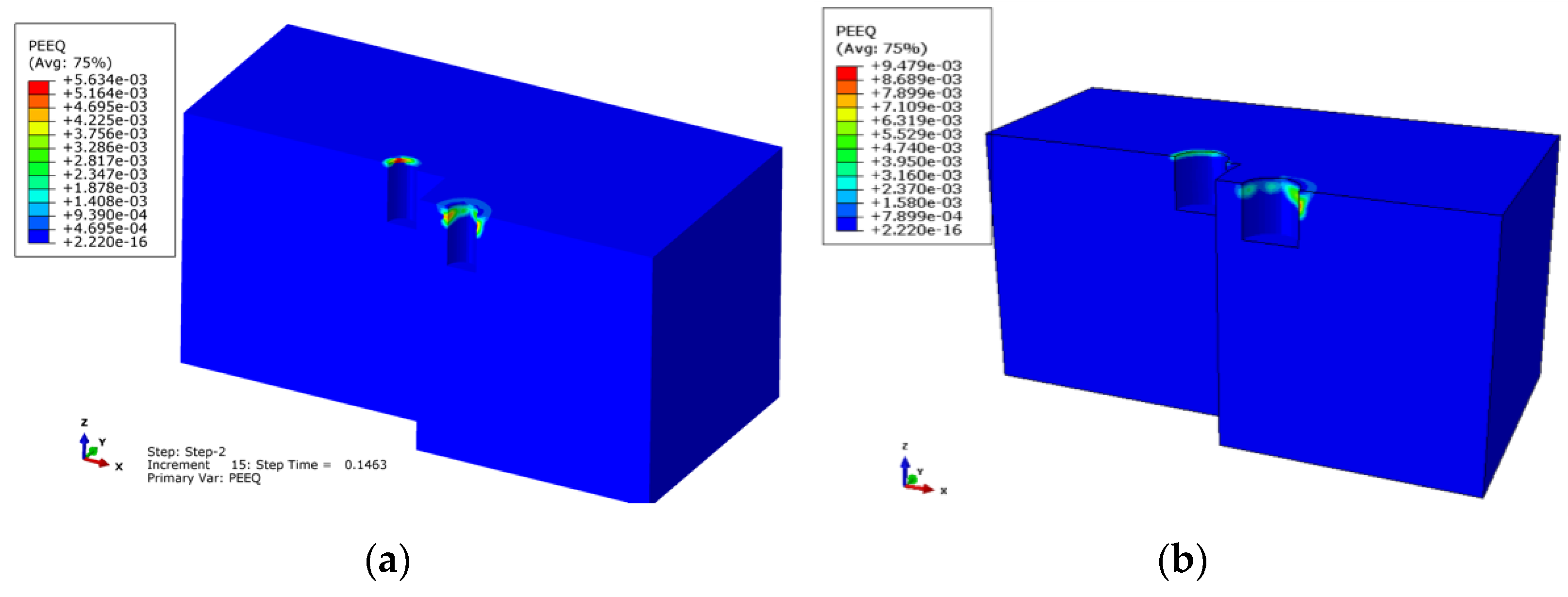
Figure 22 shows the soil equivalent plastic strain contours at the 1# and 2# bucket central section for the TSPJF and TBJF under the ultimate overturning moment. The plastic failure occurs in the soil around the top of the buckets including the buckets in compression and tension. In addition, the plastic failure area of the soil around the bucket in tension (1# bucket) is obviously larger than that around the bucket in compression (2# bucket).
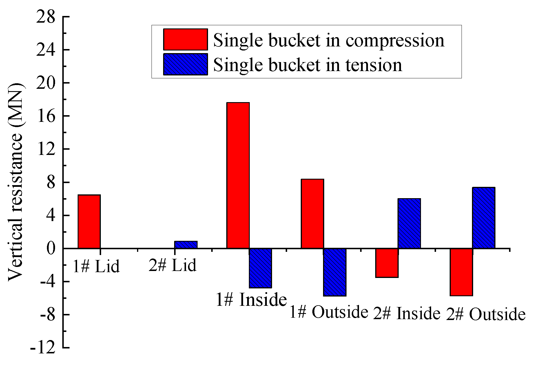
The horizontal resistance on the TSPJF and TBJF is relatively small under the ultimate overturning moment, so only the vertical resistances are analyzed.
Figure 23 shows the vertical resistance of each part of the buckets of the TSPJF in different loading directions. Different from the single bucket in compression condition, the vertical resistance on the bucket lid under the single bucket tension condition is very small, the overturning moment is mainly borne by the inside and outside frictional resistance. Combined with the soil equivalent plastic strain contours, it can be concluded that the failure mode of the TSPJF and TBJF in loading of the single bucket in tension is the pull-out failure of the bucket in tension.
5. Conclusions
In this study, the bearing characteristics of two tripod bucket jacket foundations with different height-diameter ratios, the TSPJF and TBJF, were compared under different monotonic loads. The analysis results indicate that the ratio of the bucket height to the bucket diameter has a great influence on the bearing performance and even the failure mode. The key conclusions are summarized as follows:
(1) The bearing modes of the two foundations under the vertical loads are different. The ultimate vertical load is mainly borne by the inside frictional resistance for the TSPJF, and its proportion is about 57%. However, for the wide and shallow foundation, TBJF, the ultimate vertical load is mainly borne by the lid resistance, and its proportion is about 42.7%.
(2) Two loading directions are considered to analyze the horizontal bearing characteristics. The foundations will take place translation and rotation under horizontal load. Under the positive x-axis loading, the horizontal resistance is mainly provided by the soil in the outer passive zone of 1# bucket. The vertical resistance of the TSPJF and TBJF is mainly composed of the soil resistance on the 1# bucket lid, the inside and outside frictional resistance of each bucket. For the TSPJF, the inside frictional resistance of 1# bucket is the largest, while, for the TBJF, the soil resistance on the 1# bucket lid is the largest. Under the negative x-axis loading condition, the vertical resistance of the TSPJF and TBJF is mainly composed of the inside and outside frictional resistance of each bucket, while the soil resistance on the bucket lid is very small, especially for the TSPJF.
(3) The overturning moments on the TSPJF and TBJF are resisted by the reaction generated in windward and leeward bucket foundations acting in tension and compression, respectively. The horizontal resistance on the TSPJF and TBJF is relatively small under the ultimate overturning moment. The ultimate moment capacities of the TSPJF and TBJF in loading of the single bucket in compression is significantly larger than that in loading of the single bucket in tension. Different from the single bucket in compression condition, the vertical resistance on the bucket lid under the single bucket tension condition is very small, and the overturning moment is mainly borne by the inside and outside frictional resistance. The failure mode of the TSPJF and TBJF in loading of the single bucket in tension is the pull-out failure of the bucket in tension.
Author Contributions
Conceptualization, C.L. and Y.G.; Methodology, C.L. and R.Y.; Software, R.Y. and C.L.; Validation, R.Y., C.L., and G.W.; Formal Analysis, R.Y. and C.L.; Writing—Original Draft Preparation, R.Y., C.L., G.W. and X.H.; Writing—Review and Editing, C.L., R.Y., and G.W.; Supervision, C.L. and Y.G.; Project Administration, Y.G., G.W., and X.H.; Funding Acquisition, Y.G., G.W., and X.H. All authors have read and agreed to the published version of the manuscript.
Funding
This research received no external funding.
Institutional Review Board Statement
Not applicable.
Informed Consent Statement
Not applicable.
Data Availability Statement
Not applicable.
Conflicts of Interest
The authors declare no conflict of interest.
References
- Ren, Y.; Vengatesan, V.; Shi, W. Dynamic analysis of a multi-column TLP floating offshore wind turbine with tendon failure scenarios. Ocean Eng. 2022, 245, 110472. [Google Scholar] [CrossRef]
- Zhang, J.; Cheng, W.; Cheng, X.; Wang, P.; Wang, T. Seismic responses analysis of suction bucket foundation for offshore wind turbine in clays. Ocean Eng. 2021, 232, 109159. [Google Scholar] [CrossRef]
- Le, C.; Zhang, J.; Ding, H.; Zhang, P.; Wang, G. Preliminary design of a submerged support structure for floating wind turbines. J. Ocean. Univ. China 2020, 19, 1265–1282. [Google Scholar] [CrossRef]
- Qi, W.G.; Tian, J.K.; Zheng, H.Y.; Wang, H.Y.; Yang, J.; He, G.L.; Gao, F.P. Bearing capacity of the high-rise pile cap foundation for offshore wind turbines. In Proceedings of the International Conference on Sustainable Development of Critical Infrastructure, Shanghai, China, 16–18 May 2014. [Google Scholar]
- Ma, H.; Lu, Z.; Li, Y.; Chen, C.; Yang, J. Permanent accumulated rotation of offshore wind turbine monopile due to typhoon-induced cyclic loading. Mar. Struct. 2021, 80, 103079. [Google Scholar] [CrossRef]
- Byrne, B.; Houlsby, G. Assessing novel foundation options for offshore wind turbines. In Proceedings of the World Maritime Technology Conference, London, UK, 6–10 March 2006. [Google Scholar]
- Le, C.; Ding, H.; Zhang, P. Prototype testing for the partial removal and re-penetration of the mooring dolphin platform with multi-bucket foundations. Mar. Struct. 2018, 59, 80–93. [Google Scholar] [CrossRef]
- Zhu, F.; Bienen, B.; O’Loughlin, C.; Cassidy, M.J.; Morgan, N. Suction caisson foundations for offshore wind energy: Cyclic response in sand and sand over clay. Geotechnique 2019, 69, 924–931. [Google Scholar] [CrossRef]
- Hung, L.C.; Kim, S.R. Evaluation of combined horizontal-moment bearing capacities of tripod bucket. Ocean Eng. 2014, 85, 100–109. [Google Scholar] [CrossRef]
- foundations in undrained clay. Ocean Eng. 2014, 85, 100–109.
- Kim, S.R.; Hung, L.C.; Oh, M. Group effect on bearing capacities of tripod bucket foundations in undrained clay. Ocean Eng. 2014, 79, 1–9. [Google Scholar] [CrossRef]
- Barari, A.; Glitrup, K.; Christiansen, L.R.; Ibsen, L.B.; Choo, Y.W. Tripod suction caisson foundations for offshore wind energy and their monotonic and cyclic responses in silty sand: Numerical predictions for centrifuge model tests. Soil Dyn. Earthq. Eng. 2021, 149, 106813. [Google Scholar] [CrossRef]
- Liu, B.; Zhang, Y.H.; Ma, Z.R.; Andersen, K.H.; Jostad, H.P.; Liu, D.H.; Pei, A.G. Design considerations of suction caisson foundations for offshore wind turbines in Southern China. Appl. Ocean Res. 2020, 104, 102358. [Google Scholar] [CrossRef]
- Kim, D.J.; Choo, Y.W.; Kim, J.H.; Kim, S.; Kim, D.S. Investigation of monotonic and cyclic behavior of tripod suction bucket foundations for offshore wind towers using centrifuge modeling. J. Geotech. Geoenviron. Eng. 2014, 140, 04014008. [Google Scholar] [CrossRef]
- Wang, L.; Wang, H.; Zhu, B.; Hong, Y. Comparison of monotonic and cyclic lateral response between monopod and tripod bucket foundations in medium dense sand. Ocean Eng. 2018, 155, 88–105. [Google Scholar] [CrossRef]
- Faizi, K.; Faramarzi, A.; Dirar, S.; Chapman, D. Investigating the monotonic behaviour of hybrid tripod suction bucket foundations for offshore wind towers in sand. Appl. Ocean Res. 2019, 89, 176–187. [Google Scholar] [CrossRef]
- Tran, N.X.; Kim, S.R. Evaluation of horizontal and moment bearing capacities of tripod bucket foundations in sand. Ocean Eng. 2017, 140, 209–221. [Google Scholar] [CrossRef]
- Senders, M. Suction Caissons in Sand as Tripod Foundations for Offshore Wind Turbines; University of Western Australia: Perth, Australia, 2009. [Google Scholar]
Figure 1.
Models of the TSPJF and TBJF. (a) TSPJF, (b) TBJF, and (c) coordinates and bucket number.
Figure 1.
Models of the TSPJF and TBJF. (a) TSPJF, (b) TBJF, and (c) coordinates and bucket number.
Figure 2.
Soil numerical model.
Figure 2.
Soil numerical model.
Figure 3.
Vertical load–displacement curve of the TSPJF and TBJF at the loading points.
Figure 3.
Vertical load–displacement curve of the TSPJF and TBJF at the loading points.
Figure 4.
Soil equivalent plastic strain contours at the 2# and 3# bucket central section for the TSPJF and TBJF under the ultimate vertical load. (a) TSPJF, (b) TBJF.
Figure 4.
Soil equivalent plastic strain contours at the 2# and 3# bucket central section for the TSPJF and TBJF under the ultimate vertical load. (a) TSPJF, (b) TBJF.
Figure 5.
The inside and outside earth pressure of 1# of the TSPJF and TBJF. (a) TSPJF, (b) TBJF.
Figure 5.
The inside and outside earth pressure of 1# of the TSPJF and TBJF. (a) TSPJF, (b) TBJF.
Figure 6.
Comparison of earth pressure along the depth between the TSPJF and TBJF. (a) earth pressure on inner skirt of 1# bucket at P1; (b) earth pressure on inner skirt of 1# bucket at P2; (c) earth pressure on outer skirt of 1# bucket at P1; (d) earth pressure on outer skirt of 1# bucket at P2.
Figure 6.
Comparison of earth pressure along the depth between the TSPJF and TBJF. (a) earth pressure on inner skirt of 1# bucket at P1; (b) earth pressure on inner skirt of 1# bucket at P2; (c) earth pressure on outer skirt of 1# bucket at P1; (d) earth pressure on outer skirt of 1# bucket at P2.
Figure 7.
Resistance provided by each part of the foundations at different vertical loads. (a) TSPJF, (b) TBJF.
Figure 7.
Resistance provided by each part of the foundations at different vertical loads. (a) TSPJF, (b) TBJF.
Figure 8.
Bearing proportion of each part of the foundations at different vertical loads. (a) inside and outside frictional resistance, lid resistance, (b) end resistance.
Figure 8.
Bearing proportion of each part of the foundations at different vertical loads. (a) inside and outside frictional resistance, lid resistance, (b) end resistance.
Figure 9.
Percentage of each part of the foundation under ultimate vertical load.
Figure 9.
Percentage of each part of the foundation under ultimate vertical load.
Figure 10.
Circumferential distribution of earth pressure on the inside and outside skirt of 1# bucket of TSPJF and TBJF at different depths. (a) earth pressure on the inside skirt of 1# bucket of the TSPJF, (b) earth pressure on the outside skirt of 1# bucket of the TSPJF, (c) earth pressure on the inside skirt of 1# bucket of the TBJF, (d) earth pressure on the outside skirt of 1# bucket of the TBJF.
Figure 11.
Horizontal load–displacement curve of the TSPJF and TBJF at the loading points.
Figure 11.
Horizontal load–displacement curve of the TSPJF and TBJF at the loading points.
Figure 12.
Soil equivalent plastic strain contours at 1# and 2# bucket central section for the TSPJF and TBJF under the ultimate horizontal load. (a) TSPJF, (b) TBJF.
Figure 12.
Soil equivalent plastic strain contours at 1# and 2# bucket central section for the TSPJF and TBJF under the ultimate horizontal load. (a) TSPJF, (b) TBJF.
Figure 13.
Distribution of earth pressure inside and outside TSPJF and TBJF along the skirt height under ultimate horizontal load. (a) 1# bucket of the TSPJF, (b) 2# bucket of the TSPJF, (c) 1# bucket of the TBJF, (d) 2# bucket of the TBJF.
Figure 13.
Distribution of earth pressure inside and outside TSPJF and TBJF along the skirt height under ultimate horizontal load. (a) 1# bucket of the TSPJF, (b) 2# bucket of the TSPJF, (c) 1# bucket of the TBJF, (d) 2# bucket of the TBJF.
Figure 14.
Lateral soil resistance on the skirt wall of the TSPJF and TBJF at the different horizontal loads. (a) soil resistance on the inside skirt wall of the TSPJF, (b) soil resistance on the outside skirt wall of the TSPJF, (c) soil resistance on the inside the skirt wall of the TBJF, (d) soil resistance on the outside the skirt wall of the TBJF.
Figure 15.
Vertical resistance of each part of the foundations at different horizontal loads. (a) lid resistance of 1# bucket, (b) frictional resistance of 1# bucket, (c) frictional resistance of 2# bucket.
Figure 15.
Vertical resistance of each part of the foundations at different horizontal loads. (a) lid resistance of 1# bucket, (b) frictional resistance of 1# bucket, (c) frictional resistance of 2# bucket.
Figure 16.
Soil equivalent plastic strain contours at 1# and 2# bucket central section for the TSPJF and TBJF under the ultimate horizontal load. (a) TSPJF, (b) TBJF.
Figure 16.
Soil equivalent plastic strain contours at 1# and 2# bucket central section for the TSPJF and TBJF under the ultimate horizontal load. (a) TSPJF, (b) TBJF.
Figure 17.
Horizontal and vertical resistance of each part of the buckets of TSPJF under ultimate horizontal load. (a) horizontal resistance, (b) vertical resistance.
Figure 17.
Horizontal and vertical resistance of each part of the buckets of TSPJF under ultimate horizontal load. (a) horizontal resistance, (b) vertical resistance.
Figure 18.
Horizontal and vertical resistance of each part of the buckets of TBJF under ultimate horizontal load. (a) horizontal resistance, (b) vertical resistance.
Figure 18.
Horizontal and vertical resistance of each part of the buckets of TBJF under ultimate horizontal load. (a) horizontal resistance, (b) vertical resistance.
Figure 19.
Overturning moment-rotation plot for the TSPJF and TBJF. (a) TSPJF, (b) TBJF.
Figure 19.
Overturning moment-rotation plot for the TSPJF and TBJF. (a) TSPJF, (b) TBJF.
Figure 20.
Soil equivalent plastic strain contours at the 1# and 2# bucket central section for the TSPJF and TBJF under the ultimate overturning moment. (a) TSPJF, (b) TBJF.
Figure 20.
Soil equivalent plastic strain contours at the 1# and 2# bucket central section for the TSPJF and TBJF under the ultimate overturning moment. (a) TSPJF, (b) TBJF.
Figure 21.
Rotation center under different overturning moments. (a) TSPJF, (b) TBJF.
Figure 21.
Rotation center under different overturning moments. (a) TSPJF, (b) TBJF.
Figure 22.
Soil equivalent plastic strain contours at the 1# and 2# bucket central section for the TSPJF and TBJF under the ultimate overturning moment. (a) TSPJF, (b) TBJF.
Figure 22.
Soil equivalent plastic strain contours at the 1# and 2# bucket central section for the TSPJF and TBJF under the ultimate overturning moment. (a) TSPJF, (b) TBJF.
Figure 23.
Vertical resistance of each part of the buckets of TSPJF under the ultimate overturning moment.
Figure 23.
Vertical resistance of each part of the buckets of TSPJF under the ultimate overturning moment.
Table 1.
Main parameters of the foundations.
Table 1.
Main parameters of the foundations.
| Foundation | Diameter of Suction Pile/Bucket, D (m) | Height of Suction Pile/Bucket, H (m) | Thickness of Lid, t1 (m) | Thickness of Skirt Wall, t2 (m) | Ration of Height to Diameter |
|---|
| TSPJF | 10 | 20 | 0.05 | 0.04 | 2 |
| TBJF | 17 | 17 | 0.05 | 0.04 | 1 |
Table 2.
Soil parameters.
Table 2.
Soil parameters.
| Item | Saturated Bulk Density, γ (kN·m3) | Modulus of Elasticity, E (MPa) | Cohesion c
(kPa) | Internal Friction Angle φ(°) |
|---|
| Value | 19 | 30 | 2.6 | 30 |
| Publisher’s Note: MDPI stays neutral with regard to jurisdictional claims in published maps and institutional affiliations. |
© 2022 by the authors. Licensee MDPI, Basel, Switzerland. This article is an open access article distributed under the terms and conditions of the Creative Commons Attribution (CC BY) license (https://creativecommons.org/licenses/by/4.0/).


