Article

Learning-Based Nonlinear Model Predictive Controller for Hydraulic Cylinder Control of Ship Steering System

Logistics Engineering College, Shanghai Maritime University, Shanghai 201306, China
*
Author to whom correspondence should be addressed.
J. Mar. Sci. Eng. 2022, 10(12), 2033; https://doi.org/10.3390/jmse10122033
Submission received: 27 October 2022 / Revised: 30 November 2022 / Accepted: 7 December 2022 / Published: 19 December 2022

Abstract

:
The steering mechanism of ship steering gear is generally driven by a hydraulic system. The precise control of the hydraulic cylinder in the steering mechanism can be achieved by the target rudder angle. However, hydraulic systems are often described as nonlinear systems with uncertainties. Since the system parameters are uncertain and system performances are influenced by disturbances and noises, the robustness cannot be satisfied by approximating the nonlinear theory by a linear theory. In this paper, a learning-based model predictive controller (LB-MPC) is designed for the position control of an electro-hydraulic cylinder system. In order to reduce the influence of uncertainty of the hydraulic system caused by the model mismatch, the Gaussian process (GP) is adopted, and also the real-time input and output data are used to improve the model. A comparative simulation of GP-MPC and MPC is performed assuming that the interference and uncertainty terms are bounded. Consequently, the proposed control strategy can effectively improve the piston position quickly and precisely with multiple constraint conditions.

1. Introduction

Valve-controlled hydraulic systems are characterized by high power density, fast response time, and high shock resistance. They are widely used in various fields of military, and civilian industries, such as robotics such as robotics [1], vehicles [2], and marine and offshore industry [3,4,5]. A valve-controlled hydraulic system is a typical electromechanical system that contains mechanical, control, and hydraulic subsystems. In the hydraulic control, the valve control uses a quantitative oil pump. The amount of oil input by various working valves cannot be changed, and the working speed can only be adjusted in stages. Pump control is achieved by using a more advanced variable oil pump, and can also be driven by a fixed displacement pump, such as a piston pump, gear pump or satellite pump [6] In addition to the necessary control valves, the variables of the oil pump provide more room for adjustment of operating conditions such as speed. The modeling process of valve-controlled hydraulic systems usually involves many time-varying parameters, and nonlinear characteristics [7]. The most effective and proven control method is nonlinear control using the complete dynamic equations of the system. The precise control of the valve-controlled hydraulic system is performed through the design of continuous control laws of nonlinear dynamic equations and stable and accurate control with inaccurate models. Therefore, to accurately characterize the valve-controlled hydraulic system, a detailed analysis of the actual system and the dynamic change process of each state within the system is required.
The valve-controlled hydraulic system model is primarily a fusion mechanism model. The fusion mechanism model is a direct mathematical model of the system based on the relationship between system parameters, input and output variables using physical laws or experimental data. This approach requires that the structure and parameters of the system are known. However, mathematical models struggle to adequately explain the dynamic properties of hydraulic cylinders, such as nonlinear friction and external disturbances. For example, the position control system is mainly used to drive the actuator to complete the various actions required by the process. The process needs to be completed quickly by the positioning system, and the parameters of each step are strictly controlled.
The classical linear control method does not need to consider the dynamics of the model and can directly adjust the control parameters on-site based on the test results. However, if the stability and control performance of the system are to be fundamentally improved, at least a linearized model of the valve-controlled hydraulic system and some basic hydraulic parameters need to be obtained. It is worth noting that PID control gains often do not meet the system’s performance requirements if there is uncertainty in the system. Furthermore, due to the complexity of the hydraulic system’s dynamic model, linear control approaches cannot accurately incorporate the system’s dynamic features. Errors in models and parameters are difficult to avoid. This limits the closed-loop response speed of pure feedback linearized control. In order to address the stability and accuracy of control when the model is inaccurate, it is necessary to reduce the model error while ensuring the speed and stability of control in the presence of a small amount of bounded error. In [8], the proposed fuzzy logic control (FLC) controller has the advantage of minimizing the control energy and the system controller has a faster response and zero steady-state error. In [9], a complimentary sliding mode controller is proposed to reduce overshoot and provide faster response. In [10], Wang et al. estimated the weight of safety and displacement factors to the optimization index, ensuring a complex multi-objective optimization problem and improving centrifugal pump performance. In addition, adaptive algorithms are extensively used to approximate the real model and obtain control laws with real control inputs. While improving the system response characteristics, a high gain robust control is used to ensure the stability of the system in the presence of errors. The algorithm has been successfully applied to different hydraulic motion control systems [11,12,13,14,15]. Recently, the hybrid algorithm of fuzzy logic and adaptive neuro-fuzzy inference system effectively avoids the local optimal solution [16].
Model predictive control (MPC) is a computerized control algorithm for real industrial processes. MPC models are less demanding, more robust, and simpler to design. MPC has a significant advantage over other model-based control techniques to handle constraints online [17]. MPC is widely used in chemical process control [18], automotive systems [19], robotics [20], and hydraulic systems in [21,22] industries. However, the dynamics of hydraulic systems are too complex, and some complex but important dynamics are often neglected due to the difficulty of modeling. Hydraulic systems are highly nonlinear [23] and traditional MPC online calculations are difficult [24,25]. The use of linear models has several limitations, and machine learning techniques may handle nonlinear issues and work well for complicated modeling. Many MPC control strategies based on fuzzy theory and neural networks have emerged in recent reports [26,27,28]. However, fuzzy modeling overly relies on a priori knowledge [29]; neural networks have poor generalization ability [27], and easily fall into the local minima problem [30]. Traditional modeling methods require a sufficiently large sample size, but in practice, the sample size is usually limited [31]. The above LB-MPC method further improves the prediction model’s accuracy and reduces the system’s steady-state error. However, their limitations are that they do not consider the influence of noise mixed with the collected signal, and the output value of the prediction model cannot be explained. Meanwhile, most of the traditional learning algorithms are based on the principle of empirical risk minimization. The higher the accuracy of the finite sample fit, the worse the generalization ability of the model [32]. In [33], GP is used for model learning of MPC models. GP almost does not require prior knowledge and considers the training set samples mixed with noise. The predicted output value has probabilistic significance, and the number of samples required is less, which can directly give the nonlinear description of model uncertainty [34].
This paper’s primary contribution is the suggestion of an actuator control approach for hydraulic systems based on the GP model. From the online measurements of hydraulic cylinder pressure and load–displacement in N states, we utilize GP to learn the uncertainty in the hydraulic valve control system. We next apply GP regression to quantify the uncertainty associated with state and input. The output findings with confidence intervals are achieved by fitting the mixed noise data, and the discrete mathematical model produced has high accuracy. The findings demonstrate that the single-step prediction time is shortened due to fewer samples and that the mean square error of the piston forecast position increment is modest. The problem of hydraulic system model mismatch and output overshoot is effectively solved, and the fast position control without overshoot is realized.
The structure of this article is as follows. Section 2 describes the mathematical model of the hydraulic system. Section 3 introduces the LB-NMPC strategy based on Gaussian process. In Section 4, we designed the valve-controlled hydraulic position LB-NMPC controller and verified its effectiveness.

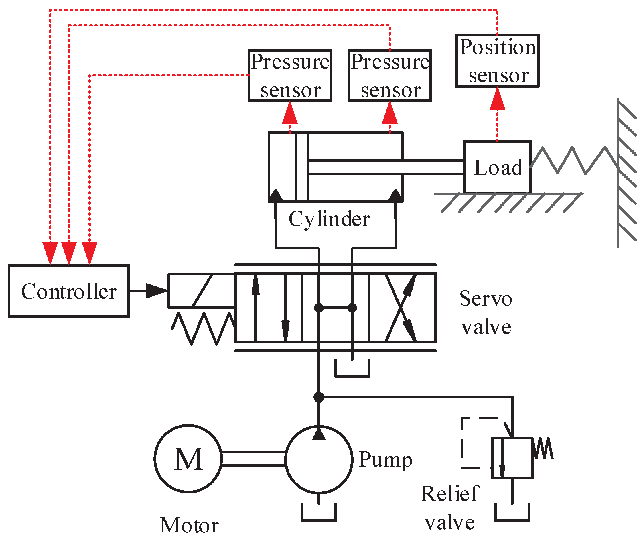
2. Modeling of Valve-Controlled Hydraulic System
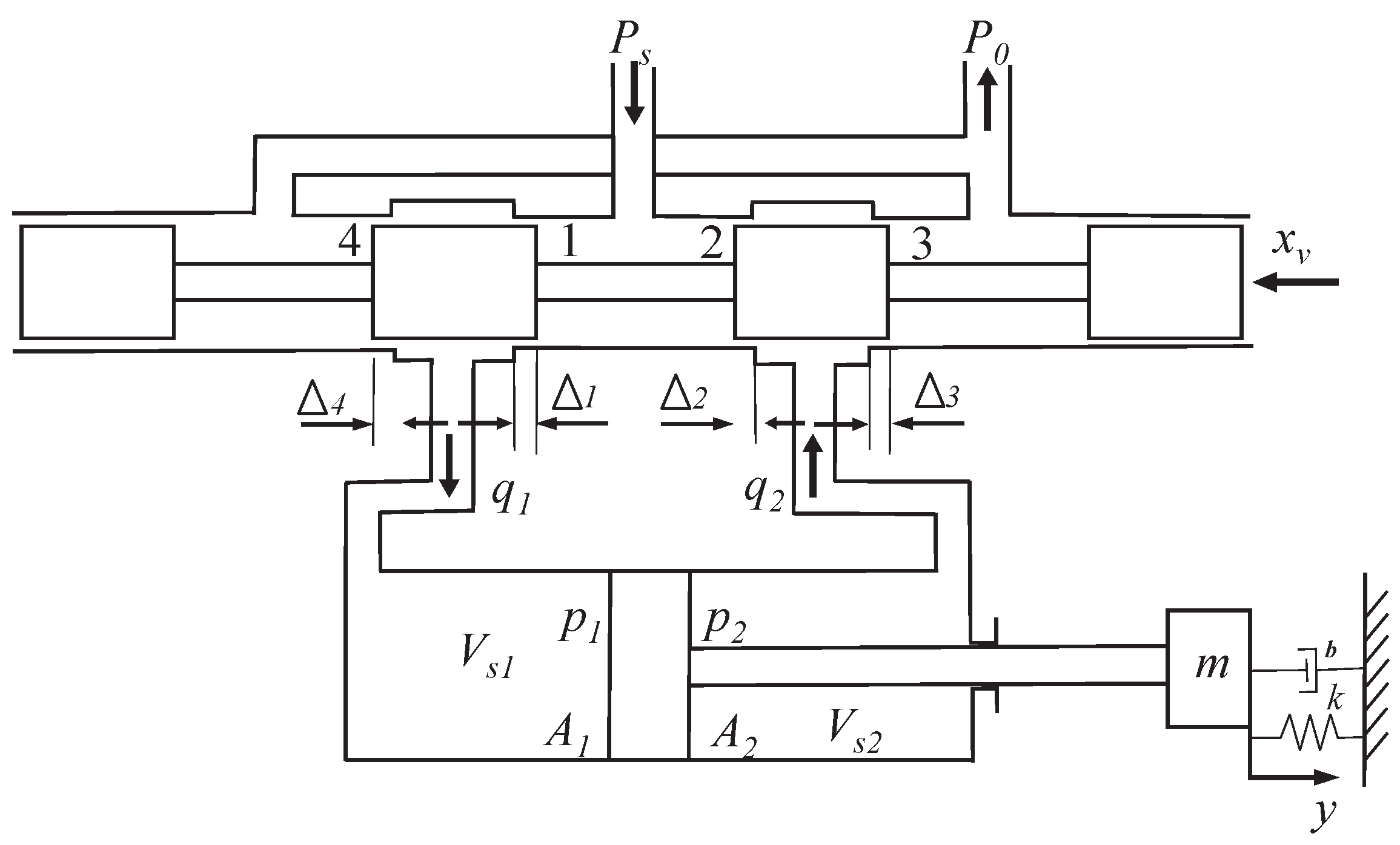
The structure of the valve-controlled servo system can be simplified in Figure 1, which mainly includes a hydraulic cylinder, servo valve, and mass load. In order to obtain a generalized nonlinear model of the system, it is assumed that the hydraulic cylinder is an asymmetric hydraulic cylinder. The power spool of the servo valve in Figure 2 is a four-shoulder valve. In practical applications, due to processing errors and other reasons, the servo valve, especially some proportional valve ports actually have a certain amount of positive overlap. The positive overlap between the spool and the four-valve ports is represented by Δ i , i = 1 , , 4 . The servo valve is a zero opening servo valve when Δ i = 0 and a positive opening servo valve when Δ i < 0 . For simplicity, assume that the 4 valve ports are rectangular. This study is only for simulation verification, using the state equation of the valve-controlled cylinder system in the literature [35].

2.1. Solenoid Valve

The flow rates of the 4 valve ports of the solenoid valve are:
q s v 1 = 0 x v Δ 1 C d w 1 ( x v Δ 1 ) 2 ( p s p 1 ) / ρ x v > Δ 1 q s v 2 = 0 x v Δ 2 C d w 1 ( x v + Δ 1 ) 2 ( p s p 1 ) / ρ x v < Δ 2 q s v 3 = 0 x v Δ 3 C d w 1 ( x v Δ 3 ) 2 ( p s p 1 ) / ρ x v > Δ 3 q s v 4 = 0 x v Δ 4 C d w 4 ( x v + Δ 4 ) 2 ( p 1 p 0 ) / ρ x v < Δ 4
where x v is the spool displacement of the solenoid valve; p 1 and p 2 are the two-chamber forces of the hydraulic cylinder; p 0 is the return pressure of the hydraulic source; p s is the oil supply pressure of the hydraulic source; w i is the area gradient of the ith valve port of the solenoid valve, i = 1 , 2 , 3 , 4 ; C d is the flow coefficient of the solenoid valve; ρ is the density of the hydraulic oil.

2.2. Solenoid Valve Working at Left End

When the solenoid valve is working in the left position, the oil pushes the piston to the right, the pressure of the right working chamber p 2 = 0 , and the flow into the left working chamber of the hydraulic cylinder at this time mainly includes: (a) loss caused by oil compression; (b) most of the flow is used to push the piston to move and ultimately act on the load; (c) considering the gap between the piston and the cylinder wall of the hydraulic cylinder, there is flow leakage between the left and right working chambers. The oil compressibility q 11 can be expressed as
q 11 = V 1 E y p ˙ 1
The flow used to push the piston can be expressed as
q 12 = A s 1 y ˙
The leakage compensation between the two chambers of the hydraulic cylinder can be expressed as
q 13 = K c i p 1
At this point, the flow continuity equation of the system can be expressed as
q 1 = q 11 + q 12 + q 13
Substituting Equations (2)–(4) into Equation (5), we obtain:
q 1 = V 1 E y p ˙ 1 + A s 1 y ˙ + K c i p 1
where V 1 is the volume of the left working chamber of the hydraulic cylinder; E y is the equivalent volume modulus of elasticity; p 1 is the pressure of the left working chamber of the hydraulic cylinder; A s 1 is the effective area of the left working chamber of the hydraulic cylinder; K c i is the leakage coefficient between the two chambers of the hydraulic cylinder; q 1 represents the output flow of the pump at this time, which can be expressed as
q 1 = D p n
where D p is the pump displacement; n is the pump speed (motor speed).

2.3. Solenoid Valve Working at Right End

When the solenoid valve is working in the left position, the oil pushes the piston to move to the right, the pressure of the left working chamber is then p 1 = 0 . Similar to the left position, the flow entering the left working chamber of the hydraulic cylinder at this time mainly includes: (a) loss caused by oil compression; (b) most of the flow is used to push the piston to move and ultimately act on the load; (c) considering the gap between the piston and the cylinder wall of the hydraulic cylinder, there is flow leakage between the left and right working chambers.
q 2 = V 2 E y p ˙ 2 + A s 2 y ˙ + K c i p 2
where V 2 is the volume of the right working chamber of the hydraulic cylinder; p 2 is the pressure of the right working chamber of the hydraulic cylinder; A s 2 is the effective area of the right working chamber of the hydraulic cylinder. At this time, the flow direction is opposite to that of working in the left position, which can be expressed as
q 2 = D p n
where D p is the pump displacement; n is the pump speed (motor speed).

2.4. Dynamical Model of the Cylinder

In the hydraulic system, the pump output flow enters the hydraulic cylinder through the solenoid valve, and finally drives the load to move. The force analysis of the load, the force balance equation can be expressed as
p 1 A s 1 p 2 A s 2 = m y ¨ + b y ˙ + k y
where m is the mass of the slider; b is the damping coefficient of the system; k is the spring stiffness coefficient; y is the displacement of the piston. According to the actual control requirements, y is restricted, that is, 0 y y max , and y max represents the maximum allowable displacement of the piston.
The input signal of the selected motor has a linear relationship with the speed of the motor (equal to the speed of the pump), so the relationship between the input signal of the motor and the speed of the pump can be expressed as
n = 0 , u < 0 K n u , u 0
where K n is the output-to-input ratio of the motor; u is the input signal of the motor. At the same time, considering the unidirectional rotation of the one-way pump and the limitation of the maximum speed n max , then
0 n = K n u n max
It can be clearly seen from the above analysis that when the solenoid valve is in different working positions, there are constraints on both the input variable and the output variable. If the solenoid valve cannot meet its constraints during the working process of the system, the system will become a strictly nonlinear system. We need a controller under the conditions of satisfying the system constraints, it will move to the desired target position without overshoot in one direction to achieve the desired target position.

2.5. Model of Nonlinear State

Define the state variable x = [ x 1 , x 2 , x 3 , x 4 ] T = [ y , y ˙ , p ˙ 1 , p ˙ 2 ] T , the non-sexual state equation of the valve-controlled hydraulic cylinder power mechanism:
x ˙ 1 = x 2 x ˙ 2 = 1 m ( A s 1 x 3 A s 2 x 4 b x 2 k x 1 ) x 3 = E y f 1 ( x v , x 3 ) K c i ( x 3 x 4 ) A s 1 x 2 V 1 x 4 = E y f 2 ( x v , x 4 ) K c i ( x 3 x 4 ) A s 2 x 2 V 2
It should be pointed out that the dynamic characteristics of the solenoid valve are not considered in the above-mentioned non-sexual equation of the state mathematical model, but the spool displacement x v is used as the control input. From Equation (1). we can get f 1 x v , p 1 = q s v 1 q s v 4 , f 2 x v , p 1 = q s v 2 q s v 2 , f i is the function of the flow into and out of the two chambers of the hydraulic cylinder with respect to x v and p i , i = 1 , 2 .

3. Algorithm Design

MPC is designed based on the prediction model. The structure is shown in Figure 3, and the hydraulic actuator is the controlled object. We use GP to predict the input noise online and improve the nonlinear model of the system. According to the actual system position output at the current moment and the command voltage and load force of the servo valve at the next moment, the position output of the prediction model at the next moment is obtained to reduce the error between the prediction model and the actual system. The quadratic optimization objective function is established and solved continuously in a limited time domain. The first optimal command voltage value calculated each time is output to the actual system.

3.1. Model Predictive Control

We consider a class of nonlinear dynamical systems modeled as
x ( k + 1 ) = f ( x ( k ) , u ( k ) ) + w ( k )
The model consists of a known nominal part state vector and an unknown disturbance part. x ( k ) R n is the current state. The model is composed of a known nominal part state vector, x ( k + 1 ) is the state at the next sample time, u ( k ) R m is the control input. w ( k ) is the uncertainty that exists at each sampling moment of the system that is assumed to be normally distributed.
Assumption 1:
w ( k ) is the uncertainty in the process of the hydraulic system and we consider it to obey the normal distribution at each sampling time k.
Assumption 2:
The nonlinear hydraulic valve control system (14) is controllable and observable. f : X × U X is a continuous Lipschitz function.
Assumption 3:
For the initial conditions, the nonlinear hydraulic valve control system model has a unique solution, that is, there exists an optimal control policy π * .
In this paper, we use GP regression to learn the uncertainty in the hydraulic valve control system from the input and output data. We collected N state and input measurement values of the cylinder and load online for GP regression to quantify the state and input-related uncertainty to obtain w ( k ) . Here, we take the value N = 15 .
w j = x j + 1 f ( x j , u j )
for all j = 1 , , N . Letting z j = ( x j , u j ) , the training dataset can be defined as
D = ( w j , z j ) j = 1 , , N
Assumption 4:
w ( k ) is the uncertainty in the process of the hydraulic system and we consider it to obey the normal distribution at each sampling time k.
Remark 1. 
We assume that each dimension of w is learned separately to reduce the difficulty of online calculation of NMPC of hydraulic position control. Taking the training data D as the condition, we obtain the Gaussian posterior distribution of the mean and covariance at any given test point z = ( x , u ) .
μ * = K ( X * , X ) ( K ( X , X ) + σ 2 I ) 1 y * = K ( X * , X * ) + σ 2 I K ( X * , X ) ( K ( X , X ) + σ 2 I ) 1 K ( X * , X )
Remark 2. 
We can understand the mean function and covariance function for any z , z Z , as
m ( z ) = E Z k ( z , z ) = E [ ( z m ( z ) ) ( z m ( z ) )
K = k ( z 1 , z 1 ) k ( z 1 , z m ) k ( z m , z 1 ) k ( z m , z m )
where m can be any real function, K is a multivariate Gaussian covariance matrix, so K must be positive semi-definite. This condition is actually equivalent to the condition of the legal kernel function (Mercer condition); so, any legal kernel function can be used as a covariance function.
Definition 1. 
By densely concentrating the basis function of the Gaussian form in the low-dimensional space, and mapping the input to the feature space, the covariance function of the square exponential form can also be obtained. For simplification, the first scalar input basis function is used:
ϕ ( x ) = exp ( z c ) 2 2 l 2
where c represents the center of the base function, and l is the range of the radial basis, which represents the significant degree of change in the target value for different inputs.
lim N σ 2 N c = 1 N ϕ c ( z ) ϕ c ( z ) = σ 2 c min c max ϕ c ( z ) ϕ c ( z ) d c
k ( z , z ) = σ 2 exp ( z c ) 2 2 l 2 exp ( z c ) 2 2 l 2 d c
We use the covariance function expressed in Equation (21) as the kernel function form of Gaussian process regression to build the model.

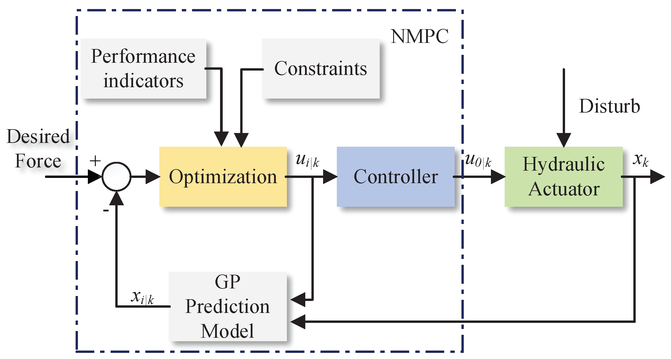
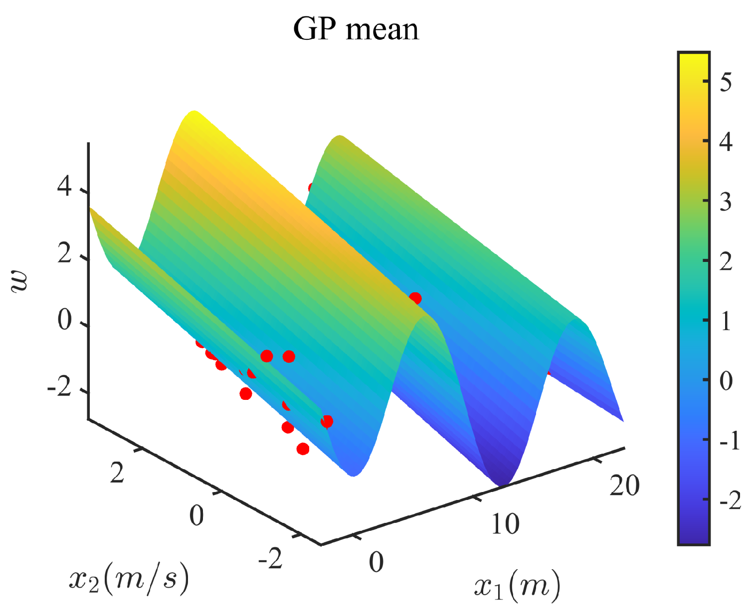
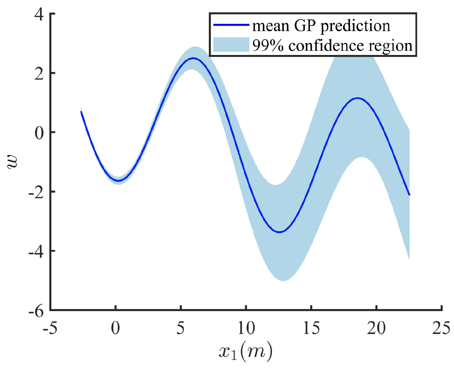
3.2. Model Predictive Control with Gaussian Process Uncertainty Models

In this section, we compensate for the impact of model adaptation on closed-loop control performance by GP learning state and input-related uncertainties. To simplify the representation, we assume that each dimension of w is learned separately. At each moment, the GP model evaluates the linearization error. Our goal is to solve the closed-loop MPC problem of the hydraulic position control system with uncertainty. Every N sampling times, the GP model evaluates a random distribution of w, which is added to the process noise, and then propagated forward through the predictive model. The resulting closed-loop MPC problem is formulated as
min U ( k ) J k = E k = 0 N 1 l ( x ( k ) , u ( k ) ) + F ( x ( N ) ) s . t . x ( k + 1 ) = f ( x ( k ) , u ( k ) ) + w ( k ) u j min u j ( k ) u j max , j = 1 , , m Δ u j min Δ u j ( k ) Δ u j max , j = 1 , , m x i min x i ( k ) x i max , i = 1 , , n
where J k is the cost function. The decision variable is defined by a series of control laws on the prediction range N. l ( x ( k ) , u ( k ) ) = x ( k ) T Q x ( k ) + u ( k ) k R u ( k ) denotes the utility function. F ( x ( N ) ) = x ( N ) T P x ( N ) is the terminal cost function. E is the expectation related to the uncertainty w ˜ in the hydraulic system, where w ˜ i : = d ( x i , u i ) + w i is the overall source of uncertainty at predicted time step i. Intuitively, this means that using GP to approximate the uncertainty in the system can greatly improve control performance. The reliability when using GP is discussed in [36].
With the Bellman optimal principle, J k can be rewritten as:
J k * = min U ( k ) l ( x ( k ) , u ( k ) ) + J k + 1 * ( x ( k + 1 ) )
The optimal control u * ( k ) can be obtained by minimizing (23):
u * ( k ) = arg min u ( k ) l ( x ( k ) , u ( k ) ) + J k + 1 * ( x ( k + 1 ) )
Because the hydraulic system has strong nonlinearities, which makes the closed-loop MPC problem unable to be solved directly. In order to obtain good stability performance and static and dynamic quality of nonlinear systems, the state feedback accurate linearization method in nonlinear control system theory has become a powerful tool for processing nonlinear systems. Although this can improve the tractability of the problem, it is a sub-optimal option and may cause the uncertainty forecast to grow substantially over time. Therefore, we use GP online optimization to define the function of the feedback strategy to improve the performance of the system.
We hope to quantify the uncertainty in the model through GP and weigh the coverage of uncertainty space and computational cost. Because of the GP model used to approximate equipment model mismatch, we use confidence intervals to characterize the expected range of uncertainty. From the previous analysis, we can obtain the following GP-MPC problem, which is formulated as [34]:
min U ( k ) J k = F ( μ N x , Σ N x ) + k = 0 N 1 l ( μ k x , μ k u , Σ k x ) s . t . μ k + 1 x = f ( μ k x , μ k u ) + μ k w Σ k + 1 x = f ( μ k x , μ k u ) I Σ k f ( μ k x , μ k u ) I T μ 0 x x ( k ) Σ 0 x = 0
for k = 0 , , N 1 . The optimal control law m u 0 u * is obtained by solving by solving for (25). m u 0 u * is the first element of the optimal control sequence μ 0 u * , , μ N u * .

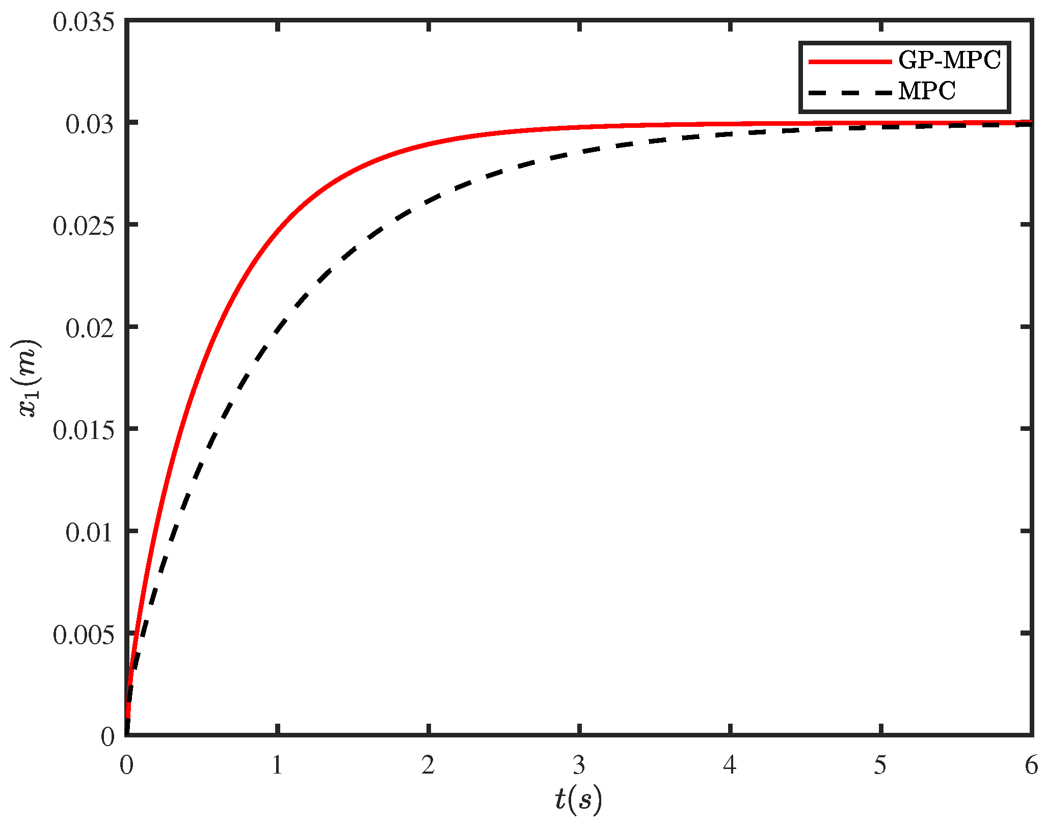
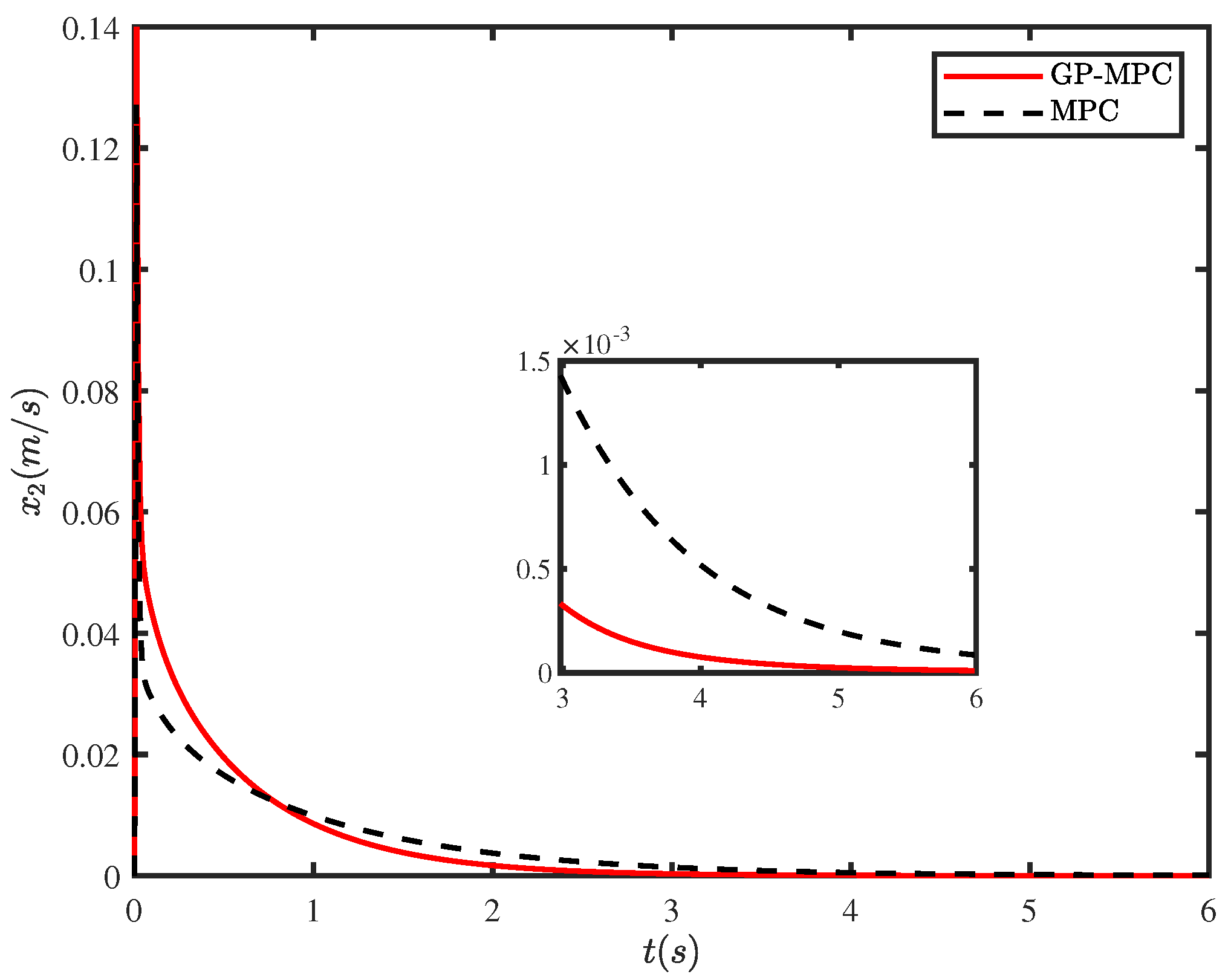
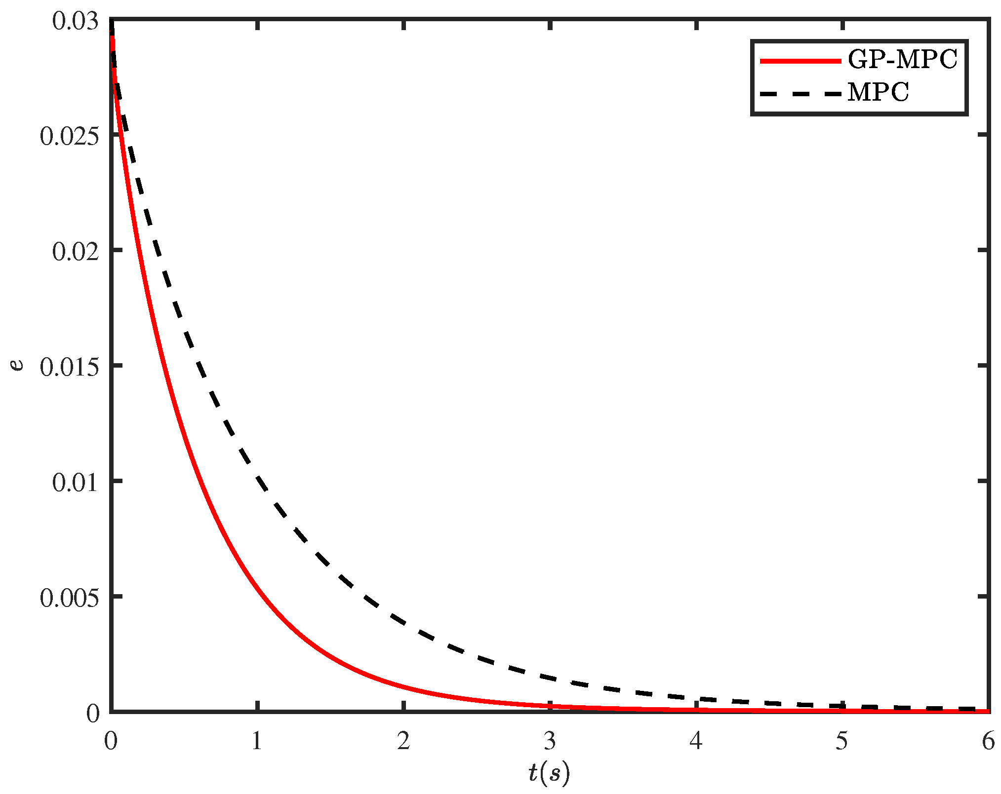
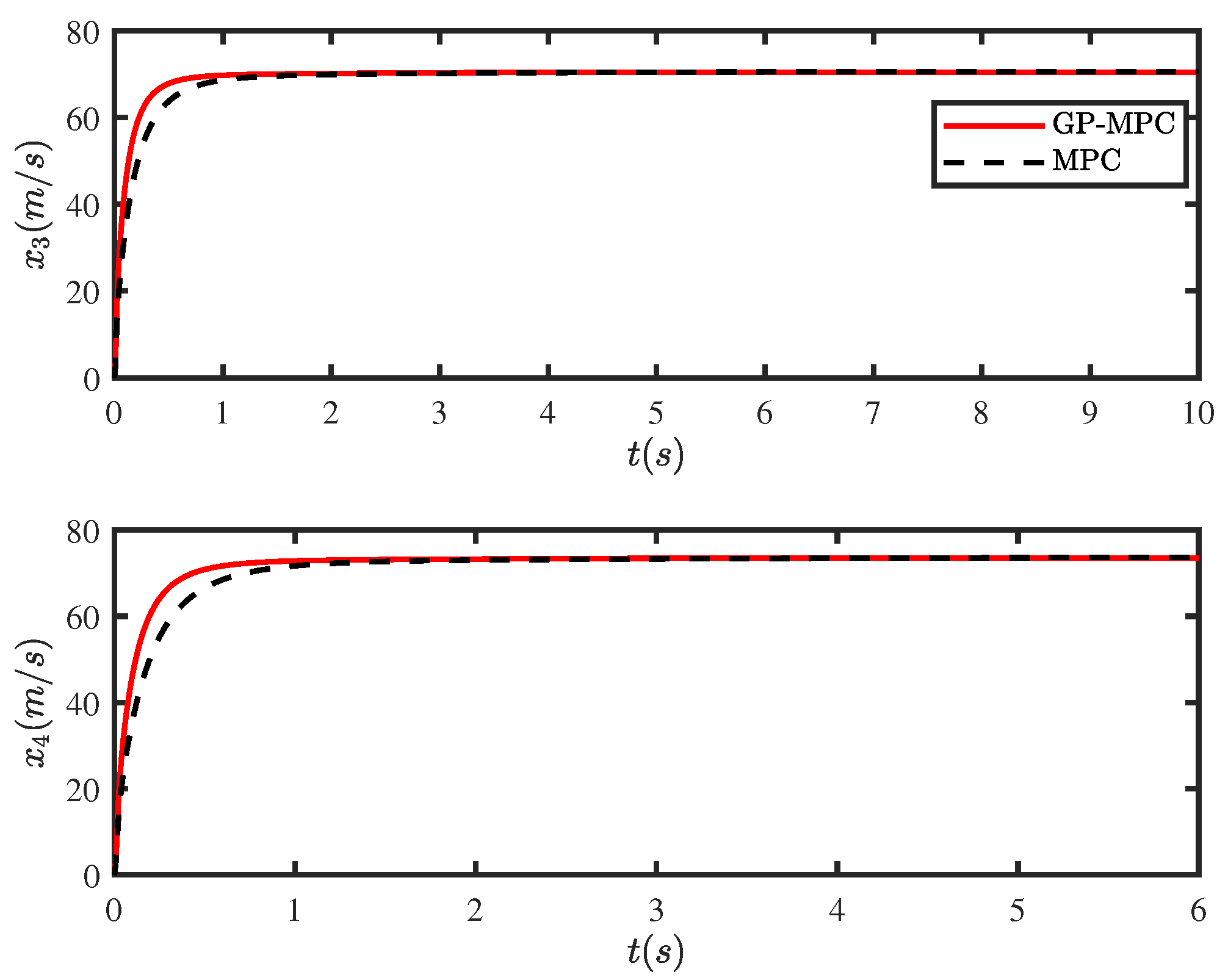
4. Results and Discussion

The control target is the position control in the hydraulic system to ensure that the system has no overshoot and high accuracy. The hydraulic system has 4 outputs x 1 , x 2 , x 3 , x 4 , and only one input u 1 is available. The hydraulic system is reorganized into two subsystems, namely the disturbance subsystem system and the nominal system. At the same time, the displacement movement is directly controlled by the solenoid valve. x 1 = y is the output of the hydraulic system, that is, the displacement of the mass block, and its position information can be measured by a position sensor. The input u 1 generated by the developed MPC controller is a known item, but because the system is subject to external interference, it is necessary to quantify its uncertainty through Gaussian process learning.
A continuous-time nonlinear mathematical model with control voltage and external load force input, piston position output, and Gaussian white noise is developed to test the effectiveness of the control algorithm. The relevant technical parameters are shown in Table 1.
Considering the movement of the hydraulic cylinder at any position, we establish the no-overshoot output constraint:
0 y * ( k + u ) r ( k + u ) , y ( k ) r ( k ) r ( k + u ) y * ( k + u ) 0.3 , y ( k ) r ( k )
In order to realize that the spool of the solenoid valve does not change the direction when working, an input is established as a constraint:
0 u 1 , y ( k ) r ( k ) 1 u 0 , y ( k ) r ( k )
From Figure 4, Figure 5 and Figure 6, the mean square error of the test set to output and the actual standard deviation of the output noise is computed. The GP regression training model may be used to get the 99% confidence region of the projected output value. The projected output’s noise level is accurately assessed.
Due to the different dimensions of the input features, the difference between the values is too large. In order to improve the model training accuracy, the input features are normalized with zero mean. The processed feature data have a mean value of 0 and a variance of 1, and the training set input samples are:
X = x 1 x ¯ x σ x , , x N x ¯ x σ x
where x ¯ x is the training set sample mean vector R 4 , σ x is the training set sample standard deviation vector R 4 . The test set input samples also need to use x ¯ x and σ x for normalization. The output features are used for model predictive control without normalization.
The closed-loop control of the position of the piston rod of the hydraulic cylinder after the added controller is carried out through the simulation experiment of the valve-controlled cylinder system. The control signal is given to the solenoid valve through the controller, so that the pressure difference between the two chambers of the hydraulic cylinder is controlled to control the movement of the piston rod of the hydraulic cylinder. We carry out simulation research on the control effect.
In a control system, it is usually desired that the change of the actual output of the system can be controlled freely, that is, the reference trajectory of the system output is set, so that the actual output of the system can track the set reference trajectory.
We set the noise signal w N ( 0 , 0.01 ) as small noise, because the noise signal will seriously affect the control effect of the system, and under excessive noise, the system may not be able to control. Therefore, a small noise signal is first selected here to illustrate the effectiveness of the model predictive control algorithm based on the Gaussian process. We set the prediction step size to N p = 16 and the control step size to N u = 5 . The control step size will determine the size of the derivation matrix in the MPC controller.
It can be seen from Figure 7 that the GP-MPC controller can accurately control the arrival of the nonlinear system to the reference unknown position at 2.5 s, which meets the basic requirements of control and also has high robustness. From the response speed of the valve control system, it can be clearly seen from the beginning of the simulation that the performance of GP-MPC is better than MPC.
It can be seen from Figure 8 that the speed curves of GP-MPC and MPC are very close in waveform and amplitude, but the GP model has better performance in noise processing, and the effect of GP-MPC is better. The oscillation of GP-MPC is more severe in the very small period of tracking time. It can be seen from Figure 5 and Figure 6 that the GP model can effectively reduce the noise, so that the controller can obtain a more stable control signal.
Through the experimental results, it is proved that the designed control method of the GP-MPC controller has high precision and fast response speed for the position control of the extension rod of the hydraulic cylinder. Due to the existence of various interferences in the actual process and the existence of certain deviations between the valve-controlled cylinder experimental system and the established mathematical model, the simulation results are not consistent with the experimental results. It can be seen from the experimental results in Figure 7, Figure 8, Figure 9 and Figure 10 that the designed control method has a good effect on the position control of the piston rod of the hydraulic cylinder.

5. Conclusions

This paper investigated the position control of a valve-controlled cylinder hydraulic system for ship steering gear. A nonlinear mathematical model for a valve-controlled cylinder hydraulic system was established. In order to solve the problem, the controlled object does not match the valve-controlled cylinder model. An MPC controller based on GP online learning to correct the model mismatch was designed. The GP model was obtained from the training dataset for estimating the standard deviation of the noise in the position increments. The output error of the system was adopted to adjust the prediction model. The results show that the GP-MPC control algorithm has better precision than the classical MPC control algorithm in position control of the steering gear hydraulic system. The position accuracy reached 0.1 mm, and the adjustment time is approximately 25% less than the classical MPC algorithm. In addition, the GP-MPC controller can accurately control the cylinder to unknown reference position in the case of mixed Gaussian white noise within 2.5 s, which shows strong robustness. This work establishes the model of the valve-controlled cylinder without considering the influence of the pipeline. In the actual operation process, the dynamic characteristics of the hydraulic pipeline will bring changes to the system structure. Therefore, the future work will add the pipeline model to discuss the stability and reliability of the proposed algorithm.

Author Contributions

Conceptualization, methodology, writing—original draft preparation, investigation, X.T.; validation, formal analysis, writing—review and editing, C.W.; writing—review and editing, supervision, X.X. All authors have read and agreed to the published version of the manuscript.

Funding

This research received no external funding.

Data Availability Statement

Data available on request from the authors.

Conflicts of Interest

The authors declare no conflict of interest.

Abbreviations

The following abbreviations are used in this manuscript:
LB-NMPCLearning Based Nonlinear Model Predictive Controller
MPCModel Predictive Controller
GPGaussian process
PIDProportional Integral Derivative
FLCFuzzy logic control
SVMSupport vector machine

References

  1. Semini, C.; Tsagarakis, N.G.; Guglielmino, E.; Focchi, M.; Cannella, F.; Caldwell, D.G. Design of HyQ-a hydraulically and electrically actuated quadruped robot. IMechE Part I J. Syst. Control Eng. 2011, 225, 831–849. [Google Scholar] [CrossRef]
  2. Khamitov, A.; Swanson, J.; Van de Ven, J.; Severson, E.L. Modeling, Design, and Testing of a Linear Electric-Hydraulic Conversion Machine for Electrification of Off-Highway Vehicles. IEEE Trans. Ind. Appl. 2021, 57, 2449–2459. [Google Scholar] [CrossRef]
  3. Mao, Z.; Tao, R.; Chen, F.; Bi, H.; Cao, J.; Luo, Y.; Fan, H.; Wang, Z. Investigation of the starting-up axial hydraulic force and structure characteristics of pump turbine in pump mode. J. Mar. Sci. Eng. 2021, 9, 158. [Google Scholar] [CrossRef]
  4. Palma, G.; Mizar Formentin, S.; Zanuttigh, B.; Contestabile, P.; Vicinanza, D. Numerical simulations of the hydraulic performance of a breakwater-integrated overtopping wave energy converter. J. Mar. Sci. Eng. 2019, 7, 38. [Google Scholar] [CrossRef] [Green Version]
  5. Wu, J.B.; Li, L.; Yan, Y.K.; Wang, P.J.; Wei, W. An Energy-Saving Position Control Strategy for Deep-Sea Valve-Controlled Hydraulic Cylinder Systems. J. Mar. Sci. Eng. 2022, 10, 567. [Google Scholar] [CrossRef]
  6. Sliwinski, P. The methodology of design of axial clearances compensation unit in hydraulic satellite displacement machine and their experimental verification. Arch. Civ. Mech. Eng. 2019, 19, 1163–1182. [Google Scholar] [CrossRef]
  7. Chiang, M.H.; Chen, C.C.; Kuo, J. The high response and high efficiency velocity control of a hydraulic injection molding machine using a variable rotational speed electro-hydraulic pump-controlled system. Int. J. Adv. Manuf. Technol. 2009, 43, 841–851. [Google Scholar] [CrossRef]
  8. Chrouta, J.; Chakchouk, W.; Zaafouri, A.; Jemli, M. Modeling and Control of an Irrigation Station Process Using Heterogeneous Cuckoo Search Algorithm and Fuzzy Logic Controller. IEEE Trans. Ind. Appl. 2019, 55, 976–990. [Google Scholar] [CrossRef]
  9. Kumari, R.; Prabhakaran, K.K.; Desingu, K.; Chelliah, T.R.; Sarma, S.V.A. Improved Hydroturbine Control and Future Prospects of Variable Speed Hydropower Plant. IEEE Trans. Ind. Appl. 2021, 57, 941–952. [Google Scholar] [CrossRef]
  10. Wang, C.N.; Yang, F.C.; Nguyen, V.T.T.; Vo, N.T.M. CFD Analysis and Optimum Design for a Centrifugal Pump Using an Effectively Artificial Intelligent Algorithm. Micromachines 2022, 13, 1208. [Google Scholar] [CrossRef]
  11. Liu, S.; Yao, B. Automated onboard modeling of cartridge valve flow mapping. IEEE/ASME Trans. Mechatronics 2006, 11, 381–388. [Google Scholar]
  12. Song, L.; Bin, Y. Coordinate Control of Energy Saving Programmable Valves. IEEE Trans. Control. Syst. Technol. 2008, 16, 34–45. [Google Scholar]
  13. Yao, J.; Jiao, Z.; Ma, D. Extended-State-Observer-Based Output Feedback Nonlinear Robust Control of Hydraulic Systems with Backstepping. IEEE Trans. Ind. Electron. 2014, 61, 6285–6293. [Google Scholar] [CrossRef]
  14. Jianyong, Y.; Zongxia, J.; Dawei, M. A Practical Nonlinear Adaptive Control of Hydraulic Servomechanisms With Periodic-Like Disturbances. IEEE/ASME Trans. Mechatron. 2015, 20, 2752–2760. [Google Scholar]
  15. Xu, X.; Chen, H.; Lian, C.; Li, D. Learning-Based Predictive Control for Discrete-Time Nonlinear Systems With Stochastic Disturbances. IEEE Trans. Neural Netw. Learn. Syst. 2018, 29, 6202–6213. [Google Scholar] [CrossRef]
  16. Nguyen, T.; Huynh, T.; Vu Ngoc, C.; Kieu, V.; Huang, S.C. Optimizing compliant gripper mechanism design by employing an effective bi-algorithm: Fuzzy logic and ANFIS. Microsyst. Technol. 2021, 27, 1–24. [Google Scholar] [CrossRef]
  17. Mozaffari, A.; Vajedi, M.; Azad, N.L. A robust safety-oriented autonomous cruise control scheme for electric vehicles based on model predictive control and online sequential extreme learning machine with a hyper-level fault tolerance-based supervisor. Neurocomputing 2015, 151, 845–856. [Google Scholar] [CrossRef]
  18. Giraldo, S.A.C.; Flesch, R.C.C.; Normey-Rico, J.E.; Sejas, M.Z.P. A Method for Designing Decoupled Filtered Smith Predictor for Square MIMO Systems with Multiple Time Delays. IEEE Trans. Ind. Appl. 2018, 54, 6439–6449. [Google Scholar] [CrossRef]
  19. Qi, F.; Stippich, A.; Ralev, I.; Klein-Hessling, A.; De Doncker, R.W. Model Predictive Control of a Switched Reluctance Machine for Guaranteed Overload Torque. IEEE Trans. Ind. Appl. 2019, 55, 1321–1331. [Google Scholar] [CrossRef]
  20. Ostafew, C.J.; Schoellig, A.P.; Barfoot, T.D. Robust Constrained Learning-based NMPC enabling reliable mobile robot path tracking. Int. J. Robot. Res. 2016, 35, 1547–1563. [Google Scholar] [CrossRef]
  21. Xiong, Z.; Tao, J.; Zhang, F. A Model Predictive Control Strategy of Pump-controlled Asymmetric Cylinders Using State Estimation. J. Xi’an Jiaotong Univ. 2017, 51, 109–115. [Google Scholar]
  22. Yang, T.; Tao, J.; Qin, C. Model Predictive Control of Asymmetric Valve Control Hydraulic Cylinders Based on Support Vector Machine and Sequential Quadratic Programming Algorithm. J. Xi’an Jiaotong Univ. 2020, 54, 93–100. [Google Scholar]
  23. Deldar, M.; Izadian, A.; Vaezi, M.; Anwar, S. Modeling of a Hydraulic Wind Power Transfer Utilizing a Proportional Valve. IEEE Trans. Ind. Appl. 2015, 51, 1837–1844. [Google Scholar] [CrossRef] [Green Version]
  24. Karg, B.; Lucia, S. Learning-based approximation of robust nonlinear predictive control with state estimation applied to a towing kite. In Proceedings of the 2019 18th European Control Conference (ECC), Naples, Italy, 25–28 June 2019; pp. 16–22. [Google Scholar]
  25. Mehndiratta, M.; Kayacan, E. A constrained instantaneous learning approach for aerial package delivery robots: Onboard implementation and experimental results. Auton. Robot. 2019, 43, 2209–2228. [Google Scholar] [CrossRef]
  26. Aswani, A.; Gonzalez, H.; Sastry, S.S.; Tomlin, C. Provably Safe and Robust Learning-Based Model Predictive Control. Automatica 2013, 49, 1216–1226. [Google Scholar] [CrossRef]
  27. Busoniu, L.; De Bruin, T.; Tolic, D.; Kober, J.; Palunko, I. Reinforcement learning for control: Performance, stability, and deep approximators. Annu. Rev. Control 2018, 46, 8–28. [Google Scholar] [CrossRef]
  28. Datta, A.; Augustin, M.J.; Gupta, N.; Viswamurthy, S.R.; Gaddikeri, K.M.; Sundaram, R. Impact Localization and Severity Estimation on Composite Structure Using Fiber Bragg Grating Sensors by Least Square Support Vector Regression. IEEE Sens. J. 2019, 19, 4463–4470. [Google Scholar] [CrossRef]
  29. Bozorgi, A.M.; Gholami-Khesht, H.; Farasat, M.; Mehraeen, S.; Monfared, M. Model Predictive Direct Power Control of Three-Phase Grid-Connected Converters With Fuzzy-Based Duty Cycle Modulation. IEEE Trans. Ind. Appl. 2018, 54, 4875–4885. [Google Scholar] [CrossRef]
  30. Fairbank, M.; Li, S.; Fu, X.; Alonso, E.; Wunsch, D. An adaptive recurrent neural-network controller using a stabilization matrix and predictive inputs to solve a tracking problem under disturbances. Neural Netw. 2014, 49, 74–86. [Google Scholar] [CrossRef] [Green Version]
  31. Karg, B.; Lucia, S. Efficient representation and approximation of model predictive control laws via deep learning. IEEE Trans. Cybern. 2020, 50, 3866–3878. [Google Scholar] [CrossRef]
  32. Park, J.; Sandberg, I. Universal Approximation Using Radial-Basis-Function Networks. Neural Comput. 2014, 3, 246–257. [Google Scholar] [CrossRef]
  33. Bonzanini, A.D.; Paulson, J.A.; Makrygiorgos, G.; Mesbah, A. Fast approximate learning-based multistage nonlinear model predictive control using Gaussian processes and deep neural networks. Comput. Chem. Eng. 2021, 145, 107174. [Google Scholar] [CrossRef]
  34. Hewing, L.; Wabersich, K.P.; Menner, M.; Zeilinger, M.N. Learning-Based Model Predictive Control: Toward Safe Learning in Control. Annu. Rev. Control. Robot. Auton. Syst. 2020, 3, 269–296. [Google Scholar] [CrossRef]
  35. Hongbo, G.; Yongtao, S.; LI Lei, e.a. Nonlinear Modeling and Validation of Hydraulic Valve-controlled Cylinder Power Mechanism. Mach. Des. Manuf. Engeering 2018, 47, 95–98. [Google Scholar]
  36. Meng, F.; Shen, X.; Karimi, H.R. Emerging methodologies in stability and optimization problems of learning-based nonlinear model predictive control: A survey. Int. J. Circuit Theory Appl. 2022, 50, 4146–4170. [Google Scholar] [CrossRef]
Figure 1. Electro-hydraulic servo system model diagram.
Jmse 10 02033 g001
Figure 2. Principle diagram of valve-controlled asymmetrical cylinder system.
Jmse 10 02033 g002
Figure 3. The force control loop of hydraulic system based on LB-NMPC. The Gaussian process is used to correct the model mismatch online. Due to the enormous computational complexity it brings, we use a support vector machine to approximate the NMPC control law.
Jmse 10 02033 g003
Figure 4. Gaussian process mean, kernel = Square exponent.
Jmse 10 02033 g004
Figure 5. Gaussian process standard deviation, kernel = Square exponent.
Jmse 10 02033 g005
Figure 6. Gaussian process prediction confidence.
Jmse 10 02033 g006
Figure 7. Position control under different strategies.
Jmse 10 02033 g007
Figure 8. The speed under different control strategies.
Jmse 10 02033 g008
Figure 9. Displacement control error of GP-MPC and MPC.
Jmse 10 02033 g009
Figure 10. Pressure of hydraulic system under different control strategies.
Jmse 10 02033 g010
Table 1. Basic parameters of system.
ParametersSpec
Mass of load100 kg
Piston diameter0.12 m
Rod diameter0.025 m
Length of stroke1 m
Dead volume at port 1 end0.00005 m 3
Dead volume at port 2 end0.00005 m 3
Valve rated current40 mA
Valve natural frequency80 Hz
Characteristic flow rate at maximum opening80 L/min
Pressure drop10 bar
Publisher’s Note: MDPI stays neutral with regard to jurisdictional claims in published maps and institutional affiliations.

