Article

Hybrid Modeling and Simulation for Shipboard Power System Considering High-Power Pulse Loads Integration

Department of Automation, Jiangsu University of Science and Technology, Zhenjiang 212100, China
*
Author to whom correspondence should be addressed.
J. Mar. Sci. Eng. 2022, 10(10), 1507; https://doi.org/10.3390/jmse10101507
Submission received: 24 August 2022 / Revised: 6 October 2022 / Accepted: 14 October 2022 / Published: 16 October 2022
(This article belongs to the Special Issue Smart Control of Ship Propulsion System)

Abstract

:
The complex dynamic characteristics of a shipboard power system (SPS) are not only related to its continuous dynamics but also influenced by discrete control behavior. Especially, during combat mission execution of high-power pulse loads (HPPLs), their operation plan as a sequence of discrete control events will cause successive abrupt changes in the continuous dynamics of SPS due to the sudden and intermittent nature of the external attacks, which requires overall comprehension of the hybrid dynamics evolution process driven by discrete events. In this paper, considering the zonal distribution structure of SPS and the influences of extreme events on the discrete dynamics of each zone, the extended hybrid models for each zone, including normal operation configuration and fault configuration, are obtained based on the hybrid automata theory. Then, the global hybrid model of SPS is developed. The mapping relationship of discrete state transition to the continuously controlled system is analyzed to reconstruct the set of differential equations model of the continuous system for the purpose of simulation. Two case studies are carried out to perform the simulation under the proposed hybrid model. It is demonstrated that this proposed method can reveal the operating characteristics of the hybrid dynamic evolution process driven by discrete events, both in normal operation and pulse loads operation. Although the precise measure of discrete states of SPS can be challenging to obtain, especially during the confrontation phase, the proposed method still provides valuable insights on evaluating the sophisticated dynamics of an SPS.

1. Introduction

The integrated power system of ships has become the main development direction of future ships, which can supply power to various loads on board, including daily electrical loads, maneuvering systems, communication, navigation, and propulsion systems [1,2]. Compared with conventional ships, a shipboard power system (SPS) can significantly reduce life-cycle costs, support more payloads, and provide greater survivability. By centralizing the propulsion system and other electrical equipment into a unified grid, SPS can rationally distribute energy throughout the ship. This will enable “unlocking” of propulsion energy and provide opportunities for high-powered pulsed loads (HPPLs, e.g., electromagnetic catapults, high-energy radars, and laser weapons) to be used on board, which will fundamentally transform the weaponry and significantly improve the maritime countermeasures capability of naval vessels [3,4,5].
The main purpose of HPPLs on board is to perform countermeasures [6,7]. External attacks are sudden and intermittent, and SPS also has the capability to actively combat extreme events. This means that the entire countermeasure process does not stop until the end of the event or the system is compromised. Random arrival of multiple concurrent attacks and fluctuating pulse loads during intense attack and defense will have a dramatic impact on SPS dynamics, making it difficult to build a system model that can characterize the entire operation of the confrontation.
Taking the electromagnetic rail gun (EMRG) as an example, the single launch duration is about 9ms, and the power demand is 160 MJ [8]. With the continuous demand (12/min) that must occur in the fierce confrontation process, such significant power must be provided by SPS. To reduce the impact of instantaneous ultra-high-power demand, energy storage devices should be used before HPPLs integration, such as batteries, supercapacitors, flywheels, and other hybrid energy storage devices [9,10,11].
However, the uncertainty of the countermeasure process and the complexity of the countermeasure target will cause the dynamic characteristics of SPS to change drastically in a short period of time, and the traditional system model can no longer meet the demand of real-time countermeasure decisions. In order to deal with multiple concurrent attacks arriving randomly and pulse-load operation plans for combating external targets, a model that can describe the system’s mixed dynamic evolution process driven by random discrete events in a holistic manner is required.
In addition, the zonal power distribution structure of SPS allows each zone to handle an external attack autonomously, and the damage caused by the attack will not spread beyond the damaged zone, which also determines that the system hybrid dynamic model must take into account the need for distributed control and provide a model basis for subsequent defense and recovery strategies. These are difficult to achieve by traditional modeling theory, simulation, and controller design.
The current research on modeling and simulation of SPS mainly focuses on continuous dynamic electromagnetic transient modeling and simulation methods [12,13,14]. High-accuracy models for medium-voltage DC (MVDC) SPS were developed to accurately capture the complex and nonlinear system continuous dynamics in physical test systems [15,16,17]. Attempts to use reduced-order models have also appeared in the study of AC ship integrated power systems [18,19] and in the authors’ previous work for MVDC SPS [20]. To minimize the computational time, a mixed SPS model using different component models with varying fidelity was established based on the bond graph method [21]. However, modeling and simulation studies that comprehensively consider the evolution of the mixed dynamics of SPS are still rarely addressed.
Some studies of power electronic systems proposed discrete-state event-driven hybrid models and simulation methods to analyze the multi-timescale mixing characteristics of power electronic systems [22,23,24]. However, these studies consider discrete events triggered by the evolution of the system’s own state, which is quite different from the external discrete attack events that SPS must actively respond to during a countermeasure.
Basically, hybrid modeling methods can be divided into two categories:
The first type considers the system as a continuous dynamic system and describes the whole system using differential equations. Events that make system equations change are used as discrete inputs, which means embedding the discrete events into the continuous dynamic system. This kind of method focuses on the stability and controllability of the system, and its main modeling methods are switching system model, hybrid logic dynamic model, etc. For example, a microgrid switching system model was established to ensure stability of microgrids in different operating states [25]. An AC/DC hybrid system switching system model was established and applied to the field of power system transient stability assessment [26]. The hybrid logic dynamic model was used to study the economic dispatch problem [27].
The second type is to embed continuous dynamic behavior into discrete event dynamic systems, focusing on performance verification and comprehensive design of controllers, whose main modeling methods are the hybrid automaton model, hybrid Petri net model, etc. The Petri net model was used to deal with the discrete switching control events in smart microgrids [28], and this model was also used to analyze the reachability of microgrids consisting of green energy sources [29]. A discrete hybrid automaton was used to model the storage system and controllable electrical loads of the UFES pilot microgrid [30].
While research efforts have been undertaken to study SPS as a hybrid system, the focus was prioritized to studying operations such as load shedding [31] and supervisory control [32]. For example, an equation of state model with integer inequality constraints was developed by building a hybrid logic dynamic model to analyze the optimal control behavior of SPS after loss of a generator [33]. However, this method always requires coarse discretization of the continuous state, and a large set of differential equations must be solved in the search space formed by the discretized continuous and discrete states at each moment, which is not suitable for describing the dynamic characteristics of SPS driven by a sequence of discrete events with drastic sudden changes in a short period of time. Moreover, it also cannot meet the needs of the subsequent defense and recovery strategy optimization considering accuracy and computational efficiency.
In the authors’ previous work, a centralized hybrid automaton model for the whole SPS was established for reconfiguration [34], and it was further extended to the model under partial observation in Ref. [35]. In this paper, we would like to continue the previous research by developing a distributed, hybrid model for SPS considering HPPLS integration, which not only provides a complete description of the system dynamics but also accommodates the requirements for zonal autonomy. A hybrid automaton model of SPS including both continuous and discrete dynamics of the system is established to completely describe the system dynamics. The simulation process of the hybrid model is divided into an iterative forward process: differential equations solving of the continuous controlled system in the discrete state, differential equations reconstruction of the continuous controlled system after discrete state transition and initial status resetting, and differential equations solving after the transfer. The implementation steps and algorithms of this process are provided. Further, two case studies are provided to show the SPS hybrid dynamic evolution process driven by discrete events.
Compared with the existing SPS modeling and simulation approaches, the novelty and intellectual merits of this paper can be summarized as follows:
(1)
This paper seeks a hybrid model for shipboard power systems considering high-power pulse loads integration, which can deal with multiple concurrent extreme events arriving randomly and fluctuating pulse-load operation, to illustrate the hybrid dynamic evolution process of SPS.
(2)
This paper presents the hybrid model in a distributed manner. The proposed model takes full advantage of the zonal distribution structure of SPS and allows each zone in SPS to handle the external events autonomously.
(3)
The proposed hybrid model provides a direct input/output interface to be integrated with different-scale continuous models, which allows easy refinement and adjustment to adapt to different ship design intentions and control requirements.
The rest of this paper is organized as follows. Section 2 introduces a representative MVDC SPS and derives its hybrid model description, while Section 3 illustrates the simulation process for this hybrid model. The simulation results are presented in Section 4, followed by the conclusions.

2. Hybrid Model Description for SPS

Based on the theory of hybrid automata, a hybrid model of SPS consisting of four zones is proposed in this section. The continuous dynamics of each zone are represented in the time domain by differential equations, and the continuous state reset relations caused by discrete state transition are provided to realize simulation of this hybrid model.

2.1. Representative SPS

The next-generation ship integrated power system proposed in Ref. [4], as shown in Figure 1, is provided as the baseline topology for this paper. This system consists of two main gas-turbine generator sets (MTGs) and two auxiliary gas-turbine generator sets (ATGs). These generator sets are connected to the port and starboard buses to form a zonal power distribution network connected at the bow and stern of the ship. This zonal distribution network supplies power to four kinds of loads: propulsion loads on each port and starboard side, consisting of the propulsion motor with its drive (variable speed drive, VSD) and propeller; inside the zonal network, there are three pulse loads connected to the port and starboard through energy storages; there are also four zonal loads representing the daily electrical loads of the ship, each of which is internally a small distribution network with a different internal structure depending on the actual needs of the ship. All generators and loads are connected to the distribution network through power conversion modules (PCM) and circuit breakers (black squares in the figure). It should be noted that, although there are connection switches for the port and starboard DC buses at the bow and stern of the ship, the port and starboard are normally operated separately.
The dotted lines connecting port and starboard breakers divide the entire SPS into four zones. The power supply devices (generator sets and energy storage equipment) are distributed among the zones and can supply power to the loads across the zones. The zonal distribution network allows each zone to be autonomous, and the damage caused by attacks does not spread beyond the damaged zone. Establishing separate hybrid models for each zone will facilitate implementation of subsequent distributed control schemes.

2.2. Automata-Based Hybrid Model for Each Zone

For each zone of SPS, its basic hybrid structure can include discrete controllers and continuous controlled systems and their interfaces, describing the discrete event dynamics and continuous dynamics, respectively. Its basic hybrid model can be represented by a hybrid automaton:
H = ( Q , X , Y , U , I n i t , f , g , Σ , E G , T , R )
where Q X is the state space, Q is finite, Y is the set of output variables, U is the set of continuous control inputs, I n i t Q × X × U is the set of initial conditions, f : Q × X × U X is the set of continuous state evolution laws describing the continuous state corresponding to each q Q , g : Q × X × Y × U Y is the set of algebraic equations for each q Q , Σ = Σ c Σ u is the set of discrete events, where Σ c is the set of controllable events, Σ u is the set of uncontrollable events, E G : X × U Σ is the event generator function, T : Σ × Q 2 Q is the discrete state transition relation, R : Q × X × U 2 X × U is the reset relation, that is, the control behavior generator function.
The impact of extreme events on the discrete dynamics of the zones is considered to develop an extended zonal hybrid model. The extreme events, i.e., external attacks, have two effects on the discrete dynamics of the zones: one is the intra-zone initiation of pulse loads, and the second is the fault caused by the attacks on the damage of each zone (including communication and cables, etc.). The former can be considered as the normal operation configuration of the zone, while the latter is the fault configuration, according to which the discrete event transfer of each zone is classified. The operational configuration of each zone is regarded as the set of normal operational configuration and fault configuration, and the set of transition events between the two configurations is defined. Then, we can obtain the extended hybrid model of each zone:
S = ( , F T , R E , H 0 )
where is the set of all possible configurations of the subsystem, S and H 0 is the initial configuration of the subsystem S . FT and RE are the set of transition events between the normal operation configuration and the failure configuration:
F T = { f t j i : i = 1 , 2 , , n ; j = 1 , 2 , , m }
R E = { r r j : r = 1 , 2 , , n ; j = 1 , 2 , , m }
where f t j i is the fault events, and r r j is the recovery events.
In this hybrid model, each discrete state of a zone has its corresponding differential equations to describe the continuous dynamics. Take zone 1 as an example: its continuous controlled dynamics in the discrete state q i can be expressed as:
x ˙ = f q i ( x q i , y q i , u q i ) 0 = g q i ( x q i , y q i , u q i )
The continuous dynamic modeling process for SPS can be found in a previous publication by the authors [28]. Here, we only provide the basic description of variables in (5), where x q i is the continuous state variables (including state variables of MTG, pulse load, DC bus voltage, and current, etc.), y q i is the output variables (including variables we want to monitor), and u q i is the continuous control inputs (including preset values for MTG and other device controllers inside zone 1). f q i and g q i are the differential functions that can be derived from Ref. [20].
For the discrete states in this model, let us express the online status of the MTG, ATG, PM, pulse load, and zonal load as integer values, as well as the connection status of breakers in the zone. The set of current states of all these devices is a discrete state in this hybrid model. In addition, take zone 1 as an example: it includes an ATG, two types of load, and a breaker connecting the port and starboard. We use “0”, “1”, “2”, and “3” to indicate the connection status of loads, with “0” indicating no connection, “1” indicating the connection to the starboard bus, and “2” indicating the connection to zone 2, and “3” indicating a simultaneous connection to port and starboard. Then, for ATG, indicators of “0” and “1” can be used to represent their online status, with “0” indicating offline and “1” indicating online. Moreover, for the breaker, “0” indicates open, and “1” indicates closed. Combining these indicators, we can use a string to express the discrete states of zone 1. For example, “1310” means that the ATG is online, the pulse load is connecting to the port and starboard simultaneously, the zone load is connecting to the starboard bus, and the breaker is open.
The discrete dynamics of a zone are represented by event-driven discrete state transitions, such as the discrete state transition of zone 1 from “1310” to “0130” is caused by the event “ATG shutdown”. With the transition of discrete states, not only the differential equations describing the continuous dynamics change but also the initial conditions after the transition must be recalculated. This will be discussed in Section 4.

2.3. Global Hybrid Model for SPS

Assume that there are s zones in the SPS (in this paper, it is 4), and the zone S k ( k = 1 , 2 , , 4 ) has ( n + m ) k configurations. Therefore, the distributed configuration of SPS can then be denoted by
C = ( H 1 , l 1 , H 2 , l 2 , , H s , l s )
where H k , l k is the zone configuration in , l k = 0 , 1 , , ( n + m ) k . The set of all possible distributed configurations of SPS can be denoted by C . Therefore, the global model for SPS can be represented as:
S = ( C , 0 )
where 0 is the initial distributed configuration of SPS.
This global hybrid model fully reflects the autonomous nature of each zone, where each zone can handle its own internal operation and management as well as respond to external attacks.

3. Hybrid Simulation Method for SPS

Simulation of the hybrid model involves the continuous dynamic mutation caused by a discrete state transition. Therefore, the simulation necessarily includes two steps: (1) calculating the initial conditions of the system after discrete state transition; (2) continuous dynamics simulation of the system in the discrete state after the transition.

3.1. Continuous Dynamic Mutation Due to Discrete State Transition

Suppose that system is first in a discrete state q i with differential equations as (8); after the discrete state transition occurs, the system is in q j and differential equations as (9):
x ( k + 1 ) = f q i ( x q i ( τ ) , y q i ( τ ) , u q i ( τ ) ) 0 = g q i ( x q i ( τ ) , y q i ( τ ) , u q i ( τ ) )
x ( k + 1 ) = f q j ( x q j ( τ + ) , y q j ( τ + ) , u q j ( τ + ) ) 0 = g q j ( x q j ( τ + ) , y q j ( τ + ) , u q j ( τ + ) )
where x ( τ + ) , y ( τ + ) , u ( τ + ) are continuous state variables, output variables, and continuous control inputs after discrete state transition, respectively.
The change in output variables and continuous state variables caused by discrete state transition, which is also the reset relationship of continuous state after discrete state transition, has the following initial condition calculation flow chart:
It should be noted that the numbers of output variables, continuous state variables, and control inputs may change after the discrete state transition. During the flow chart in Figure 2, the output variables are solved first, followed by the continuous state variables; after that, the continuous state variables at the end of time step k are calculated in normal order by using the following backward differencing method:
x q j ( k ) x q j ( τ + ) = h 2 ( f q j ( x q j ( k ) , y q j ( τ + ) , u q j ( k ) ) + f q j ( x q j ( τ + ) , y q j ( τ + ) , u q j ( τ + ) ) )
After the above steps, the system simulation can continue until another discrete state transition occurs.

3.2. Continuous Dynamic Model Reconstruction and Solving after Discrete State Transition

Basically, besides reformulating the differential equations of the system and resetting the initial conditions when the discrete state transition occurs, simulation of hybrid systems only requires solving the differential equations under the current discrete state.
First, differential equations set for each zone are formed by differential equations for all components in that zone with their input–output relationships. Detailed differential equations for each component can be found in Ref. [20], including the power generation module, propulsion module, power conversion module, energy storage module, loads, and power distribution module. These equations cover the parameters, state variables, control inputs, and outputs of each component. Based on the current discrete state of the zone, the operating status of each component is determined. Then, we can construct the differential equations for the zone by connecting the input–output relationships of these components based on the internal distribution network, as shown by f Z ( x , y , u ) in Figure 3.
Then, the global hybrid model can be formed by (7). In this paper, the proposed global hybrid model is a loosely distributed structure under weak restrictions. Each zone can execute its internal operations and calculate the continuous dynamics driven by discrete events. Figure 3 provides the inter-zone power flow relationships under the zonal distribution network. In this way, the hybrid model proposed here can be easily applied to further distributed control and management studies.
Finally, the generalized discretization method (fourth-order Runge–Kutta method) is used to solve the differential equations. The whole simulation is implemented in MATLAB platform.

4. Simulation and Results Analysis

In order to verify the hybrid modeling and simulation method proposed in this paper, a typical SPS shown in Figure 1 is used here to build a hybrid model and perform simulation cases. Table 1 displays the component specifications of the SPS under study, whose detailed parameters can be found in Ref. [28].
The discrete states of SPS are determined by the working status of all components and the connection status of power cables. Due to the large number of power cables in the system, here, we only provide the possible discrete states of all components in Table 2. The discrete status of the generator set indicates whether it is online or not. The propulsion motor can be offline or operating at 50% or rated power. The zonal load and pulse load can be disconnected or supplied by port, starboard, or both port and starboard equally. The port and starboard connecting breakers can be open or closed.

4.1. SPS Start-Up Scenario

First, consider the scenario where the ship starts up to full speed, which means that the final propulsion motor will run at its maximum power of 37 MW, and, with four zone loads, the full system load power is close to 80 MW. The discrete event sequences and their occurrence moments during the whole simulation are shown in Table 3. In addition, the operation of the pulsed load is not considered in this condition, and the EMRG will remain disconnected during the whole process.
The simulation results are shown in Figure 4, Figure 5, Figure 6, Figure 7, Figure 8 and Figure 9, which provide the full-system simulation results under the starting condition, including the mechanical torque and speed of the gas turbine, DC bus voltage, output current of the generator set, electromagnetic torque and speed of the propulsion motor output, ship’s speed and resistance, mechanical power output of the gas turbine, power output of the generator set, mechanical power output of the propulsion motor, and zonal loads power curves.
The simulation result curve shows that, from the initial moment to 20 s, the gas turbine is first started under the action of the governor, and its speed is gradually stabilized at the rated value of 377.0 rad/s. Meanwhile, the DC bus voltage rises continuously under the action of the generator excitation controller and remains stable when it reaches the rated value of 5000 V. At 20 s, the zonal loads are online; at this time, the power of the generator sets undergoes a small increase. At 30 s, the propulsion system is connected to the DC bus, and a given electromagnetic torque is added at a speed of 50,000 N·m/s. When the torque reaches 3MN·m, it remains stable. At this time, there is a significant increase in the output current of MTG, which causes a slight fluctuation in the DC bus voltage. The electromagnetic torque of the propulsion motor rises gradually with the given value, driving the propeller to rotate, and the propeller starts to produce resistance torque and thrust for the ship to sail forward. After the electromagnetic torque of the propulsion motor reaches stability, the rotational speed also gradually reaches stability, while the ship’s speed takes a longer time to stabilize due to the large inertia time constant, and it finally reaches 32 knots in about 200 s.

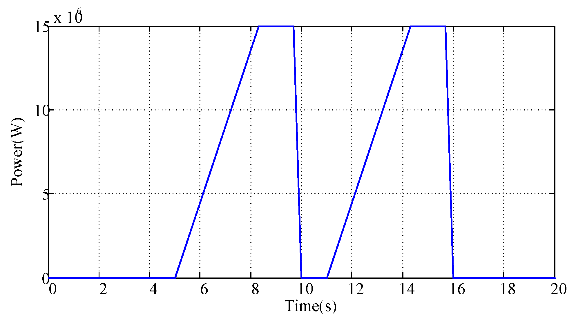
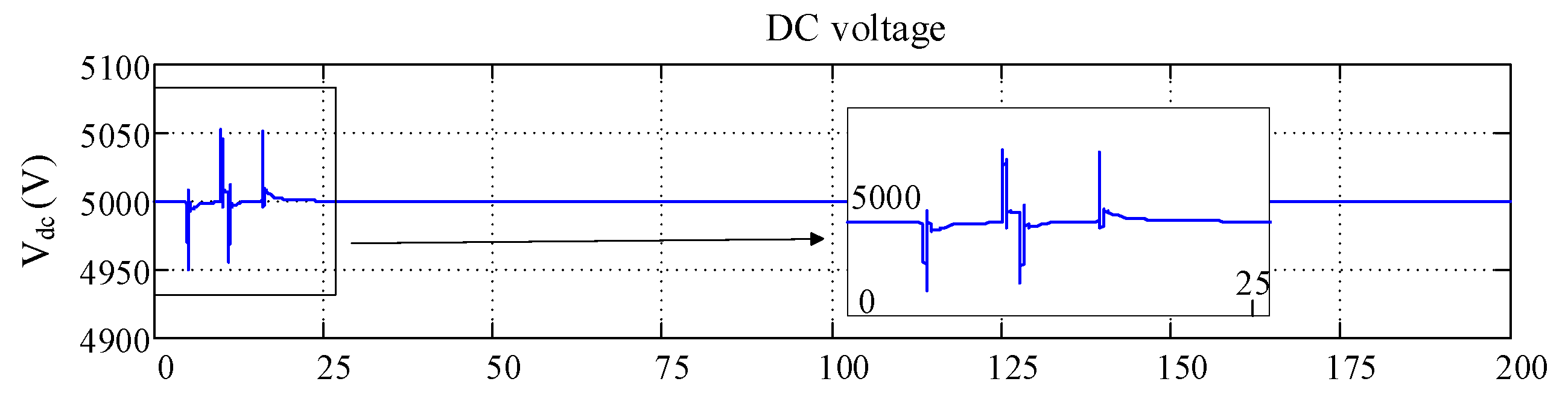
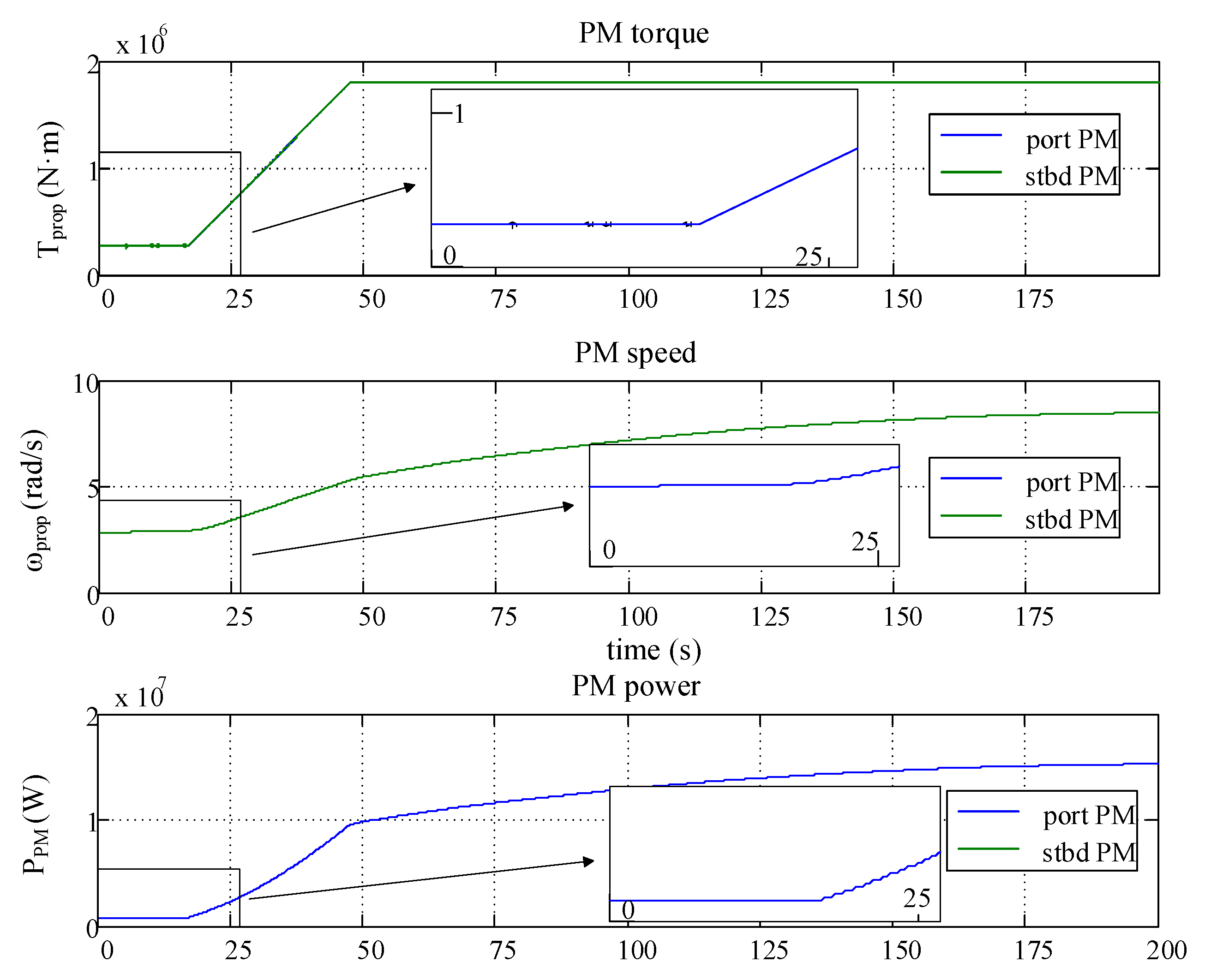
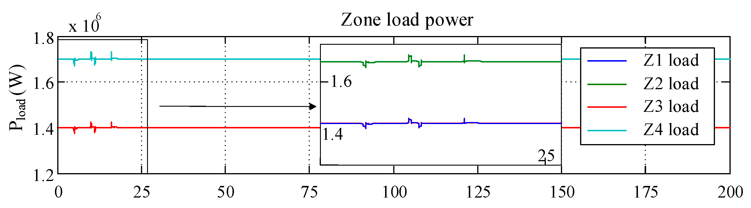
4.2. Pulse Load Launch Scenario

Next, consider the pulse load launch scenario. It should be noted that the pulse load of zone 1 in Figure 1 includes the energy storage module, which rises to 15 MW in 5 s and then performs pulse load firing with the whole pulse period of 6 s. This pulse load is powered by the port and starboard together. The pulse power curve is shown in Figure 10, whose load demand will rise to 15 MW in 3.33 s and fall at a rate of 50 MW/s. The discrete event sequence and its occurrence moment during the whole simulation are shown in the Table 4. The gas turbine is controlled by the governor to drive the synchronous generator to always run at a constant speed, and the zonal loads and radar are always kept online with an initial ship speed of 8 knots and accelerated to 25 knots after two launches. The simulation time is 200 s.
The simulation results are shown in Figure 11, Figure 12, Figure 13, Figure 14, Figure 15 and Figure 16. They also provide the mechanical torque and speed of the gas turbine, DC bus voltage, output current of the generator set, electromagnetic torque and speed of the propulsion motor output, ship’s speed and resistance, mechanical power output of the gas turbine, power output of the generator set, mechanical power output of the propulsion motor, and zonal loads power curves.
The simulation result curves show that the system is in a steady state at the beginning, at a speed of 8 knots. Before the launch of EMRG, the energy storage device absorbs and accumulates energy from SPS, and this energy is released for pulse load during the mission. In this case, during each pulse duration, the energy storage device is charged at 15 MW for 5 s and then discharged for 1 s as the EMRG is fired. With the launch of the pulse load in 5 s, there is a small oscillation in the speed of the gas turbine. After the pulse load is put into use, its power rises to 15 MW in 3.3 s. As seen from the output power curve of the generator set, there is a sharp rise in the output power of both MTGs to meet the load power. At the same time, the DC bus voltage drops. During the charging and discharging process of the pulse load, there are four oscillations in the DC bus voltage curve, but they all return to the set value quickly. Although it is not obvious in the simulation curve, the output power of the propulsion motor also shows a slight oscillation, which is directly related to the oscillation of the DC bus voltage. After the pulse load stops working, the ship enters an acceleration phase by adding a given electromagnetic torque at 25,000 N·m/s to reach 0.9 MN·m. The ship speed reaches 25 knots in about 200 s.

4.3. Comparison and Discussion

Our work presents a hybrid model architecture for SPS that focuses on the continuous dynamics triggered by discrete events transition. Benefiting from the properties of the hybrid model, SPS can be treated as a discrete event system by event and control action generation. Thus, this hybrid model can accept pulse loads operation plans as discrete event sequences and perform simulation and analysis. Other modeling methods can also be used for SPS simulation but may not be suitable for the following control and energy management requirements of SPS. As we emphasized in the introduction, multiple concurrent attacks arriving randomly and the pulse loads operation plan will cause the dynamic characteristics of SPS to change drastically in a short period of time, making it important to focus on the discrete event sequences and their impact on the dynamics in each zone. This is exactly the reason why we propose this hybrid model.
In the following discussion, different modeling methods are compared from five different aspects: application SPS topology, model type, configuration, method, and case studies. The results are shown in Table 5. It can be seen that most modeling studies do not take into account the distributed feature of SPS, and they are more concerned with computational efficiency. However, it is obvious that a distributed solution will be more economical in terms of computational resources. Additionally, previous hybrid model studies have tended to focus on system reconfiguration after components failed but have not considered the impact of external attacks. As we mentioned in the introduction, pulse loads operation plans and faults caused by external attacks will have a significant impact on system dynamics, which requires attention to system dynamics affected by discrete event sequences. Among the few hybrid modeling pieces of research for SPS in the literature, our work shows its advantages in distributed and pulse loads adaptability.

5. Conclusions

This paper proposes a hybrid modeling method for SPS that takes into account discrete control events and continuous system dynamics. In particular, considering HPPLs integration with discrete and random attack event sequences, the hybrid model of each zone is established separately according to the zonal power distribution structure, which enables dealing with external attack events and actual damage from the perspective of zone autonomy. Through continuous states reset after discrete state transition and reconstruction and solving of continuous differential equations, simulation of the SPS hybrid model is realized. The simulation results show that the hybrid model developed in this paper can specifically describe the hybrid dynamic evolution process of SPS driven by discrete events, as well as the operating characteristics of the whole process into the confrontation phase. This research can improve the modeling theory of SPS and enrich system analysis.
As an extension of our work, one can systematically investigate the effect of cyber failures on the onboard control and communication systems, which will cause abnormal operation of SPS and result in the unobservable state of some equipment. Especially during the confrontation phase, it is probable that the system state is partially observable. State estimates, as with our previous research in Ref. [35], can be further introduced to provide a prediction of system dynamics.

Author Contributions

Conceptualization, W.Z. and C.J.; methodology, W.Z.; validation, W.Z., C.J. and Z.L.; formal analysis, C.J.; writing—original draft preparation, W.Z.; writing—review and editing, W.Z.; project administration, W.Z. All authors have read and agreed to the published version of the manuscript.

Funding

This research was funded by Foundation of National Defense Science and Technology Key Laboratory, grant number 6142217200307.

Institutional Review Board Statement

Not applicable.

Informed Consent Statement

Not applicable.

Data Availability Statement

Not applicable.

Conflicts of Interest

The authors declare no conflict of interest.

References

  1. Chalfant, J.S.; Chryssostomidis, C. Analysis of various all-electric-ship electrical distribution system topologies. In Proceedings of the 2011 IEEE Electric Ship Technologies Symposium, Alexandria, VA, USA, 10–13 April 2011; pp. 72–77. [Google Scholar] [CrossRef] [Green Version]
  2. Doerry, N.; McCoy, K. Next Generation Integrated Power System: NGIPS Technology Development Roadmap; No. SER-05D/349; Naval Sea Systems Command: Washington, DC, USA, 2007. [Google Scholar]
  3. Doerry, N. Naval Power Systems: Integrated power systems for the continuity of the electrical power supply. IEEE Electrif. Mag. 2015, 3, 12–21. [Google Scholar] [CrossRef]
  4. Doerry, N.; Amy, J. Design considerations for a reference MVDC power system. Proc. SNAME Marit. Conv. 2016, 124, 40–59. [Google Scholar]
  5. Zohrabi, N.; Shi, J.; Abdelwahed, S. An overview of design specifications and requirements for the MVDC shipboard power system. Int. J. Electr. Power Energy Syst. 2019, 104, 680–693. [Google Scholar] [CrossRef]
  6. Domaschk, L.N.; Ouroua, A.; Hebner, R.E.; Bowlin, O.E.; Colson, W.B. Coordination of Large Pulsed Loads on Future Electric Ships. IEEE Trans. Magn. 2007, 43, 450–455. [Google Scholar] [CrossRef] [Green Version]
  7. Clayton, D.H.; Jebsen, G.M.; Sofia, J.M. The All Electric Warship from Vision to Total Ship System Integration. Nav. Surf. Warf. Cent. Dahlgren Div. 2002, 86, 1–9. [Google Scholar]
  8. Smart, R.; Chalfant, J.; Herbst, J.; Langland, B.; Card, A.; Leonard, R.; Gattozzi, A. Using S3D to analyze ship system alternatives for a 100 MW 10,000 ton surface combatant. In Proceedings of the 2017 IEEE Electric Ship Technologies Symposium (ESTS), Arlington, VA, USA, 15–17 August 2017; pp. 96–103. [Google Scholar] [CrossRef]
  9. McCoy Timothy, J.; John, V. The state-of-the-art of integrated electric power and propulsion systems and technologies on ships. In Proceedings of the 2009 IEEE Electric Ship Technologies Symposium, Baltimore, MD, USA, 20–22 April 2009. [Google Scholar]
  10. Trinklein, E.H.; Parker, G.G.; McCoy, T.J. Modeling, optimization, and control of ship energy systems using exergy methods. Energy 2020, 191, 116542. [Google Scholar] [CrossRef]
  11. Weaver, W.W.; Robinett, R.D.; Wilson, D.G.; Matthews, R.C. Metastability of pulse power loads using the hamiltonian surface shaping method. IEEE Trans. Energy Convers. 2017, 32, 820–828. [Google Scholar] [CrossRef]
  12. Shi, J.; Amgai, R.; Abdelwahed, S. Modelling of shipboard medium-voltage direct current system for system level dynamic analysis. IET Electr. Syst. Transp. 2015, 5, 156–165. [Google Scholar] [CrossRef]
  13. Zahedi, B.; Norum, L.E. Modeling and Simulation of All-Electric Ships With Low-Voltage DC Hybrid Power Systems. IEEE Trans. Power Electron. 2013, 28, 4525–4537. [Google Scholar] [CrossRef]
  14. Shajari, Z.; Savaghebi, M.; Guerrero, J.M.; Javidi, M.H. Dynamic Performance Assessment of NG-MVDC Shipboard Power System with Distributed Electric Propulsions. In Proceedings of the 2020 IEEE Electric Power and Energy Conference (EPEC), Edmonton, AB, Canada, 14–16 October 2020; pp. 1–7. [Google Scholar] [CrossRef]
  15. Andrus, M. NGIPS MVDC Baseline Architecture Definition-RTDS Implementation. Center for Advanced Power Systems, Florida State University. 2010. Available online: https://www.esrdc.com/library (accessed on 23 August 2022).
  16. Lahiri, S. Modeling and Simulation of Shipboard Integrated Power Systems; Drexel University: Philadelphia, PA, USA, 2011. [Google Scholar]
  17. Skjong, S.; Pedersen, E. A real-time simulator framework for marine power plants with weak power grids. Mechatronics 2017, 47, 24–36. [Google Scholar] [CrossRef] [Green Version]
  18. Abdelwahed, S.; Asrari, A.; Crider, J.; Dougal, R.A.; Faruque, M.O.; Fu, Y.; Langston, J.; Lee, Y.; Mohammadpour, H.A.; Ouroua, A.; et al. Reduced order modeling of a shipboard power system. In Proceedings of the 2013 IEEE Electric Ship Technologies Sympo-sium (ESTS), Arlington, VA, USA, 22–24 April 2013; pp. 256–263. [Google Scholar] [CrossRef] [Green Version]
  19. Park, D.; Zadeh, M.K. Dynamic Modeling and Stability Analysis of Onboard DC Power System for Hybrid Electric Ships. In Proceedings of the 2019 IEEE Transportation Electrification Conference and Expo (ITEC), Novi, MI, USA, 19–21 June 2019; pp. 1–6. [Google Scholar] [CrossRef] [Green Version]
  20. Zhu, W.; Shi, J.; Abdelwahed, S. End-to-end system level modeling and simulation for medium-voltage DC electric ship power systems. Int. J. Nav. Archit. Ocean. Eng. 2018, 10, 37–47. [Google Scholar] [CrossRef]
  21. Ghimire, P.; Reddy, N.P.; Zadeh, M.K.; Pedersen, E.; Thorstensen, J. Dynamic Modeling and Real-Time Simulation of a Ship Hybrid Power System Using a Mixed-Modeling Approach. In Proceedings of the 2020 IEEE Transportation Electrification Conference & Expo (ITEC), Chicago, IL, USA, 22–26 June 2020; pp. 1–6. [Google Scholar] [CrossRef]
  22. Yang, Y.; Zhengming, Z.; Tan, T.; Boyang, L.; Liqiang, Y. Discrete State Event Driven Method and Self-Adapted Pre-dictor-Corrector Algorithm. Trans. China Electrotech. Soc. 2017, 32, 33–41. [Google Scholar]
  23. Bochen, S.; Zhengming, Z.; Yicheng, Z.; Zhujun, J. Discrete-state Event-driven Simulation Approach for Multi-time-scale Power Electronic Hybrid System. Proc. CSEE 2021, 41, 2980–2989. [Google Scholar]
  24. Khan, M.S.; Iravani, M.R. Supervisory Hybrid Control of a Micro Grid System. In Proceedings of the 2007 IEEE Canada Electrical Power Conference, Montreal, QC, Canada, 25–26 October 2007; pp. 20–24. [Google Scholar] [CrossRef]
  25. Sun, L.Y.; Zhang, P.F.; Lv, J.J. Design of Dual-mode Control for Microgrid Inverter Based on Switching System. Control. Eng. China 2021, 28, 1567–1579. [Google Scholar]
  26. Jiawei, H.; Tong, W.; Zengping, W.; Jiuliang, L.; Jingtian, B. Switching System’s MLE Based Transient Stability Assessment of AC/DC Hybrid System Considering Continuous Commutation Failure. IEEE Trans. Power Syst. 2021, 36, 757–768. [Google Scholar]
  27. Ke, C.; Yiguo, L.; Junli, Z.; Songlin, C.; Honghai, N.; Bing, L. Dynamic economic dispatch for CHP-MG system based on mixed logical dynamic model and MPC method. In Proceedings of the IEEE 2020 39th Chinese Control Conference (CCC), Shenyang, China, 27–29 July 2020; pp. 1630–1636. [Google Scholar]
  28. Chamorro, H.R.; Pazmino, C.; Paez, D.; Jimenez, F.; Guerrero, J.M.; Sood, V.K.; Martinez, W. Multi-agent Control Strategy for Microgrids using Petri Nets. In Proceedings of the 2020 IEEE 29th International Symposium on Industrial Electronics (ISIE), Delft, Netherlands, 17–19 June 2020; pp. 1141–1146. [Google Scholar] [CrossRef]
  29. Lu, X.; Zhou, M.; Ammari, A.C.; Ji, J. Hybrid Petri nets for modeling and analysis of microgrid systems. IEEE/CAA J. Autom. Sin. 2016, 3, 349–356. [Google Scholar] [CrossRef]
  30. Silva, D.P.; Queiroz, M.D.; Fardin, J.F.; Sales, J.L.F.; Orlando, M.T.D. Hybrid modeling of energy storage system and electrical loads in a pilot-microgrid. In Proceedings of the 2018 13th IEEE International Conference on Industry Applications (INDUSCON), São Paulo, Brazil, 11–14 November 2018; pp. 433–438. [Google Scholar] [CrossRef]
  31. Babaei, M.; Shi, J.; Zohrabi, N.; Abdelwahed, S. Development of a hybrid model for shipboard power systems. In Proceedings of the 2015 IEEE Electric Ship Technologies Symposium (ESTS), Alexandria, VA, USA, 21–24 June 2015; pp. 145–149. [Google Scholar] [CrossRef]
  32. Lahiri, S.; Niebur, D.; Kwatny, H.; Bajpai, G.; Beytin, A.; Patel, J.; Kang, R. A software tool for automated management and supervisory control of shipboard Integrated Power Systems. In Proceedings of the 2012 IEEE Power and Energy Society General Meeting, 22–26 July 2012; pp. 1–7. [Google Scholar] [CrossRef]
  33. Yasar, M.; Beytin, A.; Bajpai, G.; Kwatny, H.G. Integrated Electric Power System supervision for reconfiguration and damage mitigation. In Proceedings of the 2009 IEEE Electric Ship Technologies Symposium, Baltimore, MD, USA, 20–22 April 2009; pp. 345–352. [Google Scholar] [CrossRef]
  34. Zhu, W.; Liang, Z.; Zhu, Z.; Zhi, P. A Distributed Hybrid Control Framework for Shipboard Power System Reconfiguration. In Proceedings of the 2021 4th IEEE International Conference on Industrial Cyber-Physical Systems (ICPS), Victoria, BC, USA, 10–12 May 2021; pp. 769–774. [Google Scholar] [CrossRef]
  35. Zhengzhuo, L.; Wanlu, Z.; Jian, S.; Zhiyu, Z.; Pengfei, Z. Ship Integrated Power System reconfiguration research under partial observation. Energy Rep. 2022, 8, 444–452. [Google Scholar]
Figure 1. Schematic diagram of the four-zone SPS.
Jmse 10 01507 g001
Figure 2. Initial condition calculation flow chart when the discrete state transition occurs.
Jmse 10 01507 g002
Figure 3. Inter-dependency of the zones.
Jmse 10 01507 g003
Figure 4. Case 1 gas turbine speed, torque, and power.
Jmse 10 01507 g004
Figure 5. Case 1 generator current and power.
Jmse 10 01507 g005
Figure 6. Case 1 DC bus voltage.
Jmse 10 01507 g006
Figure 7. Case 1 PM torque, speed, and power.
Jmse 10 01507 g007
Figure 8. Case 1 zonal loads power.
Jmse 10 01507 g008
Figure 9. Case 1 ship speed and resistance.
Jmse 10 01507 g009
Figure 10. EMRG operation power profile.
Jmse 10 01507 g010
Figure 11. Case 2 gas turbine speed, torque, and power.
Jmse 10 01507 g011
Figure 12. Case 2 generator current and power.
Jmse 10 01507 g012
Figure 13. Case 2 DC bus voltage.
Jmse 10 01507 g013
Figure 14. Case 2 PM torque, speed, and power.
Jmse 10 01507 g014
Figure 15. Case 2 zonal load power.
Jmse 10 01507 g015
Figure 16. Case 2 ship speed and resistance.
Jmse 10 01507 g016
Table 1. Components specification in benchmark SPS.
ComponentsZone 1Zone 2Zone 3Zone 4
PGMATG 4MWMTG 36MWMTG 36MWATG 4MW
PM 36MW36MW
Pulse Load20MW1MW1MW
Zonal Load2MW2MW2MW2MW
Table 2. Discrete status of components in benchmark SPS.
Devices/ComponentsStatus
0123
Z1ATG1OfflineOnline
PL1OfflinePort SupplyStbd SupplyBoth Supply
ZL1OfflinePort SupplyStbd SupplyBoth Supply
Brk1OpenClose
Z2MTG1OfflineOnline
PL2OfflinePort SupplyStbd SupplyBoth Supply
ZL2OfflinePort SupplyStbd SupplyBoth Supply
PM1Offline50% powerRated power
Z3MTG3OfflineOnline
PL3OfflinePort SupplyStbd SupplyBoth Supply
ZL3OfflinePort SupplyStbd SupplyBoth Supply
PM2Offline50% powerRated power
Z4ATG2OfflineOnline
ZL4OfflinePort SupplyStbd SupplyBoth Supply
Brk2OpenClose
Table 3. Discrete event sequences during startup.
IDTime (s)Event Description
10Simulation starts; all generator sets running at rated speed
25All generator sets connect to the DC bus
320All zone loads online
430Propulsion subsystems connect to DC bus and ship speed gradually increases to 32 knots
5300Simulation ends and record the results
Table 4. Discrete event sequences during pulse load launch.
IDTime (s)Event Description
10Simulation starts, ship speed 8 knots
25EMRG starts charging
310EMRG launches
411EMRG charging again
516EMRG launches again
617EMRG disconnects, ship accelerates to 25 knots
7200Simulation ends and record the results
Table 5. Comparison of different modeling methods.
ResearchSPS
Topology
Model
Type
Model
Configuration
Modeling MethodCase Studies
[12]DC + ZonalContinuousCentralizedSimulinkPulse load
[13]DC + RadialContinuousCentralizedSimulinkShip acceleration and deceleration
[14]DC + RadialContinuousCentralizedSimulinkShip acceleration + Overloaded + Restoration
[15]DC + ZonalContinuousCentralizedRTDSN/A
[20]DC + ZonalContinuousCentralizedSimulinkShip acceleration + Pulse load
[31]DC + RadialHybridCentralizedSimulinkLoad shedding
[32]AC + RingHybridCentralizedSimulinkSupervisory control
[33]AC + RingHybridCentralizedSimulinkReconfiguration
Our workDC + ZonalHybridDistributedSimulinkShip acceleration + Pulse load
Publisher’s Note: MDPI stays neutral with regard to jurisdictional claims in published maps and institutional affiliations.

