Article

Numerical Model of Constrained Wave Energy Hyperbaric Converter under Full-Scale Sea Wave Conditions

by
Moisés Brito
1,*,
Francisco Bernardo
1,
Maria G. Neves
2,
Diogo R. C. B. Neves
3,
Alejandro J. C. Crespo
4,* and
José M. Domínguez
4
1
Research and Development Unit for Mechanical and Industrial Engineering (UNIDEMI), Department of Mechanical and Industrial Engineering, NOVA School of Science and Technology, 2829-516 Caparica, Portugal
2
CERIS—Civil Engineering Research and Innovation for Sustainability, Department of Civil Engineering, NOVA School of Science and Technology, 2829-516 Caparica, Portugal
3
INEGI—Institute of Science and Innovation in Mechanical and Industrial Engineering, Campus da FEUP, Rua Dr. Roberto Frias 400, 4200-465 Porto, Portugal
4
EPHYSLAB—Environmental Physics Laboratory, CIM-UVIGO, Campus As Lagoas, Universidade de Vigo, 32004 Ourense, Spain
*
Authors to whom correspondence should be addressed.
J. Mar. Sci. Eng. 2022, 10(10), 1489; https://doi.org/10.3390/jmse10101489
Submission received: 2 September 2022 / Revised: 7 October 2022 / Accepted: 10 October 2022 / Published: 14 October 2022
(This article belongs to the Special Issue Coastal Engineering: Sustainability and New Technologies)

Abstract

:
A 2D numerical investigation of the power absorption of a constrained wave energy hyperbaric converter (WEHC) under full-scale sea wave conditions is presented. A fully non-linear numerical model DualSPHysics, based on the coupling of a smoothed particle hydrodynamics (SPH) fluid solver with a multibody dynamics solver, is used to model the interaction between wave and WEHC sub-systems. The numerical model was first validated against experimental data for a similar device, with a good accordance between PTO position and velocity. The model is then employed to study the hydrodynamics of a constrained WEHC considering several sea states, different hydraulic power take-off (PTO) damping and breakwater geometries. It is observed that the capture width ratio (CWR) is particularly sensitive to variations in the PTO damping, although the CWR absolute maximum is less sensitive considering mild variations applied to the PTO damping. Both wave height and wave period have an important effect on the CWR. The breakwater geometry is also essential for the performance of the WEHC, with a decrease in maximum CWR of about 15% for porous breakwater. These results are necessary to understand the full-scale behaviour of WEHC.

1. Introduction

A wave energy hyperbaric converter (WEHC) is a top-mounted pitching point wave energy converter (WEC) device, which mainly consists of three different sub-systems: floater, lever arm and a complex hydraulic power take-off (PTO) system [1,2]. The floater is connected by a lever arm to a hinge in the support platform where the rotational motion of the lever arm is damped by a PTO system to absorb power in operational conditions. The PTO system consists of a hydraulic pump linked to lever arm, a hyperbaric chamber and a hydropneumatic accumulator which acts as a power storage to supply a Pelton turbine coupled to a generator, converting mechanical power into electricity. The main components of the WEHC are sketched in Figure 1.
The mechanical constraints imposed by each connection among the three sub-systems, i.e., universal joint between lever arm and floater, revolute joints between lever arm and support platform and the hydraulic pump (Figure 1), have an important influence in the power absorption of WEHC. However, most of the previous studies, e.g., [2,3,4,5,6,7], have simplified the modelling of WEHC, neglecting the description of the mechanical constraints among the various sub-systems. Additionally, the PTO system is often modelled as a linear spring and damper [8]. There are two main challenges to resolve the non-linear dynamics of WEHC and to simulate sea waves in an accurate way: (i) the numerical model should predict correctly the imposed wave motion on the floater; (ii) the non-linear feedback of floater motion on wave field under several sea states and operation modes. This paper addresses the above challenges by implementing the mechanical constraints that simulate the non-linear interaction between each sub-system and understanding its effects on the power absorption under full-scale sea wave conditions. For that purpose, the objective is providing stronger evidence on the real motion of the constrained WEHC for different hydraulic PTO dampings and breakwater geometries.
Efforts to model similar point-absorber-type WECs have been made by using both mesh-based and mesh-free computational fluid dynamic (CFD) methods. Mesh-based methods have been widely adopted to solve the governing equations by several codes such as COMFLOW [9], COMET [10] and AMAZON-SC [11], as well as in-house CFD codes [12,13,14]. Recently, [15] applied the OpenFOAM code to simulate a point-absorber-type WEC known as Wavestar, showing that the fully non-linear numerical model accurately reproduces the observed laboratory experiments of wave–floater interaction. To include PTO models, [8] developed in OpenFOAM a simulation platform for WECs by coupling a CFD-based numerical wave tank with PTO models. By comparing with other models based on the linear and partially non-linear boundary element method, their coupled model (including both the CFD and the PTO models) clearly showed that a fully non-linear numerical model is essential to resolve the wave–WEC interaction. The above listed research, among others, clearly highlighted that to accurately simulate WECs, there is a need to develop advanced models to resolve non-linear waves, physical processes of wave–WEC interaction and power absorption. However, the mesh-based method poses difficulties to include mechanical constraints. Such a method also implies solving additional equations for free-surface capturing and requires commonly expensive and complicated mesh moving algorithms to solve WECs motion. Additionally, solving mechanical constraints often requires additional complex mathematical transformations to solve non-linear complementarity problems, singularities, non-uniqueness, non-penetration and inequality constraints, which can be time-consuming when compared with solving wave–WEC interaction. Moreover, some mechanical constraints are not, in general, continuous, and such applications are not straightforward for a mesh-based method considering the ordinary differential equations that require impracticable mesh [16,17,18].
A promising alternative to overcome these mesh-based limitations is the mesh-free method. This method is favoured for modelling non-linear sea waves, since a mesh is not required when solving the Lagrangian form of the governing equations. Among the more up-to-date mesh-free methods, the smoothed particle hydrodynamics (SPH) has been widely adopted to study complex wave–WEC interaction. This method has been properly validated to study point-absorber-type WECs (e.g., [19,20,21]). SPH is able to simulate unsteady and non-linear flows, extreme deformations and complex topological evolutions, since the free surface is captured naturally [22,23]. However, given the dynamic nature of the SPH method, mechanical constraints are also difficult to implement in SPH form. Regarding this limitation, refs. [24,25,26] have successfully developed a coupled numerical model to simulate wave–WEC interactions. This coupling approach consists of an augmented SPH model of DualSPHysics [27] with the multibody solver of Project Chrono [28]. This is specifically designed to support the simulation of complex fluid–structure interaction considering its mechanical constraints. Hence, the SPH is used to model wave–WEC interaction, and multibody solver is used to model the flap–mechanical constraints interaction. The top-mounted pitching point absorber has also been modelled using DualSPHysics [29]. This device has a working principle similar to WEHC, however, in [29], a mechanical constraint between lever arm and floater and the effects of breakwater geometry were not considered.
Following the success of the SPH coupling approach for WEC modelling, this paper presents an analysis of the power absorption of a constrained WEHC under full-scale sea wave conditions. The details of the numerical model (coupling procedure between DualSPHysics and Project Chrono) are presented in Section 2. The numerical model validation is performed in Section 3. In Section 4, the characteristics of the capture width ratio (CWR) and PTO system are studied in both optimal and sub-optimal conditions, and the effects of wave height and wave period are analysed. Finally, Section 5 summarises the main findings.

2. Numerical Model

The coupling of an SPH fluid solver of DualSPHysics [30] with a multibody dynamics solver of Project Chrono [28] is used. This allows for efficient and accurate modelling of complex fluid–multibody interactions with any mechanical constraints, as described in [25] and [26]. The fluid–multibody interactions (e.g., non-linear waves’ interaction with floaters and the interaction between floater, lever arm and PTO system) are mainly solved in three steps [26] that are described below.
In the first step, DualSPHysics solves the following continuity and Navier–Stokes equations in SPH form [31] with the density diffusion term [32]:
d ρ i d t = j m j v i j · i W i j + 2 δ h c 0 j ρ j i T ρ i j H r i j · i W i j r i j 2 m j ρ j
d v i d t = j m j P i + P j ρ i ρ j + Π i j i W i j + g
where ρ is the density; t is the time; m is the mass; v i j = v i v j , with v i and v j being, respectively, the velocity vector of the target particle i and neighbouring particle j; ∇ is the gradient operator; P is the pressure; c 0 is the reference speed of sound; g is the gravitational acceleration; ρ j i T and ρ i j H are, respectively, the total and hydrostatic part of the density according to [32]; and W i j = W r i j , h is the kernel function, which depends on the distance r i j = r i r j between i and j particles and characteristic smoothing length h. In this work, the Quintic Wendland kernel suggested by [33] is employed. δ is the delta-SPH coefficient that controls the intensity of the diffusive term. This coefficient is recommended for applications with open and moving solid boundaries, where a non-complete kernel is inevitably present, in order to reduce numerical diffusion [30]. In a strong dynamic case, this coefficient contributes with a force that may be several orders of magnitude smaller than the pressure and viscous terms, not contributing to a significant degradation of the solution. In Equation (2), Π is the viscous term described using the artificial viscosity proposed by [31].
In order to complete the set of governing equations, it is necessary to define an equation for pressure. A trivial implementation is to use an equation of state to relate the pressure to a slight variation in density, so-called Weakly Compressible SPH (WCSPH). This method requires a very small time step in order to solve the sound speed and depends on the delta-SPH term to stabilise the density field. The following Tait equation is used in DualSPHysics to determine fluid pressure based on particle density [22]:
P i = c 0 2 ρ 0 γ ρ i ρ 0 γ 1
where ρ 0 = 1000 kg/m 3 is the reference density, γ = 7 is the polytropic constant and c 0 is the sound speed at ρ 0 , given as c 0 = c ( ρ 0 ) = P / ρ | ρ 0 [30].
In DualSPHysics, a rigid-body dynamic is calculated based on the basic Newton equations, and the discretisation consists of summing the contributions from each SPH particle, as
M d V d t = k b m i d v k d t
I d Ω d t = k b m k r k R 0 × d v k d t
where M is the mass and I is the inertial tensor of the rigid body b, R 0 is the position of the centre of mass of a rigid body, V is the linear velocity and Ω is the angular velocity. These vectorial quantities are computed at every time step by summing the contributions of each boundary particle k, belonging to body b.
In the second step, the linear d V / d t and angular d Ω / d t acceleration to be applied in the centre of mass of a rigid body b are transferred to the Project Chrono library. During this time step, this library updates the motion, considering the given mechanical constraints and using the multibody dynamic model. The configuration of a rigid multibody system is described by using generalised coordinates q = [ R T + Θ T ] T , where R is the translational and Θ is the rotational coordinates that define each body in the system frame [16].The dynamics of rigid bodies are characterised by a system of two differential algebraic equations that relate the time derivative of generalised coordinates and velocity through a linear transformation and the equation of the force balance that ties the inertial forces to the applied and constraint forces in the following form [18]:
d q d t = L ( q ) V
M ( q ) d V d t = F a ( V , q , t ) + j Φ γ j , n D j , n + γ j , u D j , u + γ j , w D j , w
where V is the velocity, M is the inertia matrix, F a is the applied forces, L is the Jacobian matrix, and γ j , n D j , n , γ j , u D j , u and γ j , w D j , w are the constraint forces at contact point j in normal n and tangential u and w direction [34]. Equations (6) and (7) are solved using a variable time step in Project Chrono [34,35,36,37].
In the third step, position, linear and angular velocity of the rigid body are transferred back to the DualSPHysics to update the particles that form the rigid body with the information transferred from the Project Chrono library (i.e., V , Ω and R 0 ). The velocity of each particle of a rigid body is given by:
v i = V + Ω × r i R 0
The rigid bodies are also defined with a set of discrete particles [38]. The new modified Dynamic Boundary Condition (mDBC) approach is applied to describe the boundary particles [39]. This mDBC approach overcomes some of the drawbacks of the default Dynamic Boundary Condition (DBC) approach in DualSPHysics [40], resulting in less dissipation in flows near boundaries and reducing unphysical pressure and density values for the boundary and adjacent fluid particles. The motion of a floating body is described by net force on each boundary particle as the sum of the contributions of all surrounding fluid particles. The motion of a floating body is given by integrating Equation (8) in time, using the Symplectic scheme [41]. A variable time step established by the Courant–Friedrich–Lewy condition is considered [42]. This is based on the force per unit mass, viscous diffusion term and Courant–Friedrich–Lewy (CFL) condition. Lastly, DualSPHysics updates the position, velocity, density and pressure of all particles of the computational domain at the new time step.

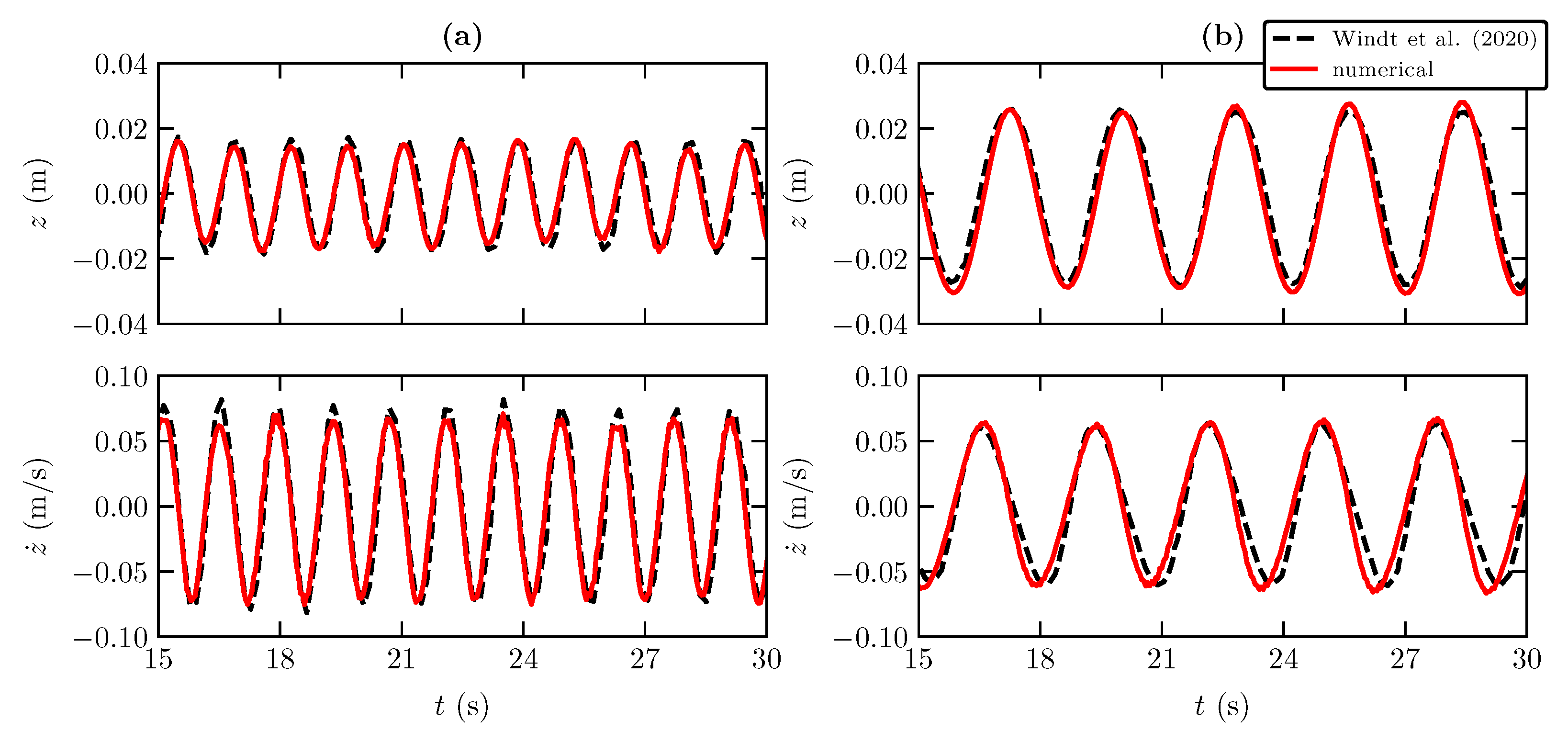
3. Numerical Model Validation

Since no detailed data are available for WEHC, the numerical model was first validated against experimental data of [43] for a Wavestar point-absorber-type device. This selected device has a working principle similar to WEHC, based on the interaction between the three different sub-systems: floater, lever arm and hydraulic PTO system. The floater is connected by a fixed arm to a hinge in the support platform where the rotational motion is damped by a hydraulic pump to absorb power in operational conditions. In [43], the experimental tests were carried out using a 1:5-scale Wavestar model. The schematic of the computational domain with the Wavestar model is shown in Figure 2. The channel is 24 m-long and has depth in the flat-bottom section of d = 3 m. A passive dissipative beach located at the end of the channel with a slope of 10 is used. The wave was generated in DualSPHysics using a piston-type wavemaker with active wave absorption system (AWAS) to absorb any reflected wave energy coming from the impact with the beach and Wavestar [44]. The Wavestar model was located 14 m from the wavemaker with an initial submergence of 0.4 m. The geometry and dimensions of the Wavestar model are given in Figure 2b.
In this study, four monochromatic wave conditions were considered. Table 1 presents the wave height H, wave period T and wave steepness k A , with k being the local wavenumber and A the wave amplitude of each test.
The hydraulic PTO system was modelled as an external force applied to the lever arm. This force was imposed 1 m from the revolute joint between lever arm and support platform at 52 , as shown in Figure 2b. As defined in [43], the applied PTO force is modelled as a linear spring–damper system:
F P T O ( t ) = D z ˙ ( t ) + K z ( t )
where the first term, D z ˙ ( t ) , is the linear damping force and second term, K z ( t ) , is the restitution force (linear spring) applied on the lever arm by the hydraulic pump, D and K being the damping and stiffness coefficients of the linear spring–damper PTO system, respectively. Similar to [43], K = 0 , and four different damping coefficients were used D = 0 , 50, 100 and 200 Nms.
Simulation accuracy is estimated by quantifying the discrepancy between the numerical and experimental Wavestar motion, including heaving position z and velocity z ˙ . Before performing these comparisons, a convergence analysis was carried out. The numerical resolution in DualSPHysics is defined using the initial interparticle distance d p . Four different d p were considered: d p = H / 5 , H / 10 , H / 15 and H / 20 . Similar to several applications of SPH models to simulate waves, a computational domain with d p = H / 10 shows a good agreement between numerical results and experimental data [26]. This discretisation allows a good balance between computational cost and simulation runtime. The d p chosen in this work is d p = 0.01 m, which corresponds to the resolution of d p = H / 10 for the smallest wave height tested (Test 1). With this resolution, about 624,500 particles are generated in DualSPHysics. The average time consumed was about 1 h to solve 50 s of physical time, running on an Nvidia RTX 3060.
The numerical and experimental time series of PTO position and velocity for Test 1 with different D are compared in Figure 3.
As can be observed, a good agreement was obtained between numerical results and the experimental data. However, a slight difference in both position and velocity can be found, especially for lower damping values (more amplitude of heaving motion). It is also observed that as the damping increases, the position and velocity decrease, as expected. The same behaviour was observed for other wave conditions and damping values; therefore, such results are not presented here. Figure 4 shows the time series of the PTO position and velocity for Test 2 with D = 0 and 200 Nms. All numerical results are consistent with the experimental data.
The time series for Test 3 and 4 with D = 200 Nms are compared in Figure 5. Similarly to Test 1 and 2, good agreement was found between the experimental data and the numerical results. Test 3 achieves slightly smaller differences with the experimental results than Test 4, even for the same wave height. This is due to a small lag in the wave period. However, the velocity appears to be slightly lagging behind when compared with the experimental velocity, with almost the same amplitude.
The time series of Wavestar motions obtained in the numerical model with different PTO values show a satisfactory agreement with the experimental data in the physical model tests. For a more quantitative comparison, the accordance between the numerical and experimental data was quantified using the average normalised root mean error (NRMSE) in amplitude. Table 2 shows NRMSE for the four tests with D = 0 . Overall, the NRMSE is less than 10%, although in some conditions it is slightly higher, caused by the small difference in phase between the numerical results and experimental data. For all wave conditions, the NRMSE decreases with increasing D.

4. Results and Discussion

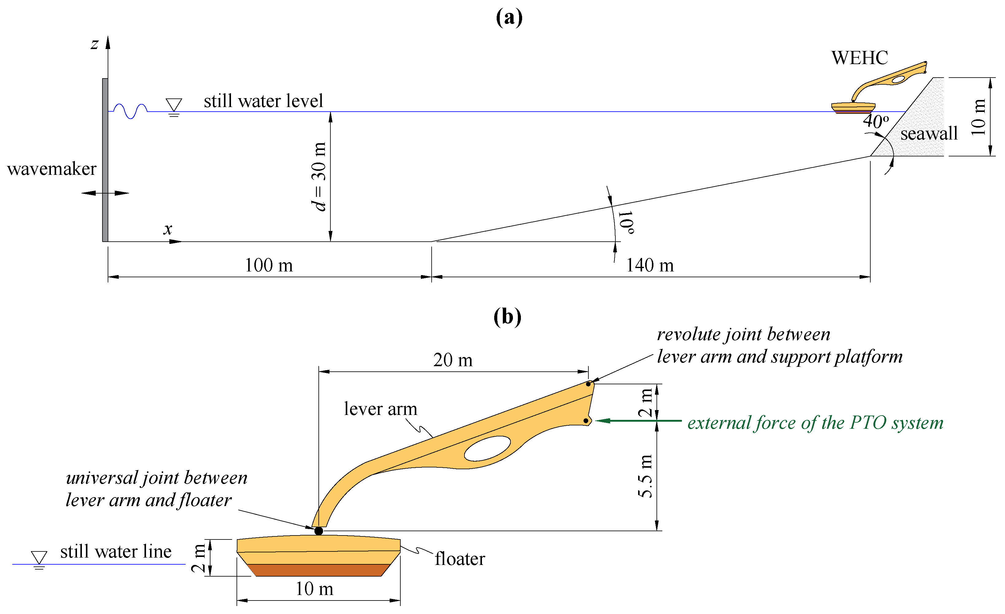
4.1. Simulation Set-Up

The power absorption of the WEHC device is investigated under full-scale sea wave conditions in the south-western coast of Portugal. The location of the western breakwater of the Port of Sines was considered for the present study. In order to correctly predict the power extracted from the waves, the first step is to correctly predict the incoming waves. For this reason, the waves chosen to simulate the device were based on the work of [45], who developed a detailed library of the most common waves and sea states along the Portuguese coast. Both regular and irregular sea states, and different operation modes and design parameters, were considered, including hydraulic PTO damping and breakwater geometries. Two different breakwater geometries were modelled: one as a straight wall with no porosity and another made by a double layer of cubic blocks with a porosity of around 40%, laying on an impermeable slope bed.
A schematic of the computational domain is shown in Figure 6. The channel is 240 m-long and has a depth in the flat-bottom region of d = 30 m. The WEHC device is located at the right-hand end of the channel with an initial submergence of 0.67 m. The geometry and dimensions of the device are presented in Figure 6b.
The computational domain was discretised with a d p = 0.1 m, i.e., d p = H / 10 for the smallest wave height tested. The simulations were also performed on an Nvidia RTX 3060. The average computational time was about 5 h for a resolution of 564,374 particles and 300 s of physical time.
The hydraulic PTO system is modelled as a single-piston effect with the external force given as
F P T O ( t ) = C P T O if z ( t ) < 0 0 if z ( t ) 0
where C P T O is the constant force applied 2 m below of the revolute joint between lever arm and support platform. The friction torque on the universal joint between lever arm and floater and the revolute joint between lever arm and support platform was modelled using the Coulomb friction coefficient of 0.16 [26].

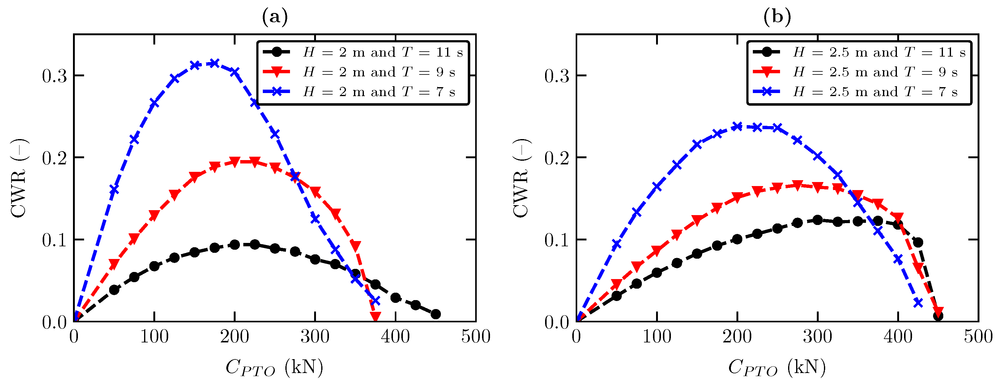
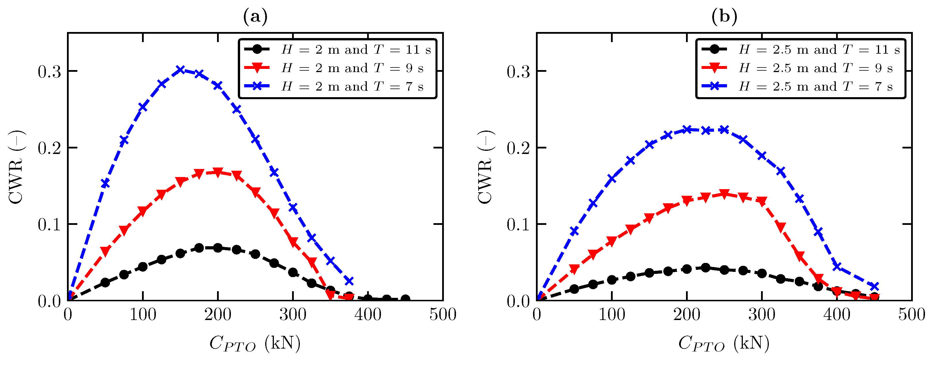
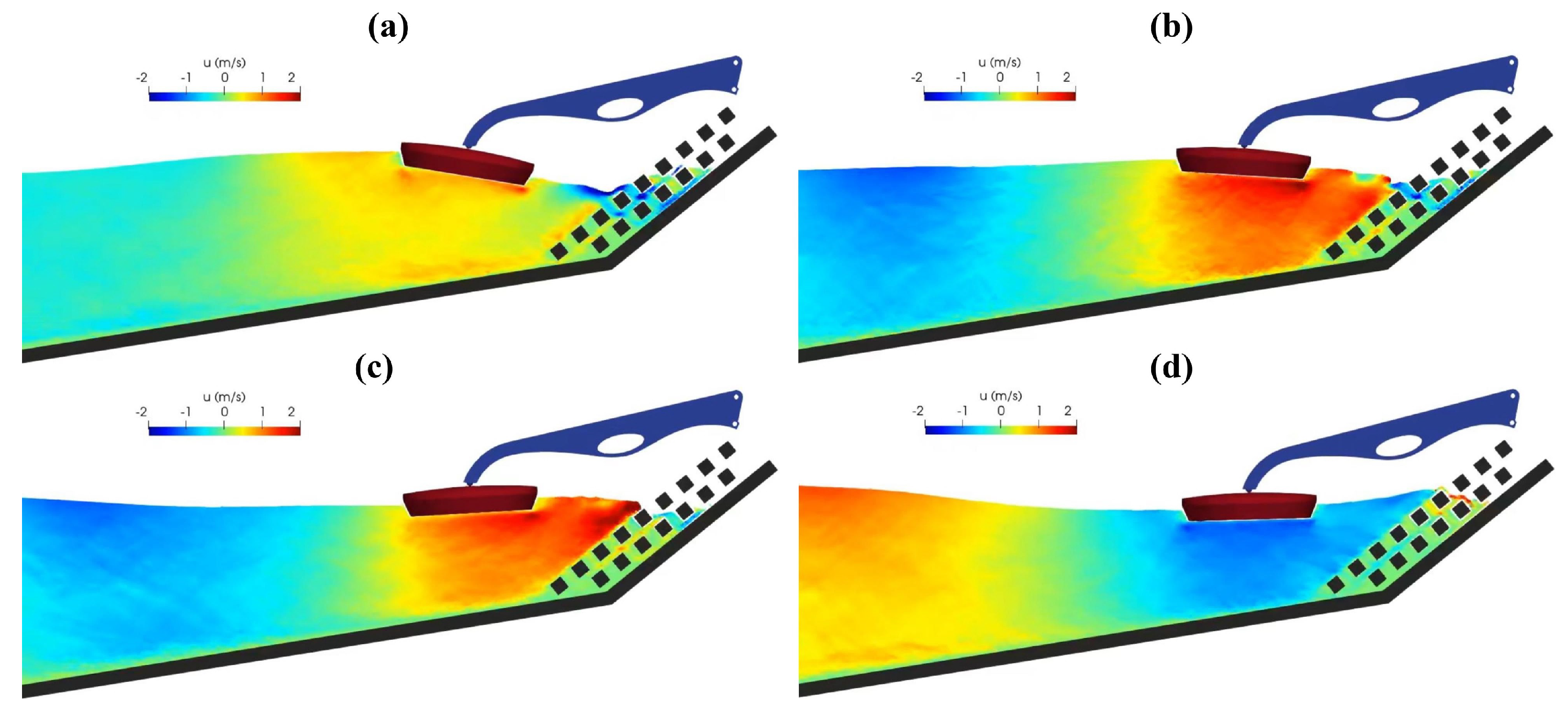
4.2. Power Absorption under Regular Sea State

The hydrodynamic response of a WEHC device under a regular sea state is analysed considering the capture width ratio (CWR), defined as the ratio between the average extracted power W o u t and the average incoming wave power W i n c , which is
CWR = W o u t W i n c
The W o u t is calculated as
W o u t = 1 t f t 0 t 0 t f F P T O ( t ) x ˙ ( t ) d t
where x ˙ is the velocity of the point where the external force is applied (Figure 6b), and t 0 and t f are the initial and final time, respectively.
According to linear wave theory, W i n c is calculated as
W i n c = 1 8 ρ g H 2 c g
where c g is the wave group velocity, and for this study, it is calculated as
c g = ω 2 k 1 + 2 k d sinh ( 2 k d )
where ω = 2 π f is the angular wave frequency, d is the water depth, f is the wave frequency and k is calculated by ω 2 = g k tanh ( k d ) .
Figure 7 compares the variation of CWR with C P T O for six different sea states presented in Table 3. These sea states’ characteristics are frequent on the south coast of Portugal [45].
A large variation of CWR with PTO damping can be observed in Figure 7. These constraints, imposed by the hydraulic PTO system, have a non-negligible influence on the power absorption of WEHC. As the C P T O increases, the CWR reaches its maximum. The curve shows almost similar trends for the different sea states tested, however, the maximum position is envisaged. For example, for H = 2 m and T = 7 s, the maximum CWR occurs with C P T O = 175 kN, and for H = 2 m and T = 9 s, it occurs with C P T O = 225 kN. A large variation of CWR is observed when the C P T O increases due to the rise of the latching effect of the hydraulic PTO system, where the floater remains stationary for as long as the mass forces are unable to overcome the resisting force introduced by the PTO system. In general, the CWR decreases when the wave period increases. For H = 2 m and T = 7 , the maximum CWR ≈ 32%, and for H = 2 m and T = 11 , the maximum CWR ≈ 19%. A similar trend is also observed when increasing the wave height, for example, for H = 2.5 m and T = 7 , the maximum CWR ≈ 23%. With increasing wave height, the maximum CWR occurs for a large C P T O . With increasing wave period, the CWR curve becomes flatter, and the maximum occurs at a higher value of C P T O for a longer period. This behaviour is caused by the non-linear waves interacting with the sea bottom that produces larger excitation forces, enlarging the bandwidth of the maximum CWR. A direct consequence of this behaviour is that it allows a simple control strategy for the pressure of the hydraulic PTO system based on wave period measurements and predictions from swell forecast models.
Figure 8 provides instantaneous snapshots of the velocity field in the vicinity of the WEHC device for H = 2 m and T = 7 s with straight breakwater. As expected, the flow field is characterised by a strong dynamical velocity field, with large acceleration near the floater. This causes differences in the turbulent field, characterised by the increase in the turbulent kinetic energy near the free surface and close to the floater.
As seen in Figure 8, the breakwater is a straight wall with no porosity, however, the breakwaters tend to be built of shaped rocks or cement blocks. This method of construction allows for more dissipation of wave energy on the breakwater, ensuring a better protection of the onshore structures. Given the proven capability of the DualSPHysics–Project Chrono coupling for simulating fluid–structure interaction [46], one additional breakwater geometry was tested in this study in order to obtain results on the influence of more realistic breakwaters. The variation of CWR with C P T O for six different sea states with H = 2 and 2.5 m, T = 7 , 9 and 11 s presented in Table 3 are shown in Figure 9. Similar trends of CWR are found for different breakwater geometries, however, the maximum position is slightly envisaged. For example, for H = 2 m and T = 7 s with straight breakwater, the maximum CWR occurs with C P T O = 175 kN, and for porous breakwater, it occurs with C P T O = 150 kN. In general, the CWR reduces by about 5% from straight breakwater. The reflected waves are reduced due to the porosity of the breakwater. However, its effect on the excitation forces is much smaller than the incident counterpart, so it has less effect on CWR. The breakwater porosity has more effects when H increases; indeed, complex interactions arise when H increases, mainly for higher T, and the excitation forces are much affected.
In order to illustrate the influence of the breakwater porosity and geometry on the flow field, the detailed instantaneous velocity field in the vicinity of the WEHC device for H = 2 m and T = 7 s with porous breakwater is given in Figure 10.
The geometry shows the dissipation of the energy from incoming waves. Moreover, energy dissipation also causes a reduction in wave reflection, which in turn reduces the WEHC position motion, leading to a lower CWR. Even though this effect has a negative impact on energy extraction, this is closer to how breakwaters are built.

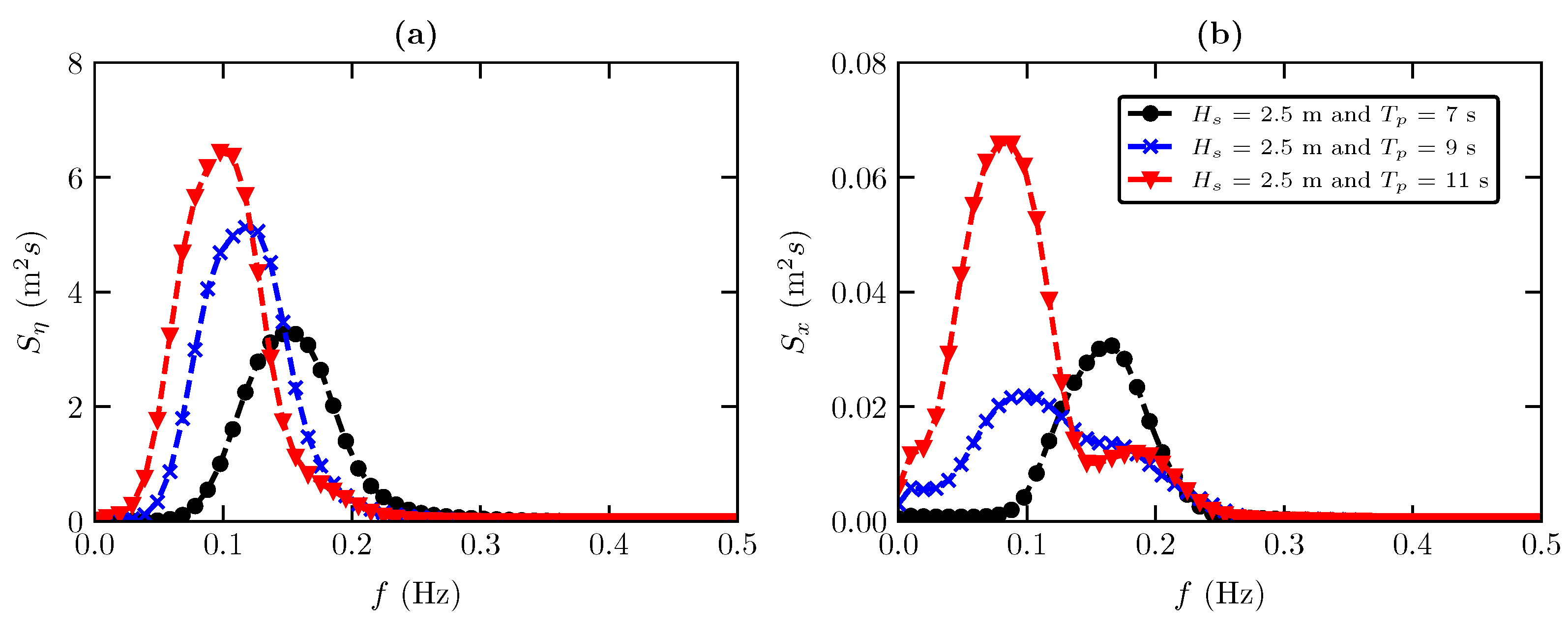
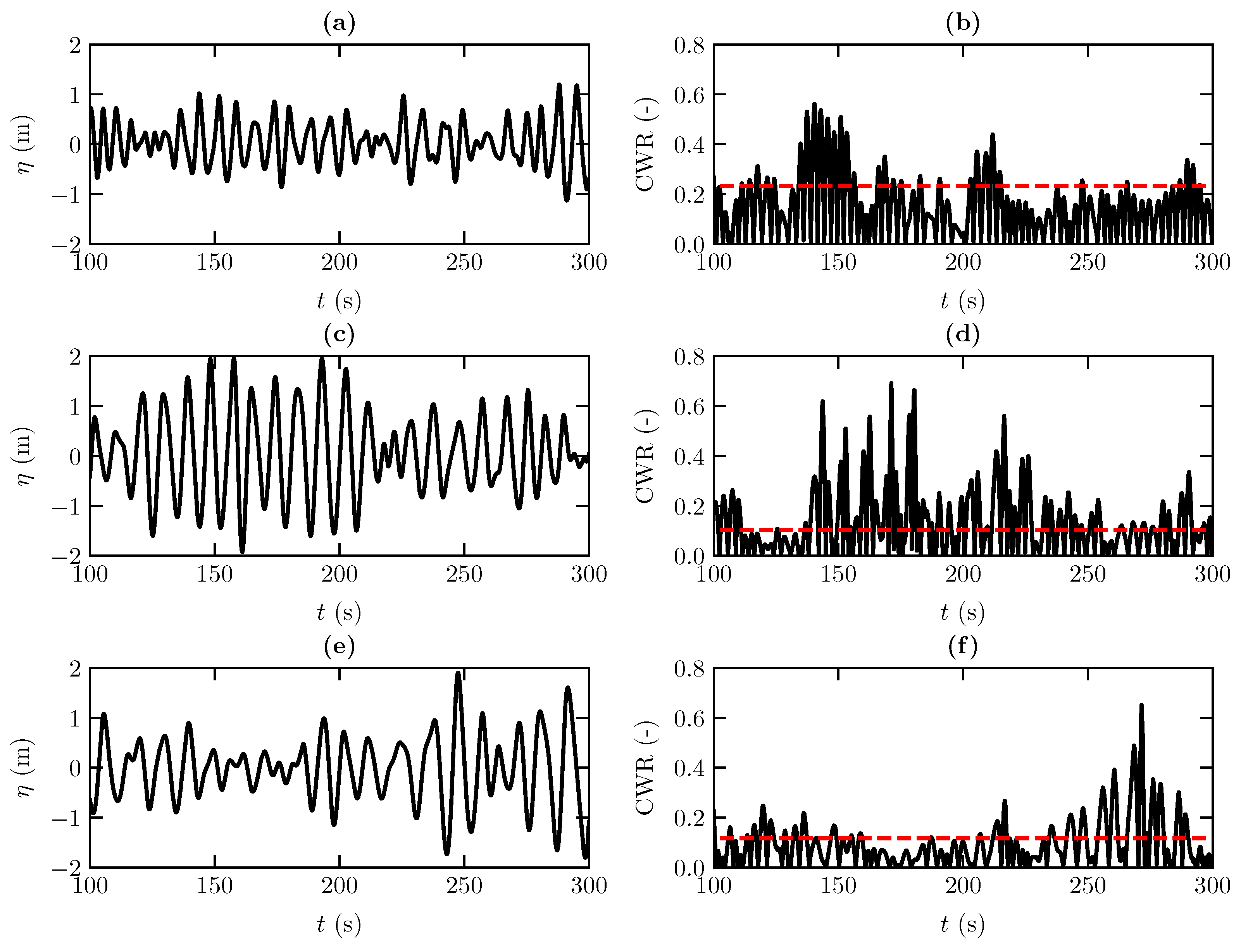
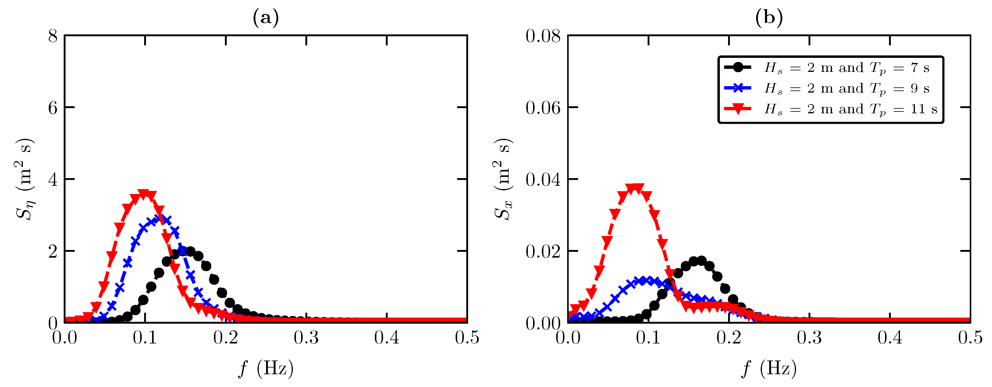
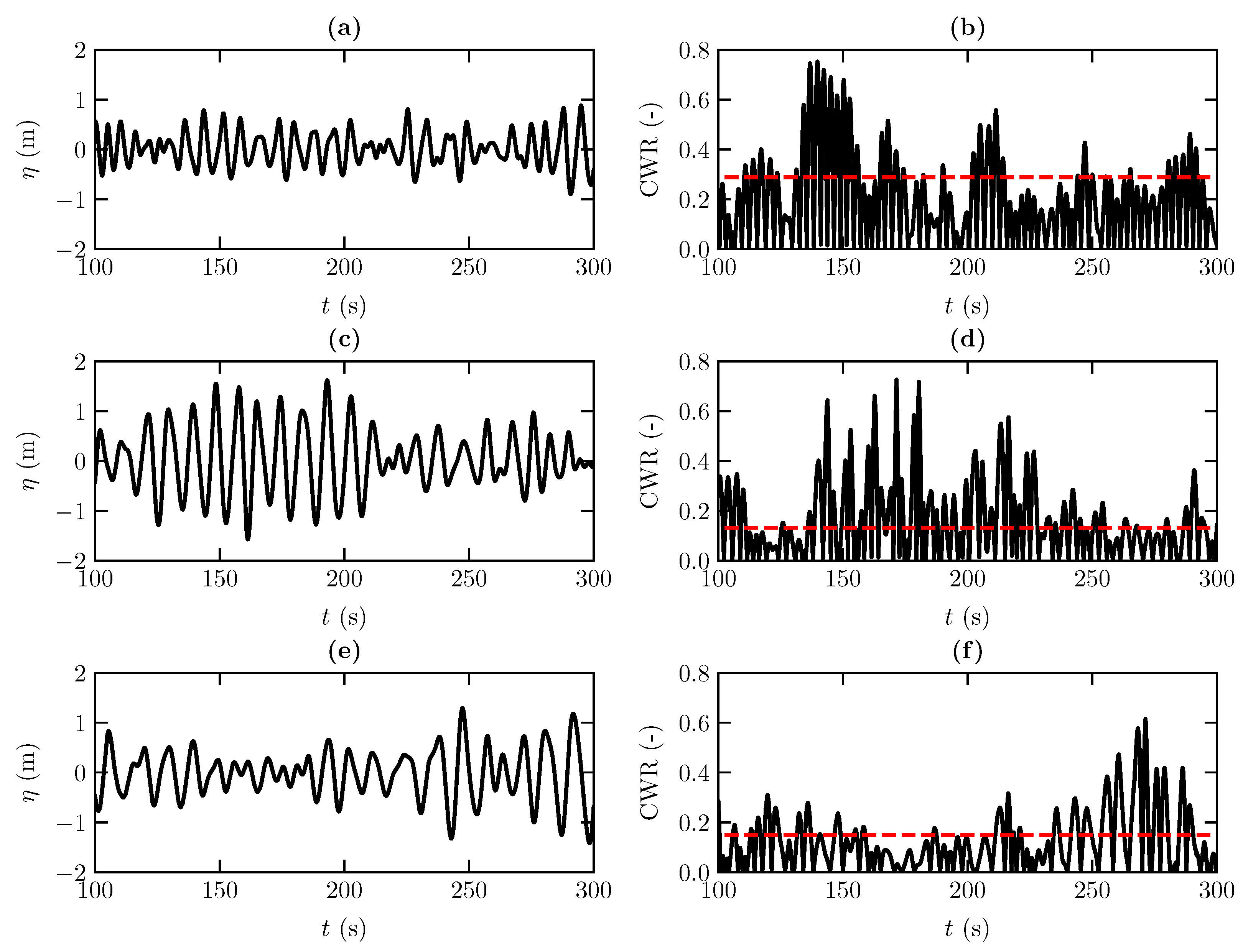
4.3. Power Absorption under Irregular Sea State

The ability of the model to reproduce more realistic wave conditions was tested by simulating the behaviour of the WEHC device for irregular wave conditions. The following JONSWAP (Joint North Sea Wave Observation Project) spectral shape was used [47]:
S η ( f ) = α g 2 ( 2 π ) 4 f 5 exp 5 4 f p f 4 γ exp ( f f p ) 2 2 σ 2 f p 2
where α = 0.291 , f p is the peak frequency, γ = 3.3 is peak enhancement factor, σ = 0.07 for f f p and σ = 0.09 for f > f p .
On the basis of the position time series, x ( t ) , and free surface elevation, η , the power density spectra of the WEHC motions S x and free-surface S η were calculated for each simulation. These power spectra were computed using Welch’s technique, in which each power spectral density is estimated by dividing the data into overlapping segments, computing a modified periodogram for each segment and averaging the periodograms. The Hann window with segment length of 1024 points and overlap of 50% was used.
As can be observed in Figure 11, the spectra also properly reflect the spectral peaks, i.e., where most of the energy is concentrated and, thus, the frequency range of the greatest interest. Three sea states were considered with the significant wave height H s = 2.5 m and peak period T p = 7, 9 and 11 s.
The time series of each sea state for 100 s < t < 300 s is shown in Figure 12. Similarly to the regular sea state, an increase in CWR with the peak period is observed. For H s = 2.5 m and T p = 7 s, a CWR of about 25% was found. The CWR for irregular waves is evaluated by Equation (11), where the average incident wave power was calculated as
W i n c = ρ g 0 c g ( f ) S η ( f ) d f
Figure 13 shows the power spectrum for three sea states considering significant wave height H s = 2 m and peak period T p = 7, 9 and 11 s. The spectra also properly reflect the spectral peaks.
Figure 14 shows the time series of each sea state for 100 s < t < 300 s. As for a regular sea state, an increase in CWR with the peak period is observed. For H s = 2 m and T p = 7 s, a CWR of about 30% was found.

5. Conclusions

This paper presents a numerical investigation of the power absorption of a constrained wave energy hyperbaric converter (WEHC) under full-scale sea wave conditions. A fully non-linear numerical model DualSPHysics was used to model the interaction between waves and each WEHC sub-system. The numerical model was first validated against the available experimental data of a similar device, a 1:5-scale Wavestar model. A good agreement was found between the experimental data and the numerical results, with an average normalised root mean error (NRMSE) of about 10%.
The numerical model was then employed to perform a study of the non-linear hydrodynamics of a constrained WEHC under regular and irregular sea states, and for different operation modes and design parameters, including hydraulic power take-off (PTO) damping and breakwater geometry. For regular waves, it was observed that the capture width ratio (CWR) is particularly sensitive to the variations in the PTO damping, although the absolute maximum CWR is less sensitive to the slightly lower variations applied to the PTO damping. It was also found that the influence of the wave height and wave period have an important effect on the CWR. For irregular waves, a similar trend on the CWR was observed, with CWR increasing with decreasing peak period and an increase in significant wave height. In general, the efficiency of the system is very dependent on the mechanical constraints (PTO system) and on the breakwater characteristics. These results show the potential and effectiveness of this type of numerical modelling approach for understanding the non-linear dynamics of WEHC in a full-scale application.

Author Contributions

Conceptualisation, M.B. and F.B.; methodology, M.B., M.G.N. and D.R.C.B.N.; software, J.M.D. and A.J.C.C.; validation, M.B., F.B., J.M.D. and A.J.C.C.; formal analysis, M.B. and F.B.; investigation, M.B., F.B., M.G.N., D.R.C.B.N., J.M.D. and A.J.C.C.; resources, M.B.; writing—original draft preparation, M.B., F.B., M.G.N., D.R.C.B.N., J.M.D. and A.J.C.C.; writing—review and editing, M.B., F.B., M.G.N., D.R.C.B.N., J.M.D. and A.J.C.C.; visualisation, M.B., J.M.D. and A.J.C.C.; project administration, M.B.; funding acquisition, M.B. All authors have read and agreed to the published version of the manuscript.

Funding

This research was funded by Fundação para a Ciência e a Tecnologia (FCT.IP) through the grant UIDB/00667/2020 (UNIDEMI). This work was also supported by the project SURVIWEC PID2020-113245RB-I00 and by the project ED431C 2021/44 “Programa de Consolidación e Estructuración de Unidades de Investigación Competitivas”. This study forms part of the Marine Science programme (ThinkInAzul) supported by Ministerio de Ciencia e Innovación and Xunta de Galicia with funding from the European Union NextGenerationEU (PRTR-C17.I1) and European Maritime and Fisheries Fund.

Acknowledgments

The authors acknowledge Fundação para a Ciência e a Tecnologia (FCT.IP) for its financial support through the grant UIDB/00667/2020 (UNIDEMI). This work was also supported by the project SURVIWEC PID2020-113245RB-I00 financed by MCIN/AEI/10.13039/501100011033 and by the project ED431C 2021/44 ”Programa de Consolidación e Estructuración de Unidades de Investigación Competitivas” financed by Xunta de Galicia, Consellería de Cultura, Educación e Universidade. This study forms part of the Marine Science programme (ThinkInAzul) supported by Ministerio de Ciencia e Innovación and Xunta de Galicia with funding from the European Union NextGenerationEU (PRTR-C17.I1) and European Maritime and Fisheries Fund.

Conflicts of Interest

The authors declare no conflict of interest.

References

  1. Estefen, S.F.; da Costa, P.R.; Ricarte, E.; Pinheiro, M.M. Wave Energy Hyperbaric Device for Electricity Production. In Proceedings of the Volume 5: Ocean Space Utilization, Polar and Arctic Sciences and Technology, The Robert Dean Symposium on Coastal and Ocean Engineering, Special Symposium on Offshore Renewable Energy, San Diego, CA, USA, 10–15 June 2007. [Google Scholar] [CrossRef]
  2. Estefen, S.F.; Esperanca, P.d.T.T.; Ricarte, E.; da Costa, P.R.; Pinheiro, M.M.; Clemente, C.H.P.; Franco, D.; Melo, E.; de Souza, J.A. Experimental and Numerical Studies of the Wave Energy Hyberbaric Device for Electricity Production. In Proceedings of the Volume 6: Nick Newman Symposium on Marine Hydrodynamics, Yoshida and Maeda Special Symposium on Ocean Space Utilization, Special Symposium on Offshore Renewable Energy, Estoril, Portugal, 15–20 June 2008. [Google Scholar] [CrossRef]
  3. Garcia-Rosa, P.B.; Cunha, J.P.V.S.; Lizarralde, F.; Estefen, S.F.; Costa, P.R. Efficiency optimization in a wave energy hyperbaric converter. In Proceedings of the 2009 International Conference on Clean Electrical Power, Capri, Italy, 9–11 June 2009. [Google Scholar] [CrossRef]
  4. Martínez, M.; Molina, M.; Machado, I.; Mercado, P.; Watanabe, E. Modelling and simulation of wave energy hyperbaric converter (WEHC) for applications in distributed generation. Int. J. Hydrogen Energy 2012, 37, 14945–14950. [Google Scholar] [CrossRef]
  5. Machado, I.R.; Watanabe, E.H.; Garcia-Rosa, P.B. Modeling and analysis of a sea wave energy converter. In Proceedings of the 2015 IEEE 13th Brazilian Power Electronics Conference and 1st Southern Power Electronics Conference (COBEP/SPEC), Fortaleza, Brazil, 29 November–2 December 2015. [Google Scholar] [CrossRef]
  6. Michele, S.; Sammarco, P.; d’Errico, M. Weakly nonlinear theory for oscillating wave surge converters in a channel. J. Fluid Mech. 2017, 834, 55–91. [Google Scholar] [CrossRef] [Green Version]
  7. Michele, S.; Renzi, E. A second-order theory for an array of curved wave energy converters in open sea. J. Fluids Struct. 2019, 88, 315–330. [Google Scholar] [CrossRef]
  8. Penalba, M.; Davidson, J.; Windt, C.; Ringwood, J.V. A high-fidelity wave-to-wire simulation platform for wave energy converters: Coupled numerical wave tank and power take-off models. Appl. Energy 2018, 226, 655–669. [Google Scholar] [CrossRef] [Green Version]
  9. Kleefsman, K.; Fekken, G.; Veldman, A.; Iwanowski, B.; Buchner, B. A Volume-of-Fluid based simulation method for wave impact problems. J. Comput. Phys. 2005, 206, 363–393. [Google Scholar] [CrossRef] [Green Version]
  10. Agamloh, E.B.; Wallace, A.K.; von Jouanne, A. Application of fluid–structure interaction simulation of an ocean wave energy extraction device. Renew. Energy 2008, 33, 748–757. [Google Scholar] [CrossRef]
  11. Hu, Z.Z.; Causon, D.M.; Mingham, C.G.; Qian, L. Numerical simulation of floating bodies in extreme free surface waves. Nat. Hazards Earth Syst. Sci. 2011, 11, 519–527. [Google Scholar] [CrossRef] [Green Version]
  12. Qian, L.; Causon, D.; Mingham, C.; Ingram, D. A free-surface capturing method for two fluid flows with moving bodies. Proc. R. Soc. Math. Phys. Eng. Sci. 2005, 462, 21–42. [Google Scholar] [CrossRef]
  13. Bangun, E.P.; Utsunomiya, T. Evaluation of Viscous Forces Acting on A Moving Body by Navier-Stokes Solver. In Proceedings of the OCEANS 2008—MTS/IEEE Kobe Techno-Ocean, Kobe, Japan, 8–11 April 2008. [Google Scholar] [CrossRef]
  14. Zhang, Y.; Zou, Q.; Greaves, D.; Reeve, D.; Hunt-Raby, A.; Graham, D.; James, P.; Lv, X. A Level Set Immersed Boundary Method for Water Entry and Exit. Commun. Comput. Phys. 2010, 8, 265–288. [Google Scholar] [CrossRef]
  15. Ransley, E.; Greaves, D.; Raby, A.; Simmonds, D.; Jakobsen, M.; Kramer, M. RANS-VOF modelling of the Wavestar point absorber. Renew. Energy 2017, 109, 49–65. [Google Scholar] [CrossRef] [Green Version]
  16. Shabana, A.A. Dynamics of Multibody Systems; Cambridge University Press: Cambridge, UK, 2005. [Google Scholar] [CrossRef]
  17. Mazhar, H.; Heyn, T.; Pazouki, A.; Melanz, D.; Seidl, A.; Bartholomew, A.; Tasora, A.; Negrut, D. CHRONO: A parallel multi-physics library for rigid-body, flexible-body, and fluid dynamics. Mech. Sci. 2013, 4, 49–64. [Google Scholar] [CrossRef] [Green Version]
  18. Tasora, A.; Serban, R.; Mazhar, H.; Pazouki, A.; Melanz, D.; Fleischmann, J.; Taylor, M.; Sugiyama, H.; Negrut, D. Chrono: An Open Source Multi-physics Dynamics Engine. In Lecture Notes in Computer Science; Springer International Publishing: Berlin/Heidelberg, Germany, 2016; pp. 19–49. [Google Scholar] [CrossRef]
  19. Ropero-Giralda, P.; Crespo, A.J.; Tagliafierro, B.; Altomare, C.; Domínguez, J.M.; Gómez-Gesteira, M.; Viccione, G. Efficiency and survivability analysis of a point-absorber wave energy converter using DualSPHysics. Renew. Energy 2020, 162, 1763–1776. [Google Scholar] [CrossRef]
  20. Ropero-Giralda, P.; Crespo, A.J.C.; Coe, R.G.; Tagliafierro, B.; Domínguez, J.M.; Bacelli, G.; Gómez-Gesteira, M. Modelling a Heaving Point-Absorber with a Closed-Loop Control System Using the DualSPHysics Code. Energies 2021, 14, 760. [Google Scholar] [CrossRef]
  21. Tagliafierro, B.; Martínez-Estévez, I.; Domínguez, J.M.; Crespo, A.J.; Göteman, M.; Engström, J.; Gómez-Gesteira, M. A numerical study of a taut-moored point-absorber wave energy converter with a linear power take-off system under extreme wave conditions. Appl. Energy 2022, 311, 118629. [Google Scholar] [CrossRef]
  22. Monaghan, J. Simulating Free Surface Flows with SPH. J. Comput. Phys. 1994, 110, 399–406. [Google Scholar] [CrossRef]
  23. Colagrossi, A.; Landrini, M. Numerical simulation of interfacial flows by smoothed particle hydrodynamics. J. Comput. Phys. 2003, 191, 448–475. [Google Scholar] [CrossRef]
  24. Brito, M.; García-Feal, O.; Domínguez, J.M.; Crespo, A.J.C.; Canelas, R.B.; Ferreira, R.M.L.; Neves, M.G. Coupling between DualSPHysics and Chrono-Engine: Towards large scale HPC multiphysics simulations. In Proceedings of the 11th SPHERIC International Workshop, Munich, Germany, 14–16 June 2016. [Google Scholar]
  25. Canelas, R.; Brito, M.; Feal, O.; Domínguez, J.; Crespo, A. Extending DualSPHysics with a Differential Variational Inequality: Modeling fluid-mechanism interaction. Appl. Ocean. Res. 2018, 76, 88–97. [Google Scholar] [CrossRef]
  26. Brito, M.; Canelas, R.; García-Feal, O.; Domínguez, J.; Crespo, A.; Ferreira, R.; Neves, M.; Teixeira, L. A numerical tool for modelling oscillating wave surge converter with nonlinear mechanical constraints. Renew. Energy 2020, 146, 2024–2043. [Google Scholar] [CrossRef]
  27. Domínguez, J.M.; Fourtakas, G.; Altomare, C.; Canelas, R.B.; Tafuni, A.; García-Feal, O.; Martínez-Estévez, I.; Mokos, A.; Vacondio, R.; Crespo, A.J.C.; et al. DualSPHysics: From fluid dynamics to multiphysics problems. Comput. Part. Mech. 2022, 9, 867–895. [Google Scholar] [CrossRef]
  28. Tasora, A.; Anitescu, M. A matrix-free cone complementarity approach for solving large-scale, nonsmooth, rigid body dynamics. Comput. Methods Appl. Mech. Eng. 2011, 200, 439–453. [Google Scholar] [CrossRef] [Green Version]
  29. Zheng, X.; Chen, G.; Cao, W.; Xu, H.; Zhao, R.; Xu, Q.; Kramer, M.; Touzé, D.L.; Borthwick, A.G.; Li, Y. On the energy conversion characteristics of a top-mounted pitching absorber by using smoothed particle hydrodynamics. Energy Convers. Manag. 2021, 250, 114893. [Google Scholar] [CrossRef]
  30. Crespo, A.; Domínguez, J.; Rogers, B.; Gómez-Gesteira, M.; Longshaw, S.; Canelas, R.; Vacondio, R.; Barreiro, A.; García-Feal, O. DualSPHysics: Open-source parallel CFD solver based on Smoothed Particle Hydrodynamics (SPH). Comput. Phys. Commun. 2015, 187, 204–216. [Google Scholar] [CrossRef]
  31. Monaghan, J.J. Smoothed Particle Hydrodynamics. Annu. Rev. Astron. Astrophys. 1992, 30, 543–574. [Google Scholar] [CrossRef]
  32. Fourtakas, G.; Dominguez, J.M.; Vacondio, R.; Rogers, B.D. Local uniform stencil (LUST) boundary condition for arbitrary 3-D boundaries in parallel smoothed particle hydrodynamics (SPH) models. Comput. Fluids 2019, 190, 346–361. [Google Scholar] [CrossRef]
  33. Wendland, H. Piecewise polynomial, positive definite and compactly supported radial functions of minimal degree. Adv. Comput. Math. 1995, 4, 389–396. [Google Scholar] [CrossRef]
  34. Mazhar, H.; Heyn, T.; Negrut, D.; Tasora, A. Using Nesterov’s Method to Accelerate Multibody Dynamics with Friction and Contact. ACM Trans. Graph. 2015, 34, 32:1–32:14. [Google Scholar] [CrossRef]
  35. Stewart, D.E. Rigid-Body Dynamics with Friction and Impact. SIAM Rev. 2000, 42, 3–39. [Google Scholar] [CrossRef] [Green Version]
  36. Anitescu, M.; Hart, G.D. A constraint-stabilized time-stepping approach for rigid multibody dynamics with joints, contact and friction. Int. J. Numer. Methods Eng. 2004, 60, 2335–2371. [Google Scholar] [CrossRef]
  37. Anitescu, M. Optimization-based simulation of nonsmooth rigid multibody dynamics. Math. Program. 2006, 105, 113–143. [Google Scholar] [CrossRef] [Green Version]
  38. Canelas, R.B.; Domínguez, J.M.; Crespo, A.J.; Gómez-Gesteira, M.; Ferreira, R.M. A Smooth Particle Hydrodynamics discretization for the modelling of free surface flows and rigid body dynamics. Int. J. Numer. Methods Fluids 2015, 78, 581–593. [Google Scholar] [CrossRef]
  39. English, A.; Domínguez, J.M.; Vacondio, R.; Crespo, A.J.C.; Stansby, P.K.; Lind, S.J.; Chiapponi, L.; Gómez-Gesteira, M. Modified dynamic boundary conditions (mDBC) for general-purpose smoothed particle hydrodynamics (SPH): Application to tank sloshing, dam break and fish pass problems. Comput. Part. Mech. 2022, 9, 911–925. [Google Scholar] [CrossRef]
  40. Crespo, A.J.C.; Gómez-Gesteira, M.; Dalrymple, R.A. Boundary Conditions Generated by Dynamic Particles in SPH Methods. Comput. Mater. Contin. 2007, 5, 173–184. [Google Scholar]
  41. Leimkuhler, B.J.; Reich, S.; Skeel, R.D. Integration Methods for Molecular Dynamics. In Mathematical Approaches to Biomolecular Structure and Dynamics; Mesirov, J.P., Schulten, K., Sumners, D.W., Eds.; Springer: New York, NY, USA, 1996; pp. 161–185. [Google Scholar] [CrossRef]
  42. Monaghan, J.J.; Kos, A. Solitary Waves on a Cretan Beach. J. Waterw. Port Coastal Ocean. Eng. 1999, 125, 145–155. [Google Scholar] [CrossRef]
  43. Windt, C.; Davidson, J.; Ransley, E.J.; Greaves, D.; Jakobsen, M.; Kramer, M.; Ringwood, J.V. Validation of a CFD-based numerical wave tank model for the power production assessment of the wavestar ocean wave energy converter. Renew. Energy 2020, 146, 2499–2516. [Google Scholar] [CrossRef]
  44. Altomare, C.; Domínguez, J.; Crespo, A.; González-Cao, J.; Suzuki, T.; Gómez-Gesteira, M.; Troch, P. Long-crested wave generation and absorption for SPH-based DualSPHysics model. Coast. Eng. 2017, 127, 37–54. [Google Scholar] [CrossRef]
  45. Pontes, M.T.; Aguiar, R.; Pires, H.O. A Nearshore Wave Energy Atlas for Portugal. J. Offshore Mech. Arct. Eng. 2003, 127, 249–255. [Google Scholar] [CrossRef]
  46. Zhang, F.; Crespo, A.; Altomare, C.; Domínguez, J.; Marzeddu, A.; ping Shang, S.; Gómez-Gesteira, M. DualSPHysics: A numerical tool to simulate real breakwaters. J. Hydrodyn. 2018, 30, 95–105. [Google Scholar] [CrossRef]
  47. Hasselmann, K.F.; Barnett, T.P.; Bouws, E.; Carlson, H.C.; Cartwright, D.E.; Enke, K.; Ewing, J.A.; Gienapp, H.; Hasselmann, D.E.; Kruseman, P.; et al. Measurements of wind-wave growth and swell decay during the Joint North Sea Wave Project (JONSWAP). Deut. Hydrogr. Z. 1973, 8, 1–95. [Google Scholar]
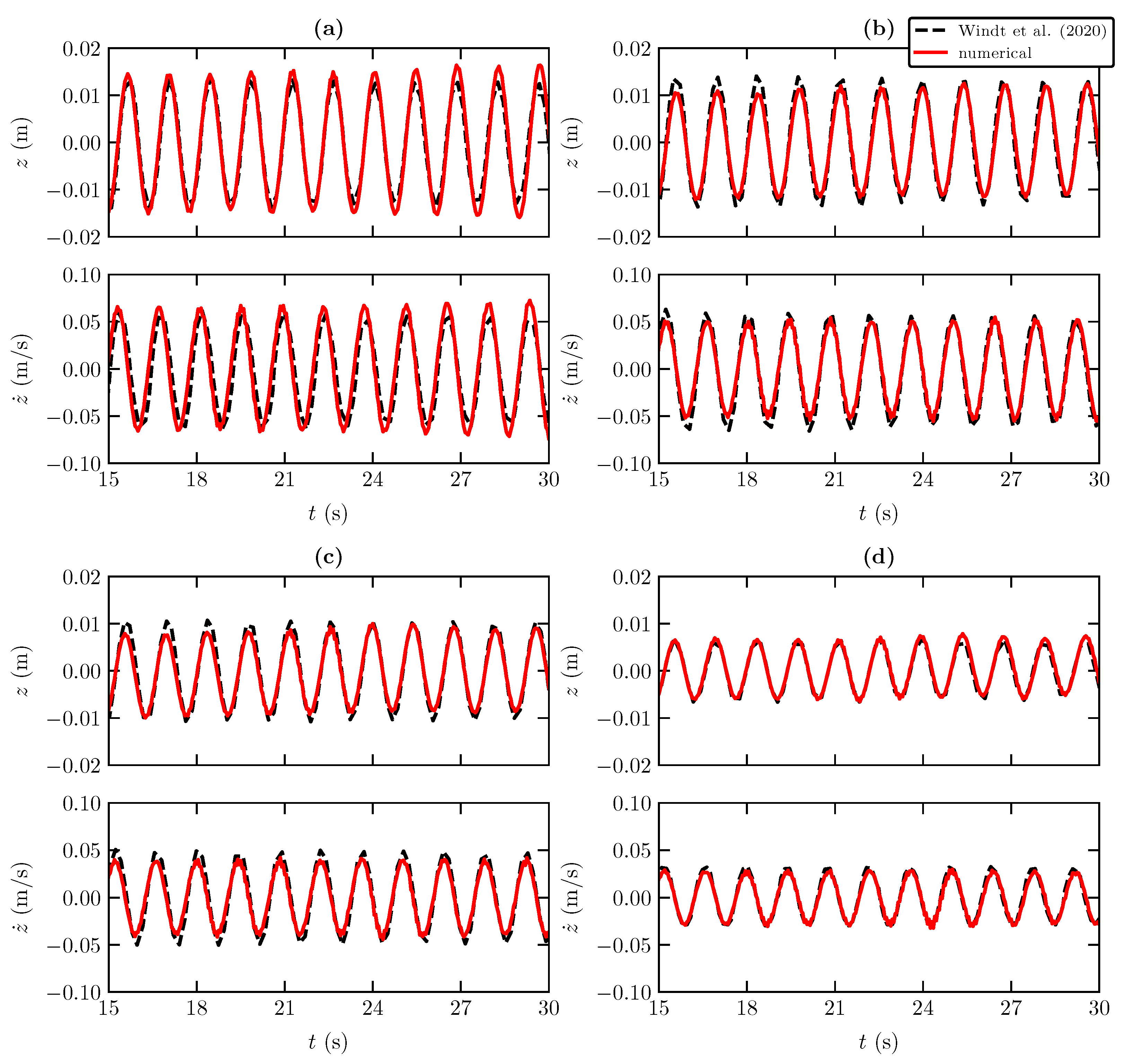
Figure 1. Schematic view of WEHC with main components (floater, lever arm, support platform and hydraulic PTO system), including the mechanical constraints among the three different sub-systems (universal joint between lever arm and floater, revolute joints between lever arm and support platform and hydraulic pump).
Jmse 10 01489 g001
Figure 2. Schematic (side) view of the numerical set-up: (a) channel with the Wavestar model (not to scale); (b) dimensions (in m) of the Wavestar model.
Jmse 10 01489 g002
Figure 3. Time series of position (top) and velocity (bottom) of the PTO system for Test 1 with (a) D = 0 , (b) D = 50 Nms, (c) D = 100 Nms and (d) D = 200 Nms [43].
Jmse 10 01489 g003
Figure 4. Time series of position (top) and velocity (bottom) of the PTO system for Test 2 with (a) D = 0 and (b) D = 200 Nms [43].
Jmse 10 01489 g004
Figure 5. Time series of position (top) and velocity (bottom) of the PTO system with D = 200 Nms for (a) Test 3 and (b) Test 4 [43].
Jmse 10 01489 g005
Figure 6. Schematic (side view) of the numerical set-up: (a) channel with the full-scale WEHC (not to scale); (b) dimensions (in m) of the WEHC model.
Jmse 10 01489 g006
Figure 7. Influence of PTO damping on the CWR for T = 7 , 9 and 11 s and (a) H = 2 m and (b) H = 2.5 m.
Jmse 10 01489 g007
Figure 8. Snapshots of the velocity field in the vicinity of the WEHC device for H = 2 m and T = 7 s with impermeable and straight breakwater at (a) t = 100 s, (b) t = 102 s, (c) t = 104 s and (d) t = 107 s.
Jmse 10 01489 g008
Figure 9. Influence of breakwater porosity and geometry and PTO damping on the CWR for T = 7 , 9 and 11 s and (a) H = 2 m and (b) H = 2.5 m.
Jmse 10 01489 g009
Figure 10. Snapshots of different instants of the velocity field in the vicinity of the WEHC device for H = 2 m and T = 7 s with porous breakwater at (a) t = 100 s, (b) t = 102 s, (c) t = 104 s and (d) t = 107 s.
Jmse 10 01489 g010
Figure 11. Power spectrum of (a) free-surface elevation measured at x = 220 m and of (b) horizontal position of hydraulic PTO system for H s = 2.5 m and T p = 7, 9 and 11 s.
Jmse 10 01489 g011
Figure 12. Detail of surface elevation and CWR for (a,b) H s = 2.5 m and T p = 7 s, (c,d) H s = 2.5 m and T p = 9 s, (e,f) H s = 2.5 m and T p = 11 s. In the power capture curve, the horizontal dashed red line indicates the mean power capture.
Jmse 10 01489 g012
Figure 13. Power spectra of (a) free-surface elevation measured at x = 220 m and of (b) the horizontal position of the hydraulic PTO system for H s = 2 m and T p = 7, 9 and 11 s.
Jmse 10 01489 g013
Figure 14. Detail of surface elevation and CWR for (a,b) H s = 2 m and T = 7 s, (c,d) H s = 2 m and T = 9 s, (e,f) H s = 2 m and T = 11 s. In the power capture curve, the horizontal dashed red line indicates the mean power capture.
Jmse 10 01489 g014
Table 1. Wave conditions considered for the validation of Wavestar.
Test 1Test 2Test 3Test 4
H (m)0.10.150.250.25
T (s)1.41.41.42.8
k A (-)0.1030.1540.2570.07
Table 2. Average NRMSE for the different wave states with D = 0 .
Test 1Test 2Test 3Test 4
z (m)10%8%7%9%
z ˙ (m/s)11%6%5%13%
Table 3. Regular wave conditions considered in the numerical tests.
State 1State 2State 3State 4State 5State 6
H (m)2222.52.52.5
T (s)79117911
k A (-)0.0830.0540.0400.1040.0670.050
Publisher’s Note: MDPI stays neutral with regard to jurisdictional claims in published maps and institutional affiliations.

