Article

Bearing Characteristics of Multi-Wing Pile Foundations under Lateral Loads in Dapeng Bay Silty Clay

1
School of Civil Engineering, Architecture of Henan University, Kaifeng 475004, China
2
Water Resources Survey and Monitoring Center, Henan Provincial Institute of Natural Resource Monitoring and Land Remediation, Zhengzhou 450046, China
3
Engineering Technology Research Center for Embankment Safety and Disease Control, Ministry of Water Resources, Zhengzhou 450003, China
4
The College of Geography and Environment Science, Henan University, Kaifeng 475004, China
*
Author to whom correspondence should be addressed.
J. Mar. Sci. Eng. 2022, 10(10), 1391; https://doi.org/10.3390/jmse10101391
Submission received: 1 September 2022 / Revised: 24 September 2022 / Accepted: 26 September 2022 / Published: 29 September 2022
(This article belongs to the Special Issue Coastal Engineering: Sustainability and New Technologies)

Abstract

:
This study provides a theoretical basis for reinforcement of the soil around multi-wing piles. Limit analysis was used to determine the ultimate lateral capacity (ULC) of three- and four-wing piles in Dapeng Bay silty clay. The effects of the pile–soil interaction coefficient α, wing width Bw, and lateral-load direction β on the ULC of the pile and the shear plastic zone range of the surrounding soil were analyzed. The normalized ULC of the three-wing pile decreased when the wing–diameter ratio increased. When Bw was 0.15 m and α was 0.4, the ULC of the four-wing pile was 19% higher than that of the three-wing pile. As β increased, the normalized ULC of the four-wing pile decreased, whereas that of the three-wing pile went through a minimum at 30°. The size of the soil shear plastic ring did not depend on α for either pile type; it increased around the three-wing (but not the four-wing) pile with changes in β. However, there was also a double plastic ring of broken soil around the four-wing pile. The four-wing pile had a more symmetrical influence on the soil around the pile than the three-wing pile.

1. Introduction

Because piles can bear vertical and lateral loads, they are widely used in the foundation of street-lamp posts, coastal trestle bridges, and offshore wind-power poles [1,2,3,4,5]. The action of typhoon and tide on a bay trestle will cause the trestle to cut and move sideways. Wings can be added along the pile to improve its ultimate lateral capacity (ULC) [6]. Different forms of wing piles have been developed [7,8]. Multi-wing piles with three or four wings at the same angle are especially common. There will be some saturated clay around such winged piles in a bay trestle. Therefore, it is important to determine the ULC of the wing piles and the extent of the plastic zone of the surrounding soil under lateral loading.
Many calculation methods for studying the factors that influence wing–pile ULC have been proposed. Dührkop and Grabe [9] modified the key parameters of the p–y-curve procedure to calculate the bearing capacity of the wing pile. Zhou et al. [10,11] used complex-variable elasticity and the finite-element method to calculate the ULC of noncircular piles. Nasr [6] determined that wing–pile ULC is affected by the geometry and position of the wing plate. Moreover, when the wing–plate length is less than 0.4 times the pile length, the lateral bearing capacity of the pile increases with wing–plate length; however, when it is greater than half the pile length [7], the influence of the wing–plate length on ULC becomes insignificant. Yaghobi et al. [12] calculated that the ULC of a wing pile with a diameter of 40 mm was 29% higher than that of a regular pile with the same diameter. Moreover, three-dimensional finite element analysis shows that the length of the wing plate has more effect on ULC than does the width. Increasing the length of the wing plate improves the bearing capacity and reduces the displacement of the pile head [13,14].
The response of pile foundations under lateral loads are usually analyzed using the beam-on-nonlinear-Winkler-foundation (BNWF) model in granular soil [15,16]. Limit–analysis theory, which considers the plastic deformation of soil, is widely used to study the ultimate bearing capacity of irregular-section piles and the relationship between the pile and soil interactions. Randolph and Houlsby [17] accurately calculated the ULC of circular piles from the plasticity theory. Martin [18,19] proposed that the actual ULC of circular piles is between the upper- and lower-limit solutions by limit-analysis theory. Keawsawasvong and Ukritchon [4] found that the upper- and lower-limit solutions from limit analysis, obtained with the OPTUM G2 software program, allow the ULC of I-shaped piles in undrained clay to be calculated perfectly; load direction also affected ULC. Zhou et al. [11] determined that, as the wing plate becomes thinner, it exerts a more significant effect on the normalized ULC of an XCC pile; load direction again has some effect. Truong and Lehane [20] noted that, when a pile fails, the displacement vector of the soil around it changes accordingly. The displacement–vector range of the soil around a concave pile is larger than that around a rectangular pile with the same section area, and the vector displacement of the soil around a circular pile is smaller than that around triangular, concave, and rectangular piles.
Limit-analysis theory can also be used to study the ULC of pile groups. Zhou et al. [21] proposed a design method for XCC pile groups in undrained clay. For a triangular composite foundation [22], a wide pile spacing can realize the best combination of pile groups, thus improving ULC. Modifying the single-pile py curve was also used in the analysis of the lateral loading behavior of pile groups [23,24].
The aforementioned studies investigated the ULCs of piles with different cross-sections (round, square, and h-shaped) in undrained clay and the failure mechanism of the soil around the piles. However, the ULCs of three-wing and four-wing piles in bay trestles have not been studied. In particular, the soil plastic-zone range around a wing pile, which partly determines the soil reinforcement range, has not been investigated. Hence, this study uses the upper and lower solutions from limit analysis to study the ULC of rigid multi-wing piles in Dapeng Bay and to determine the range of the silty-clay plastic zone. Furthermore, the effects of the three main factors (the pile–soil interaction coefficient, wing–diameter ratio, and lateral-load direction) on the ULC of a multi-wing pile are analyzed, and the effects of parameter changes on the shear plastic-zone range of the soil are explored. This provides a basis for the reinforcement of the soil around multi-wing piles in bay areas.

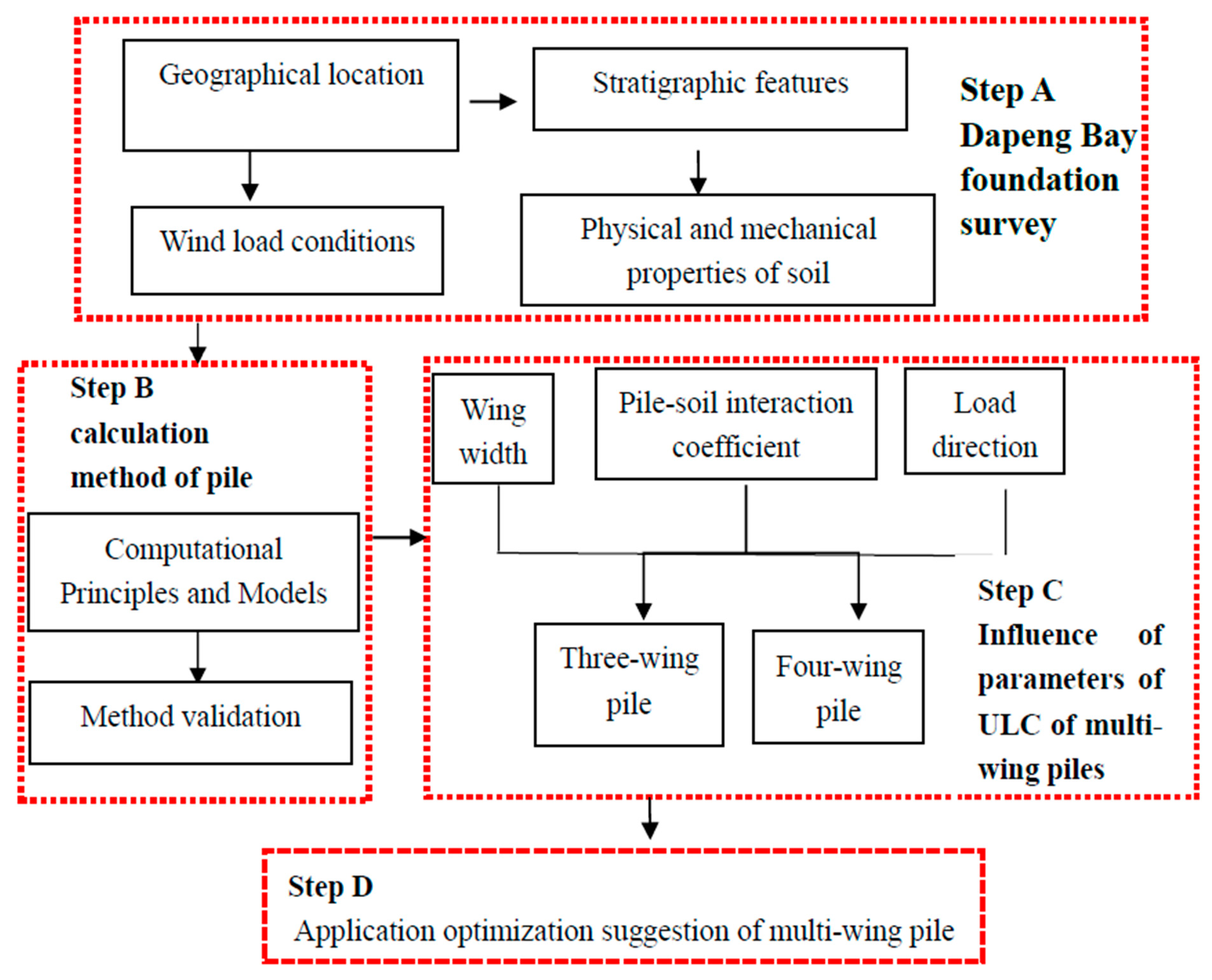
2. Research Area and Methodology

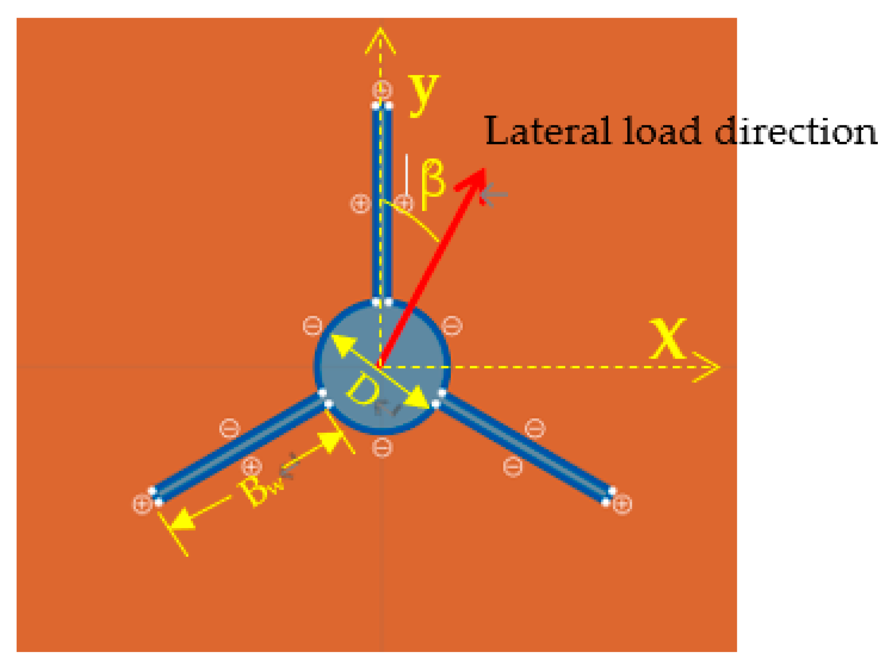
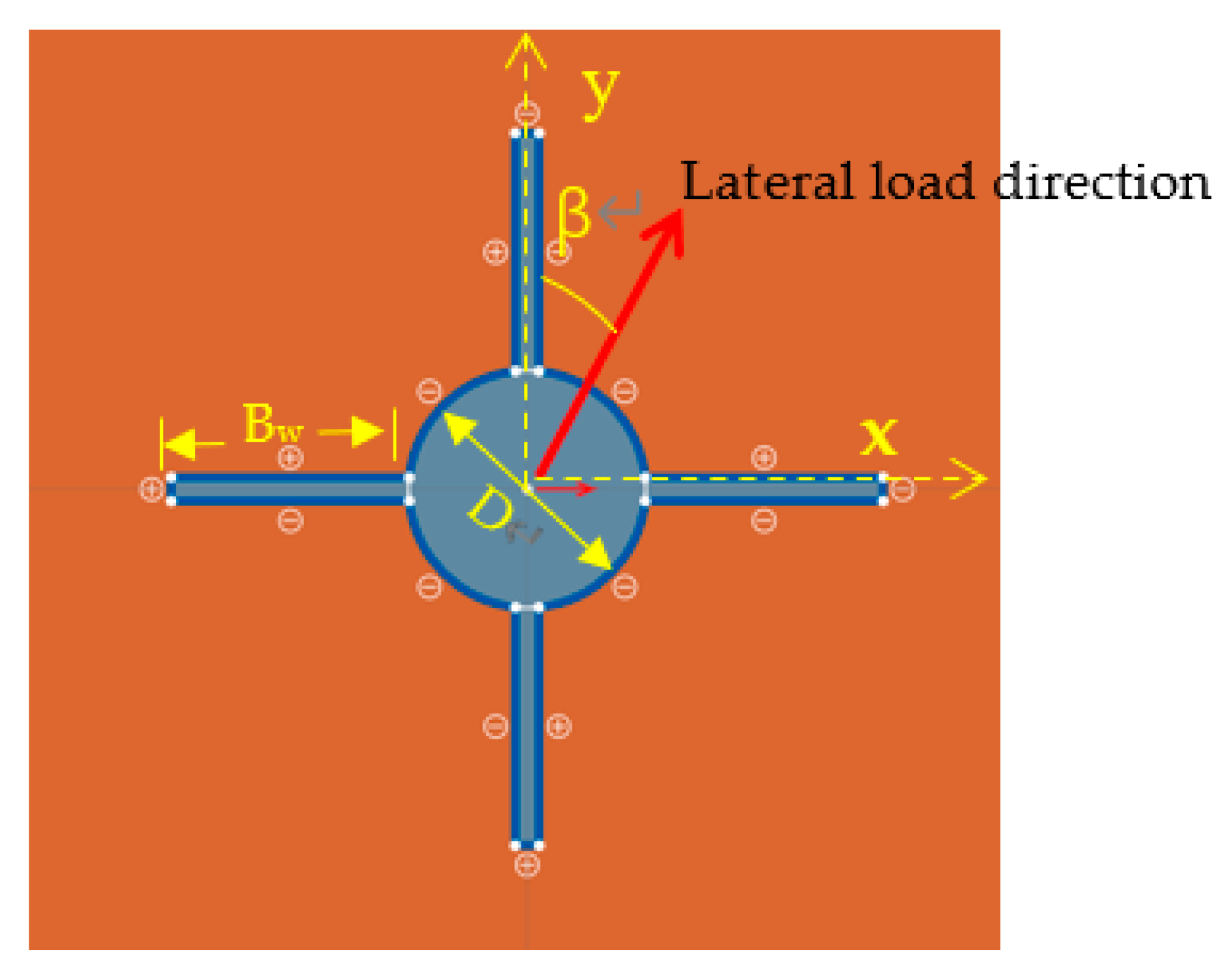
2.1. Description of the Calculated Section of the Multi-Wing Pile

A sightseeing trestle is planned to be built in the coastal bay area of Dapeng, Yantian District, Shenzhen, near E114°23′30″, N22°26′30″. The bay is trough-shaped with exposed Quaternary deposits (Qme) and Quaternary alluvial–pluvial sediments (Qal+pl), with binary or multiple structures. The upper part is silty clay with an average thickness of 2.5 m, and the lower part is an interlayer of sandy soil and clay soil with an average thickness of 5 m. The maximum wind speed of typhoons in this area is greater than 40 m/s, the maximum wind speed under non-typhoon conditions is 10–29 m/s, and the main wind direction is northeast. In order to resist the horizontal loads caused by typhoons and tides, the foundation of the sightseeing trestle uses multi-wing piles. The research process for the design and selection of multi-wing piles is shown in Figure 1. The physical and mechanical characteristics of the soil around the winged pile are shown in Table 1.

2.2. Calculated Section of a Multi-Wing Pile

Two types of multi-wing pile have been selected for the Dapeng Bay trestle foundation design: three-wing and four-wing. The calculated section of the three-wing pile includes three wings and one circular pile (Figure 2). The angle between the wings is 120°, the width of each wing is Bw, and the diameter of the circular pile is D. The lateral load acts on the section of the pile head, and the angle between the lateral load direction and the wing is β. When β = 0, the direction of the lateral load aligns with the wing orientation; when β = 60°, the lateral load acts along the angular bisector of two wings. Similarly, the calculated section of the four-wing pile includes four wings and one circular pile (Figure 3). In the four-wing pile, the lateral load acts along the angular bisector of two wings when β = 45°. Other parameters are the same as for the three-wing pile. The value of the interaction coefficient α; between the multi-wing pile and the soil varies from 0 to 1. The soil around the pile is silty clay with undrained shear strength Su.
In the calculation, the multi-wing pile will be considered completely rigid. Its normalized ULC (denoted NF) is given by [25]:
N F = F S u D e = f   ( D e B w ,     α ,     β )
where F is the ultimate lateral load of the pile, and De is the equivalent diameter of the multi-wing–pile cross-section, which is related to the maximum section width of the pile [9]. The equivalent diameter of the three-wing–pile cross-section is
D e = D + B w   ( 1 + cos   60 ° ) ;
and that of the four-wing pile cross-section is
D e = D + 2 B w
NF is affected by changes in three parameters (wing–diameter ratio De/Bw, the lateral-load direction β, and the pile–soil interaction coefficient a). F can be calculated by performing finite-element limit analysis (FELA) using OPTUM G2 software [4,11]. The FEM basis of OPTUM G2 is to use the upper bound theorem and the lower bound theorem of limit analysis to solve the ultimate load of the structure [11]; the lower-bound and upper-bound solutions provide a safe estimate of the real ULC. Thereafter, by substituting Equation (2) or Equation (3) into Equation (1), the empirical formula for the normalized ultimate bearing capacity of the multi-wing pile can be obtained through parameter fitting; this is very convenient for engineering.

2.3. Verifying the Calculation Results for the Pile–Soil Interaction

Randolph and Houlsby [17] used the lower-bound theorem of limit analysis to find the ULC of a 0.5-m-diameter circular pile in saturated soft clay (Figure 4). In this study, a numerical model was established to calculate the ultimate bearing capacity of the same circular pile by conducting FELA in OPTUM G2. The results were compared with those of Randolph and Houlsby to determine the relevant calculation parameters of the pile–soil model. When considering the influence of the calculation-model boundary on ULC [26,27], the established numerical soil model considers a plane circle with diameter 8 m and an internal circular pile diameter (D) of 0.5 m. The material of the plane circle was saturated clay, and its strength (Su) was 50 MPa. The pile was made of a rigid material; the plate material is set on the contact surface around the pile to study the change of the pile–soil interaction coefficient.
According to the difference and convergence rate of the calculation results of the calculation model after several trial calculations, the number of model elements was set to 10,000, and an adaptive grid was selected (shown in Figure 4a). The initial number of elements was 1000, and the number of adaptive iterations was three. The boundary of the soil model was fully constrained. When the interaction coefficient between the pile and soil changed from 0 to 1, two cases of NF were calculated according to the upper- and lower-bound solutions of the limit analysis; the difference between them was small (Figure 4b). Randolph and Houlsby ‘s solution fell between the upper- and lower-bound solutions and was in good agreement with the latter.

3. Numerical Methods of Analysis

3.1. Three-Wing Pile

3.1.1. Effect of Wing–Diameter Ratio on Normalized Ultimate Lateral Capacity

The width of the wing plate affects the bearing capacity during experimentation on the wing pile [8]. To study the interaction between the pile ULC and the wing width Bw under the lateral load, OPTUM G2 was used to calculate the ULC of the three-wing pile. The calculation model for the three-wing pile is shown in Figure 2. The established numerical model of the soil was a plane circle with diameter 8 m and internal circular-pile diameter 0.2 m. The thickness of the wing plate was 0.02 m. The direction of the lateral load (β) was 0°. The material of the plane circle was saturated clay, and its strength (Su) was 50 MPa. The pile body is made of steel pipe with a thickness of 10 mm, and the wing plate is a steel plate with a thickness of 8 mm. Compared with silty clay in Dapeng Bay, their strength is higher than soil, so the pile and three wings were assumed rigid. Wing widths of 0.05 m, 0.1 m, 0.15 m, 0.2 m, 0.25 m, and 0.3 m were considered. According to Equation (2), the equivalent diameters of the three-wing pile (De) were therefore 0.275 m, 0.35 m, 0.425 m, 0.5 m, 0.575 m, and 0.65 m. Similarly, the wing–diameter ratios (De/Bw) were 5.5, 3.5, 2.8, 2.5, 2.3, and 2.17.
The number of model elements was set to 10,000, and the adaptive grid was selected. The initial number of elements was 1000, and the number of adaptive iterations was three. The boundary of the soil model was fully constrained. The relationship between NF and De/Bw is shown in Figure 5—to observe the influence of the change of the pile–soil interaction coefficient on the bearing capacity of multi-wing pile and provide a basis for the design of multi-wing pile under the most dangerous situation. The pile–soil interaction coefficients changed from 0 to 1, according to the limit analysis.
Although the pile–soil interaction coefficients are different, the fitted-curve trends in Figure 5 are identical. When the soil loading interaction coefficient is greater than 0.4, the different fitting curves overlap. The influence of the wing–diameter ratio on the shear plastic zone of the soil is shown in Figure 6; the pile–soil interaction coefficient was set to 0.4, according to the upper-bound solution from limit analysis.

3.1.2. Effect of Pile–Soil Interaction Coefficient on Normalized Ultimate Lateral Capacity

The pile–soil interaction coefficient affects the pile-bearing capacity and the shear plastic ring of the soil [11]. To study this, the ULC of the three-wing pile was calculated by OPTUM G2. The calculation model for the three-wing pile is shown in Figure 2. The other model parameters were the same as those previously described. The relationship between the pile–soil interaction coefficient (α) and the normalized ultimate lateral capacity of the three-wing pile (NF) when α changed from 0 to 1, according to the solution of the limit analysis, is illustrated in Figure 7.
Although the pile–soil interaction coefficients are different, the fitted-curve trends in Figure 7 are identical. When the wing–diameter ratio was lower than 2.3, the soil had a double-circular plastic zone (see Figure 6). The influence of the pile–soil interaction coefficient on the shear plastic zone of the soil when De/Bw was set to 2.3, according to the upper bound solution of the limit analysis, is shown in Figure 8.

3.1.3. Effect of the Lateral-Load Direction on Normalized Ultimate Lateral Capacity

Different directions of the load affect the ultimate lateral bearing capacity of piles with different cross-sections [8]. The ULC of the three-wing pile was calculated by OPTUM G2 to elucidate the influence of the lateral load direction. The calculation model for the three-wing pile is shown in Figure 2. The wing width was set to 0.2 m. The lateral-load angle (β) ranged from 0° to 60°; it can be expressed in radians as β’ = βπ/180°. The wing–diameter ratio De/Bw was set to 2.5. The other model parameters were the same as those previously described. The relationship between β’ and NF as the pile–soil interaction coefficients changed from 0 to 1, according to limit analysis, is shown in Figure 9.
Although the pile–soil interaction coefficients are different, the fitted curve trends in Figure 9 are identical. When the soil loading interaction coefficient exceeded 0.4, the range of the plastic zone of the soil in Figure 8 stopped increasing. De/Bw was 2.5 when the pile–soil interaction coefficient was 0.4. The influence of the pile–soil interaction coefficient on the shear plastic zone of the soil, according to the upper bound solution of limit analysis, is shown in Figure 10.

3.2. Four-Wing Pile

3.2.1. Effect of Wing–Diameter Ratio on Normalized Ultimate Lateral Capacity

To study the interaction between the four-wing pile and the soil under the lateral load, the ULC of a four-wing pile was calculated using OPTUM G2. In addition, the influence of the wing width on ULC was studied. The calculation model for the four-wing pile is shown in Figure 3. The established numerical model of the soil was a plane circle with diameter 8 m and an internal circular pile with diameter 0.2 m. The thickness of the wing plate was 0.02 m. The lateral load angle (β) was 0°. The material of the plane circle was saturated clay with Su = 50 MPa. The pile and four wings were assumed rigid. The wing widths were set to 0.05 m, 0.1 m, 0.15 m, 0.2 m, 0.25 m, and 0.3 m. According to Equation (3), the equivalent diameters were 0.3 m, 0.4 m, 0.5 m, 0.6 m, 0.7 m, and 0.8 m, corresponding to wing–diameter ratios 6, 4, 3.3, 3, 2.8, and 2.7.
The calculation conditions were the same as in the three-wing case above. Figure 11 shows the relationship between De/Bw and NF for the four-wing pile when the pile–soil interaction coefficients changed from 0 to 1, according to the solutions of the limit analysis.
Although the pile–soil interaction coefficients were different, the fitted curve trends in Figure 11 were identical. When the soil loading interaction coefficient was greater than 0.4, the different fitting curves overlapped. The influence of various wing widths on the shear plastic zone of the soil around the four-wing pile for a pile–soil interaction coefficient of 0.4, according to the upper bound solution of the limit analysis, is shown in Figure 12.

3.2.2. Effect of Pile–Soil Interaction Coefficient on Normalized Ultimate Lateral Capacity

The influence of the pile–soil interaction coefficient on the ULC of the four-wing pile, (calculated by OPTUM G2) was studied. The calculation model for the four-wing pile is shown in Figure 3. The other model parameters were the same as those previously described. The relationship between the pile–soil interaction coefficient (a) and the normalized ultimate lateral capacity of the four-wing pile (NF) as a changed from 0 to 1, according to limit analysis, is presented in Figure 13.
The changing trends of the fitted curves in Figure 13 are the same under the different wing–diameter ratios. When the wing width is more than 0.15 m, as shown in Figure 12, the soil has a double-circular plastic zone. The influence of the pile–soil interaction coefficient on the shear plastic zone of the soil around the four-wing pile, when Bw is set to 0.15, according to the upper bound solution of the limit analysis, is shown in Figure 14.

3.2.3. Effect of Lateral-Load Direction on Normalized Ultimate Lateral Capacity

To study the influence of the direction of the lateral load, OPTUM G2 was used to calculate the ULC of the four-wing pile. The calculation model for the four-wing pile is shown in Figure 3. The wing width was set to 0.2 m. The direction of the lateral load (β) ranged from 0 ° to 45 °; the wing–diameter ratio (De/Bw) was 3. The other model parameters were the same as those previously described. The relationship between the direction of the lateral load (β’) and the normalized ultimate lateral capacity of the four-wing pile (NF) as the pile–soil interaction coefficients changed from 0 to 1, according to the upper- and lower-bound solutions of the limit analysis, is shown in Figure 15.
Despite the different pile–soil interaction coefficients, the changing trends of the fitted curves in Figure 15 are identical. When the soil loading interaction coefficient was greater than 0.4, the range of the plastic zone of the soil in Figure 14 no longer increased. By setting the pile–soil interaction coefficient to 0.4, De/Bw was 3. The influence of the lateral-load direction on the shear plastic zone of the soil around the four-wing pile according to the upper-bound solution of the limit analysis is shown in Figure 16.

4. Results and Discussion

4.1. Three-Wing Pile

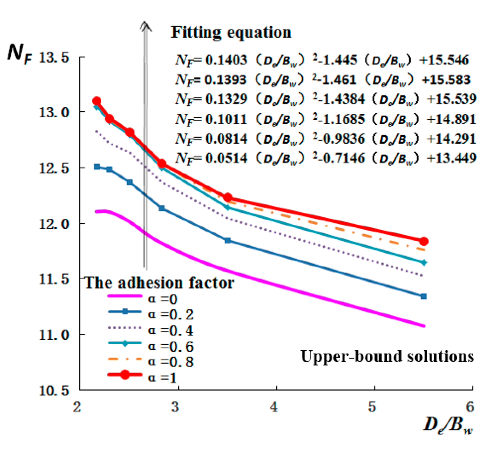
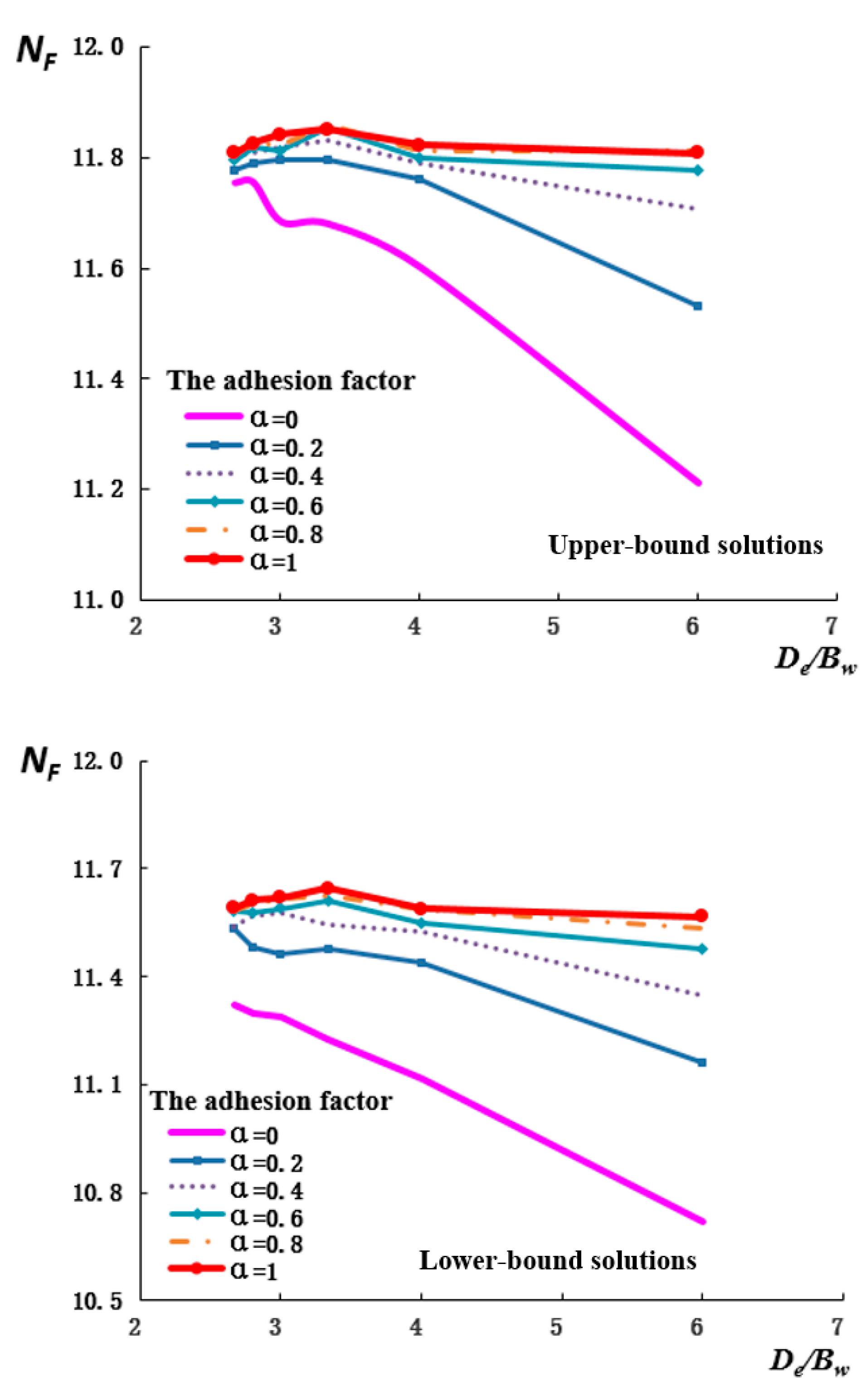
4.1.1. Effect of Wing–Plate Width and Pile–Soil Interaction Coefficient on ULC

Figure 5 show that the upper- and lower-bound solutions for NF for the three-wing pile as De/Bw range from 2.17 to 5.5; it can be observed that NF decreases with an increase in the wing–diameter ratio. The fitting curves are quadratic, and the correlation coefficient is greater than 0.99. When the wing–diameter ratio (De/Bw) is 2.5, that is, the width of the wing plate is 0.2 m, the slope of ULC curve of the three-wing pile becomes slower, so the recommended wing width of the three-wing pile is 0.2 m; the normalized ULC of the three-wing pile rises with the pile–soil interaction coefficient (α) in the different curves. However, when α is greater than 0.4, the curves overlap, and the influence of the pile–soil interaction coefficient on NF is weakened. The parameter De/Bw, although small, significantly influences NF for the three-wing pile (see Figure 5). Keawsawasvong and Ukritchon [27] discovered that, as the side length perpendicular to the direction of the force becomes smaller, the normalized ULC of an I-section pile decreases, mainly because of the increased contact area between the wing plate and soil.
Figure 6 shows that, as De/Bw decreases, the shear plastic ring of the broken soil gradually expands. When De/Bw is 5.5, the maximum distance (L) from the shear plastic ring to the three-wing pile center is 0.38 m, which is 1.9 times the pile diameter (D). The proportion of the soil plastic zone is defined as L/D. When De/Bw was 3.5, 2.8, 2.5, 2.3, or 2.17, L/D was 2.55, 3.15, 3.8, 4.4, or 5.15, respectively. Fitting this data to a quadratic equation relates the proportion of soil plastic zone to the wing–diameter ratio as
L D = 0.5141 ( D e B w ) 2 4.81 D e B w + 12.834
the correlation coefficient R is 0.96.
The shear plastic ring range of the soil around the three-wing pile is positively related to the normalized ultimate bearing capacity. As the width of the wing plate increases, the shear plastic zone of the soil changes from a single ring to multiple rings (see Figure 6). This shows that increasing the width of the wing plate will increase damage to the soil around the pile.
Figure 7 show that NF increases as α varies from 0 to 1. The fitting curves are quadratic, and the correlation coefficient is greater than 0.99. However, when α is greater than 0.6, the increase in NF is not marked; this is consistent with the change trend in Figure 8, which represents the range of the shear plastic zone ring of the soil. When a is greater than 0.4, the maximum distance from the plastic ring to the pile center no longer increases but remains at 0.88 m, which is more than four times the pile diameter. This is a result of the process required to ensure all the soil in the plastic ring reaches the maximum strength. Zhou et al. [11] determined that when the pile–soil interaction coefficient increases, a square plastic zone of the soil appears around an XCC pile. Keawsawasvong and Ukritchon [4] investigated ULC of H piles and determined that the area of the soil failure shear zone increases with the pile–soil interaction coefficient. The soil shear zone changes from an ellipse to a circle, and the plastic zone inside the ellipse decreases. In addition, the pile–soil interaction coefficient affects the distribution of the plastic rings on both sides of the three-wing pile (see Figure 8), which may be affected by the form of the pile section. Because the cross-section of the pile is different, the range of the load transfer from the pile to the soil is different as well.

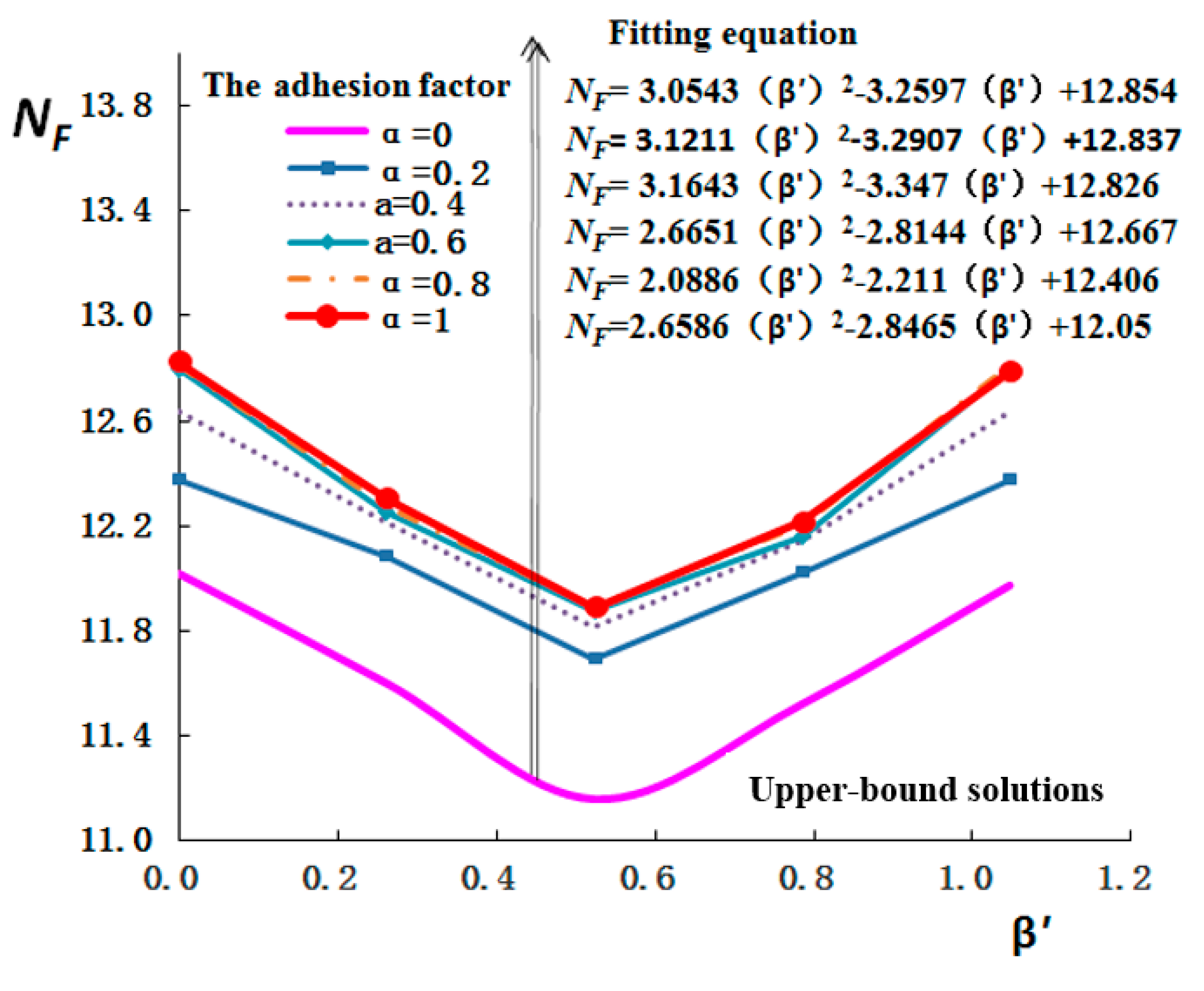
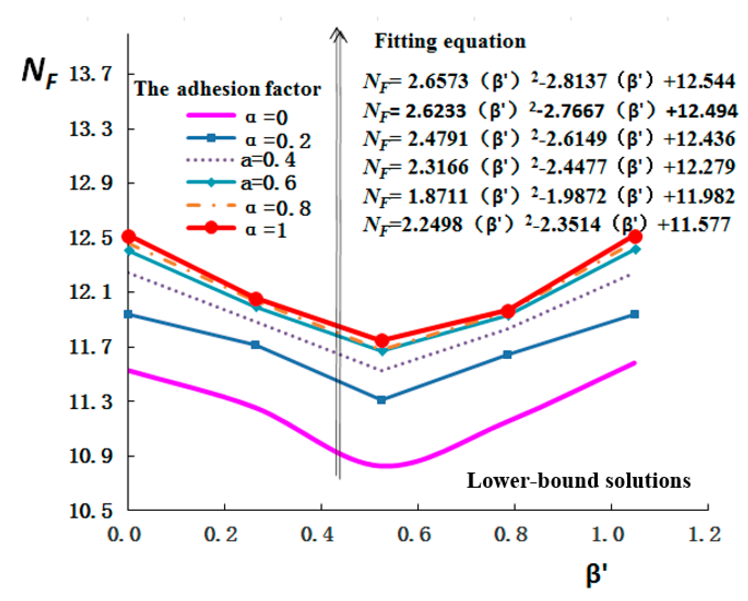
4.1.2. Effect of Lateral-Load Direction on ULC

Figure 9 show that NF of the three-wing pile first decreased and then increased with β’, following a quadratic relationship, for all α in the range 0 to 1. However, the calculation results from the lower-bound solutions of XCC piles show that, when the interaction coefficient is greater than 0.4, the bearing capacity is reduced [11]. This difference is mainly because the ULC of the three-wing pile is restricted by the pile–soil interaction coefficient when the load direction changes.
Figure 10 shows that, as the direction of the lateral load changes from 0 to 60°, the maximum distance from the shear plastic ring to the pile center first increases and then decreases. When β is 0° or 60°, the shear plastic ring of the soil appears as a double ring around the three-wing pile. When β is 30°, the shear plastic ring of the soil appears as a single ring; the distance from the plastic ring to the pile center is the largest, and the ULC is the smallest. Therefore, the size of the shear plastic ring has less influence on the ULC of the three-wing pile than the number of plastic rings. Ukritchon and Keawsawasvong [28] determined that, when the load direction of the rectangular pile changes, the extent of the plastic zone expands towards the direction of the lateral load. However, there is a larger change in the direction of the farthest point of the shear plastic ring to the center of the three-wing pile as the load direction changes (Figure 10). This shows that the shear plastic area of the soil around the three-wing pile changes with the load direction. Therefore, the soil reinforcement should be from the pile center to the maximum radius of the shear plastic ring around the pile.

4.2. Four-Wing Pile

4.2.1. Effect of Wing-Plate Width and Pile–Soil Interaction Coefficient on ULC

Figure 11 show the upper- and lower-bound solutions for NF for the four-wing pile as De/Bw ranges from 2.67 to 6. NF increases with α for the different curves. When α is greater than 0.4, NF first increases and then decreases with an increase in the De/Bw; the maximum occurs when De/Bw is 3.3 (see Figure 11), so the recommended width of the four-wing pile is 0.15 m. This is different from the three-wing–pile case (see Figure 5), mainly because ULC and equivalent diameter are changing during the calculation of NF. When the wing width is equal to 0.15 m and the pile–soil interaction coefficient is equal to 0.4, the ULC of the four-wing pile is 295.79 kN, whereas that of the three-wing pile is 262.94 kN: the ULC increased by 19.9% (see Figure 5 and Figure 11). It is recommended to use the four-wing pile if the engineering cost is sufficient in the foundations of Dapeng Bay. Murphy [29] indicated that the ULC of two-wing piles increased by 16% and 36% for two different wing lengths, compared with that of a round pile of the same diameter. This shows that both width of wing panels and their lengths affect the ULC of the wing pile.
Figure 12 shows that, as Bw of the four-wing pile decreases, the shear plastic ring of the soil gradually expands. When Bw is greater than 0.2 m, the shear plastic ring of the soil around the four-wing pile is less than that of the three-wing pile (see Figure 6 and Figure 12). However, the maximum distance of the plastic ring to the four-wing–pile center is 1 m, whereas the maximum distance of the plastic ring to the three-wing–pile center is 1.03 m. The difference is small, which shows that increasing the number of wing plates has little effect on the range of the soil shear plastic ring. As in the calculation for the three-wing pile, L/D was fitted to a quadratic in De/Bw:
L D = 0.5061 ( D e B w ) 2 5.22 D e B w + 15.07
The correlation coefficient R was 0.96.
Figure 13 show the upper- and lower-bound solutions for NF for the four-wing pile increase as α varied from 0 to 1. The change trend was similar to that of the three-wing pile (see Figure 7). However, when α was greater than 0.2, the increase in NF was not prominent, which is consistent with the range of the plastic ring that belongs to the broken soil in Figure 14. Comparing three- and four-wing piles, the pile–soil interaction coefficient has relatively little effect on the maximum distance from the plastic ring to the pile center (see Figure 14).

4.2.2. Effect of Lateral-Load Direction on ULC

Figure 15 show that the upper- and lower-bound solutions for NF decrease quadratically as β goes from 0 to 45°. When α is 0.4, according to the upper-bound solutions, the maximum NF of the four-wing pile is 11.8179 and the minimum NF is 10.866, a decrease of 9.9%. Under the same conditions, the maximum NF of the three-wing pile in different directions is 6.5% lower than its minimum value (see Figure 9). This shows that the normalized ULC of the four-wing piles is more sensitive to direction changes than that of three-wing piles. Babu and Viswanadham [7] considered the difference in ULC of the four-wing pile was 5% in dense sand, as the direction of the lateral load varied between 0 and 45° because the influence of direction on wing–pile ULC depends on the type of soil.
Figure 16 shows that, when β is between 0° and 45°, the maximum distance from the shear plastic ring of soil to the pile center increases and the shear plastic ring of the soil appears as a double ring around the four-wing pile. However, the shear plastic ring of the soil mainly appears as a single ring around the three-wing piles when β is between 15° and 45° (see Figure 10). Pile-failure tests have revealed that cracks around three-wing piles are less than those of four-wing piles. This shows that four-wing piles have a more symmetrical influence on the surrounding soil than three-wing piles, and that higher reinforcement is needed for soil around the four-wing pile than around a three-wing pile.
The ULC of piles in undrained clay is also affected by factors such as the pile length, pile diameter, and soil gravity density [30,31,32,33]. The position of the wing plate along the pile body also affects the plastic zone of the soil on the side of the pile [7]. These issues need further investigation via three-dimensional limit analysis. The current research should be applicable to clay, silt, and silty clay strata deposited in still water environments such as bays, and further research is needed for coarse-grained strata deposited in dynamic water environments.

5. Conclusions

The ULCs of three- and four-wing piles with different wing widths, pile–soil interaction coefficients, and load directions were investigated in saturated silty clay. The shear plastic zone of the soil around the pile was studied to find conditions where the multi-wing pile reached its ultimate lateral capacity. Based on the upper- and lower-limit solutions, the following conclusions can be drawn:
(1)
When the empirical equation of ULC of the three-wing piles that varied with each parameter was fitted (with a correlation coefficient greater than 0.99), the width of the wing plate was found to have a significant influence on ULC of the wing pile.
(2)
The normalized ULC of the three-wing pile increased with the pile–soil interaction coefficient. The change trend was similar in the four-wing pile; however, when the pile–soil interaction coefficient was greater than 0.2, the increase in the normalized ULC of the four-wing pile was not prominent.
(3)
For both three-wing and four-wing piles, the pile–soil interaction coefficient had relatively little effect on the maximum distance from the shear plastic ring of the soil to the pile center.
(4)
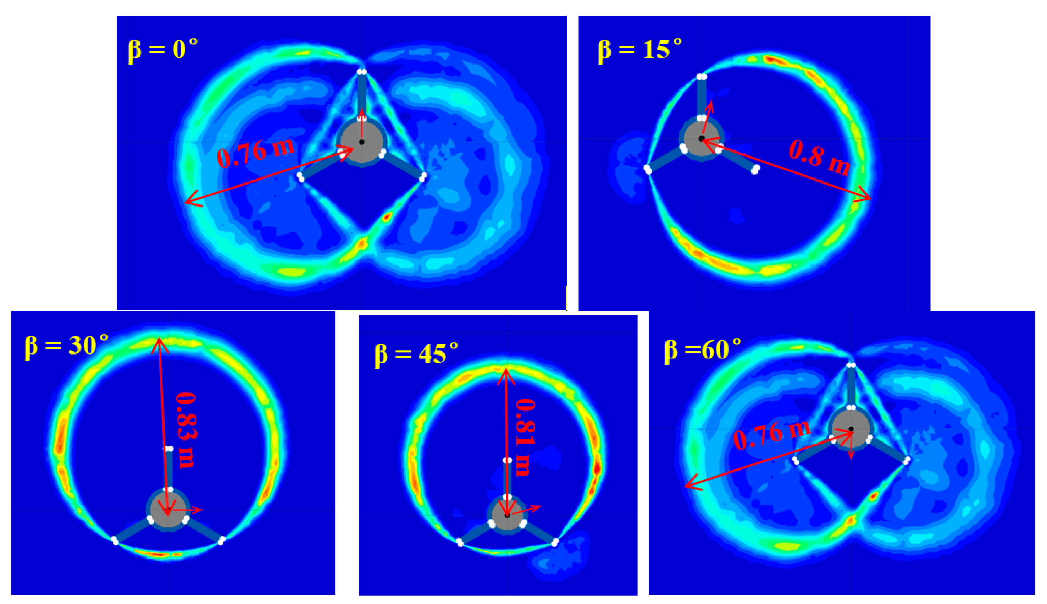
When the wing width was 0.3, the maximum distance from the shear plastic ring of the soil to the three-wing pile center was 1.03 m, which is more than five times the pile diameter. However, under the same conditions, the four-wing pile did not show any increase in the shear plastic zone of the soil around the pile.
(5)
There was a double shear plastic ring of soil around the four-wing pile. The four-wing piles had a more symmetrical influence on the soil around the piles than the three-wing ones. When both the three-wing pile and the four-wing pile reach their respective ultimate bearing capacities, the reinforcement needed for the soil around a four-wing pile will therefore be higher than for that around a three-wing pile.

Author Contributions

Conceptualization: H.W., D.F., T.Y., L.M., W.L. and D.P.; Methodology: D.F. and D.P.; Software: H.W.; Validation: L.M., W.L. and H.W.; Formal analysis: T.Y. and L.M.; Investigation: H.W.; Resources: H.W.; Data curation: T.Y.; Writing—Original draft preparation: H.W.; Writing—Review and editing: H.W., D.F., T.Y., L.M., W.L. and D.P.; Visualization: T.Y.; Supervision: H.W.; Project administration: L.M.; Funding acquisition: W.L. All authors have read and agreed to the published version of the manuscript.

Funding

This research was funded jointly by the China Postdoctoral Science Foundation (Grant No. 2020M672202), the Youth project of Henan Natural Science Foundation (Grant No. 212300410125), Key projects of universities in Henan Province (Grant No. 20A570002), and the Engineering Research Center for Embankment Safety and Disease Control of Ministry of Water Resources (No. LSDP202202).

Institutional Review Board Statement

Not applicable.

Informed Consent Statement

Not applicable.

Data Availability Statement

Not applicable.

Acknowledgments

The authors would like to thank Starfin Australia for leading the Winged Pile Study.

Conflicts of Interest

The authors declare no conflict of interest.

References

  1. Zhou, H.; Yuan, J.; Liu, H. A general analytical solution for lateral soil response of non-circular cross-sectional pile segment. Appl. Math. Modell. 2019, 71, 601–631. [Google Scholar] [CrossRef]
  2. Deb, T.K.; Singh, B. Response and capacity of monopod caisson foundation under eccentric lateral loads. Mar. Georesour. Geotechnol. 2018, 36, 452–464. [Google Scholar] [CrossRef]
  3. Zhu, B.; Ren, J.; Ye, G.L. Wave-induced liquefaction of the seabed around a single pile considering pile–soil interaction. Mar. Georesour. Geotechnol. 2018, 36, 150–162. [Google Scholar] [CrossRef]
  4. Keawsawasvong, S.; Ukritchon, B. Undrained lateral capacity of I-shaped concrete piles. Songklanakarin J. Sci. Technol. 2017, 39, 751–758. [Google Scholar] [CrossRef]
  5. Broms, B.B. Lateral resistance of piles in cohesive soils. J. Soil Mech. Found. Div. 1964, 90, 27–63. [Google Scholar] [CrossRef]
  6. Nasr, A.M.A. Experimental and theoretical studies of laterally loaded finned piles in sand. Can. Geotech. J. 2014, 51, 381–393. [Google Scholar] [CrossRef]
  7. Babu, K.V.; Viswanadham, B.V.S. Numerical studies on lateral load response of fin piles. Geomech. Geoengin. 2018, 14, 85–98. [Google Scholar] [CrossRef]
  8. Sakr, M.A.; Azzam, W.R.; Wahba, M.A. Model study on the performance of single-finned piles in clay under lateral load. Arab. J. Geosci. 2020, 13, 1–16. [Google Scholar] [CrossRef]
  9. Dührkop, J.; Grabe, J. Laterally loaded piles with bulge. J. Offshore Mech. Arct. Eng. 2008, 130. [Google Scholar] [CrossRef]
  10. Zhou, H.; Liu, H.L.; Ding, X.; Kong, G. A p–y curve model for laterally loaded XCC pile in soft clay. Acta Geotech. 2020, 15, 3229–3242. [Google Scholar] [CrossRef]
  11. Zhou, H.; Liu, H.; Wang, L.; Kong, G. Finite element limit analysis of ultimate lateral pressure of XCC pile in undrained clay. Comput. Geotech. 2018, 95, 240–246. [Google Scholar] [CrossRef]
  12. Yaghobi, M.H.; Hanaei, F.; Fazel Mojtahedi, S.F.F.; Rezaee, M. Numerical finite element analysis of laterally loaded fin pile in sandy soil. Innov. Infrastruct. Solut. 2019, 14. [Google Scholar] [CrossRef]
  13. Peng, J.-R.; Rouainia, M.; Clarke, B.G. Finite element analysis of laterally loaded fin piles. Comput. Struct. 2010, 88, 1239–1247. [Google Scholar] [CrossRef]
  14. Bienen, B.; Dührkop, J.; Grabe, J.; Randolph, M.F.; White, D.J. Response of piles with wings to monotonic and cyclic lateral loading in sand. J. Geotech. Geoenviron. Eng. 2012, 138, 364–375. [Google Scholar] [CrossRef]
  15. Adeel, M.B.; Jan, M.A.; Aaqib, M.; Park, D. Development of simulation basedp-multipliers for laterally loaded pile groups in granular soil using 3D nonlinear Finite Element Model. Appl. Sci. 2021, 11, 26. [Google Scholar] [CrossRef]
  16. Adeel, M.B.; Aaqib, M.; Pervaiz, U.; Rehman, J.U.; Park, D. Numerical response of pile foundations in granular soils subjected to lateral load. Geomech. Eng. 2022, 28, 11–23. [Google Scholar] [CrossRef]
  17. Randolph, M.F.; Houlsby, G.T. The limiting pressure on a circular pile loaded laterally in cohesive soil. Géotechnique 1984, 34, 613–623. [Google Scholar] [CrossRef]
  18. Martin, C.M.; Randolph, M.F. Upper-bound analysis of lateral pile capacity in cohesive soil. Géotechnique 2006, 56, 141–145. [Google Scholar] [CrossRef]
  19. Martin, C.M.; White, D.J. Limit analysis of the undrained bearing capacity of offshore pipelines. Geogr. Tech. 2012, 62, 847–863. [Google Scholar] [CrossRef]
  20. Truong, P.; Lehane, B.M. Effects of pile shape and pile end condition on the lateral response of displacement piles in soft clay. Géotechnique 2018, 68, 794–804. [Google Scholar] [CrossRef]
  21. Albusoda, B.S.; Al-Saadi, A.F.; Jasim, A.F. An experimental study and numerical modeling of laterally loaded regular and finned pile foundations in sandy soils. Comput. Geotech. 2018, 102, 102–110. [Google Scholar] [CrossRef]
  22. Taghavi, A.; Muraleetharan, K.K. Analysis of laterally loaded pile groups in improved soft clay. Int. J. Geomech. 2017, 17, 04016098. [Google Scholar] [CrossRef]
  23. Zhou, H.; Liu, H.; Li, Y.Z.; Ding, X. Limit lateral resistance of XCC pile group in undrained soil. Acta Geotech. 2020, 15, 1673–1683. [Google Scholar] [CrossRef]
  24. Zhao, Z.; Kouretzis, G.; Sloan, S.; Gao, Y. Ultimate lateral resistance of tripod pile foundation in clay. Comput. Geotech. 2017, 92, 220–228. [Google Scholar] [CrossRef]
  25. Butterfield, R. Dimensional analysis for geotechnical engineering. Géotechnique 2009, 49, 357–366. [Google Scholar] [CrossRef]
  26. Fatahi, B.; Basack, S.; Ryan, P.; Zhou, W.H.; Khabbaz, H. Performance of laterally loaded piles considering soil and interface parameters. Geomech. Eng. 2014, 7, 495–524. [Google Scholar] [CrossRef]
  27. Keawsawasvong, S.; Ukritchon, B. Ultimate lateral capacity of two dimensional plane strain rectangular pile in clay. Geomech. Eng. 2016, 11, 235–252. [Google Scholar] [CrossRef]
  28. Ukritchon, B.; Keawsawasvong, S. Undrained lateral capacity of rectangular piles under a general loading direction and full flow mechanism. KSCE J. Civ. Eng. 2018, 22, 2256–2265. [Google Scholar] [CrossRef]
  29. Murphy, G.; Doherty, P.; Cadogan, D.; Gavin, K.G. Field experiments on instrumented winged monopiles. Proc. Inst. Civ. Eng. Geotech. Eng. 2016, 169, 227–239. [Google Scholar] [CrossRef]
  30. Bisaws, S.K.; Mukherjee, S.; Chakrabarti, S.; De, M. Experimental investigation of free head model piles under lateral load in homogenous and layered sand. Int. J. Geotech. Eng. 2015, 9, 363–378. [Google Scholar] [CrossRef]
  31. Pan, J.L.; Goh, A.T.C.; Wong, K.S.; Teh, C.I. Model tests on single piles in soft clay. Can. Geotech. J. 2000, 37, 890–897. [Google Scholar] [CrossRef]
  32. Zhou, H.; Yuan, J.; Liu, H.; Kong, G. Analytical model for evaluating XCC pile shaft capacity in soft soil by incorporating penetration effects. Soils Found. 2018, 58, 1093–1112. [Google Scholar] [CrossRef]
  33. Martin, C.M. The use of adaptive finite element limit analysis to reveal slip-line fields. Geotech. Lett. 2011, 1, 23–29. [Google Scholar] [CrossRef]
Figure 1. Flowchart for the research processes.
Jmse 10 01391 g001
Figure 2. Calculated section of three-wing pile.
Jmse 10 01391 g002
Figure 3. Calculated section of four-wing pile.
Jmse 10 01391 g003
Figure 4. Calculation results for circular-pile model. (a) circular-pile-model self-adaptive computing grid; (b) a comparison of results calculated by Randolph and Houlsby (1984) with those using the method from this study. (α: pile–soil interaction coefficient; NF: normalized ultimate lateral capacity).
Jmse 10 01391 g004
Figure 5. Relationship between the normalized ultimate lateral capacity (NF) of the three-wing pile and the wing–diameter ratio (De/Bw) when lateral-load angle β = 0. (Top) Upper-bound and (Bottom) lower-bound solutions from limit analysis with different pile-soil interaction coefficients (adhesion factors).
Jmse 10 01391 g005aJmse 10 01391 g005b
Figure 6. Influence of various wing–diameter ratios of the three-wing pile on the shear plastic zone of the soil when load angle β = 0 and pile–soil interaction coefficient a = 0.4. (De: effective diameter; Bw: wing width.).
Jmse 10 01391 g006
Figure 7. Relationship between the normalized ultimate lateral capacity (NF) of the three-wing pile and the pile–soil interaction coefficient (α) when lateral-load angle β = 0. (Top) Upper-bound and (Bottom) lower-bound solutions from limit analysis with different wing-to-diameter ratios. (De: effective diameter; Bw: wing width.).
Jmse 10 01391 g007
Figure 8. Influence of the different pile–soil interaction coefficients a on the shear plastic zone of the soil around the three-wing pile when lateral-load angle β = 0 and wing–diameter ratio is 2.3.
Jmse 10 01391 g008
Figure 9. Relationship between the normalized ultimate lateral capacity (NF) of the three-wing pile and the direction of the lateral load (β’) when the wing-to-diameter ratio De/Bw = 2.5. (Top) upper-bound and (Bottom) lower-bound solutions from limit analysis with different pile–soil interaction coefficients (adhesion factors).
Jmse 10 01391 g009aJmse 10 01391 g009b
Figure 10. Effect of different lateral-load directions on the shear plastic zone of the soil around the three-wing pile when pile–soil interaction coefficient a = 0.4 and De/Bw = 2.5. (De: effective diameter; Bw: wing width.).
Jmse 10 01391 g010
Figure 11. Relationship between the normalized ultimate lateral capacity (NF) of the four-wing pile and the wing–diameter ratio (De/Bw) when lateral-load angle β = 0. (Top) Upper-bound and (Bottom) lower-bound solutions from limit analysis with different pile–soil interaction coefficients (adhesion factors).
Jmse 10 01391 g011
Figure 12. Influence of various wing widths Bw on the shear plastic zone of the soil around the four-wing pile when lateral-load angle β = 0 and pile–soil interaction coefficient a = 0.4.
Jmse 10 01391 g012
Figure 13. Relationship between the normalized ultimate lateral capacity (NF) of the four-wing pile and the pile–soil interaction coefficient (α) when lateral-load angle β = 0. (Top) Upper-bound and (Bottom) lower-bound solutions from limit analysis with different wing-to-diameter ratios. (De: effective diameter; Bw: wing width.).
Jmse 10 01391 g013aJmse 10 01391 g013b
Figure 14. Influence of the different pile–soil interaction coefficients a on the shear plastic zone of the soil around the four-wing pile when lateral-load angle β = 0 and wing–diameter ratio De/Bw = 3.3.
Jmse 10 01391 g014
Figure 15. Relationship between the normalized ultimate lateral capacity (NF) of the four-wing pile and the direction of the lateral load (β’) when the wing-to-diameter ratio De/Bw = 3. (Top) upper-bound and (Bottom) lower-bound solutions from limit analysis with different pile–soil interaction coefficients (adhesion factors).
Jmse 10 01391 g015
Figure 16. Effect of the different lateral-load directions on the shear plastic zone of the soil around the four-wing pile when pile–soil interaction coefficient a = 0.4 and wing–diameter ratio De/Bw = 3.
Jmse 10 01391 g016
Table 1. Physical and mechanical properties of Dapeng Bay soil.
Soil ClassificationAverage Soil Depth h (m)Saturated Density rsat (g/cm3)Compression Modulus Es (Mpa)Shear Strength Su (kPa)Liquid Index IpFoundation-Bearing Capacity fa (kPa)
Silty clay2.5230504.4140
Sand and clay interlayer52.1360-6200
Publisher’s Note: MDPI stays neutral with regard to jurisdictional claims in published maps and institutional affiliations.

